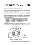
1
Spicer® Drive Axle Service Manual Spicer® Drive Axle AXSM-0400 September 2007 This bulletin contains product improvement information. Dana Corporation is not commited or liable for canvassing existing product. Spicer Axle Service and Maintenance Instructions The Spicer 4x4 Drive System Dana Corporation presents this publication to aid in maintenance and overhaul of Spicer 4x4 Drive systems. Axle models and other equipment covered in this publication are listed below. Spicer Rear Drive Axles for 4x4 Drive Systems Contents Section No. 4x4 Drive System • Description . . . . . . . . . . . . . . . . . . . . . . . . . . . . . . . . . . . . . . . . . . . page ii • Operation . . . . . . . . . . . . . . . . . . . . . . . . . . . . . . . . . . . . . . . . . . . . page iii Steer-Drive Axle . . . . . . . . . . . . . . . . . . . . . . . . . . . . . . . . . . . . . . . . . 1 • Differential Carrier . . . . . . . . . . . . . . . . . . . . . . . . . . . . . . . . . . . . . 2 Rear Axle . . . . . . . . . . . . . . . . . . . . . . . . . . . . . . . . . . . . . . . . . . . . . . . 3 • Power Divider . . . . . . . . . . . . . . . . . . . . . . . . . . . . . . . . . . . . . . . . . 4 • Differential Carriers (Single Reduction) . . . . . . . . . . . . . . . . . . . . . 5 • Differential Carriers (Dual Range and Double Reduction) . . . . . . . 6 Controlled Traction Differential . . . . . . . . . . . . . . . . . . . . . . . . . . . . . . 7 Shift Systems . . . . . . . . . . . . . . . . . . . . . . . . . . . . . . . . . . . . . . . . . . . 8 Fastener Tightening Specifications . . . . . . . . . . . . . . . . . . . . . . . . . . 9 Spicer 4x4 Drive System Spicer combines a unique power divider with a Spicer conventional axle to provide a 4x4 rear drive axle. This drive axle coupled by a driveline to a steer-drive axle are the basic components of the Spicer 4x4 Drive System. Gearing Combinations The Spicer 4x4 Drive System is available in the following gearing combinations: Shift Systems The vehicle drive uses cab-mounted air control valves to control the drive system operating modes, axle range selections and controlled traction differential operation. Detailed descriptions of air shift systems which control these functions are contained in the Shift System Section of this manual. Operation The power divider transfer gearing provides the means to deliver power to the steer-drive axle. Operating modes and power flow are illustrated below. The transfer gearing includes a mechanical sliding clutch which, in turn, controls engagement and disengagement of the driveline to the steer-drive axle. 4x4 Operating Mode In 4x4 mode, the sliding clutch is engaged and drive is direct from transmission to the helical gear train in the power divider. At this point, power is distributed through the three helical gears to the rear axle and to the steer-drive axle. 4x2 Operating Mode For 4x2 operating mode, the sliding clutch is disengaged and power flow is direct from transmission, through two helical gears with 100% to rear axle. Spicer Axles & Brakes Contents Section 1, Page No. ESD-18 STEER-DRIVE AXLE Introduction . . . . . . . . . . . . . . . . . . . . . . . . . . . . . . . . . . . . . . . . . . . . . 2 STEERING AND WHEEL END EQUIPMENT Wheel Alignment and Wheel End Inspection . . . . . . . . . . . . . . . . . . . . 3 Lubrication . . . . . . . . . . . . . . . . . . . . . . . . . . . . . . . . . . . . . . . . . . . . . . 6 Overhaul . . . . . . . . . . . . . . . . . . . . . . . . . . . . . . . . . . . . . . . . . . . . . . . . 7 Section 2, Page No. DIFFERENTIAL CARRIER Contents . . . . . . . . . . . . . . . . . . . . . . . . . . . . . . . . . . . . . . . . . . . . . . . 1 Lubrication . . . . . . . . . . . . . . . . . . . . . . . . . . . . . . . . . . . . . . . . . . . . . 2 Cleaning, Inspection and Replacement . . . . . . . . . . . . . . . . . . . . . . . 4 Adjustments . . . . . . . . . . . . . . . . . . . . . . . . . . . . . . . . . . . . . . . . . . . . 6 Differential Carrier Replacement . . . . . . . . . . . . . . . . . . . . . . . . . . . . 10 DIFFERENTIAL CARRIER OVERHAUL Single Reduction . . . . . . . . . . . . . . . . . . . . . . . . . . . . . . . . . . . . . . . . 13 Dual Range and Double Reduction . . . . . . . . . . . . . . . . . . . . . . . . . 22 ESD-18 Steer-Drive Axle Introduction This manual includes instructions for the Spicer ESD-18 Steer-Drive Axle (capacity rating 18,000 lbs.). This axle may include one of three types of gearing: single reduction, dual range or double reduction. The single reduction gearing may be equipped with a Spicer Controlled Traction Differential. For service information on this special differential, refer to separate section in this manual. The axle housing is one piece. A special ball and socket assembly and wheel end equipment are provided at each end of the housing. The axle shaft assembly on each side of the axle is equipped with cardan-type universal joint. These joints are housed in a trunnion-type ball and socket assembly to provide steering capabilities. The axle is equipped with Spicer Single-Anchor Pin Air Brakes (16-1/2” x 5”). Wheel Alignment and Wheel End Inspection Front Wheel Bearings 1. When the front wheel bearings are excessively worn or damaged, check the bearing cups for proper installation before removing them for replacement. If a cup is improperly seated in the hub, inspect the hub for burrs, rough spots, or other irregular surfaces that would prevent seating the cup properly. 2. Bearing damage is often caused by lack of lubrication or improper adjustment. When installing bearing cups or cones and rollers, make sure that the specified lubricant is properly used. Adjust the bearings after installation. General Inspection Proper wheel alignment promotes longer tire wear, ease of handling, and minimizes strain on front suspension and axle components. Do not check and adjust front wheel alignment without first making the following inspection for front end maladjustments, damage or wear. Wheels 1. Check the air pressure in all the tires. Make sure that the pressures agree with those specified for the tires and vehicle model being checked 1. 2. Raise the front of the vehicle off the floor. Grasp each front tire at the front and rear, and push the wheel inward and outward. If any free play is noticed between the brake drum and the brake backing plate, adjust the wheel bearings. Replace the bearings if they are worn or damaged. Adjust and/or replace worn or damaged bearings. Wheel stud nuts should be inspected and tightened twice in the first 500 miles, and again after 1,000 miles to avoid accidental loosening of the wheels. Loose wheel stud nuts may cause shimmy and vibration. Elongated stud holes in the wheels may also result from loose stud nuts. 2. Keep the wheels and hubs clean. Stones or lumps of mud wedged between the wheel and drum will unbalance a wheel and tire. 3. Check for damage that would affect the runout of the wheels. Wobble or shimmy caused by a damaged wheel will eventually damage the wheel bearings. Inspect the wheel rims for dents that could permit air to leak from the tires. 3. Check brakes for dragging and wheels for proper balance. 4. Check all steering linkage for wear or maladjustment. Adjust and/ or replace worn parts. 5. Check the steering gear mounting bolts, and torque them wherever required. Check the front spring clips (U-bolts) and the spring tie bolt, and tighten them if necessary. 6. Spin each front wheel with a wheel spinner, and check and balance each wheel as required. 7. Rotate each front wheel slowly, and observe the amount of lateral or side runout. If the wheel runout exceeds 1/8 inch, replace the wheel or install the wheel on the rear. Kingpin Tires 1. The tires should be checked frequently to be sure that the air pressures agree with those specified for the tires and vehicle model. 2. Inspect the tire treads, and remove all stones, nails, glass, or other objects that may be wedged in the tread. Check for holes or cuts that may permit air leakage from the tire, and make the necessary repairs. 3. Inspect the tire side walls for cuts, bruises, and other damage. If internal damage is suspected, demount the tire from the wheel for further inspection and repair or replacement. 4. Check the tire valve for air leaks, and replace the valve if necessary. Replace any missing valve caps. Check kingpin bearing nut tightness after first 1000 miles; yearly after that. Wheel Alignment and Wheel End Inspection Lubrication Steering and Wheel End Equipment Steer-Drive Axle Steering and Wheel End Equipment Steering and Wheel End Equipment Overhaul Steering and Wheel End Equipment Overhaul Brakes (Left-hand Illustrated) Steering and Wheel End Equipment Overhaul Steering and Wheel End Equipment Overhaul Steering and Wheel End Equipment Overhaul Steering and Wheel End Equipment Overhaul Steering and Wheel End Equipment Overhaul Steering and Wheel End Equipment Overhaul Steering and Wheel End Equipment Overhaul Steering and Wheel End Equipment Overhaul Differential Carriers for ESD-18 Steer-Drive Axles These instructions cover service and maintenance for the steer-drive axle differential carrier. For information on single reduction gearing with Spicer Controlled Traction Differential, refer to Section 7. Multigrade gear lubricants which meet the requirements of military specification MIL-L-2105-C are recommended for use in Spicer drive axles. These lubricants per form well over broad temperature ranges, providing good gear and bearing protection in a variety of climates. The MIL-L-2105-C specifi cation divides lubricants into three major categories on the basis of lube viscosity at various tempera tures. These are 75W, 80W-90 and 85W-140. 80W-140 lubricants are also available, but are listed with 80W-90 by MIL-L-2105-C. Lubricants approved under MIL-L-2105-B are also acceptable for use in Spicer Axles. Synthetic Lubricants: Use of synthetic lubricants in Spicer Axles is approved only after Engineering Department review. This is essen tial to ensure proper seal life and axle performance with a particular synthetic. For additional informa tion, contact Spicer Field Service Department, or call Regional Office. See back cover for address and phone numbers. Oil Additives: The use of oil additives is not approved for use in Spicer axles. Contact Spicer Field Service Department, or call Regional Office for specific recommendations. See back cover for address and phone numbers. Cleaning, Inspection, Replacement Silicone Rubber Gasket Compound — For more effective sealing, Spicer uses silicone rubber gasket compound to seal the majority of metal-tometal mating surfaces. Spicer includes gasket compound and application instructions in many repair parts kits. It is recommended that this compound be used in place of conventional gaskets. The compound will provide a more effective seal against lube seepage and is easier to remove from mating surfaces when replacing parts. Always use Spicer Genuine Axle Parts and Parts Kits. Genuine Spicer replacement parts are the same high quality tolerances as the original axle components and include the latest engineering improvements. Parts Kits have only one part number which makes ordering, stocking and servicing easier. They are not only convenient, but give the advantage of having every part needed for a good repair job. Adjustments Adjustments Adjustments Differential Carrier Replacement Differential Carrier Assembly Differential Carrier Overhaul Differential Carrier Overhaul (Single Reduction) Differential Carrier Overhaul Differential Carrier Overhaul Differential Carrier Overhaul Differential Carrier Overhaul Differential Carrier Overhaul Differential Carrier Overhaul Differential Carrier Overhaul Differential Carrier Overhaul Differential Carrier Overhaul Differential Carrier Overhaul Service and Maintenance Instructions 4x4 Drive System Rear Axle Multigrade gear lubricants which meet the requirements of military specification MIL-L-2105-C are recommended for use in Spicer drive axles. These lubricants per form well over broad temperature ranges, providing good gear and bearing protection in a variety of climates. The MIL-L-2105-C specifi cation divides lubricants into three major categories on the basis of lube viscosity at various tempera tures. These are 75W, 80W-90 and 85W-140. 80W-140 lubricants are also available, but are listed with 80W-90 by MIL-L-2105-C. Lubricants approved under MIL-L-2105-B are also acceptable for use in Spicer Axles. Synthetic Lubricants: Use of synthetic lubricants in Spicer Axles is approved only after Engineering Department review. This is essen tial to ensure proper seal life and axle performance with a particular synthetic. For additional informa tion, contact Spicer Field Service Department, or call Regional Office. See back cover for address and phone numbers. Oil Additives: The use of oil additives is not approved for use in Spicer axles. Contact Spicer Field Service Department, or call Regional Office for specific recommendations. See back cover for address and phone numbers. Capacities listed are approximate. The amount of lubricant will vary with angleof axle as installed in vehicle chassis. Figures do not apply to housings not designed or manufactured by Spicer. Lubrication Cleaning, Inspection, Replacement Cleaning, Inspection, Replacement Silicone Rubber Gasket Compound — For more effective sealing, Spicer uses silicone rubber gasket compound to seal the majority of metal-tometal mating surfaces. Spicer includes gasket compound and application instructions in many repair parts kits. It is recommended that this compound be used in place of conventional gaskets. The compound will provide a more effective seal against lube seepage and is easier to remove from mating surfaces when replacing parts. Always use Spicer Genuine Axle Parts and Parts Kits. Genuine Spicer replacement parts are the same high quality tolerances as the original axle components and include the latest engineering improvements. Parts Kits have only one part number which makes ordering, stocking and servicing easier. They are not only convenient, but give the advantage of having every part needed for a good repair job. Adjustments Adjustments Adjustments Adjustments Adjustments Differential Carrier Replacement Differential Carrier Replacement Power Divider Overhaul for 4x4 Rear Axles 4x4 Power Divider Transfer Gearing Power Divider Overhaul Power Divider Overhaul Power Divider Overhaul Power Divider Overhaul Differential Carriers for 4x4 Rear Axles These instructions cover single reduction differential carrier assemblies for 4x4 rear axles. It is assumed that the power divider assembly has been removed from the carrier. For service information on single reduction carriers equipped with Spicer Controlled Traction Differential, refer to Section 7. 4x4 Rear Axle Single Reduction 185S4, 220S4, 230S4, 260S4, 300S4, 350S4 Differential Carrier Overhaul Differential Carrier Overhaul Differential Carrier Overhaul Differential Carrier Overhaul Differential Carrier Overhaul Differential Carriers for 4x4 Rear Axles 4x4 Rear Axle Dual Range 185T4, 220T4, 230T4, 260T4, 300T4, 350T4 Double Reduction 185P4, 220P4, 230P4, 260P4, 300P4, 350P4 Differential Carrier Overhaul Differential Carrier Overhaul Differential Carrier Overhaul Differential Carrier Overhaul Differential Carrier Overhaul Differential Carrier Overhaul Differential Carrier Overhaul Service and Maintenance Instructions Controlled Traction Differentials Spicer Axle Service and Maintenance Instructions Controlled Traction Differentials Spicer Corporation presents this publication to aid in maintenance and overhaul of Spicer single reduction axles equipped with a biasing-type, controlled traction differential. In this manual, this unit is termed Controlled Traction Differential (or CTD). Two “design types” are contained in this manual: NOTE: In this manual, instructions for both CTD design types are the same except where specified otherwise. This manual includes specific instructions for single reduction, differential carriers (both single drive and tandem axles) equipped with Controlled Traction Differentials. For service instructions covering other axle parts and adjustments, refer to the appropriate Spicer axle service manuals. Spicer Controlled Traction Differen tials (or CTD) incorporate a friction plate assembly designed to transfer torque from the slipping wheel to the one with traction. Engaged, the Spicer CTD converts to a biasing differential and assists in overcom ing adverse operating conditions. Disengaged, it restores convention al differential action for normal road conditions. CTD Overhaul IMPORTANT: Detailed procedures for each type, capacity or model axle may vary. For specific service instructions on your axle, refer to the appropriate Spicer service manual. The following instructions are applicable to axles equipped with Controlled Traction Differentials. 8. Drive Pinion: For pinion instructions, refer to appropriate Spicer Axle Service Manual covering your specific axle model. Medium-duty CTD Overhaul 10. Disassemble and Reassemble Wheel Differential. Refer to the appropriate Spicer Axle Service Manual covering your specific axle. Medium-duty CTD Overhaul Heavy-duty CTD Overhaul 9. Disassemble and Reassemble Wheel Differential. Refer to the appropriate Spicer Axle Service Manual covering your specific axle. Heavy-duty CTD Overhaul 1. Install Ring Gear with Interfer ence Fit. Place gear support case assembly on bench with clutch pack side down. Position ring gear (gear teeth up) on gear support case and align bolt holes. Tempo rarily, install two ring gear bolts to assure alignment, then tap ring gear alternately on opposite sides with a soft-nosed hammer until gear is fully seated against gear support case flange. Turn assembly over, then place in press (gear teeth down) on hard wood blocks. Position blocks to the outside of the ring gear to allow clearance for installation of two alignment bolts. Install alignment bolts, then pro ceed with reassembly procedures in Step 3. CTD Overhaul NOTE: If the drive pinion was removed, refer to the appropriate Spicer Service Manual covering your specific axle for instructions. NOTE: For detailed instructions on checking and adjusting procedures, refer to the appropriate Spicer Service Manual covering your specific axle. CTD Overhaul Service and Maintenance Instructions 4x4 Drive Shift Systems 4x4 Drive Shift Systems Dual Range Axles with Range Interlock Dual Range Axles with Range Interlock Dual Range Axles with Range Interlock Dual Range Axles with Range Interlock Dual Range Axles with Range Interlock Dual Range Rear Axle with Single Reduction Steer-Drive Axle Dual Range Rear Axle with Single Reduction Steer-Drive Axle Dual Range Rear Axle with Single Reduction Steer-Drive Axle Dual Range Rear Axle with Single Reduction Steer-Drive Axle Shift Sytem Components Shift Sytem Components Shift Sytem Components Shift Sytem Components Shift Sytem Components Service and Maintenance Instructions Faster Tightening Specifications 4x4 Drive Systems These instructions include fastener tightening torque values for the steer-drive and tandem axles for 4x4 Drive Systems. Contents are listed below. Correct tightening torque values are extremely impor tant to assure long Spicer Axle life and dependable performance. Under-tightening of attaching parts is just as harmful as over-tightening. Exact compliance with recommended torque values will assure the best results. The data includes fastener size, grade and torque tight ening values. Axle models are included to pinpoint identification of fasteners for your particular axle. To determine bolt or cap screw grade, check for designation stamped on bolt head (see illustration). Eaton Steer-Drive Axle Eaton Steer-Drive Axle Differential Carriers 4x4 Rear Axle Power Dividers (All Models) 4x4 Rear Axle Differential Carriers 4x4 Rear Axle Differential Carriers Dana Aftermarket Group PO Box 321 Toledo, Ohio 43697-0321 Warehouse Distributors: 1.800.621.8084 OE Dealers: 1.877.777.5360 www.spicerparts.com AXSM-0400 Printed in U.S.A. Copyright Dana Limited, 2012. All rights reserved. Dana Limited.