1
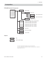
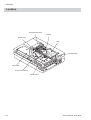
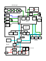
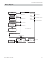
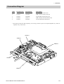
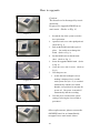
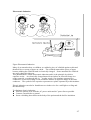
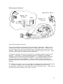
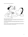
1. GENERAL ECG-9020K Electrocardiograph ECG-9020K RK-0002 Bottom Casing Assy RK-0003 Internal Parts GC-0011 Motor Assy RH-0001 Magazine Assy RK-0004 Thermal Head Assy RK-0005 Speaker Assy RK-0006 Battery Terminal Assy RK-0009 ECG-9020K Top Casing Assy SC-903D Power Unit UT-23561 ECG Control Board UT-2357 Flash ROM Board VL-0001 LCD Assy KD-103E Cart KH-801E Patient Cable Hanger DI-106D Fixing Plate for Cart YC-901D Carrying Case (Optional) • • 1.12 To order a replacement assembly above, use the Code No. To order a replacement component inside an assembly, refer to “Section 7 Replaceable Parts List”. Service Manual ECG-9010/9020 Rev A 1. GENERAL Composition ECG-9620 Standard Components ECG-9620L ECG-9620M ECG-9620N ECG-9620P ECG-9620S ECG-9620T ECG-9620U RHC-0004 Record Assy RHC-00041 RHC-00042 Motor Assy UTC-0009 Paper senser board UTC-0010 Motor sensor board Magazine Assy RKC-0001 RKC-0002 RKC-0003 RKC-0004 RKC-0005 RKC-0006 Transfer Assy (220 V) for L and P version Transfer Assy (230 V) for M version Transfer Assy (240 V) for N version Transfer Assy (110 V) for S version Transfer Assy (120 V) for T version Transfer Assy (127 V) for U version UTC-0006 Key board UTC-0007 ECG control board UTC-0008 Power board Options KD-103E Cart KH-801E Patient Cable Hanger · To order a replacement assembly above, use the Code No. · To order a replacement component inside an assembly, refer to “Section 7 Replaceablet Parts List”. Service Manual ECG-9620 1.17 1. GENERAL Location Thermal Head Assy Motor Assy Speaker Assy LCD Assy (for ECG-9020K only) Flash ROM Board Inverter Board (for ECG-9020K only) ECG Control Board Power Unit Service Manual ECG-9010/9020 Rev A 1.13 1. GENERAL Location Thermal Head Assy Buzzer Motor Assy LCD Transfer Assy Key board ECG control board Power board 1.18 Service Manual ECG-9620 1. GENERAL Block Diagram NOTE The LCD module and inverter board are used for the ECG-9020K only. Piezo-electric buzzer CNA011 CNJ032 (2pin) Flash ROM Board (UT-2357) Motor, Motor sensor, Mark sensor CNA012 CNJ036 (12pin) CNJ011 (80pin) Membrane key CNJ033 (40pin) CNJ021 (80pin) LCD module CNJ012 (12pin) 2 pin 5 pin CNA015 Inverter board Thermal head CNA013 CNJ013 (6pin) CNJ031 (D-SUB 9pin) ECG Control Board (UT-23561) CNJ043 (mini jack) CNJ041 (mini jack) CNJ011 (12pin) SIO EXT-IN CRO CN31 (16pin) AC source CN11 (3pin) Power Unit (SC-903D) CN021 (30pin) CNJ035 (30pin) CNJ091 (D-SUB15pin) Patient Input CN51 (4pin) Battery 1.14 CNA014 Service Manual ECG-9010/9020 Rev A ECG Control board LCD module ECG input connector A/D GA Inverter board Isolater Video RAM 16 KB EXT input Amp/ A/D converter RS232C driver ROM CRO Amp/ A/D converter ECG I/F Port CPU I/F LCD control Sound I/F Buffer RAM 8 KB for thermal head Gate array Flash ROM board 2 MB 32 bit CPU DRAM ROM system software RTC Flash ROM 256KB Data filing Backup batttery Operation panel Power unit 4 bit CPU Font, Local langrage Motor assy Thermal head temperature detection Battery Battery voltage detection Battery charger AC input Flash ROM 1 MB Switching regulator AC/DC selecter DC/DC converter Charge pump Switching regulator +5 V +12 V +24 V to Thermal head Paper senser Paper/paper mark detection Thermal head 5. BOARD/UNIT DESCRIPTION Block Diagram Buzzer CNJ021 (80 pin) CNJ031 (9 pin) CNJ032 (2 pin) SIO connector Motor Motor sensor CNJ043 (miniature plug) CNA011 External input connector CNJ036 (10 pin) Paper sensor Thermal head CNJ041 (miniature plug) CRO output connector CNA012 CNJ011 (16 pin) CNJ101 (34 pin) Key board CNJ201 (12 pin) CNA013 CNJ033 (24 pin) ECG control board LCD Patient cable connector CNJ091 (D-sub 15 pin) CNJ035 (30 pin) CNA014 CNJ201 (30 pin) Battery (SB-901D) Service Manual ECG-9620 Power board CNJ101 (2 pin) Power transformer unit AC socket CNJ102 (3 pin) 5.1 Operation BD SW Paper Sensor 4bits CPU Gate Arry Motor Sensor LCD 320x240 + AC-DC Conv A - MOTOR Contrast Control ECG control BD 16bits CPU PWM Control +12V,-12V 12V +2.5V,-2.5V TRANS A/D Conv Main CPU Gate Arry 2 MB FlashROM Data Files System Setting Lead Fail Detection Pace Marker Detection 16 MB FlashROM Program Font EEPROM 16 Mbits DRAM DC/DC Conv +8V,-8V A/D Conv Ext In Amp CRO AMP RS232C Speaker AMP SPEAKER DC/DC conv 5V DC/DC conv 24V CLOCK RTC TRANS AC INPUT T.H 256 Kbits SRAM 12V Reg 24V Thermal head 12V LCD 256 Kbits SRAM Charge Control Power BD I R L II F R1 R1 R1 C1 C1 C2 C2 C6 C6 I= L-R II = F - R III = II - I aVR = I + II/2 aVL = 2I - II/2 aVF = 2II + I/2 1. GENERAL Connection Diagram Index 1* 2 3 4 5 Connector No. CNA011 CNA012 CNA013 CNA014 CNA015 NK Code No. 543993A 544002A 544029B 544011A 544038A Description ZHR-2 speaker cable (L50) ZHR-12 motor cable (L120, 65) FCN723/DF11(100)/51021(40) EHR-4 battery terminal cable (L150) 51021-0500/51021-0600 (L50) * We cannot provide this cable seperately; we can only provide it as part of a complete Speaker assy. Refer to “Speaker Assy” in Section 8. CNA013 CNA012 CNA015 CNA011 CNA014 Service Manual ECG-9010/9020 Rev A 1.15 6. DISASSEMBLY No. CNA011 CNA012 CNA013 CNA014 Code No. 08SK3.670.00216A 08SK3.670.00181B 08SK3.670.00172A 08SK3.670.00199B Description ZHR-10 L=120, 90, 130 between motor assy and ECG control board PHR-16 L=80, between thermal head and ECG control board PHDR-24VS (W=100), between key board and ECG control board SHDR-30V-S-B (W=60), between power board and ECG control board CNA011 cable CNA012 cable CNA014 cable CNA013 cable Service Manual ECG-9620 6.3 ECG-9620 Power supply +5 V for digital circuit +12 V for analog circuit +24 to 30 V for thermal head +5 V for LCD Motor ECG-9020 Power supply +5 V for digital circuit +12 V for analog circuit +24 V for thermal head +28 V for LCD +12 V for LCD backlight Motor Connector CNJ201 (Power BD) CNJ035 (ECG control BD) CNJ201 (Power BD) CNJ035 (ECG control BD) CNJ201 (Power BD) CNJ035 (ECG control BD) CNJ201 (Key BD) to LCD module CNJ036 (ECG control BD) Motor/Motor sensor/Paper sensor Connector CNJ201 (Power unit) CNJ035 (ECG control BD) CNJ201 (Power unit) CNJ035 (ECG control BD) CNJ301 (Power unit) Thermal head CNJ013 (ECG control BD) LCD module CNJ012 (ECG control BD) Inverter BD CNJ036 (ECG control BD) Motor/Motor sensor/Paper sensor Pin No. pin 12 to 14 (GND: pin 15 to 23) pin 10 to 11 (GND: pin 15 to 23) pin 24 to 30 (GND: pin 15 to 23) pin 7 (GND: pin 2) Motor rotation detection: pin 8 Motor power (+): pin 9 Motor power (-): pin 10 GND: 3 Pin No. pin 25 to 27 (GND: pin 1 to 15) pin 28 and 29 (GND: pin 30) pin 1 to 6 (GND: pin 7 to 24) pin 12 (GND: pin 11) pin 1 (GND: pin 2) Motor rotation detection: pin 10 Motor power (+): pin 11 Motor power (-): pin 12 GND: 8 9. TROUBLESHOOTING AND ERROR MESSAGES Checking the Software Version The software version numbers are also printed at the bottom space of the paper in automatic or manual ECG recording. Model System Software 9.10 ECG analysis Input unit Operator's Manual ECG-9620 9. TROUBLESHOOTING AND ERROR MESSAGES System Information and Error History During power-up and operation the cardiograph continuously checks itself for system failure. If a failure is detected, system information and error history are printed on the recording paper and all operations are stopped. System information and error history are also printed due to transient noise. After printing the system information and error history, the power of the instrument is automatically turned off. NOTE If the same system information appears again after restarting the cardiograph, do not use the cardiograph until service personnel has corrected the cause of the problem. Sending a copy of the system information to your nearest Nihon Kohden distributor helps us to troubleshoot your problem quickly. System Information Indicates an error number to identify the problem. Refer to the Service manual. Error History Indicates the latest three errors and the date of the latest error, as in the example below. Operator's Manual ECG-9620 9.9 3. TROUBLESHOOTING AND SYSTEM ERROR MESSAGE System Error Message During power-up and operation the instrument continuously checks itself for system failure. If a failure is detected, system information and error history are printed on the recording paper and all operations are stopped. System information and error history are also displayed or printed due to transient noise. After printing the system information and error history, the power of the instrument is automatically turned off. NOTE If the same system information appears again after restarting the instrument, do not use the instrument until service personnel has corrected the cause of the problem. Sending a copy of the system information to your nearest Nihon Kohden distributor helps us to troubleshoot your problem quickly. System Information Indicates an error number to identify the problem. To solve the problem, do the corrective action described below. Error No. Meaning 00 Input unit error: An interrupt signal of 2 ms Corrective Action Replace the ECG control board. is generated. 01 Input unit error: There is no response to the Replace the ECG control board. host. 02 Input unit error: Communication protocol Replace the ECG control board. error. 03 4 bit CPU error: Initialization error. Replace the ECG control board. 04 4 bit CPU error: “No response” error. Replace the ECG control board. 05 A key on the key board is short-circuited. Replace the key board. 06 RTC error: No interrupt signal of 125 ms. Replace the ECG control board. 07 RTC error: Incorrect data in SRAM. Replace the ECG control board. 09 The lithium battery to back up the date and Replace the ECG control board. The time and all system settings is completely lithium battery is in the real time clock IC discharged. The system settings other than on the ECG control board. The date and the items described in the following note time is reset to January 1, 1980. are returned to the factory initial settings. 10 Bus error. Replace the ECG control board. 11 Address error. Replace the ECG control board. Service Manual ECG-9620 3.7 3. TROUBLESHOOTING AND SYSTEM ERROR MESSAGE Error No. Meaning Corrective Action 12 Illegal command. Replace the ECG control board. 13 Zero division error. Replace the ECG control board. 14 Power off time out. Replace the ECG control board. 15 EEPROM error: This occurs due to the Replace the ECG control board. EEPROM check error, installed language error or communication error between the host and EEPROM. 16 Local language flash memory error. Replace the ECG control board. 17 ECG model error. Replace the ECG control board. 18 Local language is not installed. Install the local language. 19 Local language is not installed. Install the local language. Error in memory area for local language. Re-install the local language. Local language text file version does not Install the local language text file which is match the ECG software version. the same version as the ECG software. ECG interpretation error (Time over). Check the input waveforms. 20 21 If any noise is superimposed on the waveforms, find and eliminate the cause. If no noise is superimposed on the waveform, replace the ECG control board. 22 The entered information does not match Replace the ECG control board. the data in the flash memory. 27 Program version error. The program is Turn the power off, then on and check that updated. the ECG waveforms are displayed correctly. NOTE • “Error 05” also appears when any key on the operation panel is pressed and held down. • When “Error 08” appears, the following settings are not reset to the factory initial settings even if the instrument is initialized. - display language - hum filter - hospital name - direct/modem connection - recording resolution setting - elapsed time - local language font - saved ECG data 3.8 Service Manual ECG-9620 System Test Calling up the System Test Screen Test Level 1: Power on with pressing and holding the FEED/MARK key [8]. Test Level 2: Power on while pressing and holding the FEED/MARK key [8] and AUTO/MANUAL key [CLR]. The list of the system test items is printed. You can start each system test by entering the number with a key switch. Test No. Page Item T1-00 T1-01 4.7 4.8 Demonstration Recorder T1-05 4.17 Input unit (analog) T1-06 4.18 Calibration Memo ECG analysis is available. Slant lines Characters H and X Grid Paper speed scales (10, 12.5, 25 and 50 mm/s) Lead off detection and patient cable check (Check result is printed) (Check result is printed) T1-04 T1-02 4.15 4.12 LCD/LED Key T1-07 T2-02 4.19 4.25 Communication Thermal head check and adjustment Sensitivity, TC for lead I, II V1 to V6 Digital processing circuit (Check result is printed) For transferring ECG data files ECG-9620: Enter the number according to the resistance (T2-41 to 49) Reference System Setting: Power on while pressing and holding the COPY/CAL key [0]. ― Q&A ― (ECG-9010/9020/9110/9130) 1. The life time of the battery (LCT-1912ANK/12V1.9Ah) • The capacity of the battery will be half by discharging and charging 300 times. Although it depends on frequency in use of the doctor, the life time of the battery is about 1 year. Also replace the battery when it cannot last for 15 minutes during battery operation at the temperature between 20 and 30 degrees. 2. The life time of the thermal head • Replace the thermal head after 30 km recording. For example, if the paper is used 60 cm (6 channel auto recording + analysis + dominant) per one patient, it can be record for about 5000 patients. 3. The life time of the LCD backlight (ECG-9020/9130) • The brightness of the backlight may be half by using 10000 hours. In other word, it may last 6 years by using 6 hours a day and 5 days a week. 4. The life time of the lithium battery. • Replace the lithium battery on the ECG control board when the No. 08 or 09 system error message appears or after the lithium battery is used for 7 years. The life time of the lithium battery is about 7 years. The parts number and the cord number is as follows. NK parts number: BR2032/1F2 NK cord number: 3907653 5. We know that the ECG-9010/9020/9110/9130 does not function stress test. But we want to examine the stress test on the manual mode by using those ECG. Do you have any recommended patient cable to use in the stress test. • As you know already, the ECG-9010/9020/9110/9130 does not function stress test. But we are preparing the patient cable for the disposable electrode. You can specify the lead length of limb and chest. Please see the attached paper. 6. During AC operation without battery, the power was turned off. And the "system error 22" was printed. How do I have to do? • Regarding ECG-9010 and 9020, it occurred because the condenser does not include on the control board. Please confirm the S/N of the ECG. The following S/N is the already measured. There is not problem regarding ECG9110 and ECG-9130. ECG-9010: 00312 or later ECG-9020: 00182 or later However even if the ECG-9010, 9020, 9110 or 9130 is operated AC power, use the battery necessary in order to prevent the trouble. Because battery works as a condenser. If the "error 22" occurs, the ECG must be returned to Nihon Kohden for repair. 1 7. Regarding ECG-9010, 9020, 9110 and 9130, the analysis age is more than 3 years old. Cannot you analyze under the age of 3? • We Nihon Kohden analyze the ECG data by getting the ECG data from certain hospital to estimate by age standard. However we cannot estimate the data enough under the age of 3 because the data is a very few. So we cannot warranty the analysis result about under age of 3. 8. Can the ECG-9010, 9020, 9110 and 9130 be connected with the mechano-cardiograph amplifier? • The mechanocardiograph is as follows. Model name: AK-101E Connection cable: YZ-014H8 The ECG-9010 and 9020 has one terminal of analog output. The ECG-9110 and 9130 have two analog output terminals. 9. Regarding ECG-9020, the ID number of the patient is named automatically. Can we modify the ID number or patient information? • The ID number of the patient cannot be modified on the ECG-9020. If the saved data on the ECG-9020 transfer to the PC, the data can be modified freely. 10. We select the "Local language" in the system setting without installation of the local language. The "system error 18" is printed out when turn the power on. • The phenomenon is no problem. If you want to select the "local language" in the system setting, please install the local language. Otherwise you have to select the "English" in the system setting. 11. The doctor wants to save the ECG data without recording. • When the ECG data can be saved without recording, the doctor has to judge the data only by seeing display. We cannot hold responsible if the saved data is very noisy when recording later. That is way we cannot standardize the function. 12. Can the ECG-9130 use the PCMCIA card which come onto the market? • The memory card can be used for the ECG-9130 is only QM-040V. The access timing of the memory card which is produced by SUNDISK Corporation has recently been changed without report. Therefore for ECG-9130 and ECG-9320 you can only use the memory card which is produced by Nihon Kohden. Otherwise we cannot guarantee accurate function. 13. We have the ECG-9130 but the ECG cannot save the data even if using the PCMCIA card, QM-040V. How do we have to operate to save the ECG data? • Please confirm the S/N of the ECG you have. If the S/N of the ECG is under 00240, the ECG has to be upgraded. Please refer to the attached material and contact the sales person in charge. We will measure as soon as possible. 14. Regarding ECG-9020 and ECG-9130, the data can be transferred by using the modem. data be transferred to the fax. • We are sorry that we have no plan at the present. 2 In the future, can the How to upgrade Caution: The board can be damaged by static electricity. Prepare the upgraded ROM on an anti-static. (Refer to Fig. 3) Figure 1 1. Record the list of the system set before the replacement. 2. Open the back cover with a phillips head. (Refer to Fig. 1) 3. Pull out the ROM board with a pair of pliers. Be careful not to damage the board. (Refer to Fig. 2) Figure 2 4. Put the ROM board on the anti-static sheet. (Refer to Fig. 3) 5. Insert the upgraded ROM board. (Refer to Fig. 4) 6. Close the cover with 2 screws. (Refer to Fig. 5) 7. Turn the power on. ü At this time the backlight is lit but nothing is displayed for 5 seconds. Figure 3 And system error (No. 27) is recorded automatically with the error sound. But this is no problem. Do not turn the power off. The power is turned off automatically after the recording. 8. Turn the power on and set the system setting as referring the list recorded at Figure 4 procedure 1. After replacement, please return the old ROM board to us immediately, wrapped in an anti-static sheet. Figure 5 1/1 Troubleshooting Problem 1. The power LED light but there is no display or backlight on the LCD screen. 2. The instrument does not operate on the battery power. 3. No key or switch operation. 4. Only certain electrode lead waveforms are displayed on the screen or noise appears on all waveforms. 5. No electrode lead waveforms are displayed on the screen or noise appear on all waveform. 6. The instrument does not operate on AC power. 7. Vertical and horizontal strips appear on the LCD screen at contrast intervals. 8. No sound. 9. The recorder does not feed the recording paper when the start switch is pressed. 10. The recording paper is fed but there is no printing. 11. The paper mark cannot be detected. 12. The recording paper tracks zigzag or to one side. Getting Clear and Accurate ECG Recording Artifact and Interference Leakage Current Figure Leakage Current If a wire or insulation gets dusty, damp or oily or develops tiny cracks, it is no longer fully insulated. This “leaky” insulation provides an unwanted path for a tiny amount of current between the AC power source and ground. Typical paths for leakage current are: AC wall outlet → floor → bed → PATIENT → patient cable → ECG machine → ground ECG machine → patient cable → PATIENT → bed → floor → earth ground Leakage current is on the order of microvolts so it is too weak for a person to sense. However, leakage current can cause microshock and AC interference (hum) in ECG measurement. To prevent leakage current, do the following steps: 1. Connect a metal bed to the (electric) ground. 2. Spread a shield sheet beneath the patient. 3. Mount an insulator to each leg of the bed. 4. Securely connect the ECG unit to the (electric) ground. 1/7 Electrostatic Induction Figure Electrostatic Induction Many of us remember how, as children, we rubbed a piece of celluloid against a shirt and then held it over scraps of paper on a desk. The celluloid attracted the pieces of paper because rubbing the celluloid made it electrically charged. Some materials like celluloid are easily charged in this way. This phenomenon is called electrostatic induction and it is the principle by which a capacitor works. An electrically charged material can induce an electrical charge in a nearby material, even through the air. In other words, if an insulator separates two conductors, an electrical charge in one conductor induces an opposite charge in the other conductor. The symbol of the capacitor represents two plates separated by a thin insulator. Electric induction can also be found between a indoor wire for a wall light or ceiling and the human body. To eliminate electric induction: z Place the patient as far from the AC power outlet and AC power line as possible. z Connect a metal bed to a ground z Insert a shielding sheet between the body of the patient and the bed for insulation. 2/7 Electromagnetic Induction Figure Electromagnetic Induction You can demonstrate the phenomenon of electromagnetic induction by winding a wire around a non-conductive rod and connecting it to a battery and switch. Wind a second wire around the rod so it doesn't touch the first wire, and connect the second wire to an ammeter. When you turn on the switch, the ammeter needle jumps for a second. When you turn off the switch, the ammeter needle jumps again. A constantly changing electrical current produces a constantly changing magnetic field around it. Conversely, a constantly changing magnetic field induces a constantly changing electrical current in any nearby conductor. (A constant magnetic field or DC current does not cause electromagnetic induction.) Electromagnetic induction is the principle behind coils and transformers. [This principle also allows such things as generators, alternators and windmills which involve electricity and mechanically turned magnets.] The 50/60 Hz AC current in a power cord induces a changing electromagnetic field around it. If another conductor, such as a patient cable, runs parallel to the AC cord, the electromagnetic field induces a weak 50/60 Hz current in the patient cable. This results in 50/60 Hz noise mixed with the ECG signal--AC hum. 3/7 Electrodes and Skin Contact Impedance Figure Electrode and Contact Resistance When measuring the ECG waveforms, skin preparation of the electrode attachment sites is very important. Failure to do this can cause impedance between the surface and the electrode which will result in noise. To prepare the skin, thoroughly clean it with cotton soaked in alcohol. Next, apply a thin coat of Cardiocream to the surface of the electrodes and the area where they are to be placed on the skin. Contact resistance on the surface of the skin can reach as high a level as 100 k ohm if the skin is dry. However, contact resistance can be reduced to the less than 10 k ohm if the skin preparation described above is carefully followed. 4/7 Electrodes and Polarized Voltage Figure electrode and Polarized Voltage The combination of electrode, cream and skin forms a kind of battery cell which can generate a polarized voltage of up to 100 mV. When polarized voltage is high, it causes baseline fluctuations. To prevent polarized voltage: z Use good quality electrodes e. g. silver chloride electrodes. z Clean the electrodes thoroughly to keep the surfaces smooth and even. z Do not use abrasive cleanser pr steel wool to clean electrodes. 5/7 EMC (Electromagnetic Interference) The following describes some common interference sources and remedial actions: • The equipment and/or system is not grounded: For AC powered equipment and/or system. use the provided grounding cable to connect the equipotential terminal of the equipment to the grounding system of the facility. • Strong electromagnetic interference from a nearby emitter source such as an authorized radio station or cellular phone: Install the equipment and/or system at another location if it is interfered by an emitter source such as an authorized radio station. Keep the emitter source such as cellular phone away from the equipment and/or system. • Radio-frequency interference from other equipment through the AC power supply of the equipment and/or system: Identify the cause of this interference and if possible remove this interference source. If this is not possible, use a different power supply. • Effect of direct or indirect electrostatic discharge: Make sure all users and patients in contact with the equipment and/or system are free from direct or indirect electrostatic energy before using it. A humid room can help lessen this problem. If the above suggested remedial actions do not solve the problem. consult your Nihon Kohden Corporation subsidiary or distributor for additional suggestions. 6/7 Location of the Instrument The electrocardiograph is an instrument to record a very small electric potential change. Ideally, it is recommended that the instrument is installed in a shielded room which provides constant environmental conditions. If this is not possible, the examination location should be carefully selected as follows. z z z z z The room should be equipped with a local 3-prong outlet where the third contact is grounded. The instrument should not be installed near a power line, dynamo or motor which has electromagnetic induction. The instrument should not be installed near equipment with a high power consumption, such as large-scale X-ray equipment. A room adjacent to an area which has electrosurgical units or RF therapeutic equipment should be avoided. A room with no excessive noise, vibration, sunshine, high-humidity or water splashes should be selected. Check before Turning Power On 1. Is the instrument grounded properly z Is the grounding pin of the power cord broken or damaged ? z Is the AC wall outlet properly grounded ? 2. Is the power cord connected properly ? z Is the power cord plugged in to the outlet firmly ? z Is the power cord free from entanglement with other cords ? 3. Are the patient cables connected properly ? z Are the patient cables sufficiently separated from the power cord ? z Are the patient cable tips firmly connected to the correct electrodes ? 4. Have the electrodes been properly prepared ? z Has the skin been cleaned of oil and prepared with a high quality ECG electrolyte cream ? z Are electrodes (especially chest electrodes) free from contact with each other ? z Are the electrodes free of corrosion, pit marks and scratches ? 5. Is the sufficient recording paper in the instrument ? 6. Is the patient comfortable ? z Is the bed sufficiently wide and long to support the patient’s limbs fully ? z Is the patient relaxed ? z Is the examination room warm ? When the instrument and the patient are found to be free from improper conditions according to the above checks, turn on the power switch of the instrument. 7/7 The cardiograph simultaneously acquires 10 seconds of 12 lead ECG waveforms, then analyzes the ECG waveforms. After analyzing the waveforms, the cardiograph records the ECG waveforms and analysis result according to the format set by the DIP switches on the right side panel. Acquired and analyzed waveforms (10 seconds) Lead I, II, III Recorded Lead aVR, aVL, aVF Lead V1, V2, V3 Lead V4, V5, V6 Recorded Artifact Artifact Recorded Recorded 2.5 s The Analysis switch is pressed. Generally, we attach the limb electrodes at first, then attach the chest electrodes. When chest electrode attachment is complete, the limb electrodes are stable but chest electrodes are not stable. If you press the Analysis switch to start recording soon after electrodes are attached, artifact may easily superimpose on the chest leads. Please wait 10 seconds for stable ECG waveforms after electrodes are attached. Please understand that this is normal for ECG analysis program. The ECG analysis program is only a diagnostic aid. It is not intend as a replacement for the judgment of a cardiologist. A computer analysis program is merely a collection of ECG evaluation criteria created by physicians. It is not possible for a computer program to correctly judge every unique ECG waveforms, so sometimes it makes wrong interpretations where a physician could very easily read and interpret the waveforms. The final decision can only be made by the qualified physicians. Use this system only as a diagnostic aid, based on proper understanding of its features and limitations. For details of how the ECAPS 12B analysis program interprets ECG waveforms, refer to the ECAPS 12B ECG Interpretation Program Users Guide. This manual contains detailed information about discrepancies between physicians and ECAPS 12Bs findings. This manual is shipped with an ECG-9320K cardiograph and available from Nihon Kohden. We hope this answers your question. Troubleshooting - General Operation Problem 1. The power LED light but there is no display or backlight on the LCD screen. 2. The instrument does not operate on AC power. 3. The instrument does not operate on the battery power. 4. No key or switch operation. 5. Only certain electrode lead waveforms are displayed on the screen or noise appears on all waveforms. 6. No electrode lead waveforms are displayed on the screen or noise appear on all waveform. 7. Vertical and horizontal strips appear on the LCD screen at contrast intervals. 8. No sound. 9. The recorder does not feed the recording paper when the start switch is pressed. 10. The recording paper is fed but there is no printing. 11. The paper mark cannot be detected. 12. The recording paper tracks zigzag or to one side. Possible cause/Action 1. A1. Faulty connection to the CN012 or CNJ013 connector on the ECG control board. A2. Faulty inverter board. A3. Faulty LCD module. 2. A1. Blown F011 or F012 power unit fuse. A2. Faulty connection to the CN033 or CNJ035 connector on the ECG control board. A3. Damaged power cord. A4. Faulty power unit. A5. Faulty ECG control board. A6. Damaged membrane key. 3. A1. The battery is not charged. A2. Blown F015 battery fuse. A3. Faulty connection to the CNJ033 or CNJ035 connector on the ECG control board or the CN031 or CNJ051 connector on the power unit. 4. A1. Damaged membrane key. A2. Faulty connection to the CNJ033 connector on the ECG control board. A3. Faulty ECG control board. 5. A1. The electrodes or cables connection from the patient to the instrument is not property connected. A2. Faulty ECG control board. 6. A1. Electrodes are not attached to the patient. A2. Faulty ECG control board. 7. A1. Faulty connection to the CNJ013 connector on the ECG control board. A2. Faulty ECG control board. A3. Faulty LCD unit. 8. A1. Check the connection to the CNJ032 connector on the ECG control board. A2. Faulty speaker. 9. A1. Dirty paper mark sensor. A2. Faulty connection to the CNJ033 or CNJ036 connector on the ECG control board. A3. Damaged membrane key. A4. Faulty ECG control board. A5. Faulty motor. 10. A1. The thermal head is incorrectly positioned. A2. Faulty connection to the CNJ011 connector on the ECG control board or the CN031 connector on the power unit. A3. Faulty thermal head. A4. Faulty power unit. A5. Faulty ECG control board. 11. A1. Dirty paper mark sensor. A2. Faulty connection to the CNJ036 connector on the ECG control board. A3. Faulty ECG control board. A4. Faulty paper mark sensor board. 12. A1. Dirty thermal head. A2. The recording paper is incorrectly positioned. A3. Inaccurate or worn out platen roller. Maintenance Information No. MI-0103R MI-0106 MI-0119 Product ECG-9130K/P, ECG-9132K ECG-9320A/KG, ECG-9522A/P ECG-9130K/P, ECG-9132K Problem Recorder Battery Battery charging circuit