1
TORQUE WRENCH ANALYSER
TWA
OPERATOR’S HANDBOOK (PART No 34211)
ISSUE 9
NORBAR TORQUE TOOLS LTD, Beaumont Road, Banbury, Oxfordshire, OX16 7XJ, United Kingdom
Tel : + 44 (0) 1295 270333, Fax : + 44 (0) 1295 753643
TWA OPERATORS HANDBOOK
PAGE 1 OF 28
ISSUE 9.0
OCT 1998
CONTENTS
PAGE
TWA Introduction
3
Specifications
4
TWA Functions - Front Panel
6
TWA Functions - Back Panel
10
RS-232-C Serial Data Output Interface
12
Transducer, Transducer Housing and Mounting Instructions 14
Transducer Housing Label
15
TWA Operating Instructions
16
Applications
18
Rundown Nose Assemblies for Power Tool Testing
20
Internal User Settings
21
Internal Battery Pack Option
24
Print Inhibit Controller Option
25
TWA Trouble Shooting
26
Index
27
MODEL NUMBERS :- ______________________________________________________________
This operators handbook covers the following TWA display instruments.
TWA TYPE
TWA 10
TWA 10 + Internal Battery Pack
TWA 10 Special
TWA 100
TWA 100 + Internal Battery Pack
TWA 1000
TWA 1000
TWA 1000 + Internal Battery Pack
TWA 1000 Special
TWA 2800
TWA 2800 + Internal Battery Pack
MODEL No
43150
43151
43169
43152
43153
43154
43154.BET
43155
43170
43156
43157
NOTE :- All TWA models are fitted with an RS-232-C interface as standard.
See appendix for any model numbers not listed.
Due to continuous improvement all specifications are subject to change without prior notice.
MITUTOYO is a registered trade mark of Mitutoyo (UK) Ltd.
OPTIONAL EXTRAS :- _____________________________________________________________
MODEL NO.
Internal Battery Pack Sub-Assembly
Data Printer (RS-232-C)
Carrying Case
TWA Service Manual
Print Inhibit Controller (Remote, Hand Held)
44013
60164
38272
34214
60167
TWA OPERATORS HANDBOOK
PAGE 2 OF 28
ISSUE 9.0
OCT 1998
TWA CALIBRATION AND REPAIR :- __________________________________________________
To maintain the specified accuracy it is recommended that the TWA be recalibrated at least once per
year.
Recalibration and repair should be carried out at Norbar or by a Norbar approved agent, where all the
facilities to ensure the instrument is functioning at maximum accuracy are available.
Alternatively, procedures for calibrating the TWA to the specified accuracy can be found in the TWA
service manual Part No. 34214.
MAINS PLUG FITTING :- ____________________________________________________________
If a mains plug is not fitted, follow the plug’s own instructions. The following may be useful :
BROWN-LIVE
WARNING!
BLUE-NEUTRAL
GREEN / YELLOW-EARTH
IT IS IMPORTANT THAT LIVE, NEUTRAL AND EARTH ARE ALL CONNECTED
BETWEEN THE TWA AND MAINS SUPPLY. IF NO EARTH IS AVAILABLE (2 WIRE
MAINS SUPPLY) IT IS RECOMMENDED THAT A SEPARATE EARTH IS
CONNECTED BETWEEN THE INSTRUMENT CASE (THE BOTTOM RIGHT HAND
FIXING SCREW IN THE CORNER OF THE BACK PANEL IS IDEAL) AND A
SUITABLE EARTH. ALTERNATIVELY THE INSTRUMENT COULD BE POWERED
BY BATTERY.
If the plug has an internal fuse, a 1 amp value is recommended.
CLEANING :- ______________________________________________________________________
Do not use abrasives or solvent based cleaners. We recommend a propriety brand of foam based
fabric / vinyl cleaner. Use a soft cloth to avoid scratches.
TWA OPERATORS HANDBOOK
PAGE 3 OF 28
ISSUE 9.0
OCT 1998
TWA INTRODUCTION
NORBAR TORQUE WRENCH AND POWER TOOL ANALYSER :- __________________________
The Torque Wrench Analyser (TWA) has been designed as an accurate, cost effective and easy to
operate instrument for checking and calibrating all types of torque wrenches, torque limiting screw
drivers and power tools to torque tool standards ISO 6789, BS 6703 and ANSI/ASME B 107.14M. The
TWA also conforms to current EC Directives and safety standards.
The TWA features a functionally colour coded front panel and switch selection guide to facilitate quick
and easy selection of the operating mode most suitable for the tool to be tested; i.e. track, first peak
memory with auto reset, or peak memory.
A signal filter is incorporated for power tool testing in line with ISO standard 5393 - 1994.
A custom liquid crystal display provides a clear, easily read, digital readout in engineering units.
Up to nine units of measurement are available for torque measurement. The units selected are clearly
shown on the display.
An analogue trend bar tracks the measured value in steps of 4% of full scale.
All transducers are precision machined in stainless steel and mounted in robust housings.
With the addition of the optional rundown nose assemblies, which simulate various types of fastener
joints, the TWA provides an ideal method of checking and setting the torque output from power tools
such as air / electric screwdrivers and nut-runners. All TWA rundown nose assemblies conform to
Standards BS 6268 1982, ISO 6544 and ISO 5393 1981 for testing hand held pneumatic assembly
tools.
RS-232-C output is standard with an internally selectable control word.
Other options include:- Internal Battery Power, Print Inhibit Controller, Data Printer and a protective
carrying case.
TWA OPERATORS HANDBOOK
PAGE 4 OF 28
ISSUE 9.0
OCT 1998
SPECIFICATIONS
TWA SPECIFICATION :-_____________________________________________________________
RANGE OF OPERATION
CALIBRATION RANGE
TWA 10
TWA 100
TWA 1000
TWA 2800
0 to 100% of full scale of transducer
0 to 10 N.m.
0 to 100 N.m.
0 to 1000 N.m.
0 to 3000 N.m.
TWA 10
TWA 100
TWA 1000
TWA 2800
10% to 100% of full scale.
10% to 100% of full scale.
2% to 100% of full scale.
5% to 100% of full scale.
1 to 10 N.m.
10 to 100 N.m.
20 to 1000 N.m.
150 to 3000 N.m.
TRANSDUCER
OVERLOAD CAPACITY
To 150% of TWA range.
ACCURACY
See calibration cetificate supplied with TWA.
READOUT
Custom LCD display giving 5+½ digits (with 4+½ digit
option). Includes direct readout of engineering units,
a stop loading indicator and 25 segment analogue
trend bar.
ANALOGUE TREND BAR
25 segments, resolution 4% of full scale.
DISPLAY UPDATE RATE
3 per second (3Hz).
RESOLUTION (5+½ digit mode)
1 Digit in 100,000 for TWA 10, 100 and 1000.
1 Digit in 30,000 for TWA 2800.
RESOLUTION (4+½ digit mode)
1 Digit in 10,000 for TWA 10, 100 and 1000.
1 Digit in 3,000 for TWA 2800.
ZERO SUPPRESSION
TRACK
5+½ DIGIT MODE. First 4 counts either side of zero.
4+½ DIGIT MODE. No suppression.
MEMORY
Suppressed from 0 to approximately 0.5% of transducer
full scale
UNITS OF MEASUREMENT
N.m, dN.m, cN.m, lbf.ft, lbf.in, ozf.in,
kgf.m, kgf.cm, gf.cm. (Selectable).
MEMORY AUTO-RESET TRIGGER
0.7% to 10% of full scale (settable).
MEMORY AUTO RESET HOLD TIMES 1, 2, 3 or 4 seconds (selectable).
MEMORY FREQUENCY RESPONSE
Filter OFF, Flat response to 1KHz.
As BS 6268 1982 / ISO 6544 - 1981.
Filter ON, -3dB @ 500 Hz as ISO 5393 - 1994.
TWA OPERATORS HANDBOOK
PAGE 5 OF 28
ISSUE 9.0
OCT 1998
TWA SPECIFICATION ( Continued ):- _________________________________________________
POWER REQUIREMENTS
Selectable 110/120 Volts AC +/- 10 % or 220/240 Volts
AC +/- 10% at 50-60 Hz.
Also available is an internal battery pack.
MAINS POWER FUSE
T160 mA anti-surge ( 2 off )
POWER CONSUMPTION
6.0 W - maximum.
TRANSDUCER TEMPERATURE EFFECTS ZERO : +/- 0.01% of full scale / °C
SPAN : +/- 0.03 % of full scale / °C
OPERATING TEMP RANGE
-10°C to +50°C.
MAXIMUM OPERATING HUMIDITY
85% Relative Humidity @30°C.
MAINS POWER CABLE
2.5 meters (8 ft 2 ins) long.
TRANSDUCER CABLE
2 meters (6 ft 6 Ins) long.
WEIGHT (Display Instrument Only)
2.8 kg (6.2 lb) as standard.
4.2 kg (9.3 lb) for battery pack option.
WEIGHT (Transducer Only)
TWA 10 - 1.25 kg (2.76 lb).
TWA 100 - 1.25 kg (2.76 lb).
TWA 1000 - 3.6 kg (7.94 lb).
TWA 2800 - 3.6 kg (7.94 lb).
DIMENSIONS (Display Instrument)
108 mm high x 197 mm wide x 282 mm long.
CASE MATERIALS / FINISH
Case engineered in aluminium extrusions and
castings. Finished in tough texture paint.
DIMENSIONS (Transducer)
Height x Width x Depth (mm)
TWA 10 - 80 x 93.5 x 93.5.
TWA 100 - 80 x 93.5 x 93.5.
TWA 1000 - 76.2 x 110 x 129.
TWA 2800 - 76.2 x 110 x 129.
SQUARE DRIVES -
¼ inch (6.4 mm).
¼ + ½ inch (6.4 + 12.7 mm).
½ + ¾ inch (12.7 + 19.1 mm).
¾ + 1 inch (19.1 +25.4 mm).
TWA 10
TWA 100
TWA 1000
TWA 2800
ENVIRONMENT
Indoor use within a light industrial environment.
ELECTROMAGNETIC COMPATIBILITY
(EMC) DIRECTIVE
In conformance with EN 50081-1 : 1992
& EN 50082-1 : 1992.
LOW VOLTAGE DIRECTIVE
In conformance with EN 61010-1 : 1993.
To environmental conditions Pollution Degree 2 &
Installation Category (Overvoltage Category) II.
TIME/DATE COMPLIANCE
This equipment does not utilise time or date functions and
thus will not be affected by the issues of date compliance in
the future.
Note :
If equipment is used in a manner not specified by the manufacturer, the protection
provided by the equipment could be impaired.
TWA OPERATORS HANDBOOK
TWA FUNCTIONS - FRONT PANEL
PAGE 6 OF 28
ISSUE 9.0
OCT 1998
TWA OPERATORS HANDBOOK
PAGE 7 OF 28
ISSUE 9.0
OCT 1998
(1) DISPLAY :- _____________________________________________________________________
1a
MEASUREMENT VALUE - Shown to 5+½ digit resolution.
1b
UNITS OF MEASUREMENT - 9 torque units available.
1c
TREND BAR - Shown along the base of the display as a percentage of transducer full scale in
N.m. This feature tracks the signal from the transducer in 4% steps and is NOT memorised.
Any value over 100% is shown as 100%.
1d
STOP - This legend will be displayed to indicate 'stop loading' when a peak has been detected
in Memory Auto Reset mode. A bleeper will sound when the legend is on.
1e TWA MODEL DESIGNATION.
(2) SELECT UNITS SWITCH (GREEN) :- _______________________________________________
When pressed, the units of measurement will step onto the next available unit. Repeated pressing
will step through all available units of measurement, then loop round to the start of the list. Changing
the units of measurement whilst a signal is stored in the memory will give the correct readout in the
reselected units.
NOTE:- Any of the units of measurement in the specification on page 4 can be enabled or disabled
by internal switches. Please refer to internal user settings on page 21.
TWA OPERATORS HANDBOOK
PAGE 7 OF 28
ISSUE 9.0
OCT 1998
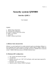
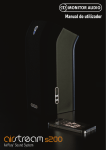
(3) FILTER (BLUE) :- _______________________________________________________________
In the 'FILTER OFF' position, the instrument's frequency response is flat to above 1KHz.
With the 'FILTER ON', the frequency response is -3dB @ 500Hz. This specification corresponds to
ISO standard 5393 - 1994 ‘Rotary tools for threaded fasteners - Performance test method’.
FREQUENCY
RESPONSE
AT
TE
NU
ATI
ON
(dB
)
10
0
-10
-20
-30
-40
-50
-60
-70
FILTER OFF
FILTER ON
0
500
1000
2000
4000
FREQUENCY (Hz)
(4) 'TRACK / MEMORY' SWITCH (PARCHMENT & ORANGE) :- ____________________________
In ' TRACK ' the display follows the transducer's output signal. This is generally used for calibration.
Selecting the 'MEMORY' mode causes the display to retain the peak value experienced by the
transducer. This mode is useful for testing dial type wrenches and power tools.
The TWA features an analogue memory to ensure fast capture of the peak value, together with digital
hold to give infinite storage.
(5) 'MEMORY RESET' SWITCH (PARCHMENT) :- _______________________________________
Press to reset the memory when in the 'MEMORY' mode. On reset the memorised value is output via
the RS-232-C connector.
(6) 'MEMORY AND AUTO RESET' SWITCHES (ORANGE) :-_______________________________
Pressing 'MEMORY' and 'AUTO RESET' switches simultaneously selects memory auto reset mode.
In this mode the TWA holds and displays the first peak of torque. When a peak is detected all
following peaks are ignored until the memory resets. The ‘STOP’ legend will flash and bleep tone
sound to give a visual and audible indication to the operator to stop loading. Reset is automatic after
a set hold time, this is settable to 1,2,3 or 4 seconds, see internal settings on page 21.
During the cycle the memorised value is output via the RS-232-C connector.
The memory auto reset mode is used primarily intended for testing preset (click) torque wrenches and
torque screwdrivers.
This mode is used in conjunction with the 'AUTO RESET TRIGGER LEVEL % OF FULL SCALE'
knob (7), see following description for it's function.
TWA OPERATORS HANDBOOK
PAGE 8 OF 28
ISSUE 9.0
OCT 1998
(7) 'AUTO RESET TRIGGER LEVEL % OF FULL SCALE' (ORANGE) :- ______________________
The trigger level setting is used to adjust the sensitivity of the memory auto reset mode that was
discussed in (6) on the previous page. It dictates the amount (as a % of TWA full scale) by which the
torque must fall below the peak torque for the peak torque to be held and the auto reset to operate.
By setting it is possible to ignore small ranging torque peaks in the transducer’s signal in preference to
the required larger peak.
When the trigger level is set to a low value (e.g. 0.7%) the auto reset will trigger on a small torque
peak.
When set to a higher value (e.g. 10%) the auto reset will trigger on a larger peak, ignoring smaller
peaks.
The setting is analogue, so allowing for infinite setting resolution within the allowable range.
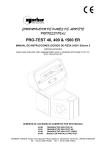
As an example of the trigger level setting, the operation of a torque wrench is explained in the graph
below and guide on the opposite page.
GRAPH showing capture of FIRST PEAK OF TORQUE in memory, when a preset (click) type torque
wrench is being tested with the TWA in the 'memory auto reset mode'.
TWA OPERATORS HANDBOOK
PAGE 9 OF 28
ISSUE 9.0
OCT 1998
TRIGGER LEVEL SETTING :-________________________________________________________
The trigger level only needs to be set when using the auto-reset mode. The following is a guide to it's
setting.
General rule for setting trigger level for testing preset (click type) torque wrenches : 1. Note the torque WRENCH MAX CAPACITY .
2. Note the TRANSDUCER FULL SCALE VALUE.
E.g : for a TWA 10
TWA 100
TWA 1000
TWA 2800
TRANSDUCER FULL SCALE = 10
TRANSDUCER FULL SCALE = 100
TRANSDUCER FULL SCALE = 1000
TRANSDUCER FULL SCALE = 3000
3. Calculate the WRENCH MAX CAPACITY as a percentage (%) of the TRANSDUCER FULL
SCALE.
%=
WRENCH MAX CAPACITY
TRANSDUCER FULL SCALE
x 100%
4. Having found the percentage (%) use the following graph to set the trigger level.
The above is only a guide and because different wrenches have different operating characteristics, it
may be necessary to try alternative trigger level settings to obtain consistent results. This will be
particularly true for very large and very small torque wrenches, and torque screwdrivers.
If obtaining incorrect readings, check wrench setting and operation.
If the auto reset triggers before expected value, set trigger level higher.
If the auto reset does not trigger at click of wrench, set trigger level lower.
TWA OPERATORS HANDBOOK
PAGE 10 OF 28
ISSUE 9.0
OCT 1998
TWA FUNCTIONS - BACK PANEL
1
SERIAL No.
MODEL No.
8
ZERO
ADJUS
T
7
3
ON
RS.232.C.OUT
PUT
6
OF
F
INTERN
BATTE
AL
RY
2
FUSE- T1 6 0 m A
MAX POWER 250v
6 W5 0 - 6 0
Hz
MADE IN ENGLAND BY NORBAR TORQUE TOOLS LTD
4
5
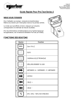
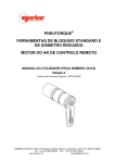
(1) INSTRUMENT IDENTIFICATION : - _________________________________________________
Each TWA has an individual serial number and a model number, which is the same as the Norbar
order part number for the particular model. ( NOTE : If the serial number or model number is
intentionally tampered with any warranty may be void).
(2) TRANSDUCER CABLE :- _________________________________________________________
Permanently connected (hard wired).
(3) ZERO ADJUST :- ________________________________________________________________
Adjust 'ZERO ADJUST' knob to give zero on display for no torque applied to transducer.
NOTE:- The TWA must be in the TRACK mode when adjusting for zero.
TWA OPERATORS HANDBOOK
PAGE 11 OF 28
ISSUE 9.0
OCT 1998
(4) 'INTERNAL BATTERY ON / OFF' SWITCH :- _________________________________________
The switch is only fitted to instruments that have an optional internal battery pack. If an AC voltage is
not connected to the instrument, or the mains switch (8) is 'OFF', this switch turns the instrument ON /
OFF. When an AC voltage is connected and the mains switch (8) is 'ON', this switch is not functional.
(5) 'RS-232-C OUTPUT' SERIAL INTERFACE :- _________________________________________
The RS-232-C output connector is a 9 way 'D' type socket. See page 12 for specification.
(6) VOLTAGE SELECTION AND FUSE HOLDER DRAWER :- _____________________________
Drawer orientation indicates 110/120 or 220/240 V AC mains input. Remove, turn through 180° and
reinsert drawer to alter voltage selection. To remove the drawer, firstly remove the mains lead, then
place a small screwdriver into the slot at the top of the drawer and gently lever open. The drawer
contains two fuses, one for 110/120V and one for 220/240V operation. Both are 160mA anti-surge
fuses.
The fuse for the selected voltage is located on the right hand side of the drawer as it is removed.
Always replace fuses with the same value and type of fuses as originally fitted.
(7) POWER INPUT :- _______________________________________________________________
Standard IEC type plug inlet with integral mains filter for use with mains cable supplied.
WARNING!
IT IS IMPORTANT THAT LIVE, NEUTRAL AND EARTH ARE ALL CONNECTED
BETWEEN THE TWA AND MAINS SUPPLY. IF NO EARTH IS AVAILABLE (2 WIRE
MAINS SUPPLY) IT IS RECOMMENDED THAT A SEPARATE EARTH IS
CONNECTED BETWEEN THE INSTRUMENT CASE (THE BOTTOM RIGHT HAND
FIXING SCREW IN THE CORNER OF THE BACK PANEL IS IDEAL) AND A
SUITABLE EARTH. ALTERNATIVELY THE INSTRUMENT COULD BE POWERED
BY BATTERY.
(8) MAINS SWITCH :- _______________________________________________________________
Turns TWA on / off.
TWA OPERATORS HANDBOOK
PAGE 12 OF 28
ISSUE 9.0
OCT 1998
RS-232-C SERIAL DATA OUTPUT INTERFACE
The RS-232-C output socket is a 9 way 'D' type mounted on the back panel of the TWA.
Output of both measured value and units of measurement (as shown on the display) are in a familiar
serial data format for communication with computers, printers, etc.
Data is output on the RS-232-C interface when the 'request to send' (pin 7 on output socket) is taken
HIGH, automatically when the memory auto-reset mode timer operates or when the 'MEMORY
RESET' button is pressed. Output can be triggered by pressing ‘MEMORY RESET’ in track and
memory modes.
RS-232-C INTERFACE SPECIFICATIONS :- ____________________________________________
Control Word
- Parity odd, even or off.
- 7 or 8 data bits.
- 1 or 2 stop bits.
Data rate fixed at 1200 baud.
Maximum of 5 data stream outputs per second.
Option for having a ‘blank’ or ‘+’ character at start of data stream.
Units of measurement can be selected to be output or inhibited.
Maximum number of characters per line is 17.
Transmitted data voltage levels +9 volts to -9 volts.
Print signal, HIGH to print +3 volts to +20 volts DC.
NOTE :- All options shown are internally selectable, refer to page 21.
Options are initially factory set to 8 data bits, 2 stop bits, no parity and no leading ‘+’ character.
RS-232-C OUTPUT PIN CONNECTIONS :-______________________________________________
PIN No
1
NOTE:
FUNCTION
Arm LED for print inhibit option.
2
No connection.
3
Transmitted data (from TWA).
4
Mode switch for print inhibit option.
5
Signal ground 0V.
6
Arm switch for print inhibit option.
7
Request to send (To TWA).
8
+ 5 volts (from TWA). WARNING: Not for powering external devices.
9
+ 10 volts (from TWA). WARNING: Not for powering external devices.
If Pin 9 is shorted to Pin 7 (via a momentary switch) data will be transmitted on Pin 3 each
time the switch is made and released. Up to 5 outputs per second can be requested in this
way.
TWA OPERATORS HANDBOOK
PAGE 13 OF 28
ISSUE 9.0
OCT 1998
RS-232-C DATA OUTPUT EXAMPLES :- _______________________________________________
Code : DP=Decimal Point.
CR=Carriage Return.
SP=SPace.
1. Using TWA 1000 set to the standard data string. Reading 864.45 Nm.
8
6
4
DP
4
5
SP
N
SP
m
SP
SP
SP
SP
SP
SP
SP
CR
CR
2. Using TWA 2800 set to the standard data string. Reading 26505 lbf.in.
2
6
5
0
5
SP
l
b
f
SP
i
n
3. Using TWA 100, with modified data string giving a ‘+’ at the start and no units of measurement.
Reading 34.227 N.m.
+
3
4
DP
2
2
7
CR
For RS-232-C trouble shooting see page 26.
MITUTOYO DATA PROCESSORS :- __________________________________________________
The instrument can be configured to communicate to Mitutoyo DP3DX, DP7, QM1000 and QM5000
families of data processors. This is selected by internal switches, see page 21.
For DP3DX, DP7, QM1000 and QM5000 families, the units of measurement must be inhibited, (set
switch 2-3 to ON).
For DP3DX and DP7 families, a '+' character must be added to the start of the data stream, (set
switch 5-5 to ON). This is in addition to switch 2-3.
WIRING THE TWA TO A DP3DX or DP7 DATA PROCESSOR :TWA RS-232-C
OUTPUT
CONNECTOR
COVER
PIN 3
PIN 5
MITUTOYO DP7
RS-232-C INPUT
CABLE SCREEN
PIN 3
PIN 7
LINK PINS 1 AND 5
LINK PINS 4 AND 8
WIRING THE TWA TO A QM1000 or QM5000 DATA PROCESSOR :TWA RS-232-C
OUTPUT
CONNECTOR
COVER
PIN 3
PIN 5
MITUTOYO QM5000
RS-232-C INPUT
CABLE SCREEN
PIN 3
PIN 7
LINK PINS 4 AND 5
LINK PINS 6 AND 8
For more information please consult your Mitutoyo data processor manual.
TWA OPERATORS HANDBOOK
PAGE 14 OF 28
ISSUE 9.0
OCT 1998
TRANSDUCER, TRANSDUCER HOUSING AND MOUNTING
INSTRUCTIONS
All TWA transducer shafts are robustly constructed from precision machined and heat-treated
specialised stainless steel onto which strain gauges are bonded in the form of a Wheatstone Bridge.
These strain gauges vary their electrical resistance in direct proportion to the strain produced in the
steel shaft by the applied torque. This small change in resistance causes a change in voltage across
the strain gauges, which is amplified within the TWA display unit.
The gauges are bonded to the shaft in a configuration that ignores bending moments and other
forces, and only responds to the true torque applied. The gauge configuration also helps in
maintaining temperature stability.
The TWA display unit provides a highly stable constant current supply to the strain gauge bridge for
accuracy.
TWA transducers are mounted in aluminium housings with steel reaction plates. The housings can
be mounted in either a horizontal or vertical position.
TWA 10 and TWA 100 housings have two mounting holes of 8.4 mm diameter (21/64 inch).
TWA 1000 and TWA 2800 housings have two 10.4 mm diameter (13/32 inch) holes for horizontal
mounting and four M8 taped holes in the reaction plate for vertical mounting.
TWA OPERATORS HANDBOOK
PAGE 15 OF 28
ISSUE 9.0
OCT 1998
TRANSDUCER HOUSING LABEL
This shows the correct mode of operation for testing the specified types of torque wrenches and
power tools shown. The colours of the instruction boxes are directly related to the colours associated
with the front panel controls of the instrument.
TWA OPERATORS HANDBOOK
PAGE 16 OF 28
ISSUE 9.0
OCT 1998
TWA OPERATING INSTRUCTIONS
1.
Securely mount the transducer.
2.
There are two possible ways to power the TWA :-
3.
a)
110/120 V or 220/240 V AC MAINS
Ensure voltage selector draw at the rear of the instrument is correctly positioned for your
mains supply.
Connect AC mains lead and switch power 'ON' at rear.
b)
INTERNAL BATTERY PACK OPTION
If fitted, the TWA can be used without an external connection. The TWA rear mains switch
is not functional with this option, so a battery ON / OFF switch is fitted to the back panel.
Switch instrument 'ON', wait 2 seconds for initialisation.
Allow 5 minutes for the instrument to warm up and stabilise.
4.
Select required units of measurement. Pressing the select units switch once will step onto the
next available units of measurement.
5.
If the display does not read zero, the zero control on the back panel will need to be adjusted.
Firstly, select ‘TRACK’ mode and exercise the transducer to full scale in direction of use to
overcome hysteresis.
Then adjust the ‘ZERO ADJUST’ on the back panel until zero is displayed.
5
SERIAL No.
MODEL No.
3
ZERO
ADJUS
T
ON
RS.232.C.OUT
PUT
OFF
INTERN
BATTER
AL
Y
MADE IN ENGLAND BY NORBAR TORQUE TOOLS LTD
2b
2a
FUSE- T1 6 0 m A
2MAX
5 0 v POWER 6 W5 0 - 6 0
Hz
TWA OPERATORS HANDBOOK
PAGE 17 OF 28
ISSUE 9.0
OCT 1998
OPERATING INSTRUCTIONS :- ______________________________________________________
6.
a)
Select mode of measurement required, i.e. Track, Memory or Memory Auto Reset.
Track - ‘TRACK / MEMORY’ switch out..
Memory - 'TRACK / MEMORY' switch in.
Memory Auto Reset - 'TRACK / MEMORY' and 'AUTO RESET' switches both in.
NOTE:b)
Ensure units are correctly selected for the capacity of the transducer.
If Memory Auto Reset is selected, set the 'AUTO RESET TRIGGER LEVEL % OF FULL
SCALE' knob to the required level.
7.
Select filter 'OFF' or 'ON' dependant on application.
See suggested applications on page 18.
8.
The digital display will show the applied measurement with the analogue trend bar being a
rapid reference to the torque applied.
The TWA is now ready for use. Please use the ‘OPERATING GUIDE’ label that is attached to the
instrument for everyday operating instructions.
NOTE : If direction of measurement application is reversed, torque the transducer to full scale in the
reverse direction and re-zero the display before taking any readings.
TWA OPERATORS HANDBOOK
PAGE 18 OF 28
ISSUE 9.0
OCT 1998
APPLICATIONS
The TWA has all the facilities to test and calibrate the numerous types of Torque Wrenches, Torque
Screwdrivers and Power Tools in use today.
A more detailed description of the instrument’s functions can be found on page 6 of this handbook , in
addition there is an operating guide label attached to the instrument.
Colour coding of mode selection is used on the front panel and transducer housing instruction label to
further ease operation.
Below is a summary of the main applications that the TWA has been designed for :PRESET (CLICK) WRENCHES :-______________________________________________________
INSTRUMENT MODE :
FUNCTION BUTTONS :
SET TRIGGER LEVEL :
FILTER SETTING :
First peak of torque memory.
‘MEMORY’ and ‘AUTO RESET’ both in.
YES.
Recommended ‘ON’ for stahlwillie
wrenches, ‘OFF’ for others.
This mode accurately captures the true operating point of the wrench.
If used in normal ‘MEMORY’ mode a possible over torque, caused by the operator loading the wrench
past the ‘click’ point, would be displayed.
For a full description of how to use this mode, see pages 6 to 9.
BENDING BEAM AND DIAL WRENCHES :- _____________________________________________
INSTRUMENT MODE :
FUNCTION BUTTONS :
SET TRIGGER LEVEL :
FILTER SETTING :
Peak memory.
‘MEMORY’ in.
NO.
Recommended ‘OFF’.
This mode is used to give the operator time to monitor both the reading on the wrench and the value
displayed on the TWA.
If the first peak of torque mode was used, then any operator hesitancy in reaching the desired torque
value could lead to an incorrect reading.
For a full description of how to use this mode, see pages 6 and 7.
TORQUE SCREWDRIVERS :- ________________________________________________________
INSTRUMENT MODE :
FUNCTION BUTTONS :
SET TRIGGER LEVEL :
FILTER SETTING :
First peak of torque memory.
‘MEMORY’ and ‘AUTO RESET’ both in.
YES.
Recommended ‘OFF’.
Inaccurate readings can be obtained when testing torque screwdrivers in the peak memory mode due
to the operating action associated with this type of tool.
For a full description of how to use this mode, see pages 6 to 9.
TWA OPERATORS HANDBOOK
PAGE 19 OF 28
ISSUE 9.0
OCT 1998
POWER TOOLS :- _________________________________________________________________
NOTE:- A rundown nose assembly option should be used when testing power tools on TWA’s.
Measuring torque output
from all types of power
tools.
Measuring the first (true)
peak of torque from dogclutch and ratcheting power
tools.
First peak of torque.
‘MEMORY’ and ‘AUTO RESET’
both in.
YES.
INSTRUMENT MODE :
FUNCTION BUTTONS :
Peak memory.
‘MEMORY’ in.
SET TRIGGER LEVEL :
NO.
FILTER SETTING :
Recommended ‘ON’
APPLICATION
For hydraulic, pneumatic and electric, stall type power tools in
accordance with ISO 5393 - 1994 specifications.
For testing other types of power tools, with frequency response
of the memory complying to BS 6268:1982 / ISO 6544:1981.
Recommended ‘OFF’
Shown below is a typical output for a clutch or ratchet type power tool.
These tools produce a high value fast torque spike after the first peak of torque has been reached.
This torque spike may be of a considerably higher torque than the first peak, but because it is high
frequency, low energy, narrow pulse, it will not significantly increase the tension in the fastener being
tightened.
Thus the TWA should be used in the 'MEMORY AUTO RESET' mode to capture the important first
peak of torque.
For full description of how to use this mode, see pages 6 to 9.
TWA OPERATORS HANDBOOK
PAGE 20 OF 28
ISSUE 9.0
OCT 1998
RUNDOWN NOSE ASSEMBLIES FOR POWER TOOL TESTING
The Norbar rundown nose assemblies used in conjunction with the Norbar Torque Wrench Analysers
(TWA) are designed to measure the torque output of power tools. This they do by simulating the
working conditions of screwed or bolted joints, to BS 6268 - 1982, ISO 6544 - 1981 and ISO 5393 1981 standards.
Washers can be arranged in various serial / parallel combinations to represent the working conditions
as seen by the tool, i.e. joints of varying stiffness ('soft' or 'hard' pull up) and for a range of maximum
torque outputs.
Stacks of washers with a long bolt are supplied to simulate soft pull-up joints over the range of the
TWA. A short bolt is used to simulate hard pull-up joints. By re-arranging the stacks of washers
intermediate pull-up conditions can be simulated.
Refer to individual rundown nose assembly data sheets for details of washer make-ups and graphs.
These data sheets and graphs are supplied when a particular size of rundown assembly is purchased.
RUNDOWN NOSE ASSEMBLY SPECIFICATIONS :-______________________________________
NOSE ASSEMBLY
PART No.
50185
50160
50186
50195
50163
51071
FOR USE WITH
TWA
TWA 10
TWA 100
TWA 100
TWA 1000
TWA 1000
TWA 1000
0.2-10
2-12
10-100
10-100
100-680
100-680
1.8-90
1.5-9.0
2-100
20-100
7.4-74
20-120
90-900
7.4-74
100-1000
7.4-74
100-1000
74-500
1000-6800
74-500
1000-6800
M6
SCREW
5.0
0.197
M6
SCREW
5.0
0.197
M12
SCREW
10.0
0.394
M12
SCREW
10.0
0.394
M24
SCREW
10.0
0.394
M24
SCREW
19.0
0.748
0.85
1.87
0.63
1.39
2.20
4.85
2.20
4.85
40.0
88.18
8.25
18.18
RANGE
N.m
ozf.ins
lbf.ins
lbf.ft
kgf.cm
SOCKET CAP
SCREW
ACROSS mm
FLATS inches
WEIGHT
Kg
lbs
TWA OPERATORS HANDBOOK
PAGE 21 OF 28
ISSUE 9.0
OCT 1998
INTERNAL USER SETTINGS
Only open the instrument to make changes that are essential.
WARNING! SWITCH OFF AND DISCONNECT ALL POWER TO THE TWA.
1
To access the switches remove the 4 screws that retain the lid (2 at the top of front panel and
2 at the top of rear panel). It will be necessary to loosen the 2 bottom screws of the front panel
by about one turn. The lid can be removed, along with the battery pack if fitted.
Due to human electrostatic discharge (ESD), do not touch components other than those required.
2.
Select settings as required, please refer to layout drawing on page 23. There is also
a switch setting diagram located on the mains inlet socket within the TWA.
SWITCH 1
1-1
1-2.
1-3.
1-4.
FUNCTION
Not for user selection, DO NOT CHANGE
Not for user selection, DO NOT CHANGE
Not for user selection, DO NOT CHANGE
Not for user selection, DO NOT CHANGE
OFF
FACTORY SET
ON
SWITCH 2
FUNCTION
OFF
ON
2-1.
RESOLUTION SELECTION (DIGITS)
Standard 5+1/2
Reduced 4+1/2
2-2.
Not for user selection, DO NOT CHANGE
2-3.
UNITS OF MEASUREMENT OUTPUT
WITH RS- 232-C CHARACTER STREAM
Output units
Inhibit units
2-4.
N.m
Disabled
Enabled
2-5.
dN.m
Disabled
Enabled
2-6.
cN.m
Disabled
Enabled
2-7.
lbf.ft
Disabled
Enabled
2-8.
lbf.ins
Disabled
Enabled
FACTORY SET
FACTORY SET
FACTORY SET
FACTORY SET
TWA OPERATORS HANDBOOK
PAGE 22 OF 28
ISSUE 9.0
OCT 1998
INTERNAL USER SETTINGS :- _______________________________________________________
SWITCH 3
FUNCTION
OFF
ON
3-1
ozf.ins
Disabled
Enabled
3-2
kgf.m
Disabled
Enabled
3-3
kgf.cm
Disabled
Enabled
3-4
gf.cm
Disabled
Enabled
SWITCH 5
5-1
FUNCTION
RS-232-C CONTROL WORD PARITY
OFF
EVEN
ON
ODD
5-2
RS-232-C CONTROL WORD PARITY
NO PARITY
PARITY ON
5-3
RS-232-C CONTROL WORD CHARACTER
LENGTH
8
7
5-4
RS-232-C CONTROL WORD STOP BITS
2
1
5-5
RS-232-C LEADING ‘+’ CHARACTER
INHIBIT +
OUTPUT +
5-6
Not for user selection, DO NOT CHANGE
FACTORY SET
5-7
AUTO RESET TIME (with 5-8), see below
STANDARD SET
5-8
AUTO RESET TIME (with 5-7), see below
STANDARD SET
3.
SWITCH 5-7
SWITCH 5-8
ON
ON
4 SECONDS
OFF
OFF
3 SECONDS
OFF
ON
2 SECONDS
ON
OFF
1 SECOND
Replace lid and screws before turning on.
TIME
TWA OPERATORS HANDBOOK
PAGE 23 OF 28
ISSUE 9.0
OCT 1998
INTERNAL USER SETTINGS :- ______________________________________________________
SWITCH LOCATIONS
FRONT OF TWA
TWA OPERATORS HANDBOOK
PAGE 24 OF 28
ISSUE 9.0
OCT 1998
INTERNAL BATTERY PACK OPTION
MODULE PART NUMBER 44032
The TWA internal battery pack is mounted in the lid of the instrument. Rechargeable nickel cadmium
cells are used, these are not user replaceable.
The battery pack will power the instrument for a minimum of 8 hours continuous use. Recharge time
is 16 hours.
To use the instrument on battery power, disconnect mains power and switch 'BATTERY ON / OFF' to
'ON' and select required operating mode, etc. When approximately half an hour battery power life is
left in the batteries a 'LO BATT' message will flash on the digital display. When battery output goes
below the voltage at which the instrument will not function correctly (out of calibration) the instrument
switches OFF automatically. Once batteries are discharged, switch the 'BATTERY ON / OFF' switch
to 'OFF'.
To recharge batteries connect the TWA to an AC mains supply (110/120 or 220/240 V AC) and switch
'Power On'. The TWA can be used as normal whilst batteries are charging. There is no maximum
charge time for the battery pack, so the TWA can be continuously used on mains without causing
damage to batteries.
Note :- If the TWA is charged for less than 16 hours or at a mains voltage of less than 110 VAC /
220 VAC then a reduced discharge duration may be expected.
To obtain maximum battery life and performance, It is highly recommended that battery
packs are used in a cycle of :FULLY DISCHARGE - FULLY CHARGE (minimum 16 hours) - FULLY DISCHARGE
TROUBLE SHOOTING :- ____________________________________________________________
If Battery Pack fails to power the TWA after recharging, check the two fuses protecting the batteries
that are mounted on the Battery Pack P.C.B. This is achieved by following the procedure below :WARNING!
SWITCH OFF THE TWA AND REMOVE THE POWER LEAD.
SWITCH THE BATTERY ON / OFF SWITCH TO THE OFF POSITION.
1.
Remove the two upper most cross head screws on the instrument's front and back panels (four
screws in all).
2.
Loosen the two lower cross head screws on the front panel half a turn.
3.
Lift off the instrument lid complete with the battery pack.
WARNING!
UNPLUG THE BATTERIES FROM THE BATTERY PACK P.C.B. BEFORE
ATTEMPTING TO REMOVE THE FUSES (500 MA ANTI-SURGE), AND
RECONNECT ONCE THE FUSES HAVE BEEN
REPLACED.
IF PROBLEMS ARE STILL INCURRED, RETURN TO NORBAR OR A NORBAR
APPOINTED AGENT, FOR EVALUATION.
TWA OPERATORS HANDBOOK
PAGE 25 OF 28
ISSUE 9.0
OCT 1998
PRINT INHIBIT CONTROLLER OPTION
PART NUMBER 60167
INTRODUCTION :- _________________________________________________________________
The print inhibit controller is a remote, hand held device for controlling the RS-232-C output from the
TWA. This option can be retro fitted to any TWA, model number 43150 - 43157.
This option can control unwanted RS-232-C data input to printers, calibration and data collection
systems.
The function of this device is to either :
(i) Allow RS-232-C data output as normal, so giving data on each request.
(ii) Completely disable RS-232-C data output.
(iii) Only to allow data RS-232-C output on the next request and inhibit all subsequent requests.
OPERATION :- ____________________________________________________________________
Position of ' PRINT NORMALLY/ PRINT WHEN ARMED’ switch :SWITCH
POSITION
'PRINT
NORMALLY'
'PRINT WHEN
ARMED’
‘PRINT WHEN
ARMED’
STATE OF
INDICATOR
UNARMED
UNARMED
ARMED
(Having
pressed
button on
controller)
ACTION
The RS-232-C output acts as normal.
Every time an output is requested it will be issued.
The RS-232-C output is inhibited, so will not function.
When the ' ARM ' button is pressed, the arm led will light
so indicating that the next request to send data will be acted
upon.
Upon the next data output taking place, the arm led will turn
off and the RS-232-C output will again be inhibited.
To obtain further data output either press the ‘ARM’ button
or switch to ‘PRINT NORMALLY’.
TWA OPERATORS HANDBOOK
PAGE 26 OF 28
ISSUE 9.0
OCT 1998
TWA TROUBLE SHOOTING
1.
Instrument does not power up.
a)
b)
c)
2.
Check the Voltage Selector drawer is in the correct orientation for your mains supply.
Check fuse in the voltage selector drawer (on the right hand side as draw is removed).
Check fuse in mains plug.
Displayed user error messages.
These error messages will be displayed on the TWA front panel display if the following errors
occur : a)
b)
c)
d)
3.
Required units of measurement are not selectable
a)
b)
4.
Conversion from transducer standard units to required units could not be displayed within
available digits on display, thus conversion is not allowed.
Units required have not been enabled. See page 21.
RS-232-C data output not communicating with other equipment
a)
b)
c)
d)
5.
'ERROR 27 - OVERANGE' : The transducer may have been taken into an overload state.
'ERROR 29 - TOO BIG' : Illegal units of measurement selected for transducer connected.
Step to next conversion with select units switch.
'ERROR 30 - TOO SMALL' : Illegal units of measurement selected for transducer
connected. Step to next conversion with select units switch.
'ERROR 33 - FIRMWARE' : Switch power to instrument ‘OFF’, then ‘ON’ again at the rear
of the TWA. If message does not clear, return the TWA to Norbar for evaluation.
Check that control word on the TWA and the equipment receiving data match. See page 21.
Check that the baud rate is set to 1200 baud on the equipment receiving data.
Check that the connecting lead is wired correctly at both ends, see page 12.
Check if equipment receiving data requires the units of measurement inhibited or a leading
character. This is applicable when interfacing to Mitutoyo equipment, see page 13.
Battery pack option
If the battery pack option fails to power the instrument after recharging, check the two fuses
protecting the batteries, these are mounted on the battery pack board. To complete this
task refer to the trouble shooting section of the integral battery pack option on page 24.
6.
Display values changes when transducer cable is moved.
This could be caused by broken or loose wires in the transducer lead.
7.
Display will not zero, with no torque applied to the transducer.
Check the relationship of the transducer input square drive to the output square drive, the
sides must be parallel. If they are not the transducer has been overstrained and may require
recalibration or replacement.
8.
Recalibration of TWA
If there is any doubt concerning the functionality or accuracy of the instrument it should be
returned to Norbar, or a Norbar appointed agent for repair and / or recalibration.
TWA OPERATORS HANDBOOK
PAGE 27 OF 28
ISSUE 9.0
OCT 1998
This page left intentionally blank
TWA OPERATORS HANDBOOK
PAGE 28 OF 28
ISSUE 9.0
OCT 1998
INDEX
PAGE
Applications - Bending Beam & Dial Wrenches
Applications - Power Tools
Applications - Preset (click) Wrenches
Applications - Torque Screwdrivers
Auto Reset Trigger Level % of full Scale
18
19
18
18
8
Cleaning
Display
Filter
2
6
7
Instrument Identification
Internal Battery On/Off Switch
Internal Battery Pack - Trouble Shooting
10
11
24
Mains Plug Fitting
Mains Switch
Memory and Auto Reset Switches
Memory Reset Switch
Mitutoyo Data Processors
2
11
7
7
13
Norbar Torque Wrench and Power Tool Analyser
3
Optional Extras
1
Power Input
Print Inhibit Controller - Introduction
Print Inhibit Controller - Operation
Print Inhibit Controller - Typical Applications
11
25
25
25
RS-232-C Data Output Examples
RS-232-C Interface Specifications
RS-232-C Output Pin Connections
Rundown Nose Assembly Specifications
13
12
12
20
Select Unit Switch
6
Track/Memory Switch
Transducer Cable
Trigger Level Setting
TWA Calibration and Repair
7
10
9
2
Voltage Selection and Fuse Holder Draw
11
Zero Adjust
10