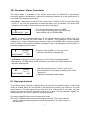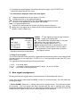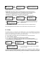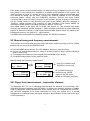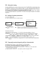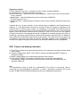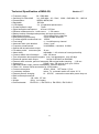
1
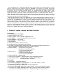
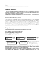
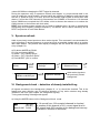
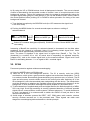
Memory Radio Analyser MRA-5Q User Manual Read this manual before use. Version Q1.7 The new MRA-5Q is an advanced automatic radio scanner suited for instant detection of various types of radio bugs in the frequency range 34–5900MHz. The basis of the system is the radio spectrum memory combined with an ultrafast scanning. The whole frequency range is scanned every 10 seconds and the currently received signals are compared with the initially stored „clean“ background spectrum. The presence of a new signal activates a three level alarm output. All new signals with frequency, time and a statistic information are stored in an independent alarm memory. MRA-5Q allows to automatically acquire audio records of new signals which have been causing alarms. Recorded audio samples together with the stored statistic information are reliably indicating if the object was attacked by RF eavesdropping. MRA-5Q can be used as a part of the QM-5000 bus system. QM-5000 allows parallel connection of up to 127 MRA-5Q devices within an object network. The bus system allows full remote control of each device, and additionally it contains numerous additional features like spectrum analysis in the range of 34–5900MHz, audio signal analysis, background statistic, new signal statistic, automatic audio sampling, frequency and spectrum records, selective statistic, system statistic etc. QM-5000 is not only a comprehensive solution for object permanent protection, but also a very effective tool for electronic countermeasures specialists since it gives a clear graphical picture of the current RF signals. By using QM-5000 we can detect and record even such dangerous systems like spread spectrum, or modified WiFi, DECT, UMTS and GSM etc. I. Controls, inputs, outputs and their function Front panel: 1. 2 x 16 character LCD display 2. Switch POWER: ON / OFF 3. Switch AUDIO: ON = internal loudspeaker ON 4. Knob AUDIO: internal loudspeaker volume control 5. Knob SEARCH: fine tuning 6. Button MODE: function switch 7. Button MENU: a) short push = switch to manual tuning b) in manual tuning = frequency measurement c) long push in modes SCAN, Background and New Signal activates context menu, user is navigated by displayed instruction to other functions 8. Button DOWN (-): a) frequency tuning down b) memory records listing down c) other context selections 9. Button UP (+): a) frequency tuning up b) memory records listing up c) other context selections 10. Green LED ON: indicator ON 11. Yellow LED CHARGE: external power supply and battery charge 12. Red LED ALARM: a) flashing each 10 sec. = PRE-ALARM b) continues light = ALARM Rear panel: 13. ANTENNA telescopic antenna 14. Connector CHARGER: external power 12 – 25 V DC, centre = + pole 15. Connector PHONES, ALARM LED: a) earphones 2 x 32 ohm, disconnect internal loudspeaker b) external LED ALARM output: 2mA, right channel = -pole, stereo ground = +pole 16. Connector OPTIONS: QM4000 system bus or audio recorder interface SCAN-R. Left channel = +RS485, right channel = -RS485, stereo ground = line audio 2 Bottom: 17. Trimmer GAIN: antenna attenuation, maximum = clock-wise II. MRA-5Q adjustment Push out the antenna and place the MRA-5Q in the room in such place to avoid direct contact with persons sitting or walking in the room. For long term usage connect the power supply adapter, indicated by yellow LED CHARGE. Frequencies over 4500MHz are received by narrow slot in the bottom lid. This slot should not be covered by electric conductive subjects. III. Power ON and battery check After switching on (the POWER switch) the green POWER LED lights up, the red ALARM LED flashes shortly and the LCD displays the software version and language (EN = English version). If the AUDIO is ON the loudspeaker is tested. A weak battery (bellow 7V) is indicated by BATT! message in the bottom line of the LCD. A weak battery must be changed as soon as possible. If the battery is very weak (bellow 6.5V) the device cannot be switched ON. When the device is used with external power supply DO NOT USE non-rechargeable alkaline batteries! Preferably use NiMH or NiCd accumulators. IV. Spectrum entry Erases old content of the spectrum memory and makes the new record a) Use the MODE button to set the SCAN mode b) Push the MENU button for several seconds c) Select + (UP) “Modify spectr.” d) Select – (DOWN) “Spectrum Entry” e) Push MODE: “yes” to confirm SCAN MENU >2sec. Spectrum Entry? MENU:no MODE:yes +:Modify spektr. -:Settings MODE UP (+) Spectrum Entry +:Spectrum Refre -:Spectrum Entry DOWN (-) Erases the old background spectrum and makes a new background record It is recommended to switch AUDIO-ON because in the second phase of “Spectrum entry” all the recorded frequencies are automatically tuned up for an instant. The user can hear the local radio background. During this process the display is signaling: BackG = signal strength of recorded signal in the background, S = instant signal strength. In the third phase of “Spectrum entry” all DECT frequencies are checked (if function “correct DECT” is active see chapter XIV.). The display is signaling xxx 000 000 yyy, if the 3 values 000 000 are changing the DECT signal is detected. During the spectrum entry or spectrum refresh (see chapter V.) people should walk in the room to imitate the usual situation. Human bodies are reflecting or damping radio waves and the aim of spectrum entry is to store as much as possible legal signals to avoid later false alarms. If more then 350 channels for frequencies over 330MHz or more then 110 channels below 330MHz are occupied the LCD shows a hint to shorten the antenna or to reduce the GAIN (trimmer on the bottom anti-clock-wise). DECT: this wireless system should not be used in protected area, its base is permanently transmitting and irregularly changes frequency. The MRA-5 has to reduce sensitivity for all DECT frequencies to avoid false alarms. V. Spectrum refresh Adds to previously stored spectrum other active signals. This command is recommended for quick recording of varying spectrum to record as much as possible signals and so to reduce later false alarms. The process and display messages are the same like during Spectrum entry (chapter IV). a) By button MODE set SCAN b) Long push button MENU c) Select + (UP) “Modify spectr.” d) Select + (UP) “Spectrum Refre” e) Push MODE: “yes” to confirm SCAN MENU >2sec. Spectrum Refresh MENU:no MODE:yes +:Modify spektr. -:Settings MODE UP (+) Spectrum Refresh +:Spectrum Refre -:Spectrum Entry UP (+) Adds active signals to the previously stored background VI. Background check – detection of already installed bug All signals recorded in the background (chapter IV. or V.) should be checked. This is the fastest and most effective way of selective detection of any active wireless bug already installed in the room (see chapter XVI. dangerous signals). Tuning and checking of background signals: a) Using the MODE button set the Background check mode The 1th record from 124 occupied channels is checked 001/124 The number of this channel is 041, current signal level is (chn 041) 062, signal level 065 is written in the background memory BackG=065 S=062 (indication in brackets is alternated) 4 b) By using the UP or DOWN buttons check all background channels. The current channel number is alternated by the sequential number of channel / sum of occupied channels in the background memory. During the background check the system is automatically tuning the strongest signal when going to a new channel. If you use the SEARCH knob, return it back to the central position before pushing UP or DOWN to allow symmetric fine tuning of the next background channel. c) Tune the best reception by the SEARCH knob (the LCD measures the signal level in the DIST area) d) Pushing the MENU button for several seconds opens a submenu: editing of selected channel chn 041 BackG=065 S=062 MENU >2sec Edit BG? MENU:no MODE:yes UP Edit BG 041 MODE BackG=065 S=062 Button UP increases background (BackG), DOWN decreases. Button MODE confirms new setting Increasing of BackG the sensitivity for selected channel is decreased, but the false alarm resistance for this channel is increased. Value S is indicating instant signal level. Value BackG should be approximately the same like the S level. Note: The alarm is signalled if the signal level is higher than (BackG + TH). The TH (threshold) is a number 20 to 100, its actual level is depending on adjusted sensitivity (chapter XIV.), and on the instant signal level on the scanned channel. Signal level S and BackG is alternating between: 0 = no signal to 240 = maximal signal. VII. SCAN Permanent protection against wireless eavesdropping. a) Using the MODE button set SCAN mode b) Note the ID of the last background #XXXX. The ID is security code has 65536 combinations, which gives a good protection against non-authorised manipulation. The ID is a random number automatically generated during any spectrum entry or refresh. The ID code and all memory records remain stored in the memory also after switching off. If the ID is changed it is sure that somebody was manipulating with the device. The manipulation could be caused by an attacker who installed a bug and programmed its frequency to the background. In such a situation a background check (chapter VI.) should be done. c) To allow detection of sophisticated pulse and digital devices the default sensitivity of MRA5Q is very high. Such high sensitivity is causing unwanted detection of different sporadic signals like air communication, mobile systems, different pulses etc. To avoid disturbance by such “pre-alarms” it is recommended to switch the AUDIO off and just time to time check the ALARM LED. d) Avoid usage of wireless systems like DECT, WiFi, GSM gates, radio controls, wireless security, wireless cameras etc. in the protected area. Those signals can mask most dangerous eavesdropping devices based on a similar principle. 5 VIII. Pre-alarm, Alarm, Past-alarm The alarm status is indicated in the SCAN mode when the MRA-5Q is permanently protecting against eavesdropping. Alarms are caused by detection of a new signal which is not stored in the background memory. - Pre-alarm: a short flash of red LED and a short beep if AUDIO is ON. In the bottom right corner of the LCD the percentage of achieved alarm level is indicated. The alarm level increases in the case of continuous presence of the new signal. SCAN #C05B 48% -ID of the last background record is C05B -A new signal is reaching 48% of the alarm limit (status below 100% is PREALARM) - Alarm: the alarm is activated when any of new signals reaches 100% of alarm level. The default time for reaching the 100% alarm is 10 minutes. This parameter can be adjusted (chapter XV.). Alarm is indicated by continuous light of red ALARM LED, continuous audio tone (if AUDIO is ON) and the ALARM! message on the LCD alternated by the duration of the alarm HH:MM (hours:minutes). ALARM! ( 01:07 ) SCAN #C05B 100% - Duration of the ALARM is 1 hour and 7 min. (indication in brackets is alternating) - Past-alarm: indicated in the top right corner of the LCD by message ALARM! alternated by -HH:MM which is time information how many hours:minutes ago the last alarm has stopped ALARM! (-47:17 ) SCAN #C05B 22% - Last alarm stopped before 47 hours and 17 min. - At the same time a new signal is reaching 22% of the alarm limit - (indication in brackets is alternating) IX. New signal check This function allows checking of signals which are causing or caused an alarm. In the SCAN mode all signals which are not stored in the background memory are written to the new signal memory. The new signal memory can store up to 100 records. If more than 100 new signals are received the less important records are erased. The less important signals are usually sporadic, very weak, caused by electric pulses etc. a) Using the MODE button set the “New signal” mode b) By UP or DOWN buttons check all new signal channels. The current channel number is alternated by sequential number of the channel / the total number of new channels 6 c) If a dangerous signal appears, disconnect the power supply, see LCD DIST and find the strongest signal in the room. - The information displayed about each new signal: S highest recorded level of a new signal (0 to 240) B background level on the displayed channel SM the sum of new signal activity time DD:HH:MM (days:hours:minutes) L the time of last appearance of the signal -DD:HH:MM XX% % of achieved alarm limit before XX% informs that this channel caused an alarm in the past before XX% this signal has an audio record in the connected recorder (see SCANr mode in chapter XI.) New signal (S=117 B=010 (SM=00:12:35 (L= -00:00:00 002/023 (chn 480 ) 56% 56%) 56%) 56%) 002/023 2nd new signal from total 23 new channels chn 480 signal is on channel 480 this channel has caused an alarm in the past 56% alarm level in the last scan cycle S=117 max. recorded signal level = 117 B=010 background level of channel 480 is = 010 SM sum of this channel activity 12 hours 35min. L last appearance of the signal before 0d,0h,0m (this signal is active) (indication in brackets is alternating) - Listing of new signals: The current channel number (chnXXX) is alternated by sequential number of the channel and the total number of new channels YYY/ZZZ (YYY is the sequential number and ZZZ is the total number). The signals are listed according to following priorities: 1. XX% % of actual alarm. 2. or information that the signal caused an alarm (see XI. SCANr) 3. SM sum of time of the signal activity X. New signal management Working with the new signal memory and optimization of the background memory. In the “New signal” mode push the MENU button for several seconds. The LCD offers the following selection: - (button DOWN) “Delete all”, it means erase all new signal records. This instruction should be executed if all new signals had been checked and the user is satisfied with already programmed background spectrum (no false alarms). Erasing of all new signals ensures that during next new signal revision only the actual signals will be displayed. 7 New signal MENU >2sec +: Edit -: Delete all DOWN (-) Delete all ? MENU:no MODE:yes +(button UP) Edit offers following options: +(button UP) “Add to BG”, adds the selected channel and information about its signal level into the background (value “B”-background level is increased to level “S” from the new signal memory). It is recommended to add legal signals (broadcast, TV, GSM, BTS etc.) which have a high SM value. First check the signals marked or which have caused alarms in the past. chn 305 New signal MENU >2sec Add to BG ? MENU:no MODE:yes +: Edit -: Delete all MODE UP (+) +:Add to BG -:Delete record UP (+) Level B of the channel 305 in the background memory is increased to level S from the new signal memory - (button DOWN) “Delete record”, erase this channel from the new signal memory. Note: pushing different buttons than the menu offers returns to the previous mode. XI. SCANr The SCANr mode is an extension of the SCAN mode. In this mode MRA-5Q automatically records audio samples of alarm signals. This allows detection of time delayed bugs and in particular an expert analyses at any time after a VIP meeting. a) b) c) d) In the SCAN or the SCANr mode push the MENU button for several seconds – (button DOWN) “Settings” + or - (button UP or DOWN) select SCANr and push MODE + or - (button UP or DOWN) are setting the length of audio sample recording: off = SCANr is off. 010, 020, 030, 040, 050, 060 = time of audio samples in seconds. e) Confirm selected time by MODE button SCAN MENU >2sec +:SCANr off or time MENU:no MODE:yes +:Modify spectr. -:Settings DOWN (-) by + or select SCANr MODE UP or DOWN are setting length of audio samples, confirm by MODE If SCANr is off the permanent protection (section VII) is indicated as SCAN. SCANr is activated if any time 10–60s is selected. In SCANr all functions are equivalent to the SCAN mode, but additionally the signals causing alarm are recorded on connected audio recorder. 8 Each audio record has the selected length (10–60s) and if any of signals is active for a long time period its next records are repeated in a random period between 5–25 minutes. For audio recording any type of recorder with VOX (voice activated), external microphone input and external 3V power can be used. Connect the SCAN-R adapter to the OPTIONS connector (stereo 3.5mm) and the CHARGER connector. Connect the mono 3.5mm connector and a small 3V power connector to the recorder. Set the recorder to VOX mode, set the SCANr mode on the MRA-5Q and push button MENU. MRA-5Q switches to “M.tuning”. Adjust recorder VOX sensitivity to start recording. Push button MODE for returning to SCANr and the recording must stop in approx. 3 sec. time. New signal history is the same like in SCAN, see section IX. The channels with audio record(s) are marked by symbol instead . Check all audio records and compare them with signals on channels marked . Legal signals causing false alarms should be added to the background memory, see section X. – next selection. If the MRA-5Q is connected to the QM5000 system, the SCANr is disabled! XII. Manual tuning and frequency measurement This function can be activated from any mode and allows frequency tuning by UP or DOWN buttons and fine tuning by the SEARCH knob. a) Push the MENU button shortly. The LCD displays “M.tuning” (manual tuning). b) Use the UP and DOWN buttons for tuning in a wide frequency range. Use the SEARCH knob for fine tuning. c) To measure the frequency of tuned signal push the MENU button shortly d) The MODE button returns to the previous mode Manual tuning and frequency measurement: any MODE chn XXX M.tuning NNNN MENU M.tuning chn XXX NNNN chn XXX F= 325.8MHz tune UP or DOWN, knob SEARCH is fine tuning UP or DOWN returns to manual tuning, MODE returns to the last mode MENU re-measures frequency XIII. Signal level measurement – transmitter distance The bargraph DIST 50–1m is indicating approximately the distance of a transmitter 100– 2000 MHz effectively radiating 1mW RF power. In practice the radiation efficiency of hidden bugs is problematic and the declared RF power usually does not correspond with real ERP. Use the DIST bargraph for an exact localization of a bug, see section IX.c). In modes background or new signal check the signal strength is also indicated S=000 (minimum) up to S=240 (maximum). 9 XIV. Automatic tuning Using the MODE button to set the “Autom.tuning” mode. The MRA-5Q is automatically tuning at a speed of 40s per the whole frequency range. At each signal the tuning stops for 4 seconds. For searching more or for listening to the signal push the MENU button to activate the manual tuning. The MODE button returns back to automatic tuning. The automatic tuning function is designed specifically for security officers who provide permanent physical spectrum supervision. For better uninterrupted reception use external earphones. XV. Setting of system parameters a) Set the SCAN mode b) Push the MENU button for several seconds by buttons +/- select: SCAN MENU >2sec use MODE to to select required option Alarm time Sensitivity DOWN Correct DECT SCANr (-) Bus ID +:Modify spectr. -:Settings Buttons +/- are setting required parameters, button MODE confirms required setting and returns to SCAN Selectable parameters: -Alarm time (pre-alarm period): 1, 5, 10, 20, 30, 40 minutes (default = 10 min.) -Sensitivity: +5, +10, +15, +20dB (required signal level over the background to activate alarm. Max. sensitivity = +5dB, min. sensitivity = +20dB, default = +10dB) -Correct DECT: Selection ”+” reduces sensitivity for all DECT channels if any active DECT is detected. (default = +). + = ON, - = OFF -SCANr: length of audio sample: off, 10, 20, 30, 40, 50, 60sec. (default = off) -Bus ID: buttons UP or DOWN are changing the ID for communication within the QM-5000 system XVI. Frequently received signals and their characteristic a) broadcast and TV sound – clear sound like TV or FM reception b) TV carrier – 50Hz noise, sharper on both sides from the maximum c) radio networks and mobile telephones – telephone calls etc. d) data transmission, data channel of mobile phones – white noise on the carrier with intermittent breaks and tones e) hopping systems, GSM, WiFi – short pulses, random changes of DIST 10 Dangerous signals: f) FM or AM bug in the room – reception of room sounds, acoustic feedback g) scrambled bug – distorted sound from the room h) carrier frequency – when tuned the noise disappears – make noise in the room and listen to any response i) digital signal – noise little different than the normal noise of MRA-5Q. For other signs see d), e) j) spread spectrum – signal intensity increases, but the noise is still the same like without any signal If signals like f) or g) are received it is sure that the bug is installed in the checked area. In cases h), i), j) the signal source test has to be done to find if the signal is originated in the checked room or incoming from outside. For localization of the signal source disconnect the power supply adapter and slowly walk with the MRA-5Q around the room. If the strongest signal is near the window and the same frequency is also in the next room the signal is coming from outside. If any dangerous signal is originated in checked area the real source is producing a very sharp signal maximum. Near the transmitter (bug) when DIST is displays a value below 5m the telescope antenna should be shorten. If the most common bug type f), g) is installed in the room, the sound of acoustic feed-back appears in the loudspeaker. To achieve more legible reception the earphone can be used instead of built-in loudspeaker. XVII. Power, low battery indication a) The device is designed for permanent protection and it should be used with external mains power supply b) If battery voltage drops below 7V the LCD is warning and displaying BATT! Charge or change the battery c) Battery voltage bellow 6.5V automatically switches off the device d) If the switch POWER is ON and the external power is reactivated the MRA-5Q automatically restarts and continues the last function which was selected before the automatic switch off. Note: The manufacturer does not bear any responsibility if the device is incorrectly used or connected to non-homologated accessories. In case of permanent protection the correct function of MRA-5Q should be periodically proved by an appropriate test device. 11 Technical Specification of MRA-5Q Version 1.7 Frequency range 34 - 5900 MHz Sensitivity for S/N=10dB 34 - 2200 MHz 20 – 50uV, 2200 – 5900 MHz 50 – 1000 uV Demodulation WBFM, NBFM, AM Bandwidth 500 kHz LCD display 2 x 16 character alphanumeric S-meter dynamic range 73 dB Signal strength measurement 40 level LCD bar Distance measurement for 1 mW source 1–50 meters Battery backup of background spectrum and new signal memory Background memory 512 multifrequency channels New (alarm) signal memory 100 re-writable channels ID codes against unauthorised use 65536 Fine tuning +/- 1 multifrequency channel Automatic scan cycle duration 10 sec / cycle Frequency measurement 34–4000MHz, resolution 0.1MHz Optical and acoustic alarm output Pre-alarm period one scan cycle 10 sec. Alarm delay adjustable 1 – 40 minutes of new signal activity Common alarm time information max. 100 hours Time information about specific signals: sum, last appearance, max. 45 days Remote & system audio output 1.4Vpp for SCAN-R or QM-5000 External audio recorder, period of automatic alarm signal audio sampling 1–60 sec System bus RS485, max. 128 devices, bus up to 1200 m Adjustable audio output, internal loudspeaker, external earphone Power 9V, internal NiCd accumulator or 6F22 battery Current consumption SCAN 30mA, OFF below 0,7uA Low battery indicator below 7V, automatic switch off below 6.5 V External power & charging 12 – 25V DC, automatic re-start after power drop out Built-in telescopic antenna Size 136 x 49 x 137 mm Weight 620 g incl. battery Device attested: EN 50131-1, EN 50130-4, EN 55022, EN 50130-5 12