1
FIXED AND TRAVERSING FORKLIFT
ADVANCED MAINTENANCE MANUAL
TABLE OF CONTENTS
HYDRAULIC SYSTEM ................................................................................................................... 5
GENERAL ......................................................................................................................................... 6
HYDRAULIC OIL .................................................................................................................................6
HYDRAULIC PRESSURE CHECKS AND ADJUSTMENTS .................................................................................6
CHECKING & ADDING HYDRAULIC OIL .................................................................................................. 12
CHANGING HYDRAULIC OIL ................................................................................................................ 12
HYDRAULIC OIL FILTERS ................................................................................................................... 13
IN-TANK RETURN FILTERS ................................................................................................................. 13
HYDRAULIC PUMP .................................................................................................................... 13
PUMP CAVITATION ........................................................................................................................... 14
REMOVAL OF PUMP ......................................................................................................................... 14
PUMP SERVICE INFORMATION ............................................................................................................. 14
INSTALLATION OF PUMP ..................................................................................................................... 14
HYDRAULIC PUMP TROUBLESHOOTING CHART AND SERVICE REPAIR ........................................................ 15
HYDRAULIC PUMP TROUBLESHOOTING ................................................................................................. 16
REMOTE-CONTROLLED MAIN DIRECTIONAL VALVE ........................................................................... 18
REMOVAL OF MAIN VALVE ................................................................................................................. 20
INSTALLATION OF MAIN VALVE ............................................................................................................ 20
MAIN DIRECTIONAL VALVE TROUBLESHOOTING ...................................................................................... 21
(HRC) HYDRAULIC REMOTE CONTROL VALVE (JOYSTICK) ............................................................. 22
REMOVAL OF REMOTE CONTROL VALVES ............................................................................................ 22
INSTALLATION OF REMOTE CONTROL VALVE ......................................................................................... 24
REMOTE CONTROL (JOYSTICK) TROUBLESHOOTING .............................................................................. 25
FORK TILT AND AUXILIARY HYDRAULIC JOYSTICK WITH 2 AXIS DRIVE CARD ............................................... 26
JOYSTICK-PWM TROUBLESHOOTING .................................................................................................. 31
STEERING ORBITROL ................................................................................................................. 33
ORBITROL REMOVAL ........................................................................................................................ 34
REASSEMBLY .................................................................................................................................. 38
TORQUE SPECIFICATIONS .................................................................................................................. 38
HORN BUTTON. ............................................................................................................................... 38
VALVES ................................................................................................................................. 39
STEERING SELECTOR VALVE ............................................................................................................. 40
STEERING SELECTOR VALVE REMOVAL ............................................................................................... 40
STEERING SELECTOR TROUBLESHOOTING ............................................................................................ 41
CYLINDERS ............................................................................................................................. 43
DISASSEMBLY OF CYLINDER (GENERIC) ............................................................................................... 44
ASSEMBLY OF CYLINDER (GENERIC) .................................................................................................... 44
CYLINDER COMPONENTS ................................................................................................................... 46
REMOVAL OF LIFT CYLINDER ............................................................................................................. 47
INSTALLATION OF LIFT CYLINDER ........................................................................................................ 48
TORQUE SPECIFICATIONS .................................................................................................................. 48
LIFT CYLINDER TROUBLESHOOTING ..................................................................................................... 49
REMOVAL OF FRAME TILT CYLINDER ................................................................................................... 50
INSTALLATION OF FRAME TILT (SWAY) CYLINDER ................................................................................... 50
FRAME TILT CYLINDER TROUBLESHOOTING .......................................................................................... 52
REMOVAL OF FORK TILT CYLINDER ..................................................................................................... 53
PETTIBONE/TRAVERSE LIFT, LLC
PAGE 1
FIXED AND TRAVERSING FORKLIFT
ADVANCED MAINTENANCE MANUAL
INSTALLATION OF TRAVERSE CYLINDER ................................................................................................ 54
REMOVAL OF TRAVERSE CYLINDER ..................................................................................................... 54
TRAVERSE CYLINDER TROUBLESHOOTING ............................................................................................. 56
REMOVAL/INSTALLATION OF STEERING CYLINDER .................................................................................. 57
REMOVAL OF FORK FRAME SIDE TILT CYLINDER .................................................................................. 58
EXTENSION CYLINDER INSTALLATION/REMOVAL ..................................................................................... 58
BRAKES ................................................................................................................................. 59
BRAKE CIRCUIT ...............................................................................................................................60
BRAKE PRESSURE CHECK ................................................................................................................. 60
POWER BRAKE VALVE ...................................................................................................................... 60
REMOVAL OF POWER BRAKE VALVE .................................................................................................... 60
POWER BRAKE VALVE SERVICE INFORMATION ....................................................................................... 61
INSTALLATION OF POWER BRAKE VALVE ............................................................................................... 61
SERVICE CHECKS FOR BRAKE SYSTEM ............................................................................................... 62
ACCUMULATORS ...............................................................................................................................64
FAILURE PREDICTION ........................................................................................................................ 65
SETUP AND MAINTENANCE ................................................................................................................. 65
PRE-CHARGING ...............................................................................................................................67
MAINTENANCE ................................................................................................................................. 68
PRECHARGE CHECKING PROCEDURE ................................................................................................... 68
DISASSEMBLY OF ACCUMULATOR ........................................................................................................ 69
CLEANING ...................................................................................................................................... 69
INSPECTION ..................................................................................................................................... 69
REPAIR AND REPLACEMENT ............................................................................................................... 69
ACCUMULATOR CHARGING VALVE ........................................................................................................ 69
REASSEMBLY .................................................................................................................................. 69
ACCUMULATOR TROUBLESHOOTING ...................................................................................................... 70
DRIVESHAFTS .......................................................................................................................... 71
DISASSEMBLY OF DRIVESHAFT ........................................................................................................... 72
ASSEMLY OF DRIVESHAFT ................................................................................................................. 72
INSTALLATION OF DRIVESHAFT ............................................................................................................ 73
DRIVESHAFT TROUBLESHOOTING ........................................................................................................ 75
TRANSMISSION ........................................................................................................................ 77
ENGINE/TRANSMISSION ASSEMBLY ...................................................................................................... 78
DISASSEMBLY ................................................................................................................................. 79
INDEPTH SERVICE ............................................................................................................................ 79
CARRARO TRANSMISSION CONTROL TROUBLESHOOTING ......................................................................... 80
TRANSMISSION TROUBLESHOOTING ..................................................................................................... 80
AXLES ................................................................................................................................... 83
AXLE INSTALLATION .......................................................................................................................... 84
AXLE REMOVAL ...............................................................................................................................87
INDEPTH SERVICE ............................................................................................................................ 87
REAR AXLE STABILIZATION MODES ..................................................................................................... 88
REAR AXLE STABILIZATION TROUBLESHOOTING ..................................................................................... 89
ENGINE .................................................................................................................................. 93
ENGINE INSTALLATION ....................................................................................................................... 94
RADIATOR INSTALLATION .................................................................................................................... 94
ENGINE REMOVAL ............................................................................................................................ 96
INDEPTH SERVICE ............................................................................................................................ 96
ENGINE TROUBLESHOOTING ............................................................................................................... 97
ELECTRICAL SYSTEM ............................................................................................................. 101
PETTIBONE/TRAVERSE LIFT, LLC
PAGE 2
FIXED AND TRAVERSING FORKLIFT
ADVANCED MAINTENANCE MANUAL
GENERAL ..................................................................................................................................... 102
BATTERY MAINTENANCE .................................................................................................................. 102
ELECTRICAL SCHEMATIC, FL-11914 ................................................................................................ 103
CHARGING SYSTEM TROUBLESHOOTING ............................................................................................ 104
BATTERY TROUBLESHOOTING ........................................................................................................... 105
GAUGES TROUBLESHOOTING ............................................................................................................ 107
PARK BRAKE TROUBLESHOOTING ..................................................................................................... 108
CLUTCH CUT-OFF (CCO) TROUBLESHOOTING .................................................................................. 109
AUDIBLE WARNINGS TROUBLESHOOTING ............................................................................................ 110
REAR FLOODLIGHT TROUBLESHOOTING ............................................................................................. 111
HEAD AND TAIL LIGHT TROUBLESHOOTING ......................................................................................... 111
BRAKE (STOP) LIGHT TROUBLESHOOTING ......................................................................................... 112
DIRECTIONAL/HAZARD LIGHTS TROUBLESHOOTING ............................................................................... 113
ACCESSORIES TROUBLESHOOTING ..................................................................................................... 114
BOOMS ............................................................................................................................... 117
6,000 POUND ...................................................................................................................... 117
ASSEMBLY .................................................................................................................................... 118
BOOM INSTALLATION/REMOVAL ........................................................................................................ 124
BOOM DISASSEMBLY ...................................................................................................................... 124
8,000 POUND & 10,000 POUND-44 BOOM .............................................................................. 125
BOOM ASSEMBLY .......................................................................................................................... 126
BOOM DISASSEMBLY ...................................................................................................................... 137
FORK TILT CYLINDER INSTALLATION .................................................................................................. 138
FORK TILT CYLINDER TROUBLESHOOTING .......................................................................................... 140
BOOM INSTALLATION ....................................................................................................................... 141
BOOM REMOVAL ........................................................................................................................... 145
10,000 POUND-56 FIXED BOOM ............................................................................................. 147
DISASSEMBLY ...............................................................................................................................148
COMPLETE DISASSEMBLY ............................................................................................................... 149
BOOM ASSEMBLY ........................................................................................................................... 153
BOOM REMOVAL/INSTALLATION ........................................................................................................ 153
BOLT TORQUE VALUES ........................................................................................................... 154
PETTIBONE/TRAVERSE LIFT, LLC
PAGE 3
FIXED AND TRAVERSING FORKLIFT
ADVANCED MAINTENANCE MANUAL
NOTES
PETTIBONE/TRAVERSE LIFT, LLC
PAGE 4
FIXED AND TRAVERSING FORKLIFT
ADVANCED MAINTENANCE MANUAL
HYDRAULIC SYSTEM
PETTIBONE/TRAVERSE LIFT, LLC
PAGE 5
FIXED AND TRAVERSING FORKLIFT
ADVANCED MAINTENANCE MANUAL
GENERAL
HYDRAULIC OIL
This section consists of service instructions
and troubleshooting charts for serviceable
components of the hydraulic system. Following this information are hydraulic schematics.
The capacity of a hydraulic system to do work
is a function of pressure and volume. Pressure is determined by resistance to flow and
is normally limited by the relief valve setting.
Inability to perform normal circuit functions
due to insufficient pressure (below the setting
of the relief valve) indicates excessive leakage, usually internal. In such an event, the
leaking component should be repaired or
replaced. Working pressures with a cold
system may be somewhat higher than normal
due to higher oil viscosity and greater mechanical friction. Fluctuating pressure may
indicate dirty filters, pump cavitation , aerated
oil, damaged pump or varying resistance.
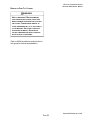
! WARNING!
Fluid escaping from a small hole can be
almost invisible. Use a piece of cardboard or
wood, rather than hands to search for suspected leaks.
! WARNING!
The arrangement of this hydraulic system
includes five separate circuits - boom lift,
boom extension, fork tilt, sway, and steering.
Fluid under pressure. Never attempt to
disconnect any hydraulic lines unless boom
and hydraulic operated components are
secured, without possibility of movement in
any direction. Relieve hydraulic system
pressure by working control levers. A circuit
may be completely depressurized by removing a pin from either rod end or base end of
cylinder(s). High pressure fluid and falling
components may cause injury or death.
The traversing machine hydraulic system
includes a separate circuit for the traversing
function.
The recommended hydraulic oil should have
antiwear, antifoam, antirust and antioxidation
properties for heavy duty use. The following
hydraulic oil viscosity is recommended for
use in this machine at all ambient temperatures.
! WARNING!
RECOMMENDED ASTM VISCOSITY:
ISO VG 32
Escaping fluid under pressure can have
sufficient force to penetrate the skin, causing
serious personal injury. Before disconnecting
lines, relieve all pressure. Before applying
pressure to the system, be sure all connections are tight and that lines, pipes and hoses
are not damaged.
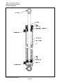
HYDRAULIC PRESSURE CHECKS AND ADJUSTMENTS
Occasionally, you should check the maximum
operating pressures in the hydraulic system.
There is no specified time interval as to when
these pressures should be checked. Usually,
pressure checks are made if the system is
unable to perform normal hydraulic functions.
The maximum operating pressure for the
hydraulic system is measured by operating
any hydraulic function to its maximum stroke
and holding it there while taking the gauge
reading. This causes the hydraulic pump to
provide maximum system pressure.
PETTIBONE/TRAVERSE LIFT, LLC
PAGE 6
FIXED AND TRAVERSING FORKLIFT
ADVANCED MAINTENANCE MANUAL
a. With engine off, attach a 600
psi gauge to the pilot pressure diagnostic check point.
Start engine and read gauge
value while actuating a
function.
b. On units equipped with Dana
axles/Clark transmission,
pilot pressure should be 500
psi + or 25 psi
c. On units equipped with
Carraro axles/transmission,
pilot pressure should be 300
psi + or 25 psi
NOTE: ALL PRESSURES SHOULD BE
TESTED WITH THE NORMAL OPERATING
TEMPERATURE OF THE HYDRAULIC OIL
FROM 80-120 °F (27-49 °C).
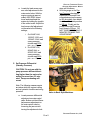
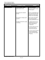
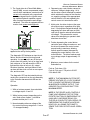
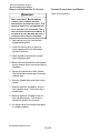
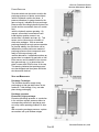
1. To check hydraulic pilot pressure:
a. Locate pilot pressure diagnostic point on machine.
2. To adjust pilot pressure:
a. Locate the brake manifold
block. Loosen jam nut on
pilot adjustment cartridge
and turn counter clockwise 2
full turns. Start the machine
and move the joystick function. Adjust pilot pressure to
the desired pressure above.
Tighten the jam nut and
operate functions to insure
correct pressure setting.
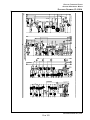
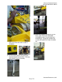
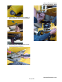
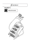
Pressure Checks, Valve in Front
Pressure Checks, Valve in Back
Brake manifold/Pilot adjust screw
PETTIBONE/TRAVERSE LIFT, LLC
PAGE 7
FIXED AND TRAVERSING FORKLIFT
ADVANCED MAINTENANCE MANUAL
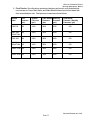
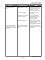
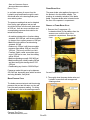
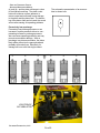
3. Set Pressure Compensator on
hydraulic pump:
a. Locate pressure compensator setting on the hydraulic
pump. With a 5000 psi
gauge on the System Pressure diagnostic point, retract
the boom and hold the function in the retract mode to
deadhead the system. Adjust
the pressure compensator on
the pump to 3450 psi + or
25 psi. This adjustment is
located on the lower quarter
of the pump on the side
closest to the operator compartment.
Locate the load sense relief adjustment on
the main valve and turn the adjustment
clockwise until it bottoms out. This sets the
main load sense relief at its maximum
setting.
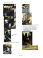
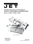
Pump Shaft End
Valve in Front Style Machines
Pressure Compensator adjustment
a. Once the pressure compensator has been set, the load
sense pressure relief on the
main control valve must be
adjusted
Valve in Back Style Machines
4. Set load sense pressure. The
initial conditions for this procedure
are with the engine running, and a
5000 psi gauge connected to the
load sense pressure test port.
PETTIBONE/TRAVERSE LIFT, LLC
PAGE 8
a. Locate the load sense pressure relief adjustment on the
main control valve. With the
engine running at approximately 2000 RPM, retract
boom and deadhead the
system by holding the joystick
in the retract mode. Adjust the
load sense relief adjustment
on the valve to the following
settings;
i. On 6044/F-644,
10056/F-1056, and
10044/F-1044, load
sense pressure
should read 3250
psi + or 25 psi.
ii. On 6036/F-636,
8044/F-844, or
8036/F-836, load
sense pressure
should read 2800
psi + or 25 psi.
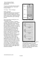
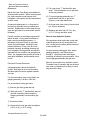
5. Set Pressure Differential
(Standby Pressure)
FIXED AND TRAVERSING FORKLIFT
ADVANCED MAINTENANCE MANUAL
wise until it bottoms.
b. With the gauge on the System Pressure check point,
Adjust the Differential Pressure adjustment on the pump
to 625 psi initially, then adjust
the Valve differential pressure
to 600 psi. Finally, set the
pump Differential Pressure
back down to 500 psi. DO
NOT TAKE MORE THAN 2-3
MINUTES TO MAKE THIS
ADJUSTMENT!
Valve in Front Style Machines
CAUTION! Do not run with the
pump pressure differential setting higher than the main valve
setting for more than 2-3 minutes! Pump overheating will
occur!
Note: The following measurements
are taken while the engine is idling
and no hydraulic functions are being
operated.
Valve in Back Style Machines
a. Locate pressure differential
adjustment on main control
valve. Bottom out the differential pressure adjustment on
the main control valve by
loosening the jam nut and
turning the adjustment clockPETTIBONE/TRAVERSE LIFT, LLC
PAGE 9
FIXED AND TRAVERSING FORKLIFT
ADVANCED MAINTENANCE MANUAL
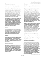
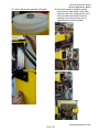
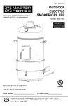
Differential Pressure Adjustment on Main
Control Valve
Pump Differential Pressure Adjustment
6. Set Steering Pressure: These
measurements must be taken with
the gauge on the Load Sense
diagnostic check point
a. Locate Steering Pressure
adjustment screw on the
brake manifold.
Steering Pressure Adjustment
PETTIBONE/TRAVERSE LIFT, LLC
PAGE 10
a. With the engine running,
bottom out steering by turning
wheels all the way in one
direction until it stops. Hold
wheel in this position
b. With gauge on the Load
Sense diagnostic point,
adjust the steering pressure
adjustment screw on the
brake manifold until steering
pressure is set to 2500 psi +
or 25 psi.
FIXED AND TRAVERSING FORKLIFT
ADVANCED MAINTENANCE MANUAL
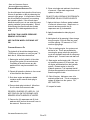
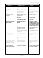
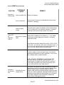
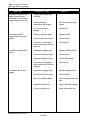
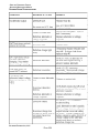
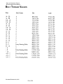
1. Final Checks: Once the above procedure has been performed, verify that all adjustment screws on Pump, Main Valve, and Brake Manifold have been locked down with
their associated jam nuts. Final pressure measurements as follows;
Machine
Model
Pilot
Pressure
(psi)
System
Pressure
(psi)
Load Sense Steering
Pressure
Pressure
(psi)
(psi)
Differential
Pressure (Standby
Pressure) (psi)
6036/F636
300
3450
2800
2500
500
6044/F-644
300
T-6044/T-644
3450
3250
2500
500
8036/F-836
300
3450
2800
2500
500
8044/F-844
T-8044/T-844 300
3450
2800
2500
500
10044/F-1044 300
3450
3250
2500
500
10056/F-1056 300
3450
3250
2500
500
PETTIBONE/TRAVERSE LIFT, LLC
PAGE 11
FIXED AND TRAVERSING FORKLIFT
ADVANCED MAINTENANCE MANUAL
CHECKING & ADDING HYDRAULIC OIL
You should inspect the hydraulic oil level every
8 hours of operation or daily by observing the
reservoir sight gauge. It is important to check
the oil level daily to prevent air from entering
the hydraulic system. If the oil level drops
below the suction port, air can enter the pump
causing cavitation (pump starvation). Return
fluid entering the reservoir will also contain
trapped air if it is discharged above the oil
level.
CAUTION! TANK UNDER PRESSURE.
REMOVE CAP SLOWLY.
6. Clean out sludge and sediment from bottom
of reservoir. Clean tank magnet and
replace on tank floor.
DO NOT FLUSH HYDRAULIC SYSTEM WITH
KEROSENE OR ANY OTHER SOLVENTS.
7. Apply a thin layer of silicone gasket sealant
to reservoir access cover. Install cover on
reservoir and secure with the (8)
capscrews and (8) lockwashers.
8. Apply thread sealant to drain plug and
install.
9. Add hydraulic oil by pumping it from storage
drum through a 10 micron filter into reservoir filler opening. Fill reservoir to FULL
mark on sight gauge.
USE CAUTION WHEN CHECKING HOT
OIL!
CHANGING HYDRAULIC OIL
The hydraulic oil should be changed every
1,000 hours of operation or once per year. To
drain the oil, follow these instructions:
1. Start engine and let hydraulic oil circulate
through the system for several minutes.
Circulating oil should remove any dirt
particles which may have settled in the
system.
2. Retract all hydraulic cylinders to force most
of the oil back to the reservoir.
10. Prior to starting engine, the system must
be bled of air. This is accomplished by
removing the pump outlet hose and pushing air into hydraulic tank until oil exits pump
pressure port. Connect hose and start unit.
11. Start engine and let engine idle. If there is
no hydraulic pressure in 30 seconds, turn
off engine and bleed air from the hydraulic
system. Restart engine to check for
hydraulic pressure. It is important that all
functions be operated to ensure that new oil
flows through all circuits.
3. Shut down engine and place a suitable
container under reservoir drain plug to
catch the oil.
12. Shut off engine. Add some more oil to
maintain proper level. This is necessary to
replace oil drawn into the system. DO
NOT OVER FILL.
4. Remove drain plug to drain oil. Allow time
for oil to drain from reservoir walls.
13. Inspect for leaks.
PROPERLY DISPOSE OF USED OIL. DO
NOT POUR OIL ON THE GROUND, INTO
SEWERS OR INTO BODIES OF WATER.
5. Remove the (8) capscrews and (8) lockwashers which secure the access cover to
the reservoir. Remove cover.
PETTIBONE/TRAVERSE LIFT, LLC
PAGE 12
FIXED AND TRAVERSING FORKLIFT
ADVANCED MAINTENANCE MANUAL
HYDRAULIC PUMP
HYDRAULIC OIL FILTERS
The hydraulic oil is filtered by a main return
line filters.
The main return line filters strain the oil returning to the reservoir from the main directional
valve.
The hydraulic system depends on these filters
to keep the oil clean. Filters which are not
cleaned or replaced at recommended intervals can become plugged with debris and lose
their ability to strain the oil.
Oil is circulated through the hydraulic system
by a variable volume piston pump located on
and driven by the torque converter. It contains
seven pistons that ride along a swash plate.
This swash plate, when adjusted, determines
the stroke of the pistons which in turn determines the amount of flow. The swash plate is
adjusted according to the amount of flow
required from the pump, which is determined
by the load on the hydraulics.
After the first 40 hours of operation, filters
should be replaced. This is necessary since
the oil may contain a high concentration of
metal particles from initial wear of the new
valves and cylinders. Refer to the owners
service guide to determine when the filters
should be replaced.
IN-TANK RETURN FILTERS
After the first 50 hours of operation, filters
should be replaced. Refer to the owners
service guide to determine when the filters
should be replaced.
HYDRAULIC PUMP LINES
PETTIBONE/TRAVERSE LIFT, LLC
PAGE 13
FIXED AND TRAVERSING FORKLIFT
ADVANCED MAINTENANCE MANUAL
PUMP CAVITATION
1. Thoroughly clean the pump and hydraulic
connections with a cleaning solvent.
Cavitation occurs when an insufficient supply
of oil reaches the pump suction chamber.
Since the pump does not receive enough oil, it
begins sucking in air instead. This condition is
indicated by a high noise level in the pump.
IF THE PUMP EMITS A HIGH-PITCHED
NOISE, SHUT OFF ENGINE IMMEDIATELY.
CONTINUED OPERATION OF A CAVITATING
PUMP WILL CAUSE SEVERE DAMAGE TO
ITS WORKING PARTS.
To prevent cavitation:
1. Keep hydraulic oil level up to FULL mark
on reservoir dipstick.
2. Allow oil to warm up in cold weather.
3. Keep suction line free of obstructions.
REMOVAL OF PUMP
Should you find it necessary to service
the hydraulic pump during its life expectancy,
you will see a noticeable drop in performance
occur. It is advisable to make an inspection
and replace parts or components which may
have become worn. Expendable parts such
as o-rings, seals, washers and gaskets
should never be reused even though inspection may show these items as being serviceable. Alternately, the complete unit may be
replaced.
2. Match-mark the hydraulic lines and pump
ports to ensure correct connections during
installation.
3. Disconnect hydraulic lines from pump. Cap
the lines and pump ports to prevent contamination.
4. Attach a suitable lifting strap from hoist to
pump.
5. Remove the (2) capscrews and (2) lockwashers which secure the pump to the
torque converter. Lift pump from machine.
PUMP SERVICE INFORMATION
For complete pump service information, refer
to the service guide included at the end of this
manual.
INSTALLATION OF PUMP
! WARNING
Heavy components! Before installing
the pump, check its weight and make
provisions for attaching and lifting.
Use a hoist capable of supporting the
weight. A slipping or falling component may result in injury or death to
personnel.
! WARNING!
Heavy components! Before removing
the pump, check its weight and make
provisions for attaching and lifting.
Use a hoist capable of supporting the
weight. A slipping or falling component may result in injury or death to
personnel.
1. Secure a suitable lifting strap from hoist
to pump. Lift the pump into position on
torque converter.
2. Install a new gasket between the torque
converter and the pump. Hold the gasket in
place with a light coating of grease.
PETTIBONE/TRAVERSE LIFT, LLC
PAGE 14
3. Insert pump driveshaft into torque converter
drive, being certain to properly engage
splines. Secure pump to converter with the
(2) capscrews and (2) lockwashers.
Remove lifting strap.
FIXED AND TRAVERSING FORKLIFT
ADVANCED MAINTENANCE MANUAL
4. Fill pump ports with clean hydraulic oil to
provide initial lubrication.
5. Connect hydraulic lines to pump and bleed
air from system.
6. Start engine. Prime the pump by letting the
engine idle with no load applied to the
hydraulic system for at least two minutes.
Inspect pump for leaks.
HYDRAULIC PUMP TROUBLESHOOTING CHART AND
SERVICE REPAIR
The following chart lists the common difficulties experienced with the hydraulic pumps. It
also indicates the probable causes and
remedies for each of the troubles listed. This
chart is organized to cover trouble that may
occur due to improper service and maintenance. It should always be remembered that
many apparent pump failures are actually the
failures of other parts of the systems. The
causes of improper operation are best diagnosed with adequate testing equipment and a
thorough understanding of the complete
hydraulic system.
Please refer to your Parts Manual for pump
parts breakdown.
PETTIBONE/TRAVERSE LIFT, LLC
PAGE 15
FIXED AND TRAVERSING FORKLIFT
ADVANCED MAINTENANCE MANUAL
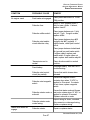
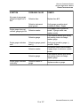
HYDRAULIC PUMP TROUBLESHOOTING
SYMPTOM
Pump not delivering oil
PROBABLE CAUSE
REMEDY
Pump driveshaft coupling
sheared (direct drive).
Remove pump and
determine damage. Replace
defective parts.
Oil suction port in reservoir
blocked.
Remove contamination and
flush suction line with clean
hydraulic oil. Check sump
strainer for dirt and sludge.
Oil viscosity too heavy to pick
up prime.
Drain system and replace
with new oil of correct
viscosity (ASTM ISO VG 32).
Air leaks on suction line, pump
not priming.
(1) Inspect suction line for
leaks by pouring oil over
fittings. Tighten loose
connections.
(2) Check reservoir oil level.
The oil level must be
above the suction port.
(3) Check minimum speed of
pump driveshaft which
may be too slow to prime
the pump.
PETTIBONE/TRAVERSE LIFT, LLC
PAGE 16
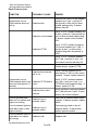
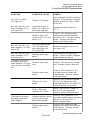
HYDRAULIC PUMP TROUBLESHOOTING
SYMPTOM
Pump makes excessive
noise
Pump never stops pumping,
oil is excessively hot, or main
directional valve makes excessive noise.
PROBABLE CAUSE
FIXED AND TRAVERSING FORKLIFT
ADVANCED MAINTENANCE MANUAL
REMEDY
Partially blocked suction line.
Remove contamination and
flush suction line with clean
hydraulic oil. Check for
loose lining in suction hose.
Low oil level in reservoir.
Add oil to FULL mark on
sight gauge.
Air leak at pump suction hose
joint or pump shaft seal.
Pour oil over fittings and
around driveshaft to check
for air leaks. Replace
defective pump seal.
Collapsed suction hose.
Test at full rpm as hose may
be normal at low speed, but
collapses at high
speed.Replace as necessary.
Improper DP setting between
pump and main directional
valve
Adjust DP pressure setting
using the pressure adjustment
procedures.
PETTIBONE/TRAVERSE LIFT, LLC
PAGE 17
FIXED AND TRAVERSING FORKLIFT
ADVANCED MAINTENANCE MANUAL
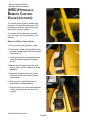
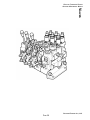
REMOTE-CONTROLLED
MAIN DIRECTIONAL
VALVE
All of the boom functions are pilot controlled at
the main directional valve.
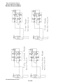
This machine is equipped with an L90LS
closed-center proportional load sensing and
pressure compensated system valve.
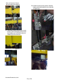
Oil from the pump enters the directional valve
through the inlet port located on the far left
section, as shown. Oil returns to the reservoir
through the outlet port located on the section
that is on the opposite side of the valve, as
shown, also.
REAR OF MACHINE
MAIN DIRECTIONAL VALVE - NO PLUMBING
MAIN DIRECTIONAL VALVE - INSTALLED
FRONT OF MACHINE
PETTIBONE/TRAVERSE LIFT, LLC
PAGE 18
FIXED AND TRAVERSING FORKLIFT
ADVANCED MAINTENANCE MANUAL
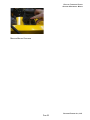
The LS, PX, PL, and LSP functions are shown
below:
LS -
This is the Load Sense Pressure line
that sends the load signal back to the
hydraulic pump.
PX -
This line sends oil to the system
pressure test port
PL -
This line sends oil to the load sense
pressure test port.
LSP - This line carries load sense pressure
returning from the brake/steering
systems.
P2B - This line sends oil to the brake charge
manifold.
P2B
PETTIBONE/TRAVERSE LIFT, LLC
PAGE 19
FIXED AND TRAVERSING FORKLIFT
ADVANCED MAINTENANCE MANUAL
REMOVAL OF MAIN VALVE
INSTALLATION OF MAIN VALVE
! WARNING!
1. Install the valve onto the mount and secure
with the (4) capscrews, (4) lockwashers
and (4) nuts. Remove lifting strap.
Heavy components! Before removing
the valve, check its weight and make
provisions for attaching and lifting.
Use a hoist capable of supporting the
weight. A slipping or falling component may result in injury or death to
personnel.
2. Connect hydraulic lines, electrical plugs
and solenoids to valve.
3. Connect ground cable to battery.
1. Disconnect battery ground cable.
4. Start engine and actuate all valve functions
to ensure correct operation. Inspect valve
for leaks.
2. Remove the access cover.
5. Install access cover.
3. Thoroughly clean the valve and hydraulic
connections with a cleaning solvent.
4. Match-mark hydraulic lines and valve ports
to ensure correct connections during
installation.
5. Disconnect all hydraulic lines from the
valve bank and ensure that there is a
container to catch any oil that will spill. Cap
the lines and valve ports to prevent contamination.
6. Match-mark the electrical plugs and solenoids to ensure correct connections during
installation.
7. Secure a suitable lifting strap from hoist to
valve.
8. Remove the (4) capscrews, (4)
lockwashers and (4) nuts which secure the
valve to the mount. Lift valve from machine.
PETTIBONE/TRAVERSE LIFT, LLC
PAGE 20
FIXED AND TRAVERSING FORKLIFT
ADVANCED MAINTENANCE MANUAL
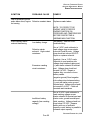
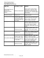
MAIN DIRECTIONAL VALVE TROUBLESHOOTING
SYMPTOM
PROBABLE CAUSE
REMEDY
Oil leaks at either end of
spool
Defective o-ring(s) in spool
control.
Replace o-ring(s).
Oil leaks between
sections
Pinched or blown seal(s).
Replace seal(s).
Tie rod fasteners not
correctly torqued.
Torque fasteners to 44 ft.
lbs.(60 Nm).
Spool does not return to
neutral position
Broken centering spring(s)
in spool control.
Replace spring(s).
Bent spool.
Replace section.
Foreign particles in valve.
Clean valve.
Defective fuse, switch or
solenoid.
Ensure that 12 vdc is
available to solenoid coil. If
no voltage available, replace
fuse or switch. If voltage is
available, replace solenoid.
Defective electrical wire
from switch to solenoid.
Repair wiring defects or
replace wiring.
Electrical plug disconnected
from solenoid.
Connect plug to solenoid.
Low oil level in reservoir.
Add oil to FULL mark on
sight gauge.
Valve body cracked inside.
Replace valve section.
Spool not moved to full
stroke.
Check spool travel.
Main valve makes excessive
noise, oil excessively hot, or
pump does not stop pumping
Improper DP setting between pump and valve.
Adjust accroding to procedure of main valve and
pump.
Load drops when spool
moved to a working position
Load larger than capacity.
Reduce to rated load capacity at rated load center.
Solenoid for fork frame side
tilt fails to energize
No motion, slow or jerky
action of hydraulic system
PETTIBONE/TRAVERSE LIFT, LLC
PAGE 21
FIXED AND TRAVERSING FORKLIFT
ADVANCED MAINTENANCE MANUAL
(HRC) HYDRAULIC
REMOTE CONTROL
VALVE (JOYSTICK)
The remote control (joystick) valves supply
pressure to the main directional valve. This
pilot pressure shifts the main valve spools
which direct oil to the cylinders.
The remote control valves are mounted in
front of the arm rest, in the operators compartment.
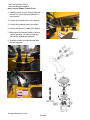
REMOVAL OF REMOTE CONTROL VALVES
JOYSTICK S
1. Disconnect the battery ground (-) cable.
2. Remove the console cover by taking off the
two wing nuts that hold on the arm rest and
lift the cover off.
3. Thoroughly clean the valves and hydraulic
connections with an approved cleaning
solvent.
4. Match-mark the hydraulic lines and valve
ports to ensure correct connections during
installation.
5. Disconnect hydraulic lines from joystick.
Cap the lines and valve ports to prevent
contamination.
6. Disconnect the joystick electrical wire
underneath the mounting bracket.
7. Remove the four (4) socket head fasteners
on each of the joysticks, and remove the
joysticks.
PETTIBONE/TRAVERSE LIFT, LLC
PAGE 22
FIXED AND TRAVERSING FORKLIFT
ADVANCED MAINTENANCE MANUAL
MOUNTING BRACKET CAPSCREWS
PETTIBONE/TRAVERSE LIFT, LLC
PAGE 23
FIXED AND TRAVERSING FORKLIFT
ADVANCED MAINTENANCE MANUAL
INSTALLATION OF REMOTE CONTROL VALVE
1. Install the valves onto the mounting bracket
with the four (4) socket head fasteners for
each joystick.
2. Connect the joystick wires to the terminal.
3. Connect the hydraulic lines to the valves.
4. Connect the ground (-) cable to the battery.
5. Start engine and actuate joystick to ensure
correct operation. Be sure to check forl
eaks as the joysticks are operated.
6. Replace console cover and armrest with
the two wing nuts.
PETTIBONE/TRAVERSE LIFT, LLC
PAGE 24
FIXED AND TRAVERSING FORKLIFT
ADVANCED MAINTENANCE MANUAL
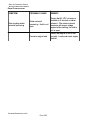
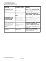
REMOTE CONTROL (JOYSTICK) TROUBLESHOOTING
SYMPTOM
PROBABLE CAUSE
REMEDY
Improper stand-by pressure.
Adjust the pressure compensator.
Not enough pilot pressure
supplied to main valve.
Pilot pressure should be
within the range of 300 psi
(±25 psi). If it is not, clean
filter and clean or replace
pilot spool.
Leak(s) in pilot lines from
remote control valve.
Tighten pilot hose couplings
or replace defective hoses.
Blocked pilot lines.
Remove contamination and
flush pilot lines with clean
hydraulic oil.
Joystick chatters
Pilot pressure too high.
Check pilot pressure using
a 600 psi pressure gauge.
Correct pressure should be
within the range of 300 psi
(±25 psi). If pressure is too
high, clean or replace pilot
spool in main directional
valve.
Wrong response to
joystick movement
Pilot lines connected to
wrong valve ports.
Reconnect lines to correct
ports.
Joystick does not center
Broken centering springs.
Replace springs.
0il leaks between sections
of remote control valve
Defective section o-ring.
Replace o-ring.
Pilot-operated spools in
main valve do not shift
when joystick is actuated
PETTIBONE/TRAVERSE LIFT, LLC
PAGE 25
FIXED AND TRAVERSING FORKLIFT
ADVANCED MAINTENANCE MANUAL
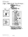
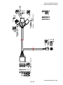
FORK TILT AND AUXILIARY HYDRAULIC JOYSTICK
WITH 2 AXIS DRIVE CARD
Overview
The Fork Control; Consist of four control
buttons mounted in the joystick handle, the 2
axis driver module, the solenoid operated forkup down section of the main valve, the auxiliary fork rotate solenoid operated valve, the
auxiliary charge relay and the charge solenoid
valve on the brake charge manifold.
Proportional D1VW Solenoid Valve
L90 Tilt Section Solenoids
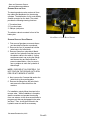
1. The fork up and down buttons supply an
analog voltage reference to the 2 axis
driver proportional to button depression,
varying approximately .5 VDC to 4.2 VDC,
to control the speed of operation.
Digital PWM Module
2.The 2 Axis driver is located under the armrest bracket, underneath the fiberglass
console on the RH side of the operator
compartment.
Fork Tilt and Auxiliary Function Joystick with
Digital PWM Module
PETTIBONE/TRAVERSE LIFT, LLC
PAGE 26
3. The 2 axis driver is a Pulse Width Modulated (PWM), current compensated output
control which maintains a constant level of
current to the solenoid coils, proportional
to an input signal from the joystick ensuring constant hydraulic operation regardless of system temperature and voltage
variations. The driver is equipped with two
monitor Leds; power and diagnostic.
',$*
32:(5
/('
/('
3,1
3,1
The power LED lights whenever power is
applied to the unit by the key switch.
The diagnostic LED indicates an input circuit
failure, and should not be lit during normal
operation. An open circuit in any of the input
circuits from the joystick, fork up or down and
fork rotate cw or ccw will cause the LED to
light and the driver to lock out ALL output
functions; therefore, and input failure in forkup-down will also lock out fork cw-ccw operation, and vice versa.
The diagnostic LED can be tested by disconnecting the connector from the grip assembly
to the controller harness which will turn the
LED on.
FIXED AND TRAVERSING FORKLIFT
ADVANCED MAINTENANCE MANUAL
4. Depressing any control button causes its
reference voltage to begin rising. At l.4
vdc the driver control threshold is reached,
which switches the output of that function
on, supplying voltage to the appropriated
control solenoid coil, and regulating the
control current to it at minimum value.
5. At this point, the driver locks out the opposite motion output, regardless of its input
level. If fork up has reached threshold, fully
depressing fork down will have no effect
until fork up input is reduced below threshold voltage. This prevents the control
valves from attempting to operate in both
directions at one time.
6. Further depressing the control button
varies the input voltage to maximum, and
the driver increases the control current
proportionally to maximum, allowing
smooth speed increase (decrease by
releasing the control button) of the controlled function. The driver reaches maximum voltage output of approximately 3.6
VDC.
7. Maximum current values for the control
Solenoids Are;
Fork up, Fork down 1.0A
Fork cw, Fork ccw 1.75A prior to 8/1/00
2.0 A after 8/1/00
NOTE 1: THAT MAXIMUM JOYSTICK REFERENCE VOLTAGE OF 4.2 VDC IS ABOVE
THE 3.6 V INPUT NECESSARY FOR MAXIMUM DRIVER CURRENT OUTPUT. THIS
ASSURES FULL SOLENOID SHIFT FOR
MAXIMUM SPEED.
Operation
1. With no buttons pressed, there should be
no voltage at pins 11 and 12.
2. With a button pressed, depending on the
axis, Vbatt minus of about 1 volt will be
present at either pin 11 or 12.
3. Normal standby reference voltage of the
four control input may range from .5 vdc to
1.2 vdc approximately.
NOTE 2: THE DRIVER ALSO CONTROLS
PUMP LOAD SENSING FOR THE FORK
ROTATE FUNCTION, BY ENERGIZING THE
AUXILIARY LOAD SENSE RELAY COIL.
THE RELAY CONTACTS THEN OPENS, DEENERGIZING THE CHARGE VALVE SOLENOID COIL, ALLOWING THE PUMP TO
SENSE THE FORK ROTATE VALVE OPERATION.
PETTIBONE/TRAVERSE LIFT, LLC
PAGE 27
FIXED AND TRAVERSING FORKLIFT
ADVANCED MAINTENANCE MANUAL
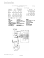
63(&,),&$7,216
.%<7(62),1&,5&8,7352*5$00$%/()/$6+
,13876$1$/2*9'&
2873876$03&855(17&203(16$7('3523257,21$/
$03212))
$;,6'5,9(5
32:(5,13879'&
7(03&72&
&211(&725$036($/3/8*
$036($/62&.(73,1
32:(5
/('
(19,5210(17$/5$7,1*72$0363(&
:+,&+,6$1,3(48,9$/(17
PETTIBONE/TRAVERSE LIFT, LLC
PAGE 28
FIXED AND TRAVERSING FORKLIFT
ADVANCED MAINTENANCE MANUAL
PETTIBONE/TRAVERSE LIFT, LLC
PAGE 29
FIXED AND TRAVERSING FORKLIFT
ADVANCED MAINTENANCE MANUAL
JOYSTICK SCHEMATIC SYMBOL
PETTIBONE/TRAVERSE LIFT, LLC
PAGE 30
FIXED AND TRAVERSING FORKLIFT
ADVANCED MAINTENANCE MANUAL
JOYSTICK-PWM TROUBLESHOOTING
6<03720
1RSRZHUWR
3:00RGXOH
3RZHU/('
RQ
'LDJQRVWLF
/('RQ
352%$%/(
&$86(
5(0('<
&KHFNIXVH)$ 5HSODFHLIQHFHVVDU\
/RRVHFRQQHFWLRQV
&KHFNKDUQHVVIRUORRVHRUPLVDOLJQHGSLQVWRGULYHUERDUG
FRQQHFWLRQZD\SOXJ
,QFRUUHFWV\VWHP
YROWDJH
9HULI\WKDWV\VWHPYROWDJHLVDYDLODEOHWRGULYHUERDUGEHWZHHQ
SLQDQGSLQRQWKHGULYHUFRQQHFWRU,IYROWDJHLV
SUHVHQWDQG/('GRHVQRWOLJKWUHSODFHGULYHUERDUG
9HULI\9'&WRMR\VWLFNSLQDQGSLQ,IQRYROWDJH
2SHQFLUFXLWLQMR\VWLFN
FKHFNGULYHUWRMR\VWLFNKDUQHVVIRUFRQWLQXLW\,IFRQWLQXLW\
LQSXWV
UHSODFHGULYHUFDUG
9HULI\VWDQGE\UHIHUHQFHYROWDJHIURPMR\VWLFN9'&9'&
SLQWRSLQSLQWRSLQSLQWRSLQDQGSLQWRSLQ,I
RQHRUPRUHQRWSUHVHQWFKHFNSOXJIRUEDGRUEURNHQSLQV,I
QRSLQVDUHEDGUHSODFHMR\VWLFNRUMR\VWLFNVZLWFK
,IVWDQGE\YROWDJHLVSUHVHQWDWMR\VWLFNSOXJFKHFNKDUQHVV
FRQWLQXLW\DWSOXJDQGGULYHURQDOOLQSXWZLUHV,IRQHRUPRUH
IDLOVFRQWLQXLW\UHSDLURUUHSODFHKDUQHVV
127(67$1'%<5()(5(1&(92/7$*(0867%(
35(6(1721$//'5,9(5&21752/,1387672
&$1&(/,1387)$,/85(/('$1'287387/2&.287
)81&7,21(9(1:+(181,7,6127(48,33(':,7+
$8;)25.527$7(9$/9($1'&,5&8,7
2SHUDWHVLQ
RQHGLUHFWLRQ
RQO\
7KUHVKROGPLQLPXP
YROWDJHORFNRXW
,IWKHLQSXWRIRQHGLUHFWLRQDOFRQWUROEXWWRQVWDQGE\YROWDJHLV
VOLJKWO\DERYH9'&EXWQRWKLJKHQRXJKWRDOORZWKHGULYHU
ERDUGWRVXSSO\PLQLPXPFXUUHQWQHFHVVDU\WRVKLIWWKH
K\GUDXOLFYDOYHFRQWUROVSRROWKHUHE\ORFNLQJLWVRSSRVLWHEXWWRQ
FRQWURORXW,IWKLVLVVXVSHFWHGVZLWFKLQJWKHLQSXWZLUHVRIWKH
DIIHFWHGFLUFXLWZLOOFDXVHWKHORFNRXWVZLWFKLHXSWRGRZQRU
OHIWWRULJKWWRRSSRVLWHRIWKHRULJLQDOIDXOW5HSODFHWKH
MR\VWLFNEXWWRQLIWKDWDSSHDUVWRZRUN
PETTIBONE/TRAVERSE LIFT, LLC
PAGE 31
FIXED AND TRAVERSING FORKLIFT
ADVANCED MAINTENANCE MANUAL
JOYSTICK-PWM TROUBLESHOOTING
6<03720
2SHUDWHVLQ
RQHGLUHFWLRQ
RQO\
1RRXWSXW
IXQFWLRQV
6OXJJLVKRU
VORZ
RSHUDWLRQRI
IRUNURWDWH
352%$%/(
&$86(
5(0('<
,QFRUUHFWSLORW
SUHVVXUHRUEDG
VROHQRLG
9HULI\K\GUDXOLFVROHQRLGYDOYHRSHUDWLRQE\VZLWFKLQJSOXJVRQ
WKHYDOYHDQGGHSUHVVLQJFRQWUROEXWWRQV,IFRQWUROVZLWFKHV
GLUHFWLRQUHSODFHVROHQRLGFRLODQGRUFKHFNK\GUDXOLFSLORW
SUHVVXUH9HULI\VROHQRLGFRLOFRQWLQXLW\DQGUHVLVWDQFHZLWK
RKPPHWHU3URSHUFRLOUHVLVWDQFHDW)LVDSSUR[RKP
IRUPDLQYDOYH/FRLOVDQGRKPIRUDX[VROHQRLG
YDOYH'9:FRLOV127(&2,/5(6,67$1&(:,//9$5<
:,7+7(03(5$785(9$5,$7,21
%DGFRQWLQXLW\RU
GULYHUERDUG
9HULI\OLQHYROWDJHSUHVHQWDWSLQ'PHDVXUHGWRJURXQG
)UDPHRQ3DFNDUGSLQRXWSXWSOXJZKHQFRQWUROEXWWRQLV
GHSUHVVHG,IQRWSUHVHQWYHULI\FRQWLQXLW\RIKDUQHVVEHWZHHQ
SLQ'DQGSLQRIWKHSLQDPSSOXJIRUIRUNXSGRZQ)RU
IRUNURWDWHOHIWULJKWYHULI\FRQWLQXLW\EHWZHQSLQ'DQGSLQRI
WKHSLQDPSSOXJ,IFRQWLQXLW\LVJRRGUHSODFHGULYHUERDUG
%DGGULYHUERDUGRU
DX[ORDGVHQVHUHOD\
7RYHULI\SXPSORDGVHQVHRSHUDWLRQPHDVXUHOLQHYROWDJH
SUHVHQWRQSLQ%RI3DFNDUGSRVLWLRQSOXJZKHQIRUNURWDWH
EXWWRQHLWKHULVGHSUHVVHG,IQRWSUHVHQWYHULI\KDUQHVV
FRQWLQXLW\EHWZHHQSLQ&DQGSLQRIWKHSLQDPS
FRQQHFWRU,IFRQWLQXLW\LVJRRGUHSODFHGULYHUERDUG,IYROWDJH
LVSUHVHQWYHULI\DX[ORDGVHQVHUHOD\RSHUDWLRQE\FKHFNLQJ
WKDWYROWDJHLVUHPRYHGIURPFKDUJHYDOYHVROHQRLGFRLOSLQ$WR
JURXQGZKHQHLWKHUIRUNURWDWHEXWWRQLVGHSUHVVHG,IYROWDJH
UHPDLQVFRQVWDQWUHSODFHDX[ORDGVHQVHUHOD\
6OXJJLVKRU
VORZ
RSHUDWLRQRI
)RUN7LOW
7RYHULI\DFWXDOIXOOVWURNHRSHUDWLRQRIWKHYDOYHFRQWURO
VROHQRLGVLQVHUWDQDPPHWHULQOLQHZLWKSLQ'RQERWKRXWSXW
SRVLWLRQFRQQHFWRUVSRVWRZDUGGULYHUERDUGQHJWRZDUG
YDOYH)XOOVWURNHFXUUHQWUHDGLQJVREWDLQHGZLWKEXWWRQIXOO\
GHSUHVVHGDUH)RUN8S$)RUN'RZQ$)RUN&:
$)RUN&&:$6HHQRWHDQGEHORZ
127()8//6752.(&855(175($',1*2)$8;
)25.527$7(:,//&+$1*()520D72D
72$&&202'$7()8//)/2:72$8;)81&7,21
127(%(&$86(7+('5,9(523(5$7,21,6&855(17
&203(16$7('92/7$*(5($',1*67$.(1$&5266
7+(23(5$725&2,/6:,//9$5<:,7+7(03(5$785(
$1'$5(7+(5()25(127$1$&&85$7(,1',&$7252)
'5,9(53(5)250$1&(
127(7(67/,*+76$5(1275(&200(1'('6,1&(
7+(/,*+7:,//',9(57$6,*1,),&$173257,212)7+(
'5,9(5287387&855(17$1':,//$/7(59$/9(
3(5)250$1&(
PETTIBONE/TRAVERSE LIFT, LLC
PAGE 32
FIXED AND TRAVERSING FORKLIFT
ADVANCED MAINTENANCE MANUAL
STEERING ORBITROL
PETTIBONE/TRAVERSE LIFT, LLC
PAGE 33
FIXED AND TRAVERSING FORKLIFT
ADVANCED MAINTENANCE MANUAL
2. Then remove the horn cover, horn wire,
steering wheel and horn button cover and
button from the steering column.
The steering orbitrol supplies oil pressure to
the steering selector valve for distribution to
the steering cylinders. The pressure is created by rotation of the steering wheel. The
orbitrol is mounted under the instrument
panel.
ORBITROL REMOVAL
1. First remove the push screws from both
sides of the dash by popping out with a
pen light or small screwdriver. These
can be reused.
Cover
Horn Wire
Left Side
Steering Wheel
Right Side
Horn Button Cover
PETTIBONE/TRAVERSE LIFT, LLC
PAGE 34
FIXED AND TRAVERSING FORKLIFT
ADVANCED MAINTENANCE MANUAL
4. Now remove the left hand panel from the
dash and disconnect all wire connections.
Horn Button
Left side dash panel
3. Remove the shifter assembly from the
column by removing the 2 allen head bolts.
NOTE: WHEN REINSTALLING TAKE CARE
NOT TO OVERTIGHTEN. OVERTIGHTENING CAN STRESS THE PLASTIC AND IT
COULD BREAK. SEE TORQUE SPECS.
Parking brake and clutch cut-off connection
Shifter Assembly
Left side panel wiring harness connections
PETTIBONE/TRAVERSE LIFT, LLC
PAGE 35
FIXED AND TRAVERSING FORKLIFT
ADVANCED MAINTENANCE MANUAL
5. Remove the right side panel cover and all
connections next.
Right panel with optional lighting switches.
Right panel connections.
6. Remove key switch nut and cover from
dash.
Dash cover with removed panels
7. Remove the lower dash panel by removing the knob and all 6 screws.
Lower dash panel.
Lower dash panel knob.
Key switch nut.
PETTIBONE/TRAVERSE LIFT, LLC
PAGE 36
FIXED AND TRAVERSING FORKLIFT
ADVANCED MAINTENANCE MANUAL
9. Disconnect hoses and cap ports to prevent
contamination.
Dash panel screw.
10. Remove the four bolts with lockwashers
from the frame. NOTE: If you need to
replace the bolts that were removed at this
point, do not use bolts longer than 5/8.
Longer bolts will damage the orbitrol.
Removing the panel
8. Unwrap wires from left side off of steering
column to make access to column easier.
11. Loosen clamp assembly on upper cover
of steering column and remove from
machine.
PETTIBONE/TRAVERSE LIFT, LLC
PAGE 37
FIXED AND TRAVERSING FORKLIFT
ADVANCED MAINTENANCE MANUAL
REASSEMBLY
HORN BUTTON.
For installation, simply follow the steps in the
reverse order. When installation is complete,
start the machine and operate the steering
from one extreme to the other several times to
purge any air that may be trapped in the valve
and lines. Then, check the fluid level in the
hydraulic reservoir.
1. Remove the horn cover, horn wire, steering
wheel and horn button cover and button
from the steering column. You will also
need to unbolt the clamp from the upper
column to remove the wire. Use proper
torque specifications when reassembling.
TORQUE SPECIFICATIONS
Clamp = 20 foot/pounds
Steering Wheel Nut = 32-37 foot/pounds
Shifter Assy Bolts = 18 inch/pounds
PETTIBONE/TRAVERSE LIFT, LLC
PAGE 38
FIXED AND TRAVERSING FORKLIFT
ADVANCED MAINTENANCE MANUAL
VALVES
PETTIBONE/TRAVERSE LIFT, LLC
PAGE 39
FIXED AND TRAVERSING FORKLIFT
ADVANCED MAINTENANCE MANUAL
STEERING SELECTOR VALVE
The steering selector valve receives oil from
the orbitrol and distributes it to the steering
cylinders. The distribution of oil is controlled by
a switch mounted on the dash. The switch
provides the following steering functions:
1. Two-wheel steer
2. Four-wheel steer
3. Oblique (crab) steer
The selector valve is mounted in front of the
battery box.
VALVE BODY TO VALVE BLOCK SCREWS
STEERING SELECTOR VALVE REMOVAL
1. First remove figerglass cover and disconnect electrical connection on solenoid.
2. Remove the four (4) screws that hold the
valve body to the valve block.
3. Remove hoses from valve block. Match
mark the four hydraulic lines that connect
the selector valve to the orbitrol. As they
are disconnected, cap or plug the fittings
and lines as they are disconnected to
prevent contamination. Also, be sure to
use a container to catch the hydraulic oil
that will spill.
NOTE: DISPOSE OF OIL PROPERLY. DO
NOT POUR ON THE GROUND, INTO SEWERS OR INTO BODIES OF WATER.
4. Next, remove the 2 screws that anchor the
valve block to the mounting plate.
5. Remove the fittings from the valve block
and remove the valve block from the
machine.
For installation, simply follow the steps in the
reverse order. When installation is complete,
start the machine and operate the steering
from one extreme to the other several times to
purge any air that may be trapped in the valve
and lines. Then, check the fluid level in the
hydraulic reservoir and fill as necessary.
PETTIBONE/TRAVERSE LIFT, LLC
PAGE 40
FIXED AND TRAVERSING FORKLIFT
ADVANCED MAINTENANCE MANUAL
STEERING SELECTOR TROUBLESHOOTING
6<03720
352%$%/(&$86(
5(0('<
6WHHULQJKDVZKHHO
VWHHURQO\
'HIHFWLYHIXVH
9HULI\9'&SUHVHQWWRVWHHU
VZLWFKRQJU\UHGOHDG,ISUHVHQW
UHSODFHIXVH
'HIHFWLYHVZLWFK
9HULI\9'&SUHVHQWEHWZHHQSLQ
RUJDQGSLQEONRQ
VROHQRLG%SOXJRIVWHHULQJYDOYH,I
DEVHQWUHSODFHVZLWFK
1RZKHHOVWHHU
9HULI\9'&SUHVHQWEHWZHHQSLQ
EOXDQGSLQEONRI
VROHQRLG$SOXJRIVWHHULQJYDOYH,I
DEVHQWUHSODFHVZLWFK
1RFUDEVWHHU
'HIHFWLYHVROHQRLGFRLO
9HULI\UHVLVWDQFHRIDIIHFWHGFRLORI
RKPV,IRSHQRUKLJKUHSODFH
FRLORUYDOYH
'HIHFWLYHYDOYH
,IHOHFWULFFKHFNRNUHSODFHYDOYH
PETTIBONE/TRAVERSE LIFT, LLC
PAGE 41
FIXED AND TRAVERSING FORKLIFT
ADVANCED MAINTENANCE MANUAL
NOTES
PETTIBONE/TRAVERSE LIFT, LLC
PAGE 42
FIXED AND TRAVERSING FORKLIFT
ADVANCED MAINTENANCE MANUAL
CYLINDERS
PETTIBONE/TRAVERSE LIFT, LLC
PAGE 43
FIXED AND TRAVERSING FORKLIFT
ADVANCED MAINTENANCE MANUAL
All hydraulic cylinders on this machine are
double-acting. Oil entering the base end port
of the cylinder extends the rod. Oil entering
the rod end port retracts the rod.
5. Remove cotter pin from piston lock nut.
Unfasten lock nut. Slide piston, spacer
and head from rod.
DISASSEMBLY OF CYLINDER (GENERIC)
1. Place a suitable container below the
cylinder to catch the oil when the rod
assembly is pulled out.
COTTER PIN
6. Remove all software from head and
piston. Discard software.
7. Wash all metal parts in an approved
cleaning solvent and dry thoroughly with a
clean, lint-free cloth.
8. Inspect barrel, rod and piston for nicks,
scratches and scoring.
9. Replace any damaged parts and seals as
necessary.
ASSEMBLY OF CYLINDER (GENERIC)
2. Remove set screw from collar.
1. Coat new software with clean hydraulic oil.
3. Using a strap or chain wrench, unscrew
the collar.
4. Use a suitable puller to remove the piston
rod assembly from the barrel.
2. Install head o-ring and head back-up ring in
groove on outside diameter of head. Oring must be closest to small end of head.
3. Install head wear ring in large groove on
inside diameter of head.
PETTIBONE/TRAVERSE LIFT, LLC
PAGE 44
FIXED AND TRAVERSING FORKLIFT
ADVANCED MAINTENANCE MANUAL
9. Carefully slide collar on rod, then the head.
Use caution to prevent cutting the wiper on
the rod.
LARGE END
4. Install rod seal and modular back-up ring in
second largest groove inside head. Lips
of rod seal must face small end of head.
Modular back-up ring must be closest to
large end of head.
5. Install rod wiper in groove on large end of
head with wiper lips facing large end.
10. Slide spacer on rod, then the piston.
11. Fasten piston lock nut on end of rod.
Insert new cotter pin through nut.
12. Insert piston rod assembly into cylinder
barrel. Lubricate threads with anti-seize
before installing collar.
6. Install piston seal in center groove on
outside diameter of piston.
7. Install the piston wear rings (2) in remaining grooves on outside diameter of piston.
SEAL
13. Fasten collar on barrel with strap or chain
wrench.
WEAR RINGS
8. Install stub o-ring in groove on inside
diameter of piston.
STUB O-RING
14. Install NEW set screw with nylatron tip on
collar.
PETTIBONE/TRAVERSE LIFT, LLC
PAGE 45
FIXED AND TRAVERSING FORKLIFT
ADVANCED MAINTENANCE MANUAL
CYLINDER COMPONENTS
PETTIBONE/TRAVERSE LIFT, LLC
PAGE 46
FIXED AND TRAVERSING FORKLIFT
ADVANCED MAINTENANCE MANUAL
REMOVAL OF LIFT CYLINDER
! WARNING!
Heavy components! Before removing
cylinder, check the weight and make
provisions for attaching and lifting.
Consider what removal of the
component will do to the stability of
the machine. Use a hoist capable of
supporting the weight. A slipping or
falling component may result in
serious injury or death to personnel.
1. Park machine on a firm, level surface.
Engage parking brake.
2. Raise boom approximately two feet above
carry position and support from shop floor
or ground.
3. Clean hydraulic connections at cylinder with
a cleaning solvent.
4. Match-mark hydraulic lines and cylinder
ports to ensure correct connections during
installation.
5. Disconnect hydraulic lines from cylinder.
Cap the lines and cylinder ports to prevent
contamination.
6. Secure a suitable lifting strap from hoist to
cylinder.
7. Remove capscrew and nut from cylinder
rod pin. Pull out pin with a suitable puller to
disconnect cylinder from boom.
8. Remove capscrew and nut from cylinder
base pin. Pull out pin to disconnect cylinder
from frame.
9. Lift cylinder away from machine and place
on suitable supports.
PETTIBONE/TRAVERSE LIFT, LLC
PAGE 47
FIXED AND TRAVERSING FORKLIFT
ADVANCED MAINTENANCE MANUAL
INSTALLATION OF LIFT CYLINDER
! WARNING!
HEAVY COMPONENTS! BEFORE INSTALLING
CYLINDER, CHECK ITS WEIGHT AND MAKE
PROVISIONS FOR ATTACHING AND LIFTING.
USE A HOIST CAPABLE OF SUPPORTING THE
WEIGHT. A SLIPPING OR FALLING
COMPONENT MAY RESULT IN SERIOUS INJURY
OR DEATH TO PERSONNEL.
1. Secure a suitable lifting strap from hoist to
cylinder. Lift the cylinder into position on
machine and align base end between
cylinder mounts.
LIFT CYLINDER ON HOIST
2. Drive pin through base end of cylinder and
secure with capscrew and nut. Remove
lifting strap. Note: Capscrew MUST have
locktight applied.
3. Connect hydraulic lines to cylinder.
4. Start engine and apply down pressure to fill
cylinder with oil.
5. Extend cylinder to align rod end between
cylinder mounts on boom.
LIFT CYLINDER BASE PIN
6. Drive pin through rod end and secure with
capscrew, lockwasher and nut.
7. Add oil to FULL mark on reservoir dipstick.
8. Check hydraulic connections at cylinder for
leakage. Inspect for excessive leakage at
rod wiper. (It is normal for a light film of oil
to adhere to the rod.)
TORQUE SPECIFICATIONS
Base Pin = 80 foot/pounds.
TORQUE CAPSCREW TO PROPER SPECIFICATION.
PETTIBONE/TRAVERSE LIFT, LLC
PAGE 48
LIFT CYLINDER TROUBLESHOOTING
SYMPTOM
Cylinder will not operate
when joystick is actuated
Cylinder drifts (will not
remain in position)
Cylinder drifts (will not
remain in position)
PROBABLE CAUSE
FIXED AND TRAVERSING FORKLIFT
ADVANCED MAINTENANCE MANUAL
REMEDY
Failed hose or hose connections leaking.
Replace hose or tighten
loose connections.
Low oil level in reservoir.
Add oil to FULL mark on
reservoir dipstick.
Plugged sump strainer.
Clean strainer.
Insufficient pilot pressure
supplied to main valve.
Check pilot pressure with a
600 psi pressure gauge.
Correct pressure should be
300(±25) psi.
Oil bypassing spool in main
valve.
Replace defective spool
seal(s).
Rod wiper leaking excessively.
Replace defective wiper.
Oil bypassing cylinder
piston.
Replace defective piston
seal.
Faulty pump operation.
Repair or replace pump.
Load larger than capacity.
Reduce to rated load capacity at rated load center.
Oil bypassing spool in main
valve.
Replace defective spool
seal(s).
Oil bypassing counterbalance valve cartridge.
Replace defective cartridge
seal(s).
Oil bypassing cylinder
piston.
Replace defective piston
seal.
Spool not centered in main
valve.
Replace spool centering
springs.
Load larger than capacity.
Reduce to rated load
capacity at rated load center
PETTIBONE/TRAVERSE LIFT, LLC
PAGE 49
FIXED AND TRAVERSING FORKLIFT
ADVANCED MAINTENANCE MANUAL
REMOVAL OF FRAME TILT CYLINDER
INSTALLATION OF FRAME TILT (SWAY) CYLINDER
! WARNING!
! WARNING!
HEAVY COMPONENTS! BEFORE REMOVING
CYLINDER, CHECK ITS WEIGHT AND MAKE PROVISIONS FOR ATTACHING AND LIFTING. CONSIDER
THE STABILITY OF THE MACHINE.
HEAVY COMPONENTS! BEFORE INSTALLING
CYLINDER, CHECK ITS WEIGHT AND MAKE PROVI SIONS FOR ATTACHING AND LIFTING. USE A HOIST
CAPABLE OF SUPPORTING THE WEIGHT. A SLIP-
PING OR FALLING COMPONENT MAY RESULT IN
SERIOUS INJURY OR DEATH TO PERSONNEL.
WHAT REMOVAL OF THE COMPONENT WILL DO TO
USE A HOIST
CAPABLE OF SUPPORTING THE WEIGHT. A SLIP-
PING OR FALLING COMPONENT MAY RESULT IN
SERIOUS INJURY OR DEATH TO PERSONNEL.
1. Secure a suitable lifting strap from hoist to
cylinder. Lift the cylinder into position on
main frame and align base end between
cylinder mounts.
1. Park machine on a firm, level surface.
Engage parking brake.
2. Install blocking to prevent unit from tipping
when cylinder is removed.
2. Drive pin through base end of cylinder.
Apply locktight to capscrew and secure pin
with capscrew and nut. Remove lifting
strap.
3. Clean hydraulic connections at cylinder
with a cleaning solvent.
4. Match-mark the hydraulic lines and cylinder
ports to ensure correct connections during
installation.
3. Connect hydraulic lines to cylinder.
4. Start engine and apply retract pressure to
fill cylinder with oil.
5. Disconnect hydraulic lines from cylinder.
Cap the lines and cylinder ports to prevent
contamination.
5. Extend cylinder to align rod end between
cylinder mounts and cradle.
6. Secure a suitable lifting strap from hoist to
cylinder.
6. Drive pin through rod end and secure with
capscrew and nut.
7. Remove capscrew and nut from cylinder
rod pin. Pull out pin with a suitable puller.
8. Remove capscrew and nut from cylinder
base pin. Pull out pin to disconnect
cylinder from machine.
9. Lift cylinder away from machine and place
on suitable supports.
NOTE: APPLY LOCKTIGHT TO CAPSCREW.
7. Operate cylinder several times to remove
air from circuit. (Cylinder may initially
operate jerky because of trapped air.)
8. Add oil to FULL mark on reservoir gauge.
9. Check hydraulic connections at cylinder for
leakage. Inspect for excessive leakage at
rod wiper. (It is normal for a light film of oil
to adhere to the rod.)
PETTIBONE/TRAVERSE LIFT, LLC
PAGE 50
FIXED AND TRAVERSING FORKLIFT
ADVANCED MAINTENANCE MANUAL
CONNECT HYDRAULIC LINES TO CYLINDER
ALIGN BASE END OF CYLINDER BETWEEN FRAME
MOUNTS
INSERT PIN
FULLY INSTALLED SWAY CYLINDER
DRIVE PIN THROUGH AND SECRURE WITH CAPSCREW
AND NUT. USE LOCKTIGHT ON CAPSCREW BEFORE
INSERTING AND TORQUE TO PROPER SPECS.
PETTIBONE/TRAVERSE LIFT, LLC
PAGE 51
FIXED AND TRAVERSING FORKLIFT
ADVANCED MAINTENANCE MANUAL
FRAME TILT CYLINDER TROUBLESHOOTING
SYMPTOM
Cylinder will not operate
when toggle switch is
actuated
Cylinder drifts (will not
remain in position)
PROBABLE CAUSE
REMEDY
Failed hose or hose
connections leaking.
Replace hose or tighten
loose connections.
Low oil level in reservoir.
Add oil to FULL mark on
reservoir gauge.
Oil bypassing spool in main
valve.
Replace defective spool
seal(s).
Rod wiper leaking excessively.
Replace defective wiper.
Oil bypassing cylinder
piston.
Replace defective piston
seal.
Faulty pump operation.
Repair or replace pump.
Oil bypassing cylinder
piston.
Replace defective piston
seal.
Oil bypassing dual pilot
check valve on cylinder.
Replace defective check
valve ball(s) or spring(s).
Oil bypassing spool in main
valve.
Replace defective spool
seal (s).
Spool not centered in main
valve.
Replace spool centering
springs.
PETTIBONE/TRAVERSE LIFT, LLC
PAGE 52
FIXED AND TRAVERSING FORKLIFT
ADVANCED MAINTENANCE MANUAL
REMOVAL OF FORK TILT CYLINDER
! WARNING!
HEAVY COMPONENTS! BEFORE REMOVING
FORK CARRIAGE AND CYLINDER, CHECK THEIR
WEIGHT AND MAKE PROVISIONS FOR ATTACHING
AND LIFTING.
CONSIDER WHAT REMOVAL OF
THESE COMPONENTS WILL DO TO THE STABILITY
OF THE MACHINE.
USE A HOIST CAPABLE OF
A SLIPPING OR
SUPPORTING THE WEIGHT.
FALLING COMPONENT MAY RESULT IN SERIOUS
INJURY OR DEATH TO PERSONNEL.
Refer to 8,000 pound boom section further in
this group for removal and installation.
PETTIBONE/TRAVERSE LIFT, LLC
PAGE 53
FIXED AND TRAVERSING FORKLIFT
ADVANCED MAINTENANCE MANUAL
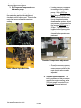
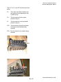
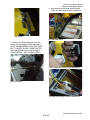
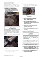
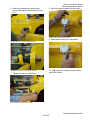
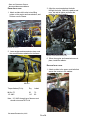
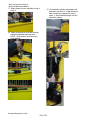
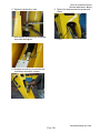
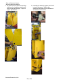
3. Tighten bolt and nut to 800 ft-lbs.
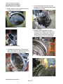
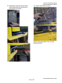
REMOVAL OF TRAVERSE CYLINDER
To remove the traverse cylinder, perform the
installation in reverse order.
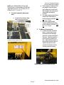
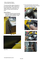
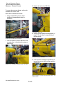
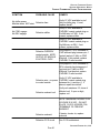
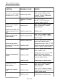
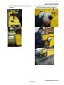
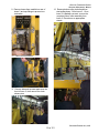
INSTALLATION OF TRAVERSE CYLINDER
1. Using a suitable lifting device, lift the
cylinder to the appropriate height for
installation.
TIGHTENING REAR BOLT.
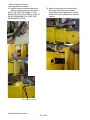
4. Swing cylinder toward frame and place on
stand. This will allow for repositioning of
the lifting strap.
LIFTING THE CYLINDER INTO POSITION.
2. Line the cylinder in position above the rear
mounting cone. Insert bolt with washer at
head of bolt.
PLACING CYLINDER ON STAND.
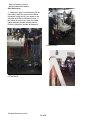
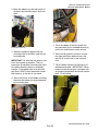
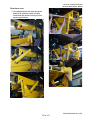
5. Pull or push the carriage to a position that
lines up the rod end of the cylinder with the
front mount.
LINING UP THE CYLINDER, MOUNTING CONE, AND BOLT.
RE-LOCATION OF LIFTING STRAP AND LINING UP OF THE
FRONT MOUNT.
PETTIBONE/TRAVERSE LIFT, LLC
PAGE 54
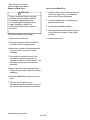
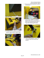
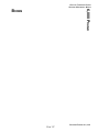
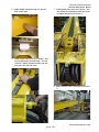
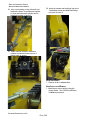
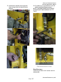
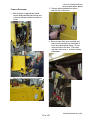
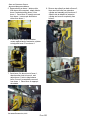
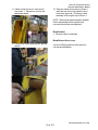
6. Hold the mounting cone in place while
lining up the cylinder and inserting the front
bolt.
POSITIONING THE FRONT MOUNTING CONE.
FIXED AND TRAVERSING FORKLIFT
ADVANCED MAINTENANCE MANUAL
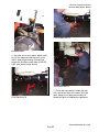
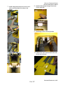
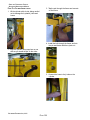
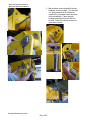
8. Remove protective caps from valve block.
PROTECTIVE CAPS ON VALVE BLOCK.
9. Attach hoses to fittings on valve block.
CYLINDER, MOUNTING CONE, BOLT, AND NUT.
10. Apply grease to using the fittings at each
end of the cylinder.
7. Tighten bolt and nut to 800 ft-lbs.
TIGHTENING OF FRONT BOLT AND NUT.
PETTIBONE/TRAVERSE LIFT, LLC
PAGE 55
FIXED AND TRAVERSING FORKLIFT
ADVANCED MAINTENANCE MANUAL
SYMPTOM
Cylinder will not operate
when joystick is actuated
Cylinder drifts (will not
remain in position)
TRAVERSE CYLINDER TROUBLESHOOTING
PROBABLE CAUSE
REMEDY
Failed hose or hose connections leaking.
Replace hose or tighten
loose connections.
Low oil level in reservoir.
Add oil to FULL mark on
reservoir GAUGE.
Insufficient pilot pressure
supplied to main valve.
Check pilot pressure with a
600 psi pressure gauge.
Correct pressure should be
300(±25) psi.
Oil bypassing spool in main
valve.
Replace defective spool
seal (s).
Rod wiper leaking excessively.
Replace defective wiper.
Oil bypassing cylinder
piston.
Replace defective piston
seal.
Faulty pump operation.
Repair or replace pump.
Load larger than capacity.
Reduce to rated load capacity at rated load center.
Oil bypassing spool in main
valve.
Replace defective spool
seal(s).
Oil bypassing cylinder
piston.
Replace defective piston
seal.
Oil bypassing counterbalance valve cartridge.
Replace defective cartridge
seal (s).
Spool not centered in main
valve.
Replace spool centering
springs.
Main relief valve not holding.
Clean cartridge or replace.
Load larger than capacity.
Reduce to rated load capacity at rated load center.
PETTIBONE/TRAVERSE LIFT, LLC
PAGE 56
FIXED AND TRAVERSING FORKLIFT
ADVANCED MAINTENANCE MANUAL
REMOVAL/INSTALLATION OF STEERING CYLINDER
! WARNING!
HEAVY COMPONENTS! BEFORE REMOVING/
INSTALLING CYLINDER, CHECK ITS WEIGHT AND MAKE
PROVISIONS FOR ATTACHING AND LIFTING.
CON-
SIDER WHAT REMOVAL OF THE COMPONENT WILL
DO TO THE STABILITY OF THE MACHINE.
USE A
HOIST CAPABLE OF SUPPORTING THE WEIGHT. A
SLIPPING OR FALLING COMPONENT MAY RESULT
IN SERIOUS INJURY OR DEATH TO PERSONNEL.
Refer to your Carraro Axle Manual for steering
cylinder removal and installation.
NOTE: THIS CYLINDER IS DESIGNED TO
BE REPLACED WHEN THERE IS A PROBLEM WITH IT, RATHER THAN BEING REBUILT. FOR REPLACEMENT PART NUMBERS REFER TO THE PARTS MANUAL.
PETTIBONE/TRAVERSE LIFT, LLC
PAGE 57
FIXED AND TRAVERSING FORKLIFT
ADVANCED MAINTENANCE MANUAL
REMOVAL OF FORK FRAME SIDE TILT CYLINDER
EXTENSION CYLINDER INSTALLATION/REMOVAL
Refer to boom section.
! WARNING!
HEAVY COMPONENTS! BEFORE REMOVING
CYLINDER, CHECK ITS WEIGHT AND MAKE
PROVISIONS FOR ATTACHING AND LIFTING. CONSIDER WHAT REMOVAL OF THE COMPONENT WILL
DO TO THE STABILITY OF THE MACHINE.
USE A
HOIST CAPABLE OF SUPPORTING THE WEIGHT. A
SLIPPING OR FALLING COMPONENT MAY RESULT
IN SERIOUS INJURY OR DEATH TO PERSONNEL.
1. Park machine on a firm, level surface.
Engage parking brake.
2. Lower fork frame to floor or ground to
prevent tipping of the fork frame when
cylinder is removed.
3. Clean hydraulic connections at cylinder
with a cleaning solvent.
4. Match-mark the hydraulic lines and cylinder
ports to ensure correct connections during
installation.
5. Disconnect hydraulic lines from cylinder.
Cap the lines and cylinder ports to prevent
contamination.
6. Secure a suitable lifting strap from hoist to
cylinder.
7. Remove capscrew, lockwasher, and nut
from cylinder rod pin. Pull out pin with a
suitable puller.
8. Remove capscrew, lockwasher and nut
from cylinder base pin. Pull out pin to
disconnect cylinder from machine.
9. Lift cylinder away from machine and place
on suitable supports.
PETTIBONE/TRAVERSE LIFT, LLC
PAGE 58
FIXED AND TRAVERSING FORKLIFT
ADVANCED MAINTENANCE MANUAL
BRAKES
PETTIBONE/TRAVERSE LIFT, LLC
PAGE 59
FIXED AND TRAVERSING FORKLIFT
ADVANCED MAINTENANCE MANUAL
BRAKE CIRCUIT
POWER BRAKE VALVE
In our brake system oil comes from the
hydraulic pump and flows through the main
directional valve to the steering/brake pressure reducing valve.
The power brake valve applies oil pressure to
the pistons in the disc brake calipers. The
pressure is created by actuation of the brake
pedal. The power brake valve is located under
the floor of the operators compartment.
The pressure readings that can be obtained
from the the main pressure test port will
should be 3450 psi, all others are load sense
at 3250 psi. Here are some conditions and
corresponding pressures that could be obtained at this location:
REMOVAL OF POWER BRAKE VALVE
At machine startup with no functions being
actuated: 500-1000 psi, until the accumulator
is charged, then system pressure of 500 psi.
Machine running with no functions being
actuated: 500 psi.
Brakes only: 500 psi, until the accumulator
pressure drops below 1000 psi, then 5001000 psi. This is only until the Low Limit
Pressure Switch reads accumulator pressure of 1000 psi or more, then the reading
will be 500 psi.
Machine operating normally: 500-3450 psi.
Machine sitting idle, initially reading 500 psi
and then turning the steering wheel: 5002500 psi.
Deadheading any function: 3000-3450 psi.
1. Remove the (5) capscrews, (5)
lockwashers and (5) flat washers from the
access cover under the floor of the
operators compartment. Remove the
cover.
Pressures read at this port may be between
500-3450 psi, depending upon which functions
are being actuated, if any at all.
ACCESS COVER LOCATION
BRAKE PRESSURE CHECK
2. Thoroughly clean the power brake valve and
hydraulic connections with an approved
cleaning solvent.
The brake pressure test port and the steering
pressure test port are the same, so they will
have the same pressure reading. For doing
an adjustment, refer to the steering pressure
adjustment.
POWER BRAKE VALVE
PRESSURE TEST PORTS
PETTIBONE/TRAVERSE LIFT, LLC
PAGE 60
FIXED AND TRAVERSING FORKLIFT
ADVANCED MAINTENANCE MANUAL
3. Match-mark the hydraulic lines and valve
ports to ensure correct connections during
installation.
4. Start engine and actuate brake pedal to
ensure correct operation. Inspect valve for
leaks.
4. Disconnect hydraulic lines from valve. Cap
the lines and valve ports to prevent contamination.
5. Install the access cover under the
operators compartment and secure with
the (5) capscrews, (5) lockwashers and
(5) flat washers.
5. Remove the (3) capscrews which secure
the valve base to the floor. Remove valve.
BRAKE PEDAL SCHEMATIC SYMBOL
BRAKE VALVE MOUNTING CAPSCREWS
POWER BRAKE VALVE SERVICE INFORMATION
For complete service information on the power
brake valve, refer to the Mico Service Publication included in this manual.
INSTALLATION OF POWER BRAKE VALVE
1. Install the valve in the floor of the operators
compartment and secure with the (3)
capscrews.
BRAKE CHARGING MANIFOLD SCHEMATIC SYMBOL
2. Connect hydraulic lines to valve.
3. Bleed the brake lines by following the
procedure indicated in the Mico Service
Publication.
PETTIBONE/TRAVERSE LIFT, LLC
PAGE 61
FIXED AND TRAVERSING FORKLIFT
ADVANCED MAINTENANCE MANUAL
SERVICE CHECKS FOR BRAKE SYSTEM
SYMPTOM
Accumulator charging cycle
repeats frequently when
accumulator is not normally
being discharged in service
Accumulator starts to
charge but does not reach
high limit
Accumulator charging time
too long
Accumulator fails to start
charging
PROBABLE CAUSE
REMEDY
Leaking accumulator lines
or fittings.
Incorrect setting of
accumulator gas charge.
Check accumulator gas
charge.
Line to accumulator
plugged.
Replace line.
Defective pressure switch.
Replace switch.
No oil or low oil level in tank.
Check oil level.
Pump worn or inoperative
and not delivering full flow or
pressure.
Check pump.
Inoperative charging valve.
Replace charging valve.
No oil or low oil level in tank.
Check oil level.
Relief valve setting too low.
Check valve setting.
Pump worn or inoperative
and not delivering full flow or
pressure.
Check pump.
Inoperative charging valve.
Replace charging valve.
No oil or low oil level in tank.
Check oil level.
Worn or inoperative pump.
Check pump pressure and
flow.
Inoperative relief valve.
Check relief valve settings.
Air in accumulator line.
Bleed accumulator line.
PETTIBONE/TRAVERSE LIFT, LLC
PAGE 62
SERVICE CHECKS FOR BRAKE SYSTEM
SYMPTOM
Very rapid cycling of charging valve
Lack of adequate flow
through valve
Accumulator charges
continously
PROBABLE CAUSE
FIXED AND TRAVERSING FORKLIFT
ADVANCED MAINTENANCE MANUAL
REMEDY
Incorrect setting of accumulator gas charge.
Check accumulator gas
charge.
Inoperative charging valve.
Replace charging valve.
Inoperative pump.
Check pump pressure and
delivery.
Blocked lines.
Replace lines.
Inoperative charging valve.
Replace charging valve.
Bad solenoid valve.
Check voltage at solenoid
valve in manifold block. If
voltage is present, replace
solenoid valve.
Defective or disconnected
wire.
If voltage is not present at
solenoid, check continuity
with mico switch and
replace wires.
Defective pressure switch
If mico switch is not sending
a signal to the solenoid
valve, replace switch.
PETTIBONE/TRAVERSE LIFT, LLC
PAGE 63
FIXED AND TRAVERSING FORKLIFT
ADVANCED MAINTENANCE MANUAL
ACCUMULATORS
The type of accumulators that the machines
use are Parker piston type. Some useful
information follows:
Pre charge - 750 psi. of Nitrogen
Failure prevention
Accumulator failure generally is defined as its
inability to accept and exhaust a specified
amount of fluid when operating over a specific
system pressure range. Failure often results
from an unwanted loss or gain of precharge
pressure.
Piston accumulators normally fail in one of
these gradual modes:
Fluid leaks to the gas side. This failure,
sometimes called dynamic transfer, normally
takes place during rapid cycling operations
after considerable time in service. The worn
piston seal wipes a small amount of fluid into
the gas side with each stroke; as the gas side
slowly fills with fluid, precharge pressure
rises, and the accumulator stores and exhausts decreasing amounts of fluid. The
accumulator totally fails when precharge
pressure equals maximum hydraulic system
pressure. At that point, the accumulator will
accept no fluid. Because the rise in
precharge pressure can be measured, failure
can be predicted and repairs made before
total failure occurs, and gas escapes.
Precharge usually is lost as gas slowly
bypasses deteriorated piston seals. Seal
deterioration occurs from the wear of millions
of cycles, from fluid contamination or from a
combination of the two. Gas also can directly
vent through a defective gas valve core or
end-cap O-ring. Less precharge pressure
forces less fluid into the system. Because
this gradual decrease in precharge pressure
also can be measured, repairs again can be
made before total failure.
A TYPICAL PISTON TYPE ACCUMULATOR
A bladder type failure is shown in (a). As fluid
leaks past piston (b), gas side of piston
accumulator fills with fluid to increase
precharge pressure. If precharge gas leaks
past piston or vents through gas valve, (c),
accumulator gradually forces less fluid into
system for lower efficiency.
PETTIBONE/TRAVERSE LIFT, LLC
PAGE 64
FIXED AND TRAVERSING FORKLIFT
ADVANCED MAINTENANCE MANUAL
FAILURE PREDICTION
Several methods can be used to monitor the
precharge pressure of piston accumulators:
with the hydraulic system shut down. A
pressure transducer or gauge located in the
gas-end cap,(a), indicates the true precharge
pressure after a working hydraulic system has
cooled and the accumulator does not contain
fluid
with the hydraulic system operating. On
request, accumulator manufacturers will
install a piston-position sensor in an
accumulators hydraulic-end cap, (b). This
sensor can be connected to a number of
electronics packages. With an accurate
precharge and after enough system operation
for thermal stability, the electronics can be
calibrated to provide continuous readout of
precharge pressure that corresponds accurately to the true precharge, and
another alternative. In applications where an
accumulator is coupled to a gas bottle, a Hall
Effect sensor can be installed in the accumulator gas-end cap, (c), to detect when the
piston comes within 0.040 inches of the cap.
This warning indicates that precharge pressure has dropped and the system should be
shut down and checked.
SETUP AND MAINTENANCE
Precharge Technique
The fluid side should be empty during
precharging so that gas-side volume is at a
maximum. Little damage, if any, can take
place during precharging.
Precharge pressure
Excessively high precharge.
Excessive precharge pressure or a reduction
in the minimum system pressure without a
corresponding reduction in precharge pressure may cause operating problems or damage.
With excessive precharge pressure, a piston
accumulator will cycle between stages
PETTIBONE/TRAVERSE LIFT, LLC
PAGE 65
FIXED AND TRAVERSING FORKLIFT
ADVANCED MAINTENANCE MANUAL
(e) and (b), and the piston will range to close
to the hydraulic-end cap. The piston could
bottom at minimum system pressure to
reduce output and eventually cause damage
to the piston and the piston seal. The bottoming of the piston often can be heard; the sound
serves as a warning of impending problems.
The schematic representation of an accumulator is shown here:
Excessively low precharge.
Excessively low precharge pressure or an
increase in system pressure without a compensating increase in precharge pressure
also can cause operating problems and may
promote accumulator damage. With no
precharge in a piston accumulator, the piston
likely will be driven into the gas-end cap and
probably will remain there. Most likely, no
damage will occur with this single contact.
LOCATION OF
ACCUMULATOR
PETTIBONE/TRAVERSE LIFT, LLC
PAGE 66
FIXED AND TRAVERSING FORKLIFT
ADVANCED MAINTENANCE MANUAL
PRE-CHARGING
(H) When finished precharging accumulator,
turn T handle all the way out on gas
chuck, then open bleed valve.
(I) Hold gas valve to keep from turning,
loosen swivel nut, remove assembly.
(J) Replace gas valve cap (10-15 in. lbs.)
(11.5-17 cm kg) and valve guard. (Gas
cap serves as a secondary seal.)
Use an inert gas such as nitrogen for
precharging accumulators.
If water pumped nitrogen is not available, oilpumped nitrogen may be used. C.G.A. standards: Nitrogen gas bottles for water pumped
nitrogen has a right-hand valve thread which
requires charging and gauging assembly LL1803-490 for units up to 3000 psi.
If equipment other than the above listed is
used, make sure it is compatible with the gas
valve assembly. Nitrogen source and all
components must be rated for a pressure at
least as high as the nitrogen source. It is
strongly recommended that the nitrogen bottle
used have a high pressure regulator.
Make sure nitrogen supply is shut off. Attach
hose to nitrogen bottle.
(A) Remove gas valve guard and gas valve
cap.
(B) Back gas chuck T' handle all the way out
(counter clockwise) before attaching
charging assembly to accumulator gas
valve.
(C) Close bleed valve.
(D) Making sure not to loop or twist the hose
attach swivel nut to gas valve and tighten
(10-15 in. lb.) (11.5-17 cm kg).
(E) Turn gas chuck "T" handle all the way
down. This will depress core in gas valve.
(F) Crack open nitrogen bottle valve and
slowly fill accumulator. Shut off when
gauge indicates desired precharge.
(G) Let the precharge set for 10 to 15
minutes. This will allow the gas temperature to stabilize. If the desired precharge
is exceeded, close nitrogen bottle valve,
then slowly open bleeed valve. Do not
reduce precharge by depressing valve
core with a foreign object. High pressure
may rupture rubber valve seat.
PETTIBONE/TRAVERSE LIFT, LLC
PAGE 67
FIXED AND TRAVERSING FORKLIFT
ADVANCED MAINTENANCE MANUAL
MAINTENANCE
Repair Kits (see Parts Book) are available for
all accumulator models. When ordering repair
kits, state complete model number from
nameplate. Also specify fluid and temperature
at which used.
(5) Turn gas chuck T handle all the way
down. This will depress core in gas valve
and check pressure.
(6) To remove gauging assembly turn T
handle all the way out on gas check
(Figure 1), then open bleed valve.
Occasional replacement of v-o-ring seal on
the piston is generally the only maintenance
required. Replacement of other seals on end
caps and gas valve is recommended (see Kit
Numbers).
(7) Hold gas valve from turning, loosen swivel
nut, remove assembly.
Periodic checking of precharge pressure will
detect whether v-o-ring wear is sufficient to
begin reducing sealing performance. If
precharge is low, also check for gas valve
and/or end seal leakage. Allowing for temperature difference, if any, from time of its
pressure checking, precharge pressure will
rise if oil gathers in the gas side and will fall if
gas leaks into the oil side or out past gas end
seals. It is suggested that a check be made a
week after installation, and thereafter once a
month.
Remove from Hydraulic System
PRECHARGE CHECKING PROCEDURE
Remove accumulator from hydraulic system.
Threaded holes in hydraulic cap may be used
as a means of attachment for lifting, or use a
sling around the body.
(8) Replace gas valve cap (10-15 in. lbs.)
(11.5-17 cm kg) and valve guard.
Using appropriate valve in the hydraulic
system, discharge all oil from accumulator
and allow piston to bottom against hydraulic
end cap.
Shut equipment down and make certain that
hydraulic pressure at the accumulator is at
zero. At this point the piston will be bottomed
at the hydraulic end.
For accumulators having gas valve, attach
gauging assembly, then follow steps 1
through 5. Open bleed valve until all gas
precharge is relieved from accumulator. Next,
remove gauging assembly and gas valve.
For the accumulator used on the forklift, use
gauging assembly, Part # LL-1803-490.
For accumulators having gas valve:
(1) Remove gas valve guard and cap.
(2) Back gas check T handle all the way out
(counter clockwise) before attaching
charging assembly to accumulator gas
valve.
3) Close bleed valve.
(4) Attach swivel nut to gas valve and tighten
(10-15 in. lb.) (11.5-17 cm kg).
PETTIBONE/TRAVERSE LIFT, LLC
PAGE 68
FIXED AND TRAVERSING FORKLIFT
ADVANCED MAINTENANCE MANUAL
DISASSEMBLY OF ACCUMULATOR
REASSEMBLY
Lay the accumulator horizontally and hold
down with a strap wrench or in a vise. Some
accumulators may have both end caps
threaded into the body and some units may
only have the gas cap threaded into the body.
IN BOTH CASES ALWAYS REMOVE THE
GAS CAP FIRST (end cap which contained
gas valve). To remove cap or caps, install
three (3) pins into the holes in the cap, then,
using a long bar working against the pins,
unthread the cap from the body. Remove orings and back-up rings from end cap.
Coat all internal parts with clean hydraulic fluid
before reassembly.
Remove piston by pushing from hydraulic end
with a bar. NEVER TRY TO REMOVE PISTON BY APPLYING COMPRESSED AIR AT
OPPOSITE END. To remove v-o-ring from
piston, lift seal with small smooth screw driver
or similar tool, moving the tool around the
piston several times while using the other
hand to work ring off the piston.
CLEANING
Thoroughly clean metal parts in solvent and
dry with compressed air. Clean bore of body
with a clean, lint-free cloth soaked in clean
solvent. Bore must be clean of any visible
particles or particles detectable to touch.
With new v-o-ring and Teflon rings on piston,
install piston, hollow side toward gas end, in
bore of body. Do not let v-o-ring drag on
threads. Piston must go into bore exactly
square and very slowly. (V-o-ring will compress as it rides up the chamfer if done slowly,
but may be damaged if forced quickly.) Piston
will fit snug. Use hammer and wood block to
tap piston into place until all of piston is 2
inches below beginning of honed bore. Keep
force against piston while tapping v-o-ring
through the bore chamfer, otherwise piston
will bounce back, damaging the o-ring. Cover
port opening to keep dirt out.
Install new back-up ring first, then a new o-ring
on threaded end cap or caps and install into
body bore. Care should be exercised not to
drag o-ring over threads. End cap will stop
against chamfer leading into honed bore
(extreme tightness not required, o-ring sealing
is not dependent upon cap tightness). Cap
should be flush with or above the end of
accumulator body within 1/32 to 3/32.
Install gas valve after replacing the o-ring.
INSPECTION
Inspect piston for cracks, burrs around o-ring
grooves, or damage. Examine body bore,
using a light, for scratches or scoring. Inspect
end caps for damaged threads of burrs on oring grooves.
REPAIR AND REPLACEMENT
Minor nicks, scratches or light scoring of the
body bore can be removed by using crocus
cloth. Dress bore until all apparent imperfections have been removed. Replace teflon
wear rings, v-o-rings, o-rings and their respective back up washers if the original assembly
contained them.
Remount accumulator and connect to hydraulic system. Precharge accumulator (where
space is a problem it may be necessary to
precharge accumulator before connecting it to
the hydraulic system).
ACCUMULATOR CHARGING VALVE
The accumulator charging valve is nothing
more than a solenoid valve that is controlled
by a Hi-Low limit switch. This solenoid valve
directs the oil to the accumulator when the
charged pressure drops below 1000psi, and
returns the load sense signal back to tank.
Under normal operating conditions, where the
accumulator pressure is above 1000psi,
system pressure is constantly applied to the
accumulator and to the load sense signal.
This allows the accumulator to stay charged
during normal operation.
PETTIBONE/TRAVERSE LIFT, LLC
PAGE 69
FIXED AND TRAVERSING FORKLIFT
ADVANCED MAINTENANCE MANUAL
ACCUMULATOR TROUBLESHOOTING
6<03720
352%$%/(&$86(
5(0('<
$FFXPXODWRUFKDUJHVGXULQJ
HQJLQHFUDQNLQJ
2SHQGLRGHLQKDUQHVV
9HULI\9'&SUHVHQWEHWZHHQ
SLQ$ZKWDQGSLQ%EONRQ
6VROHQRLGYDOYHRQFKDUJLQJ
PDQLIROG,IDEVHQWUHSODFH
GLRGH
$FFXPXODWRUGRHVQRWFKDUJH
&KDUJLQJSUHVVXUHVZLWFK
VKRUWHG
8QSOXJFKDUJLQJSUHVVXUH
VZLWFK,IFKDUJLQJEHJLQV
UHSODFHSUHVVXUHVZLWFK
'HIHFWLYHVROHQRLG
5HSODFHVROHQRLG
'HIHFWLYHIXVH
5HSODFHIXVH
$FFXPXODWRUFKDUJHVDWDOO
WLPHVSUHVVXUHRYHUSVL
8QSOXJSUHVVXUHVZLWFKDQG
DQGMXPSKDUQHVVVLGHSOXJSLQ
'HIHFWLYHSUHVVXUHVZLWFKRSHQ
$WR%,IFKDUJLQJVWRSV
UHSODFHSUHVVXUHVZLWFK
2SHQGLRGHLQKDUQHVV
9HULI\9'&SUHVHQWEHWZHHQ
SLQ$RUJDQGJURXQGDW
FKDUJLQJSUHVVXUHVZLWFK,I
DEVHQWUHSODFHGLRGH
'HIHFWLYHVROHQRLGFRLO
9HULI\FRLOUHVLVWDQFH#
RKPV,IRSHQRUKLJKUHSODFH
FRLO
'HIHFWLYHVROHQRLG
,IHOHFWULFDOFKHFNRNUHSODFH
VROHQRLG
/REUDNHRLOOLJKWGRHVQRWJR
RXW
'HIHFWLYHOREUDNHRLOSUHVVXUH
VZLWFK
8QSOXJSUHVVXUHVZLWFKLIOLJKW
JRHVRXWUHSODFHVZLWFK
/REUDNHRLOOLJKWGRHVQRWOLJKW
SUHVVXUHEHORZSVL
'HIHFWLYHEXOERQODPSDVV\
'HIHFWLYHOREUDNHRLOSUHVVXUH
VZLWFK
PETTIBONE/TRAVERSE LIFT, LLC
PAGE 70
5HSODFHEXOERQODPSDVV\
-XPSSLQ$EUQWRSLQ%EON
RQOREUDNHSUHVVXUHVZLWFK
,IOLJKWJORZVUHSODFHSUHVVXUH
VZLWFK
FIXED AND TRAVERSING FORKLIFT
ADVANCED MAINTENANCE MANUAL
DRIVESHAFTS
PETTIBONE/TRAVERSE LIFT, LLC
PAGE 71
FIXED AND TRAVERSING FORKLIFT
ADVANCED MAINTENANCE MANUAL
DISASSEMBLY OF DRIVESHAFT
5. Remove retainer cap, (2) washers and felt
seal from end of slip yoke.
1. Remove the (4) capscrews and (4)
lockwashers which secure the cross and
bearing assembly to the stub yoke. Remove cross and bearing assembly.
RETAINER CAP AND SEALS
2. Remove the (4) capscrews and (4) lockwashers which secure the other cross and
bearing assembly to the slip yoke. Remove
cross and bearing assembly.
3. Unscrew grease fittings from cross and
bearing assemblies.
4. Separate the driveshaft assembly by
loosening the retainer cap and sliding the
slip yoke from the stub yoke. Use caution to
prevent damaging the splines. Unscrew
grease fitting from slip yoke.
6. Inspect stub yoke and slip yoke splines for
excessive wear. Check slip yoke and
retainer cap for damaged threads.
7. Inspect cross and bearing for side play. If
worn, replace complete cross and bearing
assembly.
NOTE: OPPOSITE BEARINGS ARE HELD IN
PLACE ON THE CROSS BY A WELD WIRE.
CUTTING THIS WIRE WILL ALLOW REMOVAL OF BEARINGS FROM CROSS.
HOWEVER, IF CROSS END BEARINGS
ARE REPLACED AS AN ASSEMBLY, CUTTING IS UNNECESSARY.
ASSEMLY OF DRIVESHAFT
1. Replace the (2) washers, felt seal and
retainer cap on end of slip yoke. (Felt seal,
goes between the washers.)
2. Install grease fitting in slip yoke.
PETTIBONE/TRAVERSE LIFT, LLC
PAGE 72
3. Slide slip yoke and stub yoke together,
being certain to properly engage splines.
Make sure that yokes on both ends of the
driveshaft are in the same plane. This
alignment is necessary for correct timing.
FIXED AND TRAVERSING FORKLIFT
ADVANCED MAINTENANCE MANUAL
7. Secure opposite bearings of cross to
driveshaft yoke with the (4) capscrews
and (4) lockwashers. Remove C clamp.
8. Repeat steps 6 and 7 for other cross and
bearing assembly.
9. Check tightness of transmission yoke
retaining nuts.
DRIVESHAFT ALIGNMENT
4. Tighten retainer cap on slip yoke.
5. Install grease fittings in cross and bearing
assemblies.
6. Position a cross and bearing assembly on
either end of driveshaft. Insert opposite
bearings of cross into keyed portion of
driveshaft yoke.
TRANSMISSION YOKE RETAINING NUT
INSTALLATION OF DRIVESHAFT
! WARNING!
HEAVY COMPONENTS! BEFORE INSTALLING
DRIVESHAFT, CHECK ITS WEIGHT AND MAKE
PROVISIONS FOR ATTACHING AND LIFTING. USE
A HOIST CAPABLE OF SUPPORTING THE WEIGHT.
A SLIPPING OR FALLING COMPONENT MAY RESULT
IN SERIOUS INJURY OR DEATH.
1. Secure a suitable lifting strap from hoist to
driveshaft. Lift the driveshaft into position
between transmission and axle.
INSERT CROSS BEARINGS INTO YOKE KEYWAYS
Clamp opposite bearings with a C clamp to
compress seals and seat each bearing into
its keyway. DO NOT INSTALL BEARING
CAPSCREWS UNTIL BEARINGS ARE
PROPERLY SEATED.
2. Bring one end of driveshaft up against drive
yoke on axle or transmission. Insert
opposite bearings of cross into keyed
portion of drive yoke.
Clamp opposite bearings with a C clamp to
compress seals and seat each bearing into
its keyway. DO NOT INSTALL BEARING
CAPSCREWS UNTIL BEARINGS ARE
PROPERLY SEATED.
PETTIBONE/TRAVERSE LIFT, LLC
PAGE 73
FIXED AND TRAVERSING FORKLIFT
ADVANCED MAINTENANCE MANUAL
3. Secure opposite bearings of cross to drive
yoke with the (4) capscrews and (4)
lockwashers. Remove clamp.
4. Repeat steps 2 and 3 for other end of
driveshaft.
5. Remove block and jack from axle.
6. Lubricate the driveshaft and cross and
bearing assemblies with the recommended lubricant specified.
PETTIBONE/TRAVERSE LIFT, LLC
PAGE 74
DRIVESHAFT TROUBLESHOOTING
SYMPTOM
Noise
PROBABLE CAUSE
FIXED AND TRAVERSING FORKLIFT
ADVANCED MAINTENANCE MANUAL
REMEDY
Lack of lubricant.
Check bearing cap grease
seals for wear. Replace if
worn. Lubricate with correct
grade of grease specified.
Driveshaft assembly is out
of balance.
Check for proper alignment.
Clean dirt from driveshaft.
Check for missing balance
weights.
Vibration
Backlash due to worn cross
or bearing.
Replace cross and bearing
assembly as a complete
unit.
Off center rotation due to
worn slip joint.
Replace slip joint or
driveshaft assembly.
Yokes are not in line.
Check for proper driveshaft
alignment. (See Assembly
of Driveshaft.)
Driveshaft out of balance.
Replace driveshaft assembly.
Driveshaft sprung from
contact with obstruction.
Replace driveshaft assembly.
Excessive run out or distorted yokes.
Disassemble and correct or
replace damaged parts.
Loose flange nut on transmission or differential
flange.
Tighten nut and check
splines. If worn, replace
driveshaft assembly.
Parking brake drum warped.
Replace parking brake.
Off center rotation due to
worn slip joint.
Replace slip joint or driveshaft assembly.
PETTIBONE/TRAVERSE LIFT, LLC
PAGE 75
FIXED AND TRAVERSING FORKLIFT
ADVANCED MAINTENANCE MANUAL
NOTES
PETTIBONE/TRAVERSE LIFT, LLC
PAGE 76
FIXED AND TRAVERSING FORKLIFT
ADVANCED MAINTENANCE MANUAL
TRANSMISSION
PETTIBONE/TRAVERSE LIFT, LLC
PAGE 77
FIXED AND TRAVERSING FORKLIFT
ADVANCED MAINTENANCE MANUAL
ENGINE/TRANSMISSION ASSEMBLY
1. Install a dowel pin onto the torque converter
for aligning it to the flywheel.
DOWEL ON TRANSMISSION
3. Lift the transmission with two eye bolts
attached on the side mounting holes of the
transmission housing.
LIFTING TRANSMISSION
4. Using the aligning dowels, move the
transmission up against the engine and
start all of the mounting bolts. While the
transmission is still being supported by
the lift, tighten all of the mounting bolts.
ALIGNMENT LOCATION ON ENGINE
2. Install two more dowels into the bell housing, on the engine, for aligning the transmission housing with the engine housing.
ALIGNING TRANSMISSION
DOWELS ON ENGINE
STARTING BOLTS
PETTIBONE/TRAVERSE LIFT, LLC
PAGE 78
5. Open the access cover on the engine to
insert and tighten the bolts, to 35 Ft-Lbs,
that mate the flywheel and the transmission torque converter. Rotate the engine
to each successive threaded hole until all
of the (8) eight bolts are secured.
FIXED AND TRAVERSING FORKLIFT
ADVANCED MAINTENANCE MANUAL
DISASSEMBLY
To disassemble, do the previous steps in
reverse order.
INDEPTH SERVICE
Please refer to the Carraro TLB2 manual that
was shipped with your machine for further
disassembly and troubleshooting.
6. Remove the dowels from the housing and
install the remaining bolts to secure the
transmission to the engine.
PETTIBONE/TRAVERSE LIFT, LLC
PAGE 79
FIXED AND TRAVERSING FORKLIFT
ADVANCED MAINTENANCE MANUAL
TRANSMISSION TROUBLESHOOTING
SYMPTOM
Transmission slips
Transmission will not
change into selected gear
PROBABLE CAUSE
REMEDY
Low transmission oil level
Fill transmission with
proper oil to proper level
Worn clutches
See authorized dealer
Contaminated transmission
Drain transmission,
filter element, and refill
with clean oil. If problem
persists, see authorized
dealer
Linkage loose or out of
adjustment
Connect and/or adjust
linkage
Internal damage to
transmission valve
See authorized dealer
for service
Low transmission oil level
Fill transmission with
proper oil to proper level
CARRARO TRANSMISSION CONTROL TROUBLESHOOTING
6<03720
1RVWJHDUVDPH
SURFHGXUHIRUQGUG
DQGWK
352%$%/(&$86(
5(0('<
'HIHFWLYHVKLIWHU
9HULI\9'&DYDLODEOHEHWZHHQ
SLQDQGSLQRIVWJHDUVROHQRLG
SOXJ,IDEVHQWUHSODFHVKLIWHU
'HIHFWLYHVROHQRLGFRLO
9HULI\FRLOUHVLVWDQFHRKPV,I
RSHQRUKLJKUHSODFHFRLO
'HIHFWLYHVROHQRLG
,IHOHFWULFFKHFNVRNUHSODFH
VROHQRLG
PETTIBONE/TRAVERSE LIFT, LLC
PAGE 80
FIXED AND TRAVERSING FORKLIFT
ADVANCED MAINTENANCE MANUAL
CARRARO TRANSMISSION CONTROL TROUBLESHOOTING
6<03720
352%$%/(&$86(
5(0('<
1RVKLIWHUSRZHU
'HIHFWLYHIXVH
0DFKLQHGRHV127VWDUW
9HULI\9'&DYDLODEOHWRSLQ
EOXRQVKLIWHUSOXJ,IQRQH
UHSODFHIXVH
1R):'HQJDJH
1R5(9HQJDJH
9HULI\9'&DYDLODEOHWR
):'5(9FRQWUROPRGXOHSOXJRQ
3XU:KWZLUHLQ):',IQRW
SUHVHQWUHSODFHVKLIWHU
'HIHFWLYHVKLIWHU
9HULI\9'&DYDLODEOHWR
):'5(9FRQWUROPRGXOHSOXJRQ
2UJ:KWZLUHLQ5(9,IQRW
SUHVHQWUHSODFHVKLIWHU
'HIHFWLYH):'5(9
FRQWUROPRGXOH127(
2873872)02'8/(
,6$3352;9'&
9HULI\DSSUR[9'&DYDLODEOHWR
):'VROHQRLGSOXJEHWZHHQSLQ
JUQ\HODQGSLQEONRQ):'
VROHQRLG,IQRWSUHVHQWUHSODFH
):'5(9&RQWUROPRGXOH
9HULI\DSSUR[9'&DYDLODEOHWR
5(9VROHQRLGSOXJEHWZHHQSLQ
JU\DQGSLQZKWRQ5(9
VROHQRLG,IQRWSUHVHQWUHSODFH
):'5(9&RQWUROPRGXOH
9HULI\9'&DYDLODEOHWR
'HIHFWLYHZLUHQRSRZHU ):'5(9FRQWUROPRGXOHSOXJ
WRFRQWUROPRGXOH
EHWZHHQEOXDQGEUQ,I
DEVHQWUHSDLUZLUHGHIHFW
'HIHFWLYHVROHQRLGFRLO
9HULI\FRLOUHVLVWDQFHRKPVRI
DIIHFWHGFRLO,IRSHQRUKLJK
UHSODFHFRLO
127(0$;,080):'5(9&2,/
92/7$*(,69'&'2127
3/$&(9'&$&5266&2,/
7(50,1$/67235(9(17
%851287
'HIHFWLYHVROHQRLG
,IHOHFWULFFKHFNVRNUHSODFH
VROHQRLG
'HIHFWLYH&&2FLUFXLW
6HH&&2WURXEOHVKRRW
PETTIBONE/TRAVERSE LIFT, LLC
PAGE 81
FIXED AND TRAVERSING FORKLIFT
ADVANCED MAINTENANCE MANUAL
NOTES
PETTIBONE/TRAVERSE LIFT, LLC
PAGE 82
FIXED AND TRAVERSING FORKLIFT
ADVANCED MAINTENANCE MANUAL
AXLES
PETTIBONE/TRAVERSE LIFT, LLC
PAGE 83
FIXED AND TRAVERSING FORKLIFT
ADVANCED MAINTENANCE MANUAL
AXLE INSTALLATION
1. Using some type of overhead sling, lift the
front axle up near the mounts on the frame.
Be careful to align the (4) four dowels on the
axle with the holes on the frame mounts. If
the dowels do not line up, check the rubber
gasket between the axle housing and the
trunnions (where the dowels are attached).
ALIGNING AXLE
ATTACHING SLING AND CHAINS
LIFTING AXLE
PETTIBONE/TRAVERSE LIFT, LLC
PAGE 84
FIXED AND TRAVERSING FORKLIFT
ADVANCED MAINTENANCE MANUAL
TIGHTENING BOLTS
ALIGNING AXLE
2. Once the axle is set in place, attach it with
the (4) four capscrews that secure it to the
frame. Apply a light coating of thread lock,
snug them, and then torque them to 360-470
ft-lbs. (wet) with a torque wrench.
TORQUING BOLTS
STARTING BOLTS
3. Follow the same steps to attach the rear
axle, and torque them to the same 300 ft-lbs.
(wet), being sure to apply a thin coating of
thread lock prior to installing the capscrews.
PETTIBONE/TRAVERSE LIFT, LLC
PAGE 85
FIXED AND TRAVERSING FORKLIFT
ADVANCED MAINTENANCE MANUAL
MOVING REAR AXLE INTO PLACE
SECURING AXLE
4. When the axles are attached and secured,
connect the brake and steering hydraulic lines.
ATTACHING SLING AND CHAINS
LIFTING AXLE
FRONT AXLE BRAKE AND STEERING LINES
PETTIBONE/TRAVERSE LIFT, LLC
PAGE 86
FIXED AND TRAVERSING FORKLIFT
ADVANCED MAINTENANCE MANUAL
STEERING AND BRAKE LINE FITTINGS
REAR AXLE STABILIZATION MANIFOLD HYDRAULIC
SCHEMATIC SYMBOL
REAR AXLE BRAKE AND STEERING LINES
5. Lastly, put the tires back onto the axles.
A XLE REMOVAL
For the removal steps, just follow the installation steps in the reverse order.
INDEPTH SERVICE
Please refer to the correct Carraro axle
manual that was shipped with your machine
for further disassembly and troubleshooting.
PETTIBONE/TRAVERSE LIFT, LLC
PAGE 87
FIXED AND TRAVERSING FORKLIFT
ADVANCED MAINTENANCE MANUAL
REAR AXLE STABILIZATION MODES
PETTIBONE/TRAVERSE LIFT, LLC
PAGE 88
FIXED AND TRAVERSING FORKLIFT
ADVANCED MAINTENANCE MANUAL
REAR AXLE STABILIZATION TROUBLESHOOTING
6<03720
352%$%/(&$86(
5(0('<
5HDUD[OHQRWIUHHZLWK
ERRPGRZQSDUNEUDNH
VZLWFK2))
ORFN
OLJKW
2))
UHVWULFW
OLJKW2))
'HIHFWLYHRVFLOODWLRQOLPLW
IXVH
9HULI\9'&DYDLODEOHWRERRP
OLPLWVZLWFKSOXJSLQ$,IDEVHQW
UHSODFHIXVH
'HIHFWLYHRVFLOODWLRQOLPLW
UHOD\
7HPSRUDULO\UHSODFHUHOD\ZLWK
UHOD\,ID[OHUHOHDVHVUHSODFH
UHOD\
'HIHFWLYHVROHQRLGV
FRLO
9HULI\VROHQRLGFRQWLQXLW\UHVLVWDQFH
RKPVRQ66YDOYHVRI
RVFLOODWLRQPDQLIROGEORFN,IHLWKHU
RUERWKRSHQRUKLJKUHVLVWDQFH
UHSODFHVROHQRLGV
'HIHFWLYHVROHQRLGV
5HSODFHVROHQRLGV
5HDUD[OHLQUHVWULFWHG
PRGHERRPGRZQSDUN
EUDNH2))5HVWULFWOLJKW
21
%RRPOLPLWVZLWFKPLV
DGMXVWHG
5HDGMXVWVZLWFKWRRSHQ#
ERRP83
5HDUD[OHLQORFNPRGH
3DUNEUDNH21ORFNOLJKW
21
'HIHFWLYHERRPOLPLW
VZLWFK
-XPSSLQ$WRSLQ%RIERRPOLPLW
VZLWFKKDUQHVVSOXJ,ID[OHJRHVWR
IUHHPRGHUHSODFHDQGUHDGMXVW
ERRPOLPLWVZLWFK
'HIHFWLYHRVFOLPLWUHOD\
7HPSRUDULO\UHSODFHUHOD\ZLWK
UHOD\,ID[OHUHOHDVHDQGPRGH
OLJKWVJRRXWUHSODFHUHOD\
5HDUD[OHJRHVIURPIUHH
WRORFN#ERRP83
'HIHFWLYHRVFORFNUHOD\
ORFNOLJKW21SDUNEUDNH
2))
7HPSRUDULO\UHSODFHUHOD\ZLWK
UHOD\,ID[OHUHYHUWVWROLPLW
PRGHOLPLWOLJKW21UHSODFHUHOD\
5HDUD[OHGRHVQRWORFN
ZKHQSDUNEUDNHVZLWFK
21ERRPDERYHLQ
UHVWULFWPRGHUHVWULFW
OLJKW21
'HIHFWLYHRVFORFNUHOD\
7HPSRUDULO\UHSODFHUHOD\ZLWK
UHOD\,ID[OHUHYHUVWRORFN
PRGHORFNOLJKW21UHSODFHUHOD\
'HIHFWLYHVROHQRLGFRLOV
9HULI\66FRLOFRQWLQXLW\
UHVLVWDQFHRIRKPV,IRSHQRU
KLJKUHVLVWDQFHUHSODFHFRLOV
5HDUD[OHGRHVQRWJRWR
UHVWULFWPRGHUHVWULFW
OLJKW21ERRPDERYH
PETTIBONE/TRAVERSE LIFT, LLC
PAGE 89
FIXED AND TRAVERSING FORKLIFT
ADVANCED MAINTENANCE MANUAL
6<03720
REAR AXLE STABILIZATION TROUBLESHOOTING
352%$%/(&$86(
5(0('<
5HVWULFWOLJKWGRHVQRW
'HIHFWLYHEXOERUODPS
OLJKWLQUHVWULFWPRGHD[OH
DVVHPEO\
ZRUNVSURSHUO\
5HSODFHEXOERUODPSDVV\
/RFNOLJKWGRHVQRWOLJKW
LQORFNPRGHD[OHZRUNV
SURSHUO\
'HIHFWLYHEXOERUODPS
DVVHPEO\
5HSODFHEXOERUODPSDVV\
'HIHFWLYHORFNUHOD\
7HPSRUDULO\UHSODFHUHOD\ZLWK
UHOD\,IOLJKWJORZVUHSODFH
UHOD\
PETTIBONE/TRAVERSE LIFT, LLC
PAGE 90
FIXED AND TRAVERSING FORKLIFT
ADVANCED MAINTENANCE MANUAL
NOTES
PETTIBONE/TRAVERSE LIFT, LLC
PAGE 91
FIXED AND TRAVERSING FORKLIFT
ADVANCED MAINTENANCE MANUAL
NOTES
PETTIBONE/TRAVERSE LIFT, LLC
PAGE 92
FIXED AND TRAVERSING FORKLIFT
ADVANCED MAINTENANCE MANUAL
ENGINE
PETTIBONE/TRAVERSE LIFT, LLC
PAGE 93
FIXED AND TRAVERSING FORKLIFT
ADVANCED MAINTENANCE MANUAL
ENGINE INSTALLATION
1. Attach a chain with hooks to two lifting
points on the engine and transmission, and
lift them over the frame.
3. Align the mounts and place the bolts
through the holes. Attach the washer and
nuts , but wait to tighten until after the
radiator has been installed.
ENGINE ON HOIST
2. Lower engine and transmission down onto
the mounts that are attached to the frame.
ENGINE/TRANSMISSION IN PLACE
6. When the engine and transmission are in
place, install the radiator.
RADIATOR INSTALLATION
1. Attach a chain to the upper most bolts that
secure the mounts to the radiator.
MOUNTS
Torque Values (Ft-Lb):
Dry
Lubed
M12x1.75
1/2 -UNC
93
110
70
80
Note: 1/2 -UNC through top of dome mount
should not exceed 50 Ft-Lb.
PETTIBONE/TRAVERSE LIFT, LLC
PAGE 94
FIXED AND TRAVERSING FORKLIFT
ADVANCED MAINTENANCE MANUAL
2. Move the radiator over the rear portion of
the frame and carefully lower it down into
place
INSTALLING LEFT RADIATOR MOUNT
5. Once the radiator is secured, attach the
fan guard with (4) four lockwashers and (4)
nuts to the studs that are on the shroud.
.
LOWERING RADIATOR
3. When the radiator is aligned over the
mounting holes in the frame, start the four
mounting bolts.
IMPORTANT! Be sure that the radiator is as
low in the mounts as possible. This is to
prevent the lift cylinders from hitting the top of
the radiator when the boom is completely
lowered. If the radiator will not set all of the
way down, GENTLY tap it down with a dead
blow hammer, or the heel of your hand.
6. When the fan guard is mounted, connect
the upper and lower radiator hoses, and
also the oil cooler lines for the transmission.
7. Fill the radiator up with a 50-50 mixture of
antifreeze and water. IMPORTANT! When
finished connecting engine, run engine until
at operating temperature and check coolant
level. Fill as needed.
4. Secure all (4) four of the radiator mounting
bolts and also tighten the engine/transmission mounting nuts.
INSTALLING RIGHT RADIATOR
MOUNT
PETTIBONE/TRAVERSE LIFT, LLC
PAGE 95
FIXED AND TRAVERSING FORKLIFT
ADVANCED MAINTENANCE MANUAL
8. Once the radiator is installed, reconnect
the throttle linkage mount, and attach the
throttle linkage to the fuel pump. Also,
reconnect the fuel supply line to the fuel
pump.
9. Reconnect the electrical wiring and plugs
to their previous locations. NOTE: All
electrical connections should be matchmarked during disassembly to ensure
proper reassembly.
10. Next, connect the exhaust and intake
components.
ENGINE REMOVAL
For engine removal, follow the engine installation steps in the reverse order. NOTE: Be
sure to match-mark all hydraulic lines and
electrical wiring to ensure proper reassembly.
INDEPTH SERVICE
Refer to the Cummins manuals shipped with
the machine for further service and
troubnleshooting information.
PETTIBONE/TRAVERSE LIFT, LLC
PAGE 96
FIXED AND TRAVERSING FORKLIFT
ADVANCED MAINTENANCE MANUAL
ENGINE TROUBLESHOOTING
6<03720
352%$%/(&$86(
5(0('<
1RHQJLQHFUDQN
3DUNEUDNHQRWHQJDJHG
3ODFHSDUNEUDNHVZLWFKLQ3$5.
21SRVLWLRQ
'HIHFWLYHIXVH
9HULI\9'&SUHVHQWRQSLQ
EOXRQWUDQVVKLIWHU,IDEVHQW
UHSODFHIXVH
'HIHFWLYHVKLIWHUVZLWFK
3ODFHMXPSHUEHWZHHQSLQEOX
DQGSLQ\HO,IHQJLQHFUDQNV
UHSODFHVKLIWHU
'HIHFWLYHVWDUWHQDEOH
FLUFXLWGHIHFWLYHUHOD\
3ODFHMXPSHUEHWZHHQWHUP
RUJJUQDQGRUJZKW,I
HQJLQHFUDQNVFKHFNSDUNFRQWURO
FLUFXLW
3ODFHMXPSHUEHWZHHQEUQZKWDQG
EONJURXQGRQSDUNEUDNHVZLWFK
,IHQJLQHFUDQNVUHSODFHSDUN
EUDNHVZLWFK,IHQJLQHGRHVQRW
FUDQNUHSODFHVWDUWHQDEOHUHOD\
7UDQVPLVVLRQQRWLQ
QHXWUDO
3ODFHGLUHFWLRQVZLWFKLQQHXWUDO
SRVLWLRQ
'HDGEDWWHU\
5HFKDUJHEDWWHU\6HH%$77(5<
WURXEOHVKRRWLQJ
'HIHFWLYHVWDUWFRQWURO
FLUFXLWNH\VZLWFK
(QVXUHWKDWVZLWFKFORVHVZKHQ
DFWXDWHG
'HIHFWLYHVWDUWPDJQHWLF
VZLWFK
(QVXUHWKDWPDJQHWLFVZLWFK
FRQWDFWVFORVHZKHQ9'&LV
DSSOLHGWR6WHUPLQDO,IFRQWDFWV
GRQRWFORVHUHSODFHPDJQHWLF
VZLWFK
(QVXUHWKDWVWDUWHUVROHQRLGWKURZV
'HIHFWLYHVWDUWHUPRWRURU DQGPRWRUURWDWHVZKHQ9'&LV
VROHQRLG
DSSOLHGWRVROHQRLG6WHUPLQDO
5HSODFHVROHQRLGRUPRWRU
6WDUWHUGULYHGRHVQRW
HQJDJH
'HIHFWLYHVWDUWHUPRWRU
FRQWUROZLULQJ
,QVSHFWZLULQJIRUORRVHFRUURGHG
GLUW\FRQQHFWRURUGDPDJHGZLULQJ
5HSDLURUUHSODFHZLULQJ
'HIHFWLYHVWDUWHU
5HSDLURUUHSODFHVWDUWHU
PETTIBONE/TRAVERSE LIFT, LLC
PAGE 97
FIXED AND TRAVERSING FORKLIFT
ADVANCED MAINTENANCE MANUAL
ENGINE TROUBLESHOOTING
6<03720
(QJLQHGRHVQRWUXQ
)XHOVROHQRLGGRHVQRW
SXOOLQ
352%$%/(&$86(
5(0('<
'HIHFWLYHIXVH
:LWKNH\21YHULI\YGFSUHVHQW
EHWZHHQSLQ$JUQDQGSLQ&
EONJURXQGRQWKHSXOOFRLOWLPHU
PRGXOHKDUQHVVSOXJ,IDEVHQW
UHSODFHIXVH
'HIHFWLYHFLUFXLWEUHDNHU
9HULI\9'&SUHVHQWEHWZHHQSLQ
%ZKWDQGSLQ&EONJURXQGRQ
SXOOFRLOWLPHUPRGXOHKDUQHVVSOXJ
,)DEVHQWUHSODFHFLUFXLWEUHDNHU
$
'HIHFWLYH3&70
9HULI\9'&SUHVHQWIRUDSSUR[
VHFRQGEHWZHHQSLQ&EON
DQGSLQEZKWRQIXHOFRQWURO
VROHQRLGSOXJZKHQNH\SODFHGLQ
,*1
9HULI\9'&FRQVWDQWEHWZHHQ
SLQ&EONDQGSLQ$UHGRQ
IXHOFRQWUROVROHQRLGZLWKNH\21
,IHLWKHUDEVHQWUHSODFH3&70
'HIHFWLYHIXHOVROHQRLG
SXOOLQFRLO
(QJLQHGRHVQRWUXQ
)XHOVROHQRLGSXOOVLQEXW 'HIHFWLYH3&70KROGLQ
GRHVQRWKROGDSSUR[ FLUFXLW
VHFRQG
'HIHFWLYHIXHOFRQWURO
VROHQRLG
9HULI\FRQWLQXLW\EHWZHHQSLQ%
ZKWDQGSLQ&EONRQIXHOFRQWURO
VROHQRLG,IRSHQUHSODFHVROHQRLG
9HULI\9'&FRQVWDQWEHWZHHQ
SLQFEONDQGSLQ$UHGRQ
3&70IXHOFRQWUROVROHQRLGSOXJ,I
DEVHQWUHSODFH3&70
9HULI\UHVLVWDQFHFRQWLQXLW\EHWZHHQ
SLQ&EONDQGSLQ$UHG,IRSHQ
UHSODFHIXHOFRQWUROVROHQRLG
/RZRLOOLJKWDQGSXOVH
'HIHFWLYHORZRLO
DODUPGRQRWRSHUDWHZLWK
SUHVVXUHVZLWFK
HQJLQHQRWUXQQLQJ
6KRUWORZRLOSUHVVXUHVZLWFKOHDGV
WRJHWKHU,IDODUPVRSHUDWHUHSODFH
VZLWFK
/RZRLOSUHVVXUHOLJKWDQG
'HIHFWLYHORZRLO
SXOVHDODUPVWD\RQZLWK
SUHVVXUHVZLWFK
HQJLQHUXQQLQJ
'LVFRQQHFWJU\OHDGRQORZRLO
SUHVVXUHVZLWFK,IDODUPVVWRS
UHSODFHSUHVVXUHVZLWFK
/RZRLOSUHVVXUHOLJKWRXW
SXOVHDODUPRQHQJLQH
'HIHFWLYHEXOE
QRWUXQQLQJ
5HSODFHEXOE
PETTIBONE/TRAVERSE LIFT, LLC
PAGE 98
FIXED AND TRAVERSING FORKLIFT
ADVANCED MAINTENANCE MANUAL
ENGINE TROUBLESHOOTING
6<03720
352%$%/(&$86(
/RZRLOSUHVVXUHOLJKWRQ
SXOVHDODUPVLOHQWHQJLQH 'HIHFWLYHVRQDOHUWDODUP
QRWUXQQLQJ
5(0('<
5HSODFHVRQDOHUWDODUP
127(723527(&77+(
(1*,1(9(5,)<3523(5
(1*,1()81&7,212,/
35(6685($1'7(03(5$785(
%()25(6863(&7,1*$
:$51,1*0$/)81&7,21
6ORZFUDQNLQJDQGRU
VROHQRLGKDPPHULQJ
/RZEDWWHU\FKDUJH
7HVWEDWWHU\6HH%$77(5<
WURXEOHVKRRWLQJ
'HIHFWLYHVWDUWHU
VROHQRLG+LJKFRQWDFW
UHVLVWDQFH
8VHD9'&VFDOHYROWPHWHUWR
UHDGYROWDJHGURSDFURVVVWDUWHU
VROHQRLG%DQG0SRVWV9ROWDJH
GURSVKRXOGQRWH[FHHG9'&
5HSDLURUUHSODFHVROHQRLG
([FHVVLYHFUDQNLQJ
FLUFXLWUHVLVWDQFH
SRVLWLYH8VHD9'&VFDOH
YROWPHWHUWRUHDGSRVLWLYHVLGH
YROWDJHGURSEHWZHHQEDWWHU\SRVW
DQGVWDUWHUVROHQRLG%WHUPLQDO
SRVW9ROWDJHGURSVKRXOGQRW
H[FHHG9'&5HSDLURU
UHSODFHGLUW\FRUURGHGRUORRVH
EDWWHU\FDEOHV
QHJDWLYHJURXQG5HDGQHJDWLYH
VLGHYROWDJHGURSEHWZHHQEDWWHU\
SRVWDQGVWDUWHUPRWRUJURXQG
WHUPLQDOSRVW9ROWDJHGURSVKRXOG
QRWH[FHHG9'&&KHFNDOO
WHUPLQDOVDQGLQWHUIDFHV
,QVXIILFLHQWEDWWHU\
FDSDFLW\ORZFUDQNLQJ
YROWDJH
8VHD9'&VFDOHYROWPHWHUWR
UHDGFUDQNLQJYROWDJHDFURVV
VWDUWHUVROHQRLG%WHUPLQDOSRVWDQG
VWDUWHUPRWRUJURXQGWHUPLQDOSRVW
ZKLOHFUDQNLQJ9ROWDJHVKRXOGQRW
GURSEHORZ9'&5HSDFH
EDWWHU\ZLWKRQHRIVXIILFLHQW
FDSDFLW\RUDGGEDWWHU\LQSDUDOOHOWR
LQFUHDVHRXWSXWFDSDFLW\
PETTIBONE/TRAVERSE LIFT, LLC
PAGE 99
FIXED AND TRAVERSING FORKLIFT
ADVANCED MAINTENANCE MANUAL
ENGINE TROUBLESHOOTING
6<03720
6ORZFUDQNLQJDQGRU
VROHQRLGKDPPHULQJ
352%$%/(&$86(
5(0('<
6WDUWHUVROHQRLG
KDPPHULQJ+ROGLQFRLO
RSHQ
(QVXUHWKDW9'&PLQLPXPLV
DYDLODEOHWR6WHUPLQDORQVWDUWHU
VROHQRLG,IWKHVWDUWHUVROHQRLG
KDPPHUVZLWKSURSHUYROWDJH
DSSOLHGZKLOHFUDQNLQJWKHKROGLQ
FRLOLVRSHQ
([FHVVLYHHQJLQHORDG
(QVXUHWKDWHQJLQHLVIUHHWRWXUQ
QRUPDOO\/RFDWHDQGUHSDLUHQJLQH
GHIHFWV
PETTIBONE/TRAVERSE LIFT, LLC
PAGE 100
FIXED AND TRAVERSING FORKLIFT
ADVANCED MAINTENANCE MANUAL
ELECTRICAL SYSTEM
PETTIBONE/TRAVERSE LIFT, LLC
PAGE 101
FIXED AND TRAVERSING FORKLIFT
ADVANCED MAINTENANCE MANUAL
GENERAL
BATTERY MAINTENANCE
This chapter begins with safety information
which you should be aware of before working
on any component of the electrical system.
For your own safety, please observe and
practice these precautionary measures.
Every 160 hours of operation or monthly,
perform the following battery maintenance:
This chapter consists of troubleshooting
charts for electrical system components. It
also contains electrical schematics for standard and optional equipment.
1. Check the electrolyte level. If level is low,
add distilled water to maintain fluid up to
level indicator below cell caps. DO NOT
OVERFILL CELLS.
2. Check tightness of battery terminals. Clean
corroded terminals with water/baking soda
solution. DO NOT ALLOW BAKING SODA
SOLUTION TO ENTER THE BATTERY.
ELECTRICAL SAFETY PRECAUTIONS
3. Inspect battery cables for damage and
frayed ends.
Observe the following at all times:
1. NEVER PERFORM MAINTENANCE ON
LIVE ELECTRICAL EQUIPMENT. STOP
THE ENGINE AND DISCONNECT THE
GROUND (-) BATTERY CABLE BEFORE
BEGINNING MAINTENANCE.
If you experience battery failure, check the
specific gravity of the electrolyte with a
hydrometer. Use a hydrometer with built-in
temperature correction, or consult the
hydrometer manufacturers literature for its
proper use.
2. NEVER DISCONNECT THE BATTERY,
OR INTERRUPT THE BATTERY CHARGING OUTPUT WIRE FROM THE CHARGING ALTERNATOR WHILE THE ENGINE IS
RUNNING. DANGEROUSLY HIGH DIRECT
CURRENT VOLTAGES ARE PRODUCED
WHICH MAY BE FATAL
3. DO NOT SMOKE OR ALLOW AN OPEN
FLAME OR ELECTRIC SPARK NEAR THE
BATTERY
4. WHEN REMOVING THE BATTERY, DISCONNECT THE GROUND (-) BATTERY
CABLE FIRST. WHEN INSTALLING THE
BATTERY, CONNECT THE POSITIVE (+)
BATTERY CABLE FIRST. THIS WILL
REDUCE THE POSSIBILITY OF TOOLTO-MACHINE SHORTS.
PETTIBONE/TRAVERSE LIFT, LLC
PAGE 102
FIXED AND TRAVERSING FORKLIFT
ADVANCED MAINTENANCE MANUAL
ELECTRICAL SCHEMATIC, FL-11914
FOLDOUT
PETTIBONE/TRAVERSE LIFT, LLC
PAGE 103
FIXED AND TRAVERSING FORKLIFT
ADVANCED MAINTENANCE MANUAL
CHARGING SYSTEM TROUBLESHOOTING
PETTIBONE/TRAVERSE LIFT, LLC
PAGE 104
FIXED AND TRAVERSING FORKLIFT
ADVANCED MAINTENANCE MANUAL
CHARGING SYSTEM TROUBLESHOOTING
6<03720
352%$%/(&$86(
+LJKFKDUJHUDWHRXWSXW 'HIHFWLYHDOWHUQDWRURU
YROWDJHH[FHHGV9'& YROWDJHUHJXODWRU
([FHVVLYHHOHFWURO\WH
WHPSHUDWXUH
5(0('<
5HSODFHDOWHUQDWRURUYROWDJH
UHJXODWRU
(OHFWURO\WHWHPSHUDWXUHPXVWQRW
H[FHHG)&LQ
FRPELQDWLRQRIDPELHQWDQGFKDUJH
SRZHUGLVVDSDWLRQ
'HIHFWLYHEDWWHU\LQWHUQDO 7HVWEDWWHU\6HH%$77(5<
VKRUW
WURXEOHVKRRWLQJ
BATTERY TROUBLESHOOTING
6<03720
352%$%/(&$86(
5(0('<
%DWWHU\JRHVGHDGLQD
VKRUWWLPHRYHUQLJKWRU
QRQXVHZHHNHQG
7XUQDFFHVVRULHVRIIDQGUHFKDUJH
(OHFWULFDODFFHVVRULHVRQ EDWWHU\REVHUYLQJSURSHUFKDUJLQJ
ZKHQPDFKLQHQRWLQXVH SURFHGXUH7HVWFKDUJLQJFLUFXLWIRU
FRUUHFWRSHUDWLRQ
'HIHFWLYHLJQLWLRQNH\
VZLWFK
&KHFNWKDWLJQLWLRQNH\VZLWFK
FRQWDFWVDUHRSHQZKHQHQJLQHLV
VWRSSHG,IFRQWDFWVDUHFORVHG
UHSODFHVZLWFK
'HIHFWLYHFKDUJLQJ
DOWHUQDWRULQWHUQDOVKRUW
&KHFNWKDWQRFXUUHQWLVIORZLQJLQ
DOWHUQDWRURXWSXWOLQHZLWKWKHHQJLQH
VWRSSHG,IFXUUHQWLVIORZLQJ
UHSODFHDOWHUQDWRU
127($9(5<60$//63$5.
0$<%(127(',)7+(287387
:,5(,6',6&211(&7(':+(1
7+(%$77(5<&$%/(6$5(
',6&211(&7('7+,6,6
1250$/
'HIHFWLYHEDWWHU\
VKRUWHGLQWHUQDOO\
)XOO\FKDUJHEDWWHU\DQGGLVFRQQHFW
IRUGLVFKDUJHWLPHUSHULRGQRWHGLQ
PDFKLQHIDLOXUH&KHFNFKDUJH
VWDWHDWHQGRIWHVWSHULRG
5HSODFHEDWWHU\LILWLVGLVFKDUJHG
ZKLOHGLVRQQHFWHG
'HIHFWLYHZLULQJ
VKRUWHG
&KHFNDOOZLULQJYLVXDOO\DQGZLWK
PHWHUV5HSDLURUUHSODFH
GHIHFWLYHZLULQJ
PETTIBONE/TRAVERSE LIFT, LLC
PAGE 105
FIXED AND TRAVERSING FORKLIFT
ADVANCED MAINTENANCE MANUAL
BATTERY TROUBLESHOOTING
6<03720
352%$%/(&$86(
5(0('<
%DWWHU\DWORZFKDUJH
FRQGLWLRQ
/RRVHRUZRUQDOWHUQDWRU
EHOW
&KHFNWHQVLRQRQDOWHUQDWRUEHOW
7LJKWHQRUUHSODFHEHOW
'HIHFWLYHFKDUJLQJ
DOWHUQDWRUORZYROWDJH
&KHFNWKDWDOWHUQDWRURXWSXWYROWDJH
PDLQWDLQV9'&6HH
&+$5*,1*WURXEOHVKRRWLQJ
([FHVVLYHFKDUJHOLQH
UHVLVWDQFHYROWDJHGURS
&KHFNYROWDJHGLIIHUHQWLDOEHWZHHQ
DOWHUQDWRU%$7WHUPLQDODQG
DOWHUQDWRUFDVHDQGDQG
EDWWHU\SRVWVDWIXOODOWHUQDWRU
FXUUHQWFDSDFLW\0D[LPXP
DOORZDEOHGLIIHUHQWLDOLV9'&
&KHFNDQGUHSDLUDOOGHIHFWLYH
FRQQHFWLRQV
6XOSKDWHGEDWWHU\
5HFKDUJHEDWWHU\WRIXOOFKDUJH
&KHFNVSHFLILFJUDYLW\RIHDFKFHOO
7HPSHUWXUHFRUUHFWHGUHDGLQJVRI
HDFKFHOOVKRXOGQRWYDU\$
YDULDEOHRIPRUHWKDQSRLQWV
EHWZHHQFHOOVLQGLFDWHDEDG
EDWWHU\7KHFKDUWEHORZLQGLFDWHV
EDWWHU\FKDUJHDWGLIIHUHQW
K\GURPHWHUUHDGLQJV
6SHFLILF*UDYLW\
&KDUJH
)XOO
&KDUJH
&KDUJH
&KDUJH
1HDUGHDG
'HDG
,IWKHEDWWHU\FDQQRWEHUHFKDUJHG
RUFRUUHFWHGWRRUDERYHWKH
EDWWHU\LVVXOSKDWHG5HSODFH
PETTIBONE/TRAVERSE LIFT, LLC
PAGE 106
FIXED AND TRAVERSING FORKLIFT
ADVANCED MAINTENANCE MANUAL
GAUGES TROUBLESHOOTING
6<03720
352%$%/(&$86(
5(0('<
1RSRZHUWRDQ\JDXJH
JDXJHOLPLWOLJKWVRXWRU
GLP
'HIHFWLYHIXVH
5HSODFHIXVH
'HIHFWLYHLQVWUXPHQW
SDQHOJURXQG
9HULI\JDXJHJURXQGWHUPLQDO
FRQWLQXLW\WRIUDPH5HSDLU
'HIHFWLYHVHQGHU
6KRUWJDXJHORDGWRJURXQGDW
VHQGHU,IJDXJHUHDGVPD[
UHSODFHVHQGHU
'HIHFWLYHJDXJH
,IQRWGHIHFWLYHVHQGHUVHHDERYH
DQGUHDGLQJGRHVQRWFKDQJH
UHSODFHJDXJH
'HIHFWLYHJDXJHJURXQG
OHDG
9HULI\JRRGJURXQGWRJDXJH
WHUPLQDO5HSDLU
'HIHFWLYHVHQGHU
'LVFRQQHFWVHQGHUOHDGDWVHQGHU
,IJDXJHGURSVWRPLQLPXPUHSODFH
VHQGHU
'HIHFWLYHJDXJH
,IQRWGHIHFWLYHVHQGHUVHHDERYH
DQGUHDGLQJGRHVQRWFKDQJH
UHSODFHJDXJH
'HIHFWLYHVHQGHURU
JDXJH
5HSODFHVHQGHURUJDXJH
6LQJOHJDXJHGRHVQRW
LQGLFDWHJDXJHOLJKW21
6LQJOHJDXJHLQGLFDWHV
PD[
6LQJOHJDXJHLQGLFDWHV
LQFRUUHFWO\
PETTIBONE/TRAVERSE LIFT, LLC
PAGE 107
FIXED AND TRAVERSING FORKLIFT
ADVANCED MAINTENANCE MANUAL
PARK BRAKE TROUBLESHOOTING
6<03720
3DUNEUDNHGRHVQRW
HQJDJH
3DUNEUDNHGRHVQRW
UHOHDVH
352%$%/(&$86(
5(0('<
'HIHFWLYHSDUNEUDNH
VZLWFKVKRUWHG
9HULI\9'&DEVHQWRQSDUN
EUDNHVZLWFKOWJUQZLUHZKHQSDUN
EUDNH21,ISUHVHQWUHSODFH
VZLWFK
'HIHFWLYHSDUNEUDNH
VZLWFKRSHQ
9HULI\9'&SUHVHQWRQSDUN
EUDNHVROHQRLGSOXJSLQ$OWJUQ
WRSLQ%EONZLWKSDUNEUDNH2))
,IQRWSUHVHQWUHSODFHVZLWFK
'HIHFWLYHVROHQRLGFRLO
9HULI\FRLOUHVLVWDQFHRKPV,I
RSHQRUKLJKUHSODFHFRLORU
VROHQRLGDVVHPEO\
'HIHFWLYHVROHQRLG
,IHOHFWULFDOFKHFNRNUHSODFH
VROHQRLG
3DUNEUDNHOLJKWGRHVQRW 'HIHFWLYHEXOERUODPS
LOOXPLQDWHLQ3$5.
DVVHPEO\
'HIHFWLYHSDUNEUDNH
VZLWFK
5HSODFHEXOERUDVVHPEO\
3ODFHMXPSHUEHWZHHQEUQZK\DQG
EONJURXQGRQSDUNEUDNHVZLWFK
,IODPSOLJKWVUHSODFHVZLWFK
CLUTCH CUT-OFF NOTE:
CLUTCH CUT-OFF IS OPERATIONAL ONLY WHEN TRANSMISSION IS ENGAGED IN FWD OR
REV.
PETTIBONE/TRAVERSE LIFT, LLC
PAGE 108
FIXED AND TRAVERSING FORKLIFT
ADVANCED MAINTENANCE MANUAL
CLUTCH CUT-OFF (CCO) TROUBLESHOOTING
6 <03 7 20
3 5 2% $% /( & $8 6 (
5 ( 0( ' <
1R) :' RUQR5( 9
& & 2OLJKW2) )
' HIHFWLYH& & 2UHOD\
-XPSUHOD\WR$RIDIIHFWHG
GLUHFWLRQ,IWUDQVPLVVLRQHQJDJHV
UHSODFHUHOD\IRU):' RUUHOD\
IRU5( 9
1R) :' DQG5( 9IRRW
EUDNHUHOHDVHG& & 2
DUPVZLWFK2))
3 DUNEUDNHVZLWFKLQ
3$ 5. & & 2OLJKW21
SDUNEUDNHOLJKW21
5HOHDVHSDUNEUDNHVZLWFKWR
2) )
' HIHFWLYHSDUN& & 2
FRQWUROFLUFXLW& & 2DUP
VZLWFK2))
9HULI\9 ' & DEVHQWRQSDUN
EUDNHVZLWFKSQNEONZLUHVZKHQ
SDUNEUDNH2) ),ISUHVHQWXQSOXJ
VZLWFK,IYROWDJHQRZDEVHQW
UHSODFHSDUNEUDNHVZLWFK
1R) :' DQG5( 9IRRW
EUDNHDSSOLHG& & 2DUP
VZLWFK21
) RRWEUDNHDSSOLHGZLWK
& & 2DUPVZLWFK21
DUPVZLWFKOLJKW21
& & 2OLJKW21
5HOHDVHIRRWEUDNHRUWXUQ& & 2
DUPVZLWFK2))
1R) :' DQG5( 9IRRW
EUDNHUHOHDVHG& & 2
DUPVZLWFK21
' HIHFWLYHEUDNHOLJKW
VZLWFK
8QSOXJSQNZLUHRQEUDNHOLJKW
VZLWFK,I):' DQG5( 9 HQJDJHV
UHSODFHEUDNHOLJKWVZLWFK
7UDQVPLVVLRQGRHVQRW
GLVHQJDJHZKHQIRRW
EUDNHDSSOLHG& & 2OLJKW
GRHVQRWOLJKWDUPVZLWFK
21
' HIHFWLYHEUDNHOLJKW
IXVH
9HULI\9 ' & SUHVHQWRQSQNZKW
ZLUH,IDEVHQWUHSODFHIXVH
' HIHFWLYHEUDNHOLJKW
VZLWFK
9HULI\9 ' & SUHVHQWRQ& & 2
DUPVZLWFKSQNZLUHZKHQIRRW
EUDNHDSSOLHG,IDEVHQWUHSODFH
EUDNHOLJKWVZLWFK
' HIHFWLYH& & 2DUP
VZLWFK
9HULI\9 ' & SUHVHQWRQSQNEON
ZLUHRQ& & 2VZLWFKZKHQIRRW
EUDNHDSSOLHGZLWK& & 2VZLWFK21
,IDEVHQWUHSODFH& & 2VZLWFK
) :' RU5( 9 RQO\
' HIHFWLYH& & 2UHOD\
6 ZLWFK):' DQG5( 9 UHOD\V,I
GLUHFWLRQRIGLVHQJDJHPHQW
UHYHUVHVUHSODFHGHIHFWLYHUHOD\
' HIHFWLYHLVRODWLRQGLRGH
RSHQLQSDUNEUDNH
VZLWFKOHDGSQNEON
9HULI\9 ' & SUHVHQWRQ& & 2
DUPVZLWFKSQNEONZKHQSDUNEUDNH
DSSOLHG& & 2VZLWFK2) ),I
DEVHQWUHSODFHGLRGH
' HIHFWLYHSDUNEUDNH
VZLWFK
9HULI\9 ' & SUHVHQWRQSDUN
EUDNHVZLWFKSQNEONZLUHZLWKSDUN
EUDNHDSSOLHG,IDEVHQWUHSODFH
SDUNEUDNHVZLWFK
7UDQVPLVVLRQGRHVQRW
GLVHQJDJHZKHQSDUN
EUDNHDSSOLHG
PETTIBONE/TRAVERSE LIFT, LLC
PAGE 109
FIXED AND TRAVERSING FORKLIFT
ADVANCED MAINTENANCE MANUAL
AUDIBLE WARNINGS TROUBLESHOOTING
6<03720
352%$%/(&$86(
5(0('<
%DFNXSDODUPGRHVQRW
VRXQGLQ5(9
WUDQVPLVVLRQZRUNV
SURSHUO\
'HIHFWLYHEDFNXSDODUP
9HULI\9'&SUHVHQWEHWZHHQ
EDFNXSDODUPEUQDQGEON
ZKHQ5(9&&2DUPVZLWFK2II
SDUNEUDNH2)),ISUHVHQWUHSODFH
EDFNXSDODUP
+RUQGRHVQRWVRXQG
'HIHFWLYHIXVH
5HSODFHIXVH
'HIHFWLYHUHOD\FRQWURO
FLUFXLWVWHHULQJFROXPQ
SLFNXSDVV\ZLSHUULQJ
KRUQEXWWRQ
5HPRYHKRUQEXWWRQ6KRUWEXWWRQ
OHDGWRJURXQG,IKRUQVRXQGV
FOHDQRUUHSODFHKRUQEXWWRQ
5HPRYHFROXPQSLFNXSDVV\FRYHU
DQGVKRUW\HOEONZLUHWRJURXQG,I
KRUQVRXQGVUHSDLURUUHSODFH
SLFNXSDVV\FROXPQZLSHUULQJDQG
XSOHDG
'HIHFWLYHKRUQUHOD\
7HPSRUDULO\UHSODFHUHOD\ZLWK
UHOD\,IKRUQVRXQGVUHSODFH
UHOD\
'HIHFWLYHKRUQ
9HULI\9'&SUHVHQWWRKRUQZLUH
ZKWRUJZKHQEXWWRQGHSUHVVHG,I
SUHVHQWUHSODFHKRUQ
'HIHFWLYHUHOD\FRQWURO
FLUFXLWVWHHULQJFROXPQ
+RUQVRXQGVFRQWLQXRXVO\
SLFNXSDVV\ZLSHUULQJ
RUKRUQEXWWRQ
'HIHFWLYHKRUQUHOD\
PETTIBONE/TRAVERSE LIFT, LLC
PAGE 110
5HPRYHKRUQEXWWRQ,IKRUQVWRSV
UHSDLURUUHSODFHKRUQEXWWRQ
5HPRYHFROXPQSLFNXSDVV\FRYHU
'LVFRQQHFWZLUH\HOEON,IKRUQ
VWRSVUHSDLURUUHSODFHSLFNXS
DVV\ZLSHUULQJDQGXSOHDG
7HPSRUDULO\UHSODFHUHOD\ZLWK
UHOD\,IKRUQZRUNVSURSHUO\
UHSODFHUHOD\
FIXED AND TRAVERSING FORKLIFT
ADVANCED MAINTENANCE MANUAL
HEAD AND TAIL LIGHT TROUBLESHOOTING
6<03720
352%$%/(&$86(
5(0('<
1RKHDGRUWDLOOLJKWV
'HIHFWLYHIXVH
9HULI\9'&SUHVHQWDWKHDGOLJKW
VZLWFKRUJJUQZLUH,IDEVHQW
UHSODFHIXVH
OLJKWRXWKHDGRUWDLO
'HIHFWLYHEXOE
9HULI\9'&SUHVHQWWRODPS
DVV\,ISUHVHQWUHSODFHEXOE
+HDGOLJKWV21WDLOOLJKWV
287
'HIHFWLYHKHDGOLJKW
VZLWFK
9HULI\9'&SUHVHQWRQRUJUHG
ZLUHRIKHDGOLJKWVZLWFKZLWKVZLWFK
21,IDEVHQWUHSODFHVZLWFK
7DLOLJKWV21KHDGOLJKWV
287
'HIHFWLYHVZLWFK
9HULI\9'&SUHVHQWRQZKWEOX
ZLUHRIKHDGOLJKWVZLWFKZLWKVZLWFK
21,IDEVHQWUHSODFHVZLWFK
,QGLFDWRUEXOELQVZLWFK
RXW
'HIHFWLYHVZLWFK
5HSODFHVZLWFK
127(+($'/$03$66<686(
48$57=+$/2*(17<3(+
%8/%686(&$5(12772
728&+48$57=(19(/23(72
35(9(17($5/<%851287
REAR FLOODLIGHT TROUBLESHOOTING
6<03720
352%$%/(&$86(
5(0('<
1RUHDUIORRGOLJKWV
'HIHFWLYHIXVH
9HULI\9'&SUHVHQWRQZKWEON
FHQWHUZLUHRIUHDUIORRGOLJKW
VZLWFK,IDEVHQWUHSODFHIXVH
'HIHFWLYHEXOE
9HULI\9'&SUHVHQWWRODPS
DVV\SOXJ,ISUHVHQWUHSODFHEXOE
'HIHFWLYHVZLWFK
9HULI\9'&SUHVHQWRQZKWEON
HQGZLUHRIUHDUIORRGOLJKWVZLWFK
ZLWKVZLWFK21,IDEVHQWUHSODFH
VZLWFK
127()/22'/$03$66<6
86(48$57=+$/2*(17<3(
+%8/%686(&$5(12772
728&+48$57=(19(/23(72
35(9(17($5/<%851287
PETTIBONE/TRAVERSE LIFT, LLC
PAGE 111
FIXED AND TRAVERSING FORKLIFT
ADVANCED MAINTENANCE MANUAL
BRAKE (STOP) LIGHT TROUBLESHOOTING
6<03720
352%$%/(&$86(
5(0('<
'HIHFWLYHIXVH
9HULI\9'&SUHVHQWWSSQNZKW
ZLUHDWEUDNHOLJKWVZLWFK,IDEVHQW
UHSODFHIXVH
'HIHFWLYHEUDNHOLJKW
VZLWFK
SODFHMXPSHUDFURVVEUDNHOLJKW
VZLWFKWHUPLQDOV,IEUDNHOLJKWVOLJKW
UHSODFHEUDNHOLJKWVZLWFK
'HIHFWLYHLVRODWLRQ
GLRGHVLQGLUHFWLRQDO
OHYHURSWLRQDOKDUQHVV
9HULI\9'&SUHVHQWRQSLQ
SQNRIGLUHFWLRQDOOHYHUSOXJ
MXPSHU,IDEVHQWUHSODFHGLRGHV
1REUDNHOLJKWV&&2
IRRWRSHUDWLRQQRUPDO
ZLWKGLUHFWLRQDOOLJKWV
RSWLRQ
'HIHFWLYHGLUHFWLRQDO
OHYHUDVV\
8QSOXJGLUHFWLRQDOOHYHU-XPSSLQV
SQNJU\EONZKW
WRJHWKHURQKDUQHVVSOXJ,IEUDNH
OLJKWVRSHUDWHUHSODFHGLUHFWLRQDO
OHYHUDVV\
OLJKW287
'HIHFWLYHEXOE
9HULI\9'&SUHVHQWRQUHG
OHDGRIEUDNH7DLOODPSDVV\,I
SUHVHQWUHSODFHEXOE
1REUDNHOLJKWV&&2
IRRWRSHUDWLRQGRHVQRW
ZRUN
1REUDNHOLJKWV&&2
IRRWRSHUDWLRQQRUPDO
ZRGLUHFWLRQDOOLJKWV
RSWLRQ
PETTIBONE/TRAVERSE LIFT, LLC
PAGE 112
FIXED AND TRAVERSING FORKLIFT
ADVANCED MAINTENANCE MANUAL
DIRECTIONAL/HAZARD LIGHTS TROUBLESHOOTING
6<03720
1RGLUHFWLRQDOOLJKWVQR
EUDNHOLJKWVQRKD]DUG
OLJKWV
'LUHFWLRQDOOLJKWVGRQRW
OLJKW%UDNHOLJKWV
QRUPDO
352%$%/(&$86(
5(0('<
'HIHFWLYHIXVH
9HULI\9'&SUHVHQWWRZKWEOX
OHDGRIIODVKHUSOXJ,IDEVHQW
UHSODFHIXVH
'HIHFWLYHIODVKHU
5HPRYHIODVKHUDQGMXPSZKWEOX
OHDGWR\HOUHGOHDGLQIODVKHU
VRFNHW,IGLUHFWLRQDOVOLJKWEXWGR
QRWIODVKUHSODFHIODVKHU
'HIHFWLYHGLUHFWLRQDO
OHYHUDVV\
9HULI\9'&DYDLODEOHWRSLQ
\HOUHGRIGLUHFWLRQDOOHYHUSOXJ,I
SUHVHQWUHSODFHGLUHFWLRQDOOHYHU
DVV\127(92/7$*(0$<
38/6($76,*1$/5$7(
'LUHFWLRQDOOLJKWVOLJKWEXW
'HIHFWLYHIODVKHU
GRQRWIODVK
5HSODFHIODVKHU
OLJKW287
'HIHFWLYHEXOE
5HSODFHEXOE
'HIHFWLYHGLUHFWLRQDO
OHYHU
8QSOXJGLUHFWLRQDOOHYHUDQGMXPS
KDUQHVVSOXJDVIROORZVIRUDIIHFWHG
ODPS
SLQ\HOUHGWRSLQJUQZKW/)
SLQ\HOUHGWRSLQUHGEOX5)
SLQ\HOUHGWRSLQJU\/5
SLQ\HOUHGWRSLQEONZKW55
,IDIIHFWHGODPSOLJKWVUHSODFH
GLUHFWLRQDOOHYHUDVV\
+D]DUGOLJKWVZLOOQRW
HQJDJH
'HIHFWLYHGLUHFWLRQDO
OHYHUDVV\
5HSODFHOHYHUDVV\
+D]DUGOLJKWVZLOOQRW
GLVHQJDJH
'HIHFWLYHGLUHFWLRQDO
OHYHUDVV\
5HSODFHOHYHUDVV\
PETTIBONE/TRAVERSE LIFT, LLC
PAGE 113
FIXED AND TRAVERSING FORKLIFT
ADVANCED MAINTENANCE MANUAL
ACCESSORIES TROUBLESHOOTING
6<03720
352%$%/(&$86(
5(0('<
'HIHFWLYHNH\VZLWFK
9HULI\9'&SUHVHQWRQ$&&
,&&<WHUPLQDOLQ,*1DQG$&&
SRVLWLRQV,IRQHRUERWKDEVHQW
UHSODFHNH\VZLWFK
'HIHFWLYH$&&SRZHU
UHOD\
7HPSRUDULO\UHSODFHUHOD\ZLWK
UHOD\,I$&&IXHVHVQRZ
SRZHUHGUHSODFHUHOD\
:LSHUGRHVQRWRSHUDWH
LQDQ\PRGH
'HIHFWLYHIXVH
9HULI\9'&SUHVHQWRQZLSHU
VZLWFK\HOEONZLUH,IDEVHQW
UHSODFHIXVH
:LSHUUXQVRQ+,*+RQO\
3DUNVUDQGRPO\LQORZRU
2))
'HIHFWLYHZLSHUPRWRU
5HSODFHPRWRU
:LSHUUXQVLQORZRQO\
SDUNVQRUPDOO\
'HIHFWLYHZLSHUVZLWFK
9HULI\9'&SUHVHQWWRZLSHU
PRWRUUHGOHDGLQKLJK,IDEVHQW
UHSODFHVZLWFK
'HIHFWLYHZLSHUPRWRU
,I9'&SUHVHQWZKHQWHVWLQJ
ZLSHUVZLWFKUHSODFHPRWRU
'HIHFWLYHVZLWFK
8QSOXJZLSHUPRWRU9HULI\9'&
SUHVHQWRQSOXJEONZLUHZLWKVZLWFK
LQSDUN,IDEVHQWUHSODFHVZLWFK
'HIHFWLYHPRWRU
,I9'&SUHVHQWZKHQWHVWLQJ
VZLWFKUHSODFHPRWRU
'HIHFWLYHVZLWFK
8QSOXJZLSHUPRWRUYHULI\9'&
SUHVHQWRQEONZLUHRQO\ZKHQ
VZLWFKLQSDUN,ISUHVHQWRQJUQRU
EOXZLUHVUHSODFHVZLWFK
'HIHFWLYHPRWRU
,IVZLWFKWHVWVRNUHSODFHPRWRU
'HIHFWLYHIXVH
9HULI\9'&SUHVHQWDWKHDWHU
VZLWFKEUQ\HOZLUH,IDEVHQW
UHSODFHIXVH
'HIHFWLYHVZLWFK
9HULI\9'&SUHVHQWRQKHDWHU
SOXJEUQEOXSLQ$LQ/2SRVLWLRQ,I
DEVHQWUHSODFHVZLWFK
'HIHFWLYHPRWRU
,IVZLWFKWHVWVRNUHSODFHPRWRU
1RSRZHURQ$&&IXVHV
ZLWKNH\LQ$&&RU,*1
:LSHUSDUNLVUDQGRP
ZLWKVZLWFK2))ORZDQG
KLJKQRUPDO
:LSHUUXQVFRQWLQXRXVO\
LQSDUN
+HDWHUGRHVQRWUXQ
HLWKHUSRVLWLRQ
+HDWHUUXQVORZVSHHG
RQO\
PETTIBONE/TRAVERSE LIFT, LLC
PAGE 114
FIXED AND TRAVERSING FORKLIFT
ADVANCED MAINTENANCE MANUAL
ACCESSORIES TROUBLESHOOTING
6<03720
+HDWHUUXQV+,VSHHG
RQO\
'HIURVWHUIDQGRHVQRW
UXQHLWKHU+,RU/2
'HIURVWHUIDQGRHVQRW
UXQLQ/2
352%$%/(&$86(
5(0('<
'HIHFWLYHVZLWFK
9HULI\9'&SUHVHQWRQKHDWHU
SOXJEUQRUJSLQ%LQ+,SRVLWLRQ,I
DEVHQWUHSODFHVZLWFK
'HIHFWLYHPRWRU
,IVZLWFKWHVWVRNUHSODFHPRWRU
'HIHFWLYHIXVH
9HULI\9'&SUHVHQWWRVZLWFKLQ
IDQEDVH,IDEVHQWUHSODFHIXVH
'HIHFWLYHVZLWFK
9HULI\9'&SUHVHQWWRERWK+,
DQG/2VZLWFKWHUPLQDOZKHQVZLWFK
DFWXDWHG,IDEVHQWUHSODFHVZLWFK
RUIDQDVV\
'HIHFWLYHVZLWFK
9HULI\9'&SUHVHQWRQ/2
VSHHGWHUPLQDORIVZLWFKZKHQ
DFWXDWHG,IDEVHQWUHSODFHVZLWFK
RUIDQDVV\
'HIHFWLYHIDQDVV\PRWRU ,IVZLWFKWHVWVRNUHSODFHIDQDVV\
'HIURVWHUIDQGRHVQRW
UXQLQ+,
'HIHFWLYHVZLWFK
9HULI\9'&SUHVHQWRQ+,VSHHG
WHUPLQDORIVZLWFKZKHQDFWXDWHG,I
DEVHQWUHSODFHVZLWFKRUIDQDVV\
'HIHFWLYHIDQDVV\PRWRU ,IVZLWFKWHVWVRNUHSODFHIDQDVV\
PETTIBONE/TRAVERSE LIFT, LLC
PAGE 115
FIXED AND TRAVERSING FORKLIFT
ADVANCED MAINTENANCE MANUAL
NOTES
PETTIBONE/TRAVERSE LIFT, LLC
PAGE 116
FIXED AND TRAVERSING FORKLIFT
ADVANCED MAINTENANCE MANUAL
6,000 POUND
BOOMS
PETTIBONE/TRAVERSE LIFT, LLC
PAGE 117
FIXED AND TRAVERSING FORKLIFT
ADVANCED MAINTENANCE MANUAL
4. Install clamps and hoses onto the tip end
of tubes and then clamp and attach the
tubes to the other end of the boom.
ASSEMBLY
1. Install bottom and one side wear pad into
rear of boom 1.
2. Install tubes into boom and attach fittings
onto tubes in the front of boom 1. NOTE:
The outside tubes for the tilt cylinder have
10/10 fittings and the inside tubes for the
extra circuit use 10/8 fittings.
3. Use a pry bar to raise the tubes in the
middle to ease in installation.
PETTIBONE/TRAVERSE LIFT, LLC
PAGE 118
FIXED AND TRAVERSING FORKLIFT
ADVANCED MAINTENANCE MANUAL
5. Install middle clamps through the access
hole in each side
7. Install grease lines onto top of boom 1 and
tuck hoses and extension chain into boom
for easier assembly into boom 2.
6. Install retract chain onto top of boom 1 and
set into place with pin and cotter. On rear
of boom 1 attach extension chain and set
into place with pin and cotter.
8. Attach hoist to boom 1 and guide into boom
2.
PETTIBONE/TRAVERSE LIFT, LLC
PAGE 119
FIXED AND TRAVERSING FORKLIFT
ADVANCED MAINTENANCE MANUAL
9. Install 2nd rear side wear pad onto boom 1
once installed into boom 2.
12. Install top rear wearpad bracket.
13. Install side wearpad onto boom 2.
10. Install front bottom wearpad onto boom 2
after boom 1 is partially inserted into
boom 2.
14. Install top spacer block on the front of
boom 2 (between boom 2 & 1).
11. Install top rear wearpad after boom 1 is
installed into boom 2.
PETTIBONE/TRAVERSE LIFT, LLC
PAGE 120
15. Install chain roller and roller bolts onto top
of boom 2.
FIXED AND TRAVERSING FORKLIFT
ADVANCED MAINTENANCE MANUAL
16. Install hose sheaves onto back of boom 2,
and pull hoses and chain out of boom 1.
PETTIBONE/TRAVERSE LIFT, LLC
PAGE 121
FIXED AND TRAVERSING FORKLIFT
ADVANCED MAINTENANCE MANUAL
17. Attach hoses to boom manifold on top of
boom 2.
19. Lift extension cylinder with proper hoist
and insert into boom 2. Install 4 bolts on
back of extension cylinder into rear of
boom 2. Also install the fittings onto the
extension cylinder.
18. Attach chain anchor and insert through
manifold and attach spring and nut.
NOTE: Chain anchor must have antiseize applied.
PETTIBONE/TRAVERSE LIFT, LLC
PAGE 122
FIXED AND TRAVERSING FORKLIFT
ADVANCED MAINTENANCE MANUAL
20. Using the proper hoist, lift boom1 & 2 into
boom 3.
22. Install side wear pads into front of boom 3
and install spacer onto top.
21. Install washers and bolts through boom 3
into manifold on top of boom 2. Next
install fittings onto manifold and connect
the tubes to the fittings.
23. Install back side wear pad into boom 2
and top wear pads into boom 3.
PETTIBONE/TRAVERSE LIFT, LLC
PAGE 123
FIXED AND TRAVERSING FORKLIFT
ADVANCED MAINTENANCE MANUAL
24. Use a come-along on top of boom3 and
attached to boom 1to pull booms together
so chain and extension cylinder can be
attached into back of boom 3.
26. Insert set screws and bushings into boom
3 and attach hoses and bulkhead fittings
into back of boom 3.
25. Attach trunnion blocks to extension
cylinder and attach blocks to boom 3.
Attach chain to anchor.
BOOM DISASSEMBLY
1. Reverse order to disassemble.
BOOM INSTALLATION/REMOVAL
1. Attach boom onto machine using the
proper hoists. See 8,000 Pound Boom
Installation procedure.
PETTIBONE/TRAVERSE LIFT, LLC
PAGE 124
FIXED AND TRAVERSING FORKLIFT
ADVANCED MAINTENANCE MANUAL
8,000 POUND & 10,000 POUND-44 BOOM
PETTIBONE/TRAVERSE LIFT, LLC
PAGE 125
FIXED AND TRAVERSING FORKLIFT
ADVANCED MAINTENANCE MANUAL
BOOM ASSEMBLY
5. Attach fittings to all boom tubes at the tip.
Also install small hoses to small tubes and
install into tip.
NOTE: LARGER HOSES WILL BE ADDED
LATER.
1. Install the grease fitting and grease line to
the boom tip.
2. Install the bottom, side and top wear pads.
3. Insert boom tubes into the boom tip.
Larger diameter boom tubes are both on
the inside and the smaller diameter tubes
are both on the outer sides.
6. Install clamp onto tubes on tip end of
boom.
NOTE: USE LOCKTIGHT ON BOLT TO
FASTEN ALL CLAMPS TOGETHER.
4. Use a pry bar to raise the tubes in the
middle to ease in installation.
PETTIBONE/TRAVERSE LIFT, LLC
PAGE 126
FIXED AND TRAVERSING FORKLIFT
ADVANCED MAINTENANCE MANUAL
7. Install clamps and hoses onto other end of
tubes and then attach the tubes to the
boom.
8. Install middle clamps through the access
hole in each side
9. Install large hoses to boom tip tubes.
10. Attach front end of each extend chain with
the pin and cotter pin.
PETTIBONE/TRAVERSE LIFT, LLC
PAGE 127
FIXED AND TRAVERSING FORKLIFT
ADVANCED MAINTENANCE MANUAL
11. Install seal into quick disconnect tip
14. Lift tip with hoist and guide into middle
section of boom.
12. Install bracket on tip and tighten side tilt
hydraulics if equipped.
13. Attach one end of retract chain and tuck
chain and hoses into boom tip.
PETTIBONE/TRAVERSE LIFT, LLC
PAGE 128
FIXED AND TRAVERSING FORKLIFT
ADVANCED MAINTENANCE MANUAL
15. Install bottom wear pad and keeper.
16. Install side and top wear pads. Tighten all
wear pads into place.
PETTIBONE/TRAVERSE LIFT, LLC
PAGE 129
FIXED AND TRAVERSING FORKLIFT
ADVANCED MAINTENANCE MANUAL
17. Install retract chain roller into place on
back end of the middle boom and attach
with brackets and locktighted bolts.
18. Insert pin and cotter pin onto retract chain.
19. Attach extend chain rollers with shim to top
of boom.
NOTE: THERE IS A GREASE FITTING ON
EACH SIDE OF THE ROLLERS. MAKE
SURE TO GREASE BOTH.
PETTIBONE/TRAVERSE LIFT, LLC
PAGE 130
FIXED AND TRAVERSING FORKLIFT
ADVANCED MAINTENANCE MANUAL
22. Before the cylinder is completely into the
boom, place a drain pan underneath
counterblance valve, remove plugs and
install fittings. Temporarily restrain hose
on valve with plastic tie to ease in installation.
20. Install the extend cylinder grease fitting
and move hoses and chain to ease in
installation.
21. Lift the extend cylinder using the proper
hoist and insert it into the boom. Set down
and readjust hoist as necessary.
PETTIBONE/TRAVERSE LIFT, LLC
PAGE 131
FIXED AND TRAVERSING FORKLIFT
ADVANCED MAINTENANCE MANUAL
24. The extend cyinder is fully into the boom at
this point. Before installing the pin, shine a
light through the tip end of the boom to
check alignment of the cylinder. Install pin
through extend cylinder and attach with
locktight and bolt. Attach boom length
decal to midddle boom.
PLASTIC
TIE
23. Attach trunnion blocks to boom with bolts
and locktight.
PETTIBONE/TRAVERSE LIFT, LLC
PAGE 132
25. Next install sheave assembly and tighten.
FIXED AND TRAVERSING FORKLIFT
ADVANCED MAINTENANCE MANUAL
26. Now youre ready to install the mid/tip
boom into the main section of the boom.
Attach a hoist to the mid/tip section of the
boom and feed the hoses through the
opening in the main boom as you collapse the boom sections together.
PETTIBONE/TRAVERSE LIFT, LLC
PAGE 133
FIXED AND TRAVERSING FORKLIFT
ADVANCED MAINTENANCE MANUAL
28. Install the hoses onto the boom manifold,
tighten and install manifold onto underside
of main boom.
27. Temporarily install a block into the main
boomto prevent damaging retract chain
and readjust your hoist and continue to
collapse the boom sections.
BLOCK
PETTIBONE/TRAVERSE LIFT, LLC
PAGE 134
29. Install retract chain bolt through retract
chain plate and bottom wear pad onto
main section of the boom.
FIXED AND TRAVERSING FORKLIFT
ADVANCED MAINTENANCE MANUAL
30. Attach extend chains to boom.
NOTE: APPLY ANTISEIZE TO ALL CHAIN
ANCHOR BOLTS
PETTIBONE/TRAVERSE LIFT, LLC
PAGE 135
FIXED AND TRAVERSING FORKLIFT
ADVANCED MAINTENANCE MANUAL
31. Install the top and side wear pads and
shims to the main section of the boom.
NOTE: WE TAPE THE SHIMS TO THE
WEAR PADS WITH ELECTRICAL TAPE SO
WEAR PADS/SHIMS STAY TOGETHER
DURING INSTALLATION.
32. Attach a come-along to tip end of boom
and end of main boom with a spacer
temporarlily inserted between the tip and
middle boom and collapse boom sections
together.
TOP WEAR PADS BOLTS
PETTIBONE/TRAVERSE LIFT, LLC
PAGE 136
FIXED AND TRAVERSING FORKLIFT
ADVANCED MAINTENANCE MANUAL
33. Install extend cylinder pin through main
boom through valve and attach with pin
and bolt.
34. Cut plastic tie on counterbalnce hose and
attach to bulkhead fittings on boom.
NOTE: FIXED MACHINES USE STRAIGHT
FITTINGS AND T-MACHINESUSE 90° FITTINGS.
T-MACHINE BULKHEAD FITTINGS
FIXED MACHINE BULKHEAD FITTINGS
BOOM DISASSEMBLY
Follow the procedure in the reverse order for
disassembly.
PETTIBONE/TRAVERSE LIFT, LLC
PAGE 137
FIXED AND TRAVERSING FORKLIFT
ADVANCED MAINTENANCE MANUAL
FORK TILT CYLINDER INSTALLATION
1. Lift the cylinder with a hoist, being careful
not to damage the hydraulic j-tube and
hoses.
3. Tap the pin through the frame and mounts
on the boom.
4. Install the bolt through the frame and into
the pin and fasten with the nylock nut.
2. Align the cylinder using a pry bar on one
side as you install the pin on the other.
5. Connect the hose to the j-tube on the
cylinder
PETTIBONE/TRAVERSE LIFT, LLC
PAGE 138
6. Tighten the hoseto the j-tube.
FIXED AND TRAVERSING FORKLIFT
ADVANCED MAINTENANCE MANUAL
9. Tighten the clamp around the cylinder and
hoses.
7. Next connect the hose to the counterbalance valve and tighten.
CLAMP
8. Readjust the hoist so you can slide the
hose clamp around the cylinder.
PETTIBONE/TRAVERSE LIFT, LLC
PAGE 139
FIXED AND TRAVERSING FORKLIFT
ADVANCED MAINTENANCE MANUAL
FORK TILT CYLINDER TROUBLESHOOTING
SYMPTOM
Cylinder will not operate
when rocker switch is
actuated
Cylinder drifts (will not
remain in position)
PROBABLE CAUSE
REMEDY
Failed hose or hose connections.
Replace hose or tighten
loose connections.
Low oil level in reservoir.
Add oil to FULL mark on
reservoir gauge.
Oil bypassing spool in main
valve.
Replace defective spool
seal(s).
Rod wiper leaking excessively.
Replace defective wiper.
Oil bypassing cylinder
piston.
Replace defective piston
seal.
Faulty pump operation.
Repair or replace pump.
Load larger than capacity.
Reduce to rated load capacity at rated load center.
Oil bypassing cylinder
piston.
Replace defective piston
seal.
Oil bypassing counterbalance valve cartridge.
Replace defective cartridge
seal(s).
Oil bypassing spool in main
valve.
Replace defective spool
seal (s).
Spool not centering in main
valve.
Replace spool centering
springs.
PETTIBONE/TRAVERSE LIFT, LLC
PAGE 140
FIXED AND TRAVERSING FORKLIFT
ADVANCED MAINTENANCE MANUAL
BOOM INSTALLATION
1. Lift completed boom with hoist and guide
between lift cylinders to back of frame.
Install shaft with shims and torque bolt to
proper specifications.
PETTIBONE/TRAVERSE LIFT, LLC
PAGE 141
FIXED AND TRAVERSING FORKLIFT
ADVANCED MAINTENANCE MANUAL
2. Start machine up and extend lift cylinder
between mounts on shaft. Turn machine
off. Apply antiseize to lift cylinder pin,
install shim (s) between frame and cylinder and install pin. Fasten pin with
locktight on bolt and torque to 80 foot/
pounds. Follow the same procedure on
other side of boom.
PETTIBONE/TRAVERSE LIFT, LLC
PAGE 142
FIXED AND TRAVERSING FORKLIFT
ADVANCED MAINTENANCE MANUAL
3. Install clamps and tubes onto underside of
boom and attach tubes to boom manifold.
4. Install hoses onto tubes and attach hoses
to bukhead fittings andtighten.
PETTIBONE/TRAVERSE LIFT, LLC
PAGE 143
FIXED AND TRAVERSING FORKLIFT
ADVANCED MAINTENANCE MANUAL
5. Lift quick disconnect with hoist and align
with boom tip. Install pin and shim and
bolt into place with locktight. Torque to
proper specifications.
6. Assemble pin assembly together and install
into quick disconnect. Attach other
weldments and plates to quick disconnect
and disconnect from hoist.
PETTIBONE/TRAVERSE LIFT, LLC
PAGE 144
FIXED AND TRAVERSING FORKLIFT
ADVANCED MAINTENANCE MANUAL
BOOM REMOVAL
Follow the procedure in the reverse order to
remove the boom from the machine.
7. Align frame tilt cylinder into quick disconnect and fasten with pin and bolt with
locktight.
PETTIBONE/TRAVERSE LIFT, LLC
PAGE 145
FIXED AND TRAVERSING FORKLIFT
ADVANCED MAINTENANCE MANUAL
NOTES
PETTIBONE/TRAVERSE LIFT, LLC
PAGE 146
FIXED AND TRAVERSING FORKLIFT
ADVANCED MAINTENANCE MANUAL
10,000 POUND-56 FIXED BOOM
PETTIBONE/TRAVERSE LIFT, LLC
PAGE 147
FIXED AND TRAVERSING FORKLIFT
ADVANCED MAINTENANCE MANUAL
DISASSEMBLY
The fork frame, quick disconnect and tilt
cylinder can be removed from the boom
without the boom being removed from the
machine.
3. Remove hoses from valve and pin from
the top of the tilt cylinder. Using a hoist
remove the tilt cylinder from the machine
and place onto a pallet or blocks.
1. Remove forkframe, lower tilt cylinder pin,
quick disconnect pin and with a hoist lift
the quick disconnect from boom 4.
NOTE: Place a bar into the cylinder hole
where the pin used to connect to ease in
tilt cylinder removal.
2. Remove plate from front of boom 4.
PETTIBONE/TRAVERSE LIFT, LLC
PAGE 148
FIXED AND TRAVERSING FORKLIFT
ADVANCED MAINTENANCE MANUAL
3. Remove side wear pads from boom 1
near the front of the boom.
COMPLETE DISASSEMBLY
1. With the boom on appropriate stands,
remove bulkhead fittings and hoses and
extension cylinder bracket from back of
boom.
4. Remove tubes from boom manifold and
then remove manifold from underside of
boom and cap manifold fittings. Do not
remove hoses at this time. Pull hoses
and chain from boom 1 as boom is being
pulled apart.
2. Remove chain anchors from top of boom.
PETTIBONE/TRAVERSE LIFT, LLC
PAGE 149
FIXED AND TRAVERSING FORKLIFT
ADVANCED MAINTENANCE MANUAL
5. Remove bolt from boom 1 bottom roller.
With boom still connected, attach hoist to
boom 2 and start pulling boom 2 from
boom 1. Once boom 2 is partly removed
from boom 1, remove pin and bottom
rollers from boom 1.
8. Remove top rollers from back of boom 2,
then remove 4 bolts from extension
cylinder and manually pull from boom 2.
Attach hoist at midpoint of extension
cylinder and remove completely from
boom 2.
6. If necessary, use a wood blockother
means against back of exrtension cylinder
to help push boom 2 from boom 1.
7. Once boom 2 is almost out of boom 1,
attach another hoist to boom 4 and
adjust boom 2 hoist to help balance
boom 2 once it is completely removed
from boom 1. Place boom on appropriate stands.
PETTIBONE/TRAVERSE LIFT, LLC
PAGE 150
FIXED AND TRAVERSING FORKLIFT
ADVANCED MAINTENANCE MANUAL
12. Remove bottom roller pin bolt and then
start pulling boom 3 from boom 2. Once
boom 3 is partially removed, remove the
complete bottom roller assembly from
boom 2. Place boom on appropriate
stands.
9. Remove hoses from manifold on rear of
boom 2 and cap fittings to prevent contamination.
10. Remove hose sheaves
11. Remove side and top wear pads near the
front of boom 2, then remove the chain
sheave pins.
PETTIBONE/TRAVERSE LIFT, LLC
PAGE 151
FIXED AND TRAVERSING FORKLIFT
ADVANCED MAINTENANCE MANUAL
13. Remove top rollers from back of boom 3.
15. Remove screw, pin and pin roller.
14. Place a drain pan underneath back of
boom 3 and remove tubes from manifold.
Cap manifold fittings and tubes to prevent
contamination.
16. Remove side and top wear pads and top
roller from boom 3.
PETTIBONE/TRAVERSE LIFT, LLC
PAGE 152
FIXED AND TRAVERSING FORKLIFT
ADVANCED MAINTENANCE MANUAL
17. Attach a hoist to boom 4 and remove
from boom 3. Place boom onto tip and
appropriate stand.
19. Remove clamps from bottom of boom 4
and bolts from top mount inside the tip to
remove the gore-trak. Pull the gore-trak
assembly out through the tip of boom 4.
NOTE: Bottom wear pads should be installed
before assembling booms together and
removed after booms are separated.
BOOM ASSEMBLY
1. Reverse order for assembly.
BOOM REMOVAL/INSTALLATION
18. Remove top rollers amd roller pin bracket
and pin.
Use the 8,000 pound boom instructions for
removal and installation.
PETTIBONE/TRAVERSE LIFT, LLC
PAGE 153
FIXED AND TRAVERSING FORKLIFT
ADVANCED MAINTENANCE MANUAL
BOLT TORQUE VALUES
PETTIBONE/TRAVERSE LIFT, LLC
PAGE 154