1
PCM E-TRAIN PROGRAM
Course 2
Reference Material
TABLE OF CONTENTS
INTRODUCTION
Welcome
3
Stop / Pause / Play Training Session
3
Bookmarking Your Training Session
4
Section Checkpoints
5
Safety Precautions
6
Notes
7
REFERENCE MATERIAL
PCM Drivability Checklist Section 2
9
Engine Management System Section 3
29
Fuel System Section 4
65
Main Electrical System Section 5
81
Cooling System Section 6
107
Catanium Clean Exhaust System
(CES) Section 7
131
NOTE: All other publications can be quickly referenced, downloaded or printed
conveniently from your PCM Premier Dealer Website. Use your assigned Dealer ID
and Password to access this information.
L599003-13
2
WELCOME
Congratulations on your new PCM Electronic Training (E-Train) Program purchase! We hope you’ll enjoy the
new look and convenience of PCM’s E-Train program, training online, from the comfort and convenience of
your dealership, or personal computer. The PCM E-Train Program is a series of electronic courses designed
to prepare PCM dealers and Service Technicians to do business with PCM, pre-deliver, maintain, diagnose
and repair PCM marine engines.
At Pleasurecraft, we believe that well trained dealers who supply genuine PCM engines, parts and service
are absolutely essential to our company’s success in fully satisfying our customers. PCM’s primary focus
is, first and always, the safety and dependability of our products. As a result, PCM inboards command the
highest degree of customer satisfaction in the industry. PCM’s goal is to create a network of knowledgeable
dealers who can provide parts, service and warranty on the PCM product line. The PCM E-Train is one
tool used to elevate the standards of PCM service technicians, who were already providing a superior,
uncompromising commitment to customer satisfaction, to a level not seen before. Thank you for choosing to
be part of the PCM Premier Dealer Worldwide Team.
STOP / PAUSE / PLAY TRAINING SESSION
There are video controls at the lower left hand corner of the screen. These controls work the same as any
other video controls. You can stop, pause and play the training session at your pace.
The training session will run continuously through each section or chapter, pausing for several seconds in
between screens. You can use the controls to stop, or pause the screen if you need more time to make some
notes. Once the Stop/Pause button is clicked on, the control changes to a Play button so you can resume the
training session when you are done taking your notes. The only time the training session stops, or pauses
automatically is at the end of each section, or chapter. See the following “Section Checkpoints” for further
information so your training session does not timeout on you.
Course 2
STOP/PAUSE/PLAY
L599003-13
3
BOOKMARKING YOUR TRAINING SESSION
If for any reason you need to end your session before completing the training course, you will be able to
finish the course at a later time, even from a different computer if needed.
To properly end your session and “bookmark” your location, you must
1. Click the STOP button on the lower left corner of the screen.
2. Click on CLOSE in order to properly close the session.
3. SIGN OUT.
Your training session has been bookmarked and can be resumed at a later time.
Course 2
3. Sign Out
1. STOP
2. Close
L599003-13
4
SECTION CHECKPOINTS
At the end of each section, or chapter, a Checkpoint dialogue box will appear. The Checkpoint requires you
to click “OK” to proceed to the next section. You must click OK within one minute or the session will time out.
If you allow the session to time out this way, when you log back in you must start the course over from the
beginning. BE SURE to stop the session and properly close out so a “bookmark” is established, and you can
resume where you left off.
Course 2
L599003-13
5
SAFETY PRECAUTIONS
PCM’s primary focus is, first and always, the safety and dependability of our products. As a result, PCM inboards
command the highest degree of customer satisfaction in the industry. The following is only a partial listing of the
safety warnings that apply when working on the boat or the PCM product. It is required of all technicians performing
service on the boat or the PCM product that all manuals be reviewed for the proper procedures and safety precautions,
these include, but are not limited to, the boat manufacturer’s Owner’s Manual and the PCM Owner’s Operation and
Maintenance Manual.
NOTE: This is only a partial listing of the safety warnings that apply when working on a boat or PCM
product. All applicable boat and engine manuals should be consulted before beginning work. Before
attempting to perform any procedure, operation, or action on the boat or PCM product please read
and observe all safety precautions:
1) Always refer to and follow the engine manufacturer’s safety and service procedures to prevent personal
injury and damage to the equipment.
2) Always refer to and follow the boat manufacturer’s safety and service procedures to prevent personal
injury and damage to the equipment.
3) Always refer to and follow all test equipment manufacturer’s safety and service procedures to prevent
personal injury and damage to the equipment.
4) The technician should review all owner’s manuals, boat manufacturer and PCM, to become fully aware of
all safety and operational warnings, before performing any procedure on the boat or engine.
5) The boat operator must be qualified and aware of his or her surroundings in order to safely perform the
following operations. He/she must be fully familiar with all the safety and operational warnings provided
by the boat manufacturer for the craft being tested.
6) Prior to starting the engine, carefully follow the boat manufacturer’s starting procedures, including
operation of the blower, etc., to ensure safe operation.
7) Fuel and oil are the most dangerous items onboard any boat. A small oil or fuel line leak may cause a fire
or explosion. It is imperative that all fuel and oil lines be checked for leaks and corrected prior to delivery
to our customer.
8) Over- or under-filling, or using oils not recommended by PCM, may cause engine or transmission damage
which will not be covered under the PCM warranty.
9) When working near batteries never use any device that is capable of producing a spark, high temperature
or open flame. Batteries contain sulfuric acid and produce highly explosive gasses that may ignite. To
prevent serious injury always observe this precaution along with the safety precautions provided by the
engine, boat, and battery manufacturers.
10) Always test and service a running engine in a well ventilated area.
11) Always wear approved eye protection.
It is important that you recognize the potential danger to yourself, others around you and/or property that may
be damaged if an accident should occur. It is impossible for PCM to foresee all the potential for accidents
that are present at the numerous locations and under varying circumstances existing at those locations.
Therefore, IT IS YOUR RESPONSIBILITY to determine if you are able to proceed safely in performing
repairs at your location.
L599003-13
6
NOTES
L599003-13
7
NOTES
L599003-13
8
Section 2
PCM Drivability
Checklist
L599003-13
L
L5
59
99
90
00
0
033-13
313
9
PCM DRIVABILITY CHECKLIST - 2
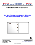
Refer to Figure 2-1. Successful problem diagnosis
requires the following approach to be applied to all
reported problems. There are seven basic steps to this
approach. These seven basic steps are the basis for the
PCM Drivability Checklist.
Basic Troubleshooting Approach
In this section we will look at a basic troubleshooting
approach and some service techniques for isolating
various engine systems from the boat systems.
Proper engine operation depends on numerous systems
and components functioning together. This of course,
makes any one system dependant upon the proper
operation of all the other systems.
When troubleshooting an electronic engine management
system it is necessary that:
1. Obtain a detailed description of the problem.
2. Check for Service Updates.
3. Perform a detailed visual inspection.
4. Verify the problem.
o
the Engine Mechanical Components,
5. Perform the On-Board Diagnostics
o
the Engine Fuel System Components,
6. Isolate and Repair the problem
o
the Engine Cooling System Components, and
7. Verify the problem has been corrected.
o
the Main Engine Electrical System Components
are all functioning as designed prior to troubleshooting
the engine management system. The PCM Drivability
Checklist is designed to help you ensure those
requirements are met.
Most engine management circuit failures cause stored
diagnostic trouble codes which have a diagnostic and
repair procedure designed to resolve the problem causing
the code. These codes identify specific failures and will be
resolved using the diagnostic manual. Isolating, analyzing
and resolving engine management failures is made even
easier using the PCM Drivability Checklist.
Diagnostic Trouble Codes (DTC) have assigned numbers
associated with each code. DTC 117 is ECT Sensor
Circuit Low Voltage.
The DTC’s also have both a Failure Mode Indicator (FMI)
and Suspect Parameter Number (SPN). Each DTC has
both a FMI and SPN in order to identify the exact circuit
failure.
NOTE: Diacom only displays the FMI and SPN numbers.
Be sure to have both these numbers for each fault
displayed.
NOTE: If you need training on connecting Diacom or
checking for trouble codes, refer to www.rinda.com/
training for some short “How-To” videos to assist you.
Failures which do not set trouble codes must be resolved
using the symptoms that are present. Some symptoms
are easily recognized such as “the engine overheated”.
Other symptoms can be vague because one person’s
description of hesitation may be another person’s stumble.
Basically, you are dealing with conditions where the
engine/boat package is no longer performing as it once
did. This may be relayed to you as a loss of rpm at wide
open throttle, or the boat doesn’t “feel” as strong as it once
did.
You probably use most of these steps every day when you
analyze a problem. Using the Drivability Checklist will help
you to remember to do all the steps, for every problem.
NOTE: Not all problems reported as engine problems
may actually be problems with the engine. Using the PCM
Drivability Checklist will help you distinguish between boat
and engine problems.
The PCM Drivability Checklist is a guide designed to give
you a list of items and procedures often overlooked when
troubleshooting a problem. Remember that the objective
is to repair the reported problem. The PCM Drivability
Checklist is especially useful for troubleshooting those
more difficult problems when it is unclear where the
problem may lie. Even for easily identified problems, such
as an overheat condition, the checklist can keep you from
overlooking or spending an unreasonable amount of time
on conditions known to PCM. Known problems will have
Service Updates issued to address problems such as
the overheat example cited above. Service Updates are
designed to quickly resolve and prevent a reoccurrence of
the problem.
In most cases, performing the PCM Drivability Checklist
will help you identify the problem so that you can repair
it. In those instances where you are unable to locate the
problem, the data you have collected on the completed
PCM Drivability Checklist will allow you to work with your
PCM Technical Service representative to more quickly
isolate and resolve the problem.
The PCM Drivability Checklist is based on seven basic
steps. Performing these steps, in the order provided, will
help you to isolate, identify and repair problems more
effectively.
L599003-13
10
PCM DRIVABILITY CHECKLIST - 2
BASIC TROUBLESHOOTING APPROACH
Obtain a clear concise description
of the problem
Check for applicable Service Updates
Perform a visual inspection of
the engine for obvious faults
Verify the Problem
Perform the On-Board-Diagnostic
(OBD) System Check
Isolate and Repair the Problem
Check/Clear Trouble Codes from ECM
Verify the Problem has been Corrected
Figure 2-1 Basic Troubleshooting Approach Tree
L599003-13
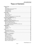
11
PCM DRIVABILITY CHECKLIST - 2
PCM DRIVABILITY CHECKLIST
ENGINE SERIAL NUMBER:
Date:
Dealership Name:
Technician’s Name:
Technician’s Contact Phone #:
Owner/Operator Name:
Person Reporting the problem (if different from owner/operator):
Service Writer or Person that took the problem report:
1) PROBLEM OR SYMPTOM:
:KR¿UVWREVHUYHGWKHV\PSWRP"
:KHQGLGWKHV\PSWRP¿UVWRFFXU"
$Q\UHFHQWFKDQJHRUVHUYLFHZRUNSULRUWRV\PSWRPRFFXUULQJUHSODFHGEHOWVRULPSHOOHUPDMRUHQJLQHRUERDWUHSDLUV
UHFHQWO\UHIXHOHGHWF"
+DVVRPHRQHRWKHUWKDQ\RXUVHOIWULHGWR
FRUUHFWWKHFXUUHQWV\PSWRP"
,I\HVZKDWZRUNZDVGRQH"
$FFHVVRULHV$GGHG5HFHQWO\"
,VWKHV\PSWRPFXUUHQWO\SUHVHQW"
6SHFLDOFRQGLWLRQVLIDQ\UHTXLUHGWRGXSOLFDWHWKHV\PSWRP
Use an additional sheet of paper if more space is required for symptoms or descriptions.
2) CHECK FOR SERVICE UPDATES:
ENGINE SERIAL NUMBER:
ENGINE MODEL NUMBER:
ENGINE HOURS:
HULL NUMBER:
ENGINE:
1RQH$SSO\
3HUIRUPHG
BOAT: 1RQH$SSO\
3HUIRUPHG
3) VISUAL INSPECTION:
Inspection
YES
NO
Inspection
YES
NO
(YLGHQFHRIRU([FHVVLYH:DWHU
LQWKH%LOJH
)OXLGOHYHOVFKHFNHG
/HDNLQJ)OXLGV
)LULQJRUGHUFRUUHFW
&RUUHFWVL]HSURSHOOHUVLQVWDOOHG
8QGHUZDWHUJHDULVXQGDPDJHG
$FFHVVRULHVDGGHG",I\HVFKHFNLWHPV
(YLGHQFHRIDQRYHUKHDW
(QJLQH+DUQHVVFRQQHFWRUV
FRQQHFWHGSURSHUO\
3K\VLFDO'DPDJHZLULQJFRQQHFWRUV
DVVHPEOLHVDQGRemove Spark Plugs
DQGLQVSHFWIRUÀXLGV
&RUURVLRQ
+XOOFOHDQDQGIUHHRIH[FHVVLYHJURZWK
4) VERIFY THE PROBLEM
YES
NO
Does the engine start and continue to go to 3 go to 1
run?
below below
1) Key-ON-Engine-OFF (KOEO)
YES
NO
Fuel Press.
%RWK)XHO3XPSVUXQVHFRQGV
)XHO3UHVVXUHQHDUZRWVSHFL¿FDWLRQ
ZKHQSXPSVUXQ
2) Key-ON-Engine-Running (KOER)
YES
NO
Fuel Press.
YES
JRWR:DWHU7HVW
NO
Fuel Press.
(QJLQHFUDQNV
)XHO3UHVVXUHQHDUZRWVSHFL¿FDWLRQ
HQJLQHFUDQNLQJ
(QJLQH6WDUWVDQGFRQWLQXHVWRUXQ
3) WATER TEST
9HULI\UHSRUWHGV\PSWRP
)XHO3UHVVXUHLGOH
)XHO3UHVVXUHXQGHUORDG#:27
Check Accessories Added:
+HDWHU
6KRZHU
+RW:DWHU7DQN
)OXVK.LW
0XOWL)XQFWLRQ'LVSOD\
6\QFKURQL]HU
$IWHU0DUNHW6WHUHR(TXLSPHQW
$IWHU0DUNHW'HSWK)LVK)LQGHU
$IWHU0DUNHW1DYLJDWLRQDO(TXLSPHQW
VXFKDV*365DGDU6RQDU$XWRSLORW
V\VWHPV
$IWHU0DUNHW5DGLR(TXLSPHQW
/LJKWV
2WKHUSOHDVHOLVW
4A) Revised or additional symptom found?:
1
Figure 2-2 Drivability Checklist
L599003-13
12
PCM DRIVABILITY CHECKLIST - 2
PCM DRIVABILITY CHECKLIST
5) PERFORM THE OBD SYSTEM CHECK
&2'(635(6(17
Continue to Step 6
',$*1267,&352&('85(86('
6) ISOLATE AND REPAIR THE PROBLEM.
:HUH\RXDEOHWRLVRODWHDQGUHSDLUWKHSUREOHP",IYESFRQWLQXHWRStep 7.
,INOFRPSOHWHWKH'ULYDELOLW\&KHFNOLVWIRU1R&RGHVVWHS$EHORZ,IWKHSUREOHPLVVWLOOQRWUHVROYHGWKHQFDOOIRU
IDFWRU\WHFKQLFDODVVLVWDQFH
6A) NO CODES - ENGINE RUNS - DRIVABILITY SYMPTOM STILL PRESENT
Inspection or Check
YES
NO
Inspection or Check
5HYLHZ6WHSV1WKUX5
,QVSHFWIXHOIRUFRQWDPLQDWLRQ
(OHFWULFDOO\LVRODWHHQJLQHIURPERDW
3RZHUWUDLQLVDOLJQHG
5HPRYHDQG,QVSHFW'LVWULEXWRU&DS
DQG5RWRU/RQO\
&KHFNrecord,JQLWLRQZLUHUHVLVWDQFH
5HPRYHDQG,QVSHFWHDFKVSDUNSOXJ
3HUIRUPD&RPSUHVVLRQ&KHFN
RQDOOF\OLQGHUVRecord below.
YES
NO
WATER TEST
9HULI\&$05HWDUG**/RQO\
3HUIRUPDQFHYHUL¿HGDJDLQVWD
VLPLODUERDWZVDPHHQJLQH
SDFNDJHLIDYDLODEOH
3HUIRUPWKH'LDFRP3RZHU%DODQFH
&KHFNXQGHUORDG#USP
3HUIRUPWKHKDUQHVVµ:LJJOH7HVW
'LDFRPUHFRUGLQJ3UH'HOLYHU\WHVW
7) VERIFY REPAIR HAS CORRECTED THE PROBLEM. &KHFNIRUDQGFOHDUDOOFRGHVIURPWKH(&0PHPRU\
Water test the boat.5XQWKHHQJLQHIRUDPLQLPXPRIWZRPLQXWHVWKHQYHULI\WKDWQRFRGHVKDYHUHWXUQHG
&RQWLQXHZLWK\RXUZDWHUWHVWORQJHQRXJKWRYHULI\WKDWWKHSUREOHPKDVEHHQFRUUHFWHG
** CAM Retard - ‘02 thru ‘06 = 43-47 degrees
‘07 - SN 485993 = 0 - 4 degrees/CES and SN 485994 = 15 + 2 degrees
FRONT
COMPRESSION
PRESSURE:
1
2
Ohms
3
4
Ohms
Ohms
5
6
Ohms
Ohms
7
8
Ohms
psi
1
2
psi
psi
3
4
psi
psi
5
6
psi
7
8
6.0L - 130-215 psi
6.2L - 130-215 psi
Lowest pressure
should be within 70%
of highest pressure.
Minimum cylinder
pressure - 100 psi.
psi
psi
FLYWHEEL END OF ENGINE
ALL V-8 MODELS
COMPRESSION CHECK
5.0 / 5.7 Liter
LH ROTATION
1
2
3
4
3
4
3
4
5
6
5
6
5
6
7
8
7
8
7
8
Rotation
PCM Premier Dealer Website - All the Latest
Publications
1
4
5
3
2
8
7
6
NO
DISTRIBUTOR
c
c
5
6
3
3
5
4
5
7
3
2
4
7
1
1
L510016 - 6.0L Engine Mechanical Service Manual
1
8
2
2
8
1
L510030 - GCP / 4G Diagnostic Service Manual
L510015 - 5.0/5.7L Engine Mechanical Service Manual
FRONT
2
8
0DVWHU(QJLQH6SHFL¿FDWLRQ6KHHWV
FRONT
1
2
REFERENCES:
6.0 / 6.2 Liter
LH ROTATION
7
IGNITION WIRE RESISTANCE CHECK
Less than 10,000 ohms/ft
5.7 Liter
RH ROTATION
FRONT
6
FLYWHEEL END OF ENGINE
ALL V-8 MODELS
4
Ohms
5.0/5.7L - 130-215 psi
6
Ohms
FRONT
Rotation
FLYWHEEL END OF ENGINE
ALL V-8 MODELS
FIRING ORDER:
1-8-4-3-6-5-7-2
FIRING ORDER:
1-2-7-5-6-3-4-8
FIRING ORDER:
1-8-7-2-6-5-4-3
Figure 2-2 Drivability Checklist
L599003-13
13
PCM DRIVABILITY CHECKLIST - 2
Using the PCM Drivability Checklist will help you to
remember to do all the steps for every problem.
Service Updates must be performed prior to proceeding
with any troubleshooting procedure.
The PCM Drivability Checklist
Record your engine serial number, model number and
engine hours on the PCM Drivability Checklist. This
information is necessary to locate applicable Service
Updates. With very little time and effort, the reported
symptom may be identified as an issue that a Service
Update corrects. Always check for Service Updates before
proceeding.
The following seven checks are the basis for the PCM
Drivability Checklist, Figure 2-2. The seven steps of the
Basic Troubleshooting Approach can be applied to every
problem that you encounter.
1. Obtain a clear, concise description of the problem.
Whenever possible, interview the owner/operator and
understand any conditions leading up to, and during,
the problem occurring. Understanding if recent service
has been performed, or a recent abnormal event has
happened, can greatly aid you in your troubleshooting
effort.
Often, an owner/operator provides only information about
the symptom that is currently present. Find out if any
recent work was performed on the engine, such as a
broken belt or failed raw water pump impeller.
• Has someone already tried to correct the current
problem?
• Have any new accessories been added lately?
• Did the problem occur shortly after the last time
he refueled?
• Did the problem occur after a recent repair such
as a hull repair where the underwater gear was
replaced?
As you can see, there are numerous questions that could
be asked based on the symptom and the owner/operator’s
responses. Some of the more important questions to ask
are detailed on the PCM Drivability Checklist, Figure 2-2,
Step 1.
Based on the symptom you receive from the owner/
operator, you may already know where to begin your
troubleshooting. Many symptoms provide you that quick
and easy insight to the problem. Some examples would
be:
1. Over or Under Temperature problems –
Troubleshoot the Cooling System
2. Various electrical issues such as no or slow
cranking, dead battery, low or high voltage
reading at the dash, etc. – Troubleshoot the
Main Electrical System.
Go to your PCM Premier Dealer website to search
applicable Service Updates.
3. Perform a visual inspection of the engine for
obvious faults. One of the most important, yet least
performed, functions when troubleshooting is a detailed
visual inspection. Always visually and physically inspect
the engine wiring harness for damage caused by
misrouting, chaffing, pinched wires or excessive heat.
Check suspect connections for any that may be loose or
broken. Inspect terminals for corrosion or being properly
seated into connector.
Pay close attention to the power and ground connections
for corrosion and/or accessory devices added in.
Improperly added accessories can adversely affect engine
operation. Inspect the engine and its assemblies for
signs of damage or failure. Visually inspect for signs of
arcing, fluid leaks, excessive water in the bilge, cracked or
damaged assemblies and signs of excessive heat such as
melted or deformed parts and discolored paint.
When you perform a visual inspection you are looking
for obvious conditions that could cause the reported
symptom. If an overheat is reported you look for
discolored paint and other heat related damage. When
you have a performance issue reported; include the often
overlooked inspections of the boat, for conditions that
may affect performance such as hull damage or growth,
damaged underwater gear and if the correct propeller is
installed.
Referring to the PCM Drivability Checklist, you can
see there are a number of inspections listed, such as
discolored paint from excessive heat, fluid leaks, fluid
levels, etc. Most of the inspections listed are items easily
seen as faults. When you have a performance issue, be
sure to include in your inspection a check of the ignition
wires and spark plugs to include:
1. Proper routing,
3. Malfunction Indicator Lamp (MIL) or Check
Gauges Lamp (CGL) is illuminated on the
dash – troubleshoot the engine management
system.
NOTE: The MIL or CGL normally lights when the ECM
stores a trouble code. Some boat manufacturers utilize a
digital dash display to indicate these faults. Check your
boat owners manual for each application.
Remember to closely follow the PCM Drivability Checklist
so a problem, or cause of a problem, is not overlooked.
2. Correct firing order, and
3. Inspect spark plugs for broken or cracked
insulators.
Be alert as you perform the visual inspection. You may
repair the reported problem by reconnecting a wiring
connector, or cleaning the corrosion away from the power
and ground terminals of the battery.
Samples of some observations that would need attention
before attempting to run the engine are:
2. Check for applicable Service Updates. Before
you begin work on an engine, always check for Service
Updates that may apply to the engine being serviced.
L599003-13
14
PCM DRIVABILITY CHECKLIST - 2
1. Melted, skinned or burnt wiring – You will
need to repair the wiring. The condition of the
wiring may have been caused by a Cooling
System failure or a Main Electrical System
failure.
2. Oil level excessively high on the dipstick
– This may indicate a foreign liquid in the oil
or an over-fill condition exists. Investigate
and correct a high oil level condition before
proceeding. Symptoms of too much oil in the
crankcase include a loss of power, a loss of top
end rpm, a possible low oil pressure reading
and the engine may be going into Power
Derate Mode.
3. Evidence of excessive water in the bilge – A
rust/water line on the starter/engine block is
usually a good indication; if the water is not
still covering these items. Multiple electrical
issues may remain. Most common is a failed
starter. High water may short out the battery
and other electrical devices. As mentioned
above, you may have water in the engine oil or
transmission.
The results of a good visual inspection will help you
determine where you will concentrate your troubleshooting
efforts.
4. Verify the problem. At this point you must verify the
problem or symptom you are trying to repair. In order to
verify the problem, you will need to connect your Diacom
scan tool and Fuel Pressure gauge to the engine. You
should also have your Digital Multi-Meter (DMM) available.
We want to perform some basic checks before we go for a
water test and verify the problem. You are going to need
your senses: sight, hearing and touch, as much as you will
need your tools. A Digital Multi-Meter (DMM), Diacom and
Fuel Pressure Gauge will be used while performing these
checks. This will be your first look at the various engine
systems, with a focus on troubleshooting the problem.
Within a few minutes of testing you may know the direction
of your troubleshooting efforts.
Try to start the engine. If the engine starts and continues
to run, you would go to the Water Test and verify:
1. The reported problem and
2. The fuel pressure at wide-open-throttle.
If we have a no crank condition we would troubleshoot the
Main Electrical System and the Starter circuit.
For any other conditions, long crank, hard start, stalling,
etc., we want to continue with our testing and perform the
Key-On-Engine-Off (KOEO) test.
Key-On-Engine-Off (KOEO) Test. This test may be used
to determine the condition of the engine’s Electrical, Fuel
and Engine Management systems:
Place the ignition switch in the Key-ON-Engine-OFF
(KOEO) position. Ensure the boat’s safety lanyard is
properly connected. You should listen, feel and observe
that the following actions take place:
1. Both fuel pumps run for 2-4 seconds. Listen for
each pump and place your hand on each pump
to verify that it is indeed running. Diacom can
be used to cycle the fuel pumps as necessary.
NOTE: You can unplug the low pressure fuel pump
(mounted to outside of FCC) electrical connector and
cycle the ignition to listen and feel whether the high
pressure fuel pump (located inside FCC) runs.
Always verify, for yourself, that the problem you are
about to troubleshoot is the same problem reported to
you in Step 1 of the PCM Drivability Checklist. Verifying
the problem may require you to water test the boat and
trying to recreate the conditions under which the failure
occurred.
Refer to Figure 2-2, Step 4. Step 4 is a series of checks
leading up to verifying the reported problem. Remember
that the PCM Drivability Checklist is to be used to help you
locate a problem.
Refer to the Troubleshooting Tree for Step 4 of PCM
Drivability Checklist, Figure 2-3. This diagram will take
you through a step by step approach to troubleshoot and
repair the problem.
2. Observe the Fuel Pressure Gauge; fuel
pressure should rise to the proper specification
while the fuel pumps run.
You have learned a lot about the engine systems when
you turned the ignition ON. The simple action of turning
the key to the ON position has allowed you to check
three engine systems simultaneously - Electrical, Fuel
and Engine Management. If the actions described in the
previous frame occur, then you have verified the:
1. Boat’s Ignition Switch,
Refer to Figure 2-3. This diagram is a troubleshooting
tree for Step 4 of PCM Drivability Checklist. As you can
see from Figure 2-3, if an action performed fails you may
have a new branch to follow to troubleshoot and repair the
problem.
NOTE: For illustrative purposes each test presumes the
problem has not been resolved. Therefore, you proceed
to the next step. In actual troubleshooting, if any step
corrects the problem, there would be no reason to proceed
further. You would verify your repair, Step 7 of the PCM
Drivability Checklist.
L599003-13
15
2. Boat’s Safety Lanyard circuit,
3. Low and High Pressure Fuel pumps,
4. Relays - System and Fuel Pump,
5. Fuse Block fuses and 100A Fuse,
6. ECM powered up and functioned to turn on the
fuel pumps,
7. Battery voltage is at least 9.6 vdc, and
8. Power and ground circuits and related
components are functioning.
PCM DRIVABILITY CHECKLIST - 2
1. Main Electrical System – All of the Starter
Circuits to include the starter relay,
transmission neutral safety switch, starter,
the associated power and grounds, the boat’s
ignition and safety lanyard circuits, and the
Battery meets the minimum system voltage
requirements.
NOTE: ECM will not power up if the battery voltage is
less than 9.6 vdc.
NOTE: If the actions described do not occur, verify the
shift lever is in neutral. Verify the battery voltage, system
power and ground connections starting at the battery.
If the previously mentioned actions do not take place,
you can see on Figure 2-3 that you would move to a
new branch of the troubleshooting tree. Here you will be
troubleshooting the fuel pumps for a no run condition, or
fuel pressure for an abnormal condition.
Each step or action you take will help resolve the problem
that is present. If the pumps run and the fuel pressure
rises, the next step is the Key-ON-Engine-Running
(KOER) test.
Key-ON-Engine-Running (KOER) Test. Do Not turn the
key to “OFF” between the Key-ON-Engine-OFF test and
this test. Place the ignition switch in the START position
to crank, or roll over, the engine. You should observe the
following actions:
Warning: Most engines utilize an “auto-crank”
feature. This feature allows the engine to crank up to 5
seconds, or until the engine starts.
2. Engine Management System – IF the fuel
pumps run for 2-4 seconds after the engine
stops cranking, the Crank Sensor signal is
presumed to be present at the ECM enabling
the ignition circuits and Fuel System.
Typically, at this point the engine will be running.
NOTE: If the actions described do not occur, verify the
shift lever is in ‘neutral’. Verify the battery voltage, system
power and ground connections starting at the battery
At this point in our test process, typically, we know the
engine will start and run. Complete Step 4 of the PCM
Drivability Checklist by water testing the boat. During the
Water Test, you will be verifying two things:
1. The reported problem from Step 1 is or is not
present.
1. The engine cranks or rolls over for at least 5
seconds,
2. The Fuel Pressure Gauge reading should rise
to the same level observed during the Key-OnEngine-Off test. Fuel pressure rising is your
indication that the fuel pumps are running.
3. The engine starts and continues to run.
4. If the engine does not start, the fuel pumps
should run for 2-4 seconds after engine stops
cranking. If the fuel pumps do not run for 2-4
seconds after the engine stops cranking,
the ECM did not turn the pumps on. Perform
the On-Board Diagnostic System Check to
troubleshoot this problem.
NOTE: Turning the key to the ‘START’ position resets the
ECM which will enable the fuel pumps for 2-4 seconds for
prime. If the engine is failing to start, be sure to crank the
engine for a minimum of 5 seconds. You are checking
to see if the ECM is receiving the Crankshaft Position
Sensor (CKP) signal which enables the fuel and ignition
circuits. It is the CKP signal that causes the pumps to run
for 2-4 seconds after you stop cranking the engine. For
troubleshooting, utilize the Diacom scan tool to observe
Battery Voltage, Engine Speed and Fuel Pump Output
status while the engine cranks.
2. The fuel pressure under load, at WideOpen-Throttle (WOT), remains at the proper
specification.
Remember it is absolutely essential to verify fuel pressure
under load, at wide-open-throttle. This is the only reading
that verifies the integrity of the fuel system.
Refer to Figure 2-3. You can see that if an action failed we
continue to another branch on the trouble tree.
If the engine cranks normally, but still fails to start,
continue to Step 5, the On-Board Diagnostic (OBD)
System Check of the PCM Drivability Checklist. The OBD
System Check will guide you to the appropriate diagnostic
procedure for no start and hard start conditions.
NOTE: Normal starter cranking RPM is 150-200 RPM.
This can be observed on the Diacom display. If normal
cranking RPM is not achieved, troubleshoot the starter for
a slow crank condition.
Your action of turning the key “ON” then to the “START”
position has allowed you to verify more of the operational
capability of the three engine systems - Electrical, Fuel
and Engine Management. The additional circuit and
component functions verified are:
L599003-13
16
PCM DRIVABILITY CHECKLIST - 2
STEP 4
- VERIFY THE PROBLEM IMPORTANT:
YES
FOR REPORTED MAIN ELECTRICAL SYSTEM
PROBLEMS SUCH AS STARTER OR CHARGE
SYSTEM PROBLEMS - STOP!
PERFORM MAIN ELECTRICAL SYSTEM
TROUBLESHOOTING FIRST.
START THE ENGINE
Does the engine start and run?
NO START
4-1
Key-ON-Engine-OFF
Do Both Fuel Pumps Run 2-4 Seconds
then turn off?
NO
Refer to the KOEO - Pump(s) Do Not Run Troubleshooting Tree
YES
Is fuel pressure within
specification while fuel pumps run?
Refer to the Fuel
Pressure-Out-Of-Range
Troubleshooting Tree
NO
YES
4-2 Key-ON-Engine-Running
Refer to the
Starter Circuit
Troubleshooting Tree
Does the engine crank over NO
for 5 seconds if the
engine does not start?
YES
Does fuel pressure rise near specification while
engine cranks, and fuel pumps run 2-4 seconds
after the engine stops cranking if engine
does not start?
NO
Perform the OBD
System Check
YES
Does the engine start and continue
to run?
NO
Perform the OBD
System Check
YES
4-3
WATER TEST
Verify the Owner
reported problem.
Is fuel pressure within specification
under load @ W.O.T.
NO
YES
STEP 5 - OBD SYSTEM CHECK
Figure 2-3 Verify the Problem
L599003-13
17
Refer to the Fuel
Pressure-Out-Of-Range
Troubleshooting Tree
PCM DRIVABILITY CHECKLIST - 2
5. Perform the On-Board-Diagnostic (OBD) System
Check. The On Board Diagnostic (OBD) System Check
is an organized approach to identifying a problem created
by an electronic engine control system malfunction. This
check verifies the following:
1. The ECM power and ground circuits.
2. The ECM can communicate with the scan tool.
3. The ECM will allow the engine to start and
continue to run.
4. The ECM has or has not stored Diagnostic
Trouble Codes (DTC).
If DTC’s are present, the OBD System Check will direct
you to the next procedure you need to perform.
Details of the OBD System Check will be covered in the
Engine Management section of this course. The OBD
System Check will direct you to additional diagnostic
procedures based on the results of each step.
6. Isolate and Repair the Problem. Utilize your
resources. Obtain the Diagnostic manual for the problem
you have encountered. Follow the procedures exactly
as they are written. Do Not skip any steps. If you have
reached a point in your testing where you have:
1. Checked all the components in a system,
2. Properly completed the PCM Drivability
Checklist procedures through Step 5,
3. Completed Step 5 and did not find codes, or
found and corrected code related problems but
the symptom is still present,
4. An engine that starts and runs but still exhibits
a symptom, and
5. Not resolved the problem.
You need to STOP and refer Figure 2-2 of the PCM
Drivability Checklist, Step 6A. Step 6A is designed to
check for a variety of problems known to affect drivability.
Refer to Figure 2-4, The Drivability Checklist - No Codes
Troubleshooting Tree, for Step 6A of the PCM Drivability
Checklist, Figure 2-2. This troubleshooting tree follows
the items listed under Step 6A on the PCM Drivability
Checklist.
Step 6A-1 is to review the data collected as you performed
the first 5 steps of the checklist.
1. Review the symptom information the owner/
operator provided when you questioned him/
her on recent events or service.
2. Recheck the engine model and serial number.
3. Recheck the Service Updates.
4. Review your visual inspection.
5. Recheck for accessories added.
6. Review Step 4 “Verify The Problem”.
7. Run another check for diagnostic trouble
codes.
If a problem is found, correct that problem before
proceeding. If you skipped any portion of the first 5
steps go back and perform those checks or inspections.
After you verify that all steps, 1-5, have been properly
completed, and the results properly analyzed, proceed to
Step 6A-2.
Step 6A-2 - An extremely important test is to verify the
quality of the fuel in the boat. Sample the gasoline for
water, diesel fuel and/or other contaminants. This can
be done by draining the FCC fuel bowl into an approved
container for inspection.
If you suspect fuel system contamination, connect your
auxiliary fuel tank to the engine, drain the FCC and retest
the boat. If performance returns to normal, you know
you have a fuel quality and/or fuel availability problem.
This test analyzes two problems; fuel quality and fuel
availability at the same time. Be careful not to misinterpret
the results.
Important: Caution must be taken when using the remote
fuel tank. The tank must be properly strapped down. The
lines and fittings must be secure and away from heat and
moving components.
Remember that proper fuel pressure verifies the
components of the fuel system, not the quality of the fuel.
Always inspect for fuel quality and utilize your auxiliary fuel
tank to confirm your findings.
Step 6A-3 - Improper powertrain alignment may affect
boat and engine performance. The powertrain cannot be
properly aligned if there is damage to the strut or shaft.
When you performed the Visual Inspection, Step 3 of the
PCM Drivability Checklist, you should have inspected the
boat for damage that may cause a loss of engine or boat
performance. If you did not perform those inspections do
so before performing this step.
Steps 6A-4 – 6A-8 are a series of inspections involving the
ignition circuits.
Step 6A-4 - On 5.0/5.7L engines only, remove the
distributor cap and inspect the cap and rotor for abnormal
conditions.
Step 6A-5 - Check and record the resistance of each spark
plug wire. Ignition wire resistance should not be greater
than 10,000 ohms per foot. Record the results in the space
provided on the PCM Drivability Checklist, Figure 2-2.
Leave the plug wires disconnected.
Step 6A-6 - Remove each spark plug and inspect for
abnormal conditions such as: wrong type, size, reach
or heat range of the spark plug installed, improper gap,
fouling or physical damage.
Step 6A-7 - With all eight spark plugs removed, perform a
compression check on all 8 cylinders. Record the results of
the compression check in the space provided on the PCM
Drivability Checklist. Re-install the spark plugs and ensure
the ignition wires are all connected and routed properly.
L599003-13
18
PCM DRIVABILITY CHECKLIST - 2
Step 6A-8 (5.0L/5.7L Engines Only) - Using your Diacom
scan tool with the engine running at idle, verify CAM
Retard is within specifications. Adjust as required to set to
the proper specification.
Completing the steps on your PCM Drivability Checklist
through step 6A will locate most symptomatic problems.
Be sure to record all your findings as you perform the PCM
Drivability Checklist.
Refer to Steps 6A-9 – 6A-12 - The final series of checks
will be made with the boat in the water.
If you have completed the PCM Drivability Checklist
through Step 6A, and have not found and resolved the
problem, STOP and call the PCM Technical Service
Department for assistance. PCM Warranty and Service
Department: 803-345-0050.
Step 6A-9 - Whenever practical, if another boat of similar
size, with the same engine package is available, use it to
verify and compare engine parameters for performance
issues.
Step 6A-10 - Perform a Power Balance Test on the engine.
The Power Balance Test is accessed using your Diacom
scan tool. For best results, perform this test with the
engine under load, running between 1600 - 1800 RPMs.
This test can isolate a coil/ignition module circuit and/or
fuel injector circuit problem to a specific cylinder. This will
help determine what cylinder(s) to focus your diagnostic
efforts on.
Have your completed PCM Drivability Checklist and
Diacom recording readily available when you call the PCM
Technical Service Department for assistance. You may
be requested to fax or e-mail a copy of the checklist to the
Technical Service Department during your discussion with
the factory service representative.
NOTE: The Diacom Power Balance Test should be
performed with the engine under load. This provides
for easier viewing and pitch change recognition when a
cylinder is shut off. The Diacom Power Balance Test will
be discussed in detail in the PCM Engine Management
System Section, under Diacom Tests.
Step 6A-11- Perform the engine harness “Wiggle Test”.
With the engine running, start at the boat/engine harness
connectors and wiggle the harness. Move forward along
the starboard side wiggling the harness at sensor, injector
and coil connections. Then repeat for the port side of the
harness. A change in engine operation indicates a wiring
defect in the area where the wires were wiggled. Repair
wiring or connections as required.
Warning: Take ALL Safety Precautions into
consideration since you will be working around a HOT
running engine with moving components.
Step 6A-12 - The final test will be a Diacom recording
based on the Pre-Delivery test run. Compare this Diacom
file to the Pre-Delivery recording of this engine if available,
or to another new engine of the same model. Look for data
that is out of range versus new engine data. Troubleshoot
and repair circuits that read out of range. File this test and
all relative information in the customer’s service and/or
sales file.
NOTE: Keep your Diacom recording so that it may be
emailed to the factory service representative if you are
unable to resolve the problem.
L599003-13
19
PCM DRIVABILITY CHECKLIST - 2
DRIVABILITY CHECKLIST - NO CODES
Inspect or correct recent
service work performed.
6A-1
Review the results of Steps
1-5
6A-2
Inspect fuel for contamination water, correct fuel type, ect.
Correct fuel/fuel system
as necessary.
6A-3
Verify powertrain
alignment.
Correct alignment
as required.
6A-4
Remove and Inspect the
Distributor Cap and Rotor.
(5.0/5.7L Only)
Replace Cap and
Rotor as necessary.
6A-5
Ignition Wire Resistance check
Record results.
Replace spark plug
wires as necessary.
6A-6
Remove and Inspect each spark
plug for damage or abnormal
condition.
Replace spark plugs
as necessary.
6A-7
Perform a Compression Check
on all 8 cylinders and record.
Refer to the Engine
Mechanical Service
Manual.
WATER TEST
6A-8
6A-9
Verify
Cam Retard (5.0/5.7L only)
Adjust as required.
Performance verified against
Same
a simialr boat w/same
engine package
6A-10
Perform the Diacom
Power Balance Test.
6A-11
Perform the harness
Wiggle Test.
6A-12
Pre-Delivery Diacom
recording.
Normal operation.
Refer to the
Diagnostic Manual
Isolate and repair wiring
or connector problems.
Isolate and repair circuits
outside of normal parameters.
Figure 2-4 PCM Drivability Checklist - No Codes
L599003-13
20
PCM DRIVABILITY CHECKLIST - 2
7. Verify your repair action has corrected the problem.
Once you have completed a repair action, clear any codes
from the ECM. If codes return after repairs are made or
you had multiple codes listed in the ECM’s memory return
to Step 6, Isolate and Repair the Problem, and perform
the procedure and repair action for the remaining code(s).
Steps 6 and 7 will have to be performed for each stored
code until the system is repaired and tests normally.
Always retest to verify the engine is operating normally.
The original problem may have been caused by another
system or event; ensure that you have corrected both the
cause and the original problem. When you verify your
repair action, be sure to test With the boat in the water,
and:
1)
Run the boat a minimum of two (2) minutes to
verify that no codes reset, and then
2)
Run the boat long enough to verify your repair has
corrected the problem.
L599003-13
21
PCM DRIVABILITY CHECKLIST - 2
SYSTEM POWER CHECK
Key-OFF
Verify that the battery is the correct size,
rating, and fully charged. Battery charge
needs to be verified using a load tester.
Replace Battery with a
known good battery of
the correct size and rating.
Inspect, clean, and repair as
required battery terminals and
connections.
Inspect, clean, and repair as
required engine ground
connections.
NOTE: Ground locations are critical
for proper engine operation. Refer
to the Main System Power - Grounds
Diagram for device and ground
locations. Ensure only the ECM is
grounded at the Port ground stud.
Key ‘ON’ and boat lights ON. Verify
voltage is not less than .3 vdc of battery
voltage at each system power test point.
Refer to Main System Power Test Points Diagram.
Inspect, clean and repair connections
or wiring that are not within
specification.
Continue to Starter Circuit, Charge Circuit
or return to the diagnostic procedure
that requested a System Power Check.
Figure 2-5 System Power Troubleshooting Tree
L599003-13
22
PCM DRIVABILITY CHECKLIST - 2
STARTER CIRCUIT
TROUBLESHOOTING TREE
Reported symptom is a
Slow or No Crank condition.
From Step 3 of the
PCM Drivability Checklist
When you perform the Visual Inspection
include the Starter Circuit, exhaust system
to include physical damage, missing
exhaust flaps, and exhaust restrictions.
Remove all 8 spark plugs and inspect for
evidence of fluid in the cylinders.
Ensure the shift lever is in Neutral position.
Was fluid found in cylinders
and/or on the spark plugs?
Dry
Correct conditions with the
exhaust system. Continue with
Starter Circuit trouble tree and
verify starter opration.
Verify System Power
Wet
Check for Diagnostic
Trouble Codes.
No Codes
Codes Present
Perform Diagnostic Procedure
for the Code(s) present.
Water/Coolant
Present
Fuel Present
Perform diagnostics for
system running rich, or
possible fuel injector
stuck open.
Pressure check exhaust
manifolds and elbows for
leaks.
Replace faulty exhaust
manifold or elbow, if goodTroubleshoot and repair
engine mechanical.
Once the condition that allowed
fluid into the cylinders is repaired.
Disable fuel and spark by
removing the System Relay.
Perform a compression check on
all 8 cylinders to verify no other
engine damage is present. Return
to ‘Verify System Power’ step on
the Starter Circuit Trouble Tree
and verify starter operation.
Disable fuel and spark by
removing the System Relay.
Key Switch to ‘START’ position
Normal
Perform a compression
check on all 8 cylinders.
Fail
Re-Install spark plugs
No Crank
Re-Install spark plugs
Pass
Re-Install spark plugs
Troubleshoot and repair
engine mechanical
problem.
Slow Crank
Go To
Slow Crank
Trouble Tree
Normal
Operation
Re-Install
System Relay
Figure 2-6 Starter Circuit Troubleshooting Tree
L599003-13
23
Go To
No Crank
Trouble Tree
PCM DRIVABILITY CHECKLIST - 2
STARTER CIRCUIT
TROUBLESHOOTING TREE
SLOW CRANK CONDITION
Slow Crank
Using a Clamp Meter, clamp the
meter on the positive battery
cable connected to the starter.
Set the meter for DC Amperage
reading. Turn the key to START.
Observe meter reading.
Are readings within range listed?
Typical 5.0/5.7L - 150-250 A
Typical 6.0/8.1L - 210-325 A
NO
Replace Starter.
YES
Verify repair.
Positive Battery Cable Check.
Connect the DMM (+) lead to the
+ battery post. Connect the
DMM (-) lead to the Starter
battery terminal. Turn the
key to START and observe the
DMM reading is less than . 6 vdc.
YES
Normal
YES
Normal
NO
Replace negative battery cable
with one of the correct gauge
and length.
Verify Repair
Normal
Operation
NO
Check both cables
Negative Battery Cable Check.
Connect DMM (-) to the - battery
post. Connect DMM (+) to the
starboard engine block ground
stud. Turn the Key switch to
START and observe your DMM for
a reading less than .2 vdc.
YES
NO
Troubleshoot positive cable back
to the battery. Ensure that devices
such as a Battery Switch are
connected and functioning properly.
Verify the positive cable is the same
gauge from the starter to the battery.
Replace undersized cable with the
correct size. Repair or replace
postive cable with one of the
correct gauge and length.
Verify Repair
****** IMPORTANT ******
When you have completed your troubleshooting and
repair of the starter, be sure to Reinstall the System
Relay, then verify the engine starts and runs.
Figure 2-7 Starter Circuit - Slow Crank
L599003-13
24
PCM DRIVABILITY CHECKLIST - 2
STARTER CIRCUIT
TROUBLESHOOTING TREE
NO CRANK CONDITION
No Crank
Connect a Remote Starter Switch
between the Starter’s Battery and ‘S’
terminals. Momentarily engage the switch.
No Crank
Replace Starter.
Verify repair.
Cranks
Verify Transmission Neutral
Safety Switch operation.
Adjust shift linkage or Replace
Transmission Neutral Safety
Switch, as necessary.
Disconnect the 2-pin Boat Harness connector. NO
Is battery voltage present at pin “1” of the
connector?
Troubleshoot and repair loss
of system power at pin “1”.
YES
Momentarily jumper engine 2-pin connector
pin “1” to 8-pin connector pin “7”.
Does the engine crank?
NO
Remove Starter Relay.
Jumper engine 2-pin connector
pin “1” to 8-pin connector pin “5”.
Is battery voltage present between
relay socket pins 85 (-) and 86 (+)?
YES
Repair boat wiring.
Verify repair.
YES
NO
Verify relay socket pin 85 path to
ground. The ground path goes
through the neutral safety switch
to the ECM. Repair as necessary.
Verify relay socket pin 86
path to 8-pin connector
pin “5”. Repair as necessary.
Verify battery voltage is present
at pin 30 of the starter relay socket.
Troubleshoot and repair power to
pin 30 as required. Verify repair.
Momentarily jumper relay
socket pin 30 to 87.
Cranks
Replace Starter Relay.
Verify Repair.
No Crank
Verify Repair
Verify and repair wire between
relay socket pin 87 and ‘S’ terminal
of the Starter. Verify repair.
****** IMPORTANT ******
When you have completed your troubleshooting and
repair of the starter, be sure to Reinstall the System
Relay, then verify the engine starts and runs.
Figure 2-8 Starter Circuit - No Crank
L599003-13
25
Step 1
L599003-13
26
NO
Repair connection
between fuse and pin 30.
Repair harness between fuel
pump and Fuel Pump Relay
socket. Verify repair.
NO
YES
Step 3
*
Figure 2-9 Fuel System - Fuel Pump(s) Do Not Run
KOEO - Verify battery voltage at both
ECM “battery feed” connector pins.
Verify continuity between relay
socket pin “85” and ECM “fuel pump
relay control” pin. Repair circuit and
retest. If circuits and connections are
good, replace ECM. Verify repair.
NO
*
Unplug ECM connector.
YES
Step 5
Replace Fuel Pump
Relay. Verify repair.
Connect a test light between
pin 30 and 85. Cycle fuel pumps.
Does test light illuminate for
2-4 seconds?
YES
Step 4
Refer to the Diagnostic Manual,
Section 1, for Specifications on
the test lamp used. Refer to
Section 2 and 5 for handling
instructions and connector
locations for the ECM.
Section 3 of the Diagnostic
Manual contains a description
and service instructions for the
Fuel System Components.
Jumper relay socket pin 30 to
87. Do both fuel pumps run?
YES
Verify and repair
connections between
fuel pump and harness
connector. If good,
replace fuel pump.
Verify repair.
Verify battery voltage at
fuel pump connector.
NO
Step 2
*
KEY-ON-ENGINE-OFF
- PUMP(S) DON’T RUN TROUBLESHOOTING TREE
YES
Remove Fuel Pump Relay.
Is battery voltage present
at fuel pump relay socket
pin “30”?
KOEO - verify battery voltage
across the three system fuses.
No Codes
NO
Verify and replace defective fuse and retest.
If fuse blows again troubleshoot and repair short in
the circuit the fuse protects. Verify repair.
Perform Diagnostic Procedure
for the Code(s) present.
Codes Present
Perform the On-Board-Diagnostic
(OBD) System Check
Key-ON-Engine-OFF
Do Both Fuel Pumps Run 2-4 Seconds
Then turn off?
NO
PCM DRIVABILITY CHECKLIST - 2
PCM DRIVABILITY CHECKLIST - 2
KEY-ON-ENGINE-OFF
FUEL PRESSURE OUT OF RANGE - PUMPS RUN
Below Specification
Above Specification
Verify LPFP output volume.
Connect an auxiliary fuel tank
between the LPFP (inlet) and FCC
(return).
Low Pressure Fuel Pump Volume Test
1. Disconnect the return-to-tank fuel line
from the FCC.
2. Connect a piece of fuel line between
the FCC return output and an approved
empty container.
3. Remove the Fuel Pump Relay.
4. Jumper relay socket Pin 30 to Pin 87
for 10 seconds, then disconnect jumper.
5. Verify 16-20 oz. of fuel in the container.
6. Return system to normal configuration.
Cycle the fuel pumps. Verify
fuel pressure.
At Specification
Troubleshoot and repair
restriction in fuel return
line from FCC to the fuel
tank. Verify repair.
PASS
FAIL
Connect an auxiliary fuel tank
to the input of the LPFP.
Repeat fuel pump volume test.
Fuel volume to spec?
PASS
FAIL
Troubleshoot and repair
fuel restriction on supply
(inlet) side of the LPFP.
Verify repair.
Replace LPFP.
Verify repair.
Inspect and repair FCC
internal high pressure hose,
fittings, and connections.
If good - Replace HP fuel
pump. Verify repair.
Replace Fuel Pressure
Regulator. Verify repair.
Troubleshoot fuel rail for
leaking injector(s) and
repair. Verify repair.
Figure 2-10 Fuel System - Fuel Pressure Out-Of-Range
L599003-13
27
Above Specification
Replace Fuel Pressure
Regulator. Verify repair.
NOTES
L599003-13
28
Section 3
Engine
Management
System
L599003-13
L
L5
59
99
90
00
0
033 13
31
29
2
9
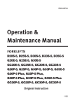
ENGINE MANAGEMENT SYSTEM - 3
Engine Management System - Overview
The ECM (Engine Control Module) is the brain of the
Engine Management System. The ECM is responsible
for maintaining the proper spark and fuel delivery for all
operating conditions of the engine. To provide optimum
drivability and emissions, the ECM monitors various input
or sensor signals in order to calculate ignition control and
fuel delivery. The following devices provide these inputs
to the ECM:
• ECT, the Engine Coolant Temperature sensor,
• IAT, the Intake Air Temperature sensor
• TP, the Throttle Position sensor,
system uses a Distributor to route spark to each cylinder
from a single ignition control (IC) circuit and coil.
The 5.0/5.7L engines use a Camshaft (CMP) sensor
to generate a signal named CAM Retard. The CAM
Retard specification in degrees ensures proper rotor to
cap positioning to prevent ignition crossfire. Refer to the
Master Specifications for each model year engine for the
correct setting.
6.0/6.2L engines use the Electronic Ignition system. This
system uses eight individual ignition control (IC) circuits
and coils. When starting the 6.0/6.2L engines, the ECM
fires two coils for each IC signal until #1 cylinder can
be located by the ECM. The 6.0/6.2L engines use a
• KS, the Knock Sensor(s),
• MAP, the Manifold Absolute Pressure sensor,
• TCP, the Throttle Control Position sensor,
(8)
COIL/IGNITION
CONTROL MODULE
DISTRIBUTOR
ASSEMBLY
• HO2, the Heated Oxygen sensors,
COIL/IGNITION
CONTROL MODULE
• CKP, the crankshaft sensor, and
• CMP, the camshaft sensor.
CAM
POSITION
SENSOR
(CMP)
ENGINE
COOLANT
TEMPERATURE
SENSOR
(ECT)
MANIFOLD AIR
PRESSURE (MAP)
SENSOR
INTAKE AIR
TEMPERATURE (IAT)
SENSOR
CRANK
POSITION
SENSOR
(CKP)
KNOCK
SENSOR (KS)
CRANK
POSITION
SENSOR
(CKP)
TYPICAL FOR 5.0/5.7L
CAM
POSITION
SENSOR
(CMP)
TYPICAL FOR 6.0L
(6.2L IS SIMILAR)
THROTTLE CONTROL
POSITION (TCP)
SENSOR
PEG
45
46
75
76
15
1
31
61
Camshaft (CMP) sensor to identify the compression stroke
of TDC position of #1 cylinder, allowing the ECM to fire
individual cylinders in the firing order sequence.
PEG
16
30
45
46
60
75
76
90
15
1
31
ECM
16
CRANK
POSITION
SENSOR
(CKP)
60
THROTTLE POSITION
SENSOR (TP)
(P/O THROTTLE BODY)
30
ECM
90
CAM
POSITION
SENSOR
(CMP)
The failure of critical system components and/or circuits
monitored by the ECM will generate and store Diagnostic
Trouble Codes (DTCs) and illuminate the Malfunction
Indicator Lamp (MIL) or Check Gauges Lamp (CGL) on
the dash panel of boats.
61
Refer to Section 2 of the Diagnostic Manual for a detailed
description of the sensors and ECM.
Refer to Section 4 of the Diagnostic Manual for a detailed
description of the ignition components used.
To control spark and ignition timing the ECM controls one
of two ignition systems. Both systems utilize a crankshaft
sensor (CKP) to create Ignition Control (IC) signals. The
ECM uses these inputs to trigger the ignition coil(s) and
fuel injector circuits.
The MIL or CGL will stay illuminated when the engine is
running as long as the failure is present. If the problem is
intermittent, or has been repaired, the MIL or CGL will stay
illuminated for up to 3 ignition cycles after the problem is
corrected.
5.0/5.7L engines use the Distributor Ignition system. This
L599003-13
30
ENGINE MANAGEMENT SYSTEM - 3
NOTE: When the DTC’s are cleared using the Diacom
scan tool (and the fault is not present), the MIL or CGL will
immediately go out with the engine running.
NOTE: The Malfunction Indicator Lamp (MIL) is AMBER
in color and the Check Gauges Lamp (CGL) is RED in
color. Over-temperature and oil pressure faults illuminate
the CGL, all other faults illuminate the MIL. Many
manufacturers use digital displays for instrumentation.
Faults are indicated through these displays, and DO NOT
use separate lamps.
• Section 7 provides you with symptom
diagnostics, using the PCM Drivability Checklist,
for various malfunctions that do not generate a
trouble code.
Diagnostic Trouble Codes (DTC)
Suspect Parameter Number (SPN) and Failure Mode
Indicator (FMI)
Diagnostic Trouble Codes (DTC) will be set and stored
in the ECM whenever the ECM detects an engine
management failure. These failures, when active, are
reported to the operator through either lamps/buzzers or
through a warning on the digital display.
The DTCs are accessed using Diacom when you check
the ECM for stored codes.
Diagnostic Manual
One of your most important tools for troubleshooting
an Engine Management System problem will be the
Diagnostic Manual. Take some time and familiarize
yourself with the location and information that is contained
in each of the sections. The manual is divided into several
sections.
DTC’s have been commonized through Federal
Regulations. This means that all engine manufacturers
have the same identification numbers for each emission
failure. Failures are now identified by a Suspect
Parameter Number (SPN) and Failure Mode Indicator
(FMI). Both of these numbers are required in order to
identify the exact failure detected.
• Section 1 is General Information on the system,
special tools, an abbreviation definition table
and service instructions for engine harness and
connector problems.
NOTE: Diacom only displays the FMI and SPN numbers.
Be sure to have both these numbers for each fault
displayed. Diacom does not report the DTC number.
Section 1 not only lists the special tools required when
working on an engine management system, but also
specifies requirements for common tools you may already
be using. A test light used for troubleshooting must pass
the test requirements specified in Section 1. A Digital
Multi-Meter must have a minimum input impedance of 10
mega ohms.
During a previous discussion on the PCM Drivability
Checklist, it was noted the reported problem may be
found and corrected during any step of the checklist.
During Step 4, refer to Figure 3-1; you checked for both
system power and starting capabilities of the engine.
You did this when you turned the key to the ON and then
START positions. If the actions described did not occur,
you would have begun troubleshooting and repair of the
Main Electrical System, Engine Mechanical System or
the Fuel System. If we completed Step 4, then we have
determined the basic engine condition to be normal at this
point in our testing.
• Section 2 provides a description and service
instructions for the Engine Control Module
(ECM) and sensors.
• Section 3 describes how the fuel metering
system operates, and provides a description
and service instructions for the different fuel
systems on the engines.
• Section 4 provides a description and service
instructions for the two Ignition Systems used on
the engines.
• Section 5 is the Diagnostic section and provides
you with the procedures, schematic diagrams
and definitions for troubleshooting an engine
management problem.
Section 5 contains your primary diagnostic information,
definitions, diagnostic procedures and wiring diagrams.
While all the information contained in the manual is
important, Section 5 will be your most widely used section
of the manual. You should thoroughly familiarize yourself
with the information contained in this section.
• Section 6 provides a description and service
instructions for the Positive Crankcase
Ventilation (PCV) System.
OBD System Check
Step 5 of the Drivability Checklist, OBD System Check,
is the first diagnostic procedure you will perform for any
remaining drivability issue with the engine.
Important: Starting issues are not the same as starter
issues. If the engine has a cranking problem, diagnose
that problem first, through the Main Electrical system
troubleshooting. If the engine cranks normally (150-200
rpm) but will not start, then you would perform Step 5 of
the PCM Drivability Checklist, the OBD System Check.
While it may seem that almost all problems encountered
with the engine are Engine Management System
problems, in reality, very few actually are. This
perception exists because we are conditioned to begin
troubleshooting by connecting the scan tool and checking
the ECM for trouble codes. What needs to be realized;
this is more a check to eliminate the engine management
system from the troubleshooting effort. When you check
the ECM for stored codes there are basically three results
that may occur:
L599003-13
31
ENGINE MANAGEMENT SYSTEM - 3
1.
The Diacom scan tool cannot communicate
with the ECM.
The OBD System Check is followed by multiple Diagnostic
Procedures. These diagnostic procedures all support
and ensure the successful completion of the OBD System
Check. All the engine management and drivability
troubleshooting procedures will require the successful
completion of the OBD System Check before proceeding
to the next Diagnostic Procedure. If your OBD System
Check fails, you will be referenced to one or more of these
Diagnostic Procedures.
This may be the result of:
(1) a system power failure,
(2) a blown fuse,
(3) a faulty System Relay,
(4) a defective ECM,
(5) a damaged engine harness,
(6) an accessory device connected improperly
into the CAN BUS data circuits.
(8) Diacom improperly installed, or
(9) a defective/out-of-date Diacom interface
cable.
While some of these examples are definitely engine
management system problems, most are outside
conditions or other system failures that appear through the
engine management system.
2.
There is a stored Diagnostic Trouble Code
(DTC).
This may be the result of:
(1) a failed electronic circuit,
(2) low system voltage, or any other condition
which could cause an interruption in system
power, such as a defective ignition switch
or corroded or loose power and ground
connections,
(3) improper shut down of the engine, such as
using the battery switch instead of the ignition
switch,
(4) a defective engine or boat harness, or
(5) a improperly connected device.
3.
There are no stored DTC’s.
Any abnormal condition, from system power to an engine
mechanical problem, can affect the performance and
drivability of the engine.
The fact is, none of these results clearly indicate an
engine management system problem. This is why
just checking for codes is an insufficient check. Stay
on track by using the PCM Drivability Checklist and
perform Steps 1-4 completely prior to Step 5, the OBD
System Check. Finding or not finding a trouble code and
jumping to a conclusion could waste valuable time in your
troubleshooting effort.
L599003-13
32
ENGINE MANAGEMENT SYSTEM - 3
PCM DRIVABILITY CHECKLIST
ENGINE SERIAL NUMBER:
Date:
Dealership Name:
Technician’s Name:
Technician’s Contact Phone #:
Owner/Operator Name:
Person Reporting the problem (if different from owner/operator):
Service Writer or Person that took the problem report:
1) PROBLEM OR SYMPTOM:
:KR¿UVWREVHUYHGWKHV\PSWRP"
:KHQGLGWKHV\PSWRP¿UVWRFFXU"
$Q\UHFHQWFKDQJHRUVHUYLFHZRUNSULRUWRV\PSWRPRFFXUULQJUHSODFHGEHOWVRULPSHOOHUPDMRUHQJLQHRUERDWUHSDLUV
UHFHQWO\UHIXHOHGHWF"
+DVVRPHRQHRWKHUWKDQ\RXUVHOIWULHGWR
FRUUHFWWKHFXUUHQWV\PSWRP"
,I\HVZKDWZRUNZDVGRQH"
$FFHVVRULHV$GGHG5HFHQWO\"
,VWKHV\PSWRPFXUUHQWO\SUHVHQW"
6SHFLDOFRQGLWLRQVLIDQ\UHTXLUHGWRGXSOLFDWHWKHV\PSWRP
Use an additional sheet of paper if more space is required for symptoms or descriptions.
2) CHECK FOR SERVICE UPDATES:
ENGINE SERIAL NUMBER:
ENGINE MODEL NUMBER:
ENGINE HOURS:
HULL NUMBER:
ENGINE:
1RQH$SSO\
3HUIRUPHG
BOAT: 1RQH$SSO\
3HUIRUPHG
3) VISUAL INSPECTION:
Inspection
YES
Inspection
NO
YES
NO
(YLGHQFHRIRU([FHVVLYH:DWHU
LQWKH%LOJH
)OXLGOHYHOVFKHFNHG
/HDNLQJ)OXLGV
)LULQJRUGHUFRUUHFW
&RUUHFWVL]HSURSHOOHUVLQVWDOOHG
8QGHUZDWHUJHDULVXQGDPDJHG
$FFHVVRULHVDGGHG",I\HVFKHFNLWHPV
(YLGHQFHRIDQRYHUKHDW
(QJLQH+DUQHVVFRQQHFWRUV
FRQQHFWHGSURSHUO\
3K\VLFDO'DPDJHZLULQJFRQQHFWRUV
DVVHPEOLHVDQGRemove Spark Plugs
DQGLQVSHFWIRUÀXLGV
&RUURVLRQ
+XOOFOHDQDQGIUHHRIH[FHVVLYHJURZWK
4) VERIFY THE PROBLEM
YES
NO
Does the engine start and continue to go to 3 go to 1
run?
below below
1) Key-ON-Engine-OFF (KOEO)
YES
NO
Fuel Press.
%RWK)XHO3XPSVUXQVHFRQGV
)XHO3UHVVXUHQHDUZRWVSHFL¿FDWLRQ
ZKHQSXPSVUXQ
2) Key-ON-Engine-Running (KOER)
YES
NO
Fuel Press.
YES
JRWR:DWHU7HVW
NO
Fuel Press.
(QJLQHFUDQNV
)XHO3UHVVXUHQHDUZRWVSHFL¿FDWLRQ
HQJLQHFUDQNLQJ
(QJLQH6WDUWVDQGFRQWLQXHVWRUXQ
3) WATER TEST
9HULI\UHSRUWHGV\PSWRP
)XHO3UHVVXUHLGOH
)XHO3UHVVXUHXQGHUORDG#:27
Check Accessories Added:
+HDWHU
6KRZHU
+RW:DWHU7DQN
)OXVK.LW
0XOWL)XQFWLRQ'LVSOD\
6\QFKURQL]HU
$IWHU0DUNHW6WHUHR(TXLSPHQW
$IWHU0DUNHW'HSWK)LVK)LQGHU
$IWHU0DUNHW1DYLJDWLRQDO(TXLSPHQW
VXFKDV*365DGDU6RQDU$XWRSLORW
V\VWHPV
$IWHU0DUNHW5DGLR(TXLSPHQW
/LJKWV
2WKHUSOHDVHOLVW
4A) Revised or additional symptom found?:
1
Figure 3-1 PCM Drivability Checklist
L599003-13
33
ENGINE MANAGEMENT SYSTEM - 3
PCM DRIVABILITY CHECKLIST
5) PERFORM THE OBD SYSTEM CHECK
&2'(635(6(17
Continue to Step 6
',$*1267,&352&('85(86('
6) ISOLATE AND REPAIR THE PROBLEM.
:HUH\RXDEOHWRLVRODWHDQGUHSDLUWKHSUREOHP",IYESFRQWLQXHWRStep 7.
,INOFRPSOHWHWKH'ULYDELOLW\&KHFNOLVWIRU1R&RGHVVWHS$EHORZ,IWKHSUREOHPLVVWLOOQRWUHVROYHGWKHQFDOOIRU
IDFWRU\WHFKQLFDODVVLVWDQFH
6A) NO CODES - ENGINE RUNS - DRIVABILITY SYMPTOM STILL PRESENT
Inspection or Check
YES
NO
5HYLHZ6WHSV1WKUX5
,QVSHFWIXHOIRUFRQWDPLQDWLRQ
(OHFWULFDOO\LVRODWHHQJLQHIURPERDW
3RZHUWUDLQLVDOLJQHG
5HPRYHDQG,QVSHFW'LVWULEXWRU&DS
DQG5RWRU/RQO\
&KHFNrecord,JQLWLRQZLUHUHVLVWDQFH
5HPRYHDQG,QVSHFWHDFKVSDUNSOXJ
3HUIRUPD&RPSUHVVLRQ&KHFN
RQDOOF\OLQGHUVRecord below.
Inspection or Check
YES
NO
WATER TEST
9HULI\&$05HWDUG**/RQO\
3HUIRUPDQFHYHUL¿HGDJDLQVWD
VLPLODUERDWZVDPHHQJLQH
SDFNDJHLIDYDLODEOH
3HUIRUPWKH'LDFRP3RZHU%DODQFH
&KHFNXQGHUORDG#USP
3HUIRUPWKHKDUQHVVµ:LJJOH7HVW
'LDFRPUHFRUGLQJ3UH'HOLYHU\WHVW
7) VERIFY REPAIR HAS CORRECTED THE PROBLEM. &KHFNIRUDQGFOHDUDOOFRGHVIURPWKH(&0PHPRU\
Water test the boat.5XQWKHHQJLQHIRUDPLQLPXPRIWZRPLQXWHVWKHQYHULI\WKDWQRFRGHVKDYHUHWXUQHG
&RQWLQXHZLWK\RXUZDWHUWHVWORQJHQRXJKWRYHULI\WKDWWKHSUREOHPKDVEHHQFRUUHFWHG
** CAM Retard - ‘02 thru ‘06 = 43-47 degrees
‘07 - SN 485993 = 0 - 4 degrees/CES and SN 485994 = 15 + 2 degrees
FRONT
COMPRESSION
PRESSURE:
1
2
Ohms
3
4
Ohms
Ohms
5
6
Ohms
Ohms
7
8
Ohms
psi
1
2
psi
psi
3
4
psi
psi
5
6
psi
7
8
6.0L - 130-215 psi
6.2L - 130-215 psi
Lowest pressure
should be within 70%
of highest pressure.
Minimum cylinder
pressure - 100 psi.
psi
psi
FLYWHEEL END OF ENGINE
ALL V-8 MODELS
COMPRESSION CHECK
5.7 Liter
RH ROTATION
FRONT
FRONT
2
1
5
5
5
6
7
8
7
8
7
8
3
5
6
5
Rotation
PCM Premier Dealer Website - All the Latest
Publications
4
5
3
c
3
3
7
1
5
4
4
2
1
8
2
4
2
8
3
6
8
7
3
6
7
L510016 - 6.0L Engine Mechanical Service Manual
2
4
1
L510015 - 5.0/5.7L Engine Mechanical Service Manual
1
3
L510030 - GCP / 4G Diagnostic Service Manual
1
2
7
6
0DVWHU(QJLQH6SHFL¿FDWLRQ6KHHWV
FRONT
1
6
NO
DISTRIBUTOR
c
REFERENCES:
6.0 / 6.2 Liter
LH ROTATION
4
8
IGNITION WIRE RESISTANCE CHECK
Less than 10,000 ohms/ft
5.0 / 5.7 Liter
LH ROTATION
2
FLYWHEEL END OF ENGINE
ALL V-8 MODELS
4
Ohms
5.0/5.7L - 130-215 psi
6
Ohms
FRONT
Rotation
FLYWHEEL END OF ENGINE
ALL V-8 MODELS
FIRING ORDER:
1-8-4-3-6-5-7-2
FIRING ORDER:
1-2-7-5-6-3-4-8
FIRING ORDER:
1-8-7-2-6-5-4-3
Figure 3-1 PCM Drivability Checklist
L599003-13
34
ENGINE MANAGEMENT SYSTEM - 3
OBD SYSTEM CHECK
Step 5 of the PCM Drivability Checklist
procedure. The action performed compared to the result
will dictate your next step in the procedure.
The OBD System Check procedure provides 5 areas of
testing as follows:
Diagnostic procedures may specify actions, test set-ups,
and/or a test procedure to perform as part of a single step.
• Checks the ECM’s ability to transmit data.
• Malfunction Indicator Lamp circuit.
• Tests the ability of the engine management
system to allow the engine to start and run and/
or set trouble codes.
Step 1 specifies a number of preliminary actions you must
perform before the actual test. As part of Step 1, the OBD
System Check incorporates three steps we discussed as
part of the PCM Drivability Checklist (Figure 3-1). These
include:
1. Review of Service Updates,
• Checks for trouble codes and then directs you
to the next diagnostic procedure.
2. a Visual Inspection,
3. Condition of the Starter and System Power.
• Diagnostic troubleshooting steps.
When you follow the PCM Drivability Checklist, these
checks will have been accomplished before you begin this
procedure.
As you can see from the descriptions, you have
accomplished much of the OBD System Check when you
connected the scan tool and checked for trouble codes.
Be sure to do the complete OBD System Check for any
engine management or drivability concerns. Remember
that skipping steps may cause you to skip over the cause
of a problem.
When you complete an action or test sequence in a
diagnostic procedure, the procedure will ask you a YES/
NO question about the result. The OBD System Check
Step 1 asks “Does the scan tool display ‘ECM Data’?”.
The answer determines the correct path to proceed to in
the procedure.
It is not practical to cover every Diagnostic Procedure
in the diagnostic manual. The layout of the On-Board
Diagnostic System Check is representative of each of
the diagnostic procedures you will find in Section 5 of
the Diagnostic Manual. Each diagnostic procedure
incorporates the following:
• a schematic or drawing of the circuit under test,
• a Circuit Description,
• Diagnostic Aids,
• Test Description and
• Diagnostic Procedure.
Some steps are diagnostic checks for communications
problems of the ECM. One step of this procedure is an
example of how the Test Descriptions can aid you in your
troubleshooting. In this case, there is a Note referring
you to the Test Descriptions. The Test Description for
this provides you with conditions that can affect the
transmission of CAN BUS data to the scan tool. One is a
faulty scan tool; the other is an suspect auxiliary device(s)
possibly wired into the CAN BUS circuit. Both are
conditions that can affect the outcome of your test.
Even though some diagnostic steps do not have ‘Test
Descriptions’, you should always read the Test Description
information available for the step you are performing, prior
to executing a diagnostic procedure. Test Description
information can prevent you from coming to an erroneous
result and spending unnecessary time troubleshooting a
problem.
The schematic and circuit description provided are a
snap-shot of the circuit being tested. Diagnostic Aids
are inspections and tests, in addition to the diagnostic
procedure, that may help you better isolate the problem.
Test Descriptions define or clarify Diagnostic Procedure
steps. It is good shop practice to always:
• Review the schematic,
NOTE: A Note directing you to read the “Test
Descriptions” is not always located in the test step. Always
read “Test Descriptions” prior to performing the diagnostic
procedure.
• Read the Circuit Description,
• Read the Diagnostic Aids, and
• Read the Test Descriptions that relate to
the steps of the Diagnostic Procedure being
performed prior to actually performing any of the
tests.
NOTE: Not all diagnostic procedures, or steps in a
diagnostic procedure have Test Descriptions.
Refer to the beginning of the OBD System Check
diagnostic procedure.
You will always begin each diagnostic procedure at
the top. You may or may not perform every step in a
L599003-13
35
ENGINE MANAGEMENT SYSTEM - 3
B+
Starter
Solenoid
ECM
Ground
ECM
Ground
69
56
Battery
Feed
100
amp
fuse
Battery
Feed
60
FUEL PUMP
RELAY Fuse 20A
79
RED
To PANEL
Maxi Fuse
40A
RE
D
Engine
Control
Module
(ECM)
ECM/BAT
Fuse 20A
S107
To 100a Alt.
Connector
Term. "D"
RED/
PPL
STARTER
RELAY
Maxi
Fuse 20A
Ground Stud
S106
RED
RED
To Ignition
Coil Connector
(port)Term. "H"
(Bank 1)
Diagnostic
Connector Fuse
15A
To Ignition
Coil Connector
(stbd)Term. "H"
(Bank 2)
S127
30
86
OBDM
Diagnostic
Connector
D C
B
Ignition
Relay
A
PPL
87
85
From
S102
(Ignition)
IGN 1
Fuse
20A
87A
Not Used
S111
PPL
PPL
8-Pin Boat
Harness
Connector
Check Gauges
Lamp (CGL)
Circuit
Malfunction
Indicator
Lamp (MIL)
IGN 2
Fuse
20A
WHT/
LT BLU
To CAM/Phaser
Sensor Conn.
Term. "D"
GRY/
BLK
GRN/
YEL
To Port Post-O2
Term. "C"
Engine
Control
Module
(ECM)
57
Check Gauges
Lamp (CGL)
Circuit
S128
To Port Pre-O2
Term. "C"
80
14
Malfunction
Indicator
Lamp (MIL)
Circuit
15
PNK/
DK GRN
To STB Post-O2
Term. "C"
PNK/
DK GRN
Port Fuel
Injector
Connectors
(1,3,5,7)
To STB Pre-O2
Term. "C"
STB Fuel
Injector
Connectors
(2,4,6,8)
71
Ignition
Relay
CAN CAN
BUS BUS
1
1
(+) (-)
On-Board Diagnostic (OBD) System Check
Circuit Description
The on-board diagnostic system check must be the starting
point for any drivability complaint diagnosis. Before using
this procedure, you should perform a careful visual/physical
check of the ECM and engine grounds for being clean and
tight.
The on-board diagnostic system check is an organized
approach to identifying a problem created by an electronic
engine control system malfunction.
Diagnostic Aids
An intermittent may be caused by a poor connection, rubbed
through wire insulation or a wire broken inside the insulation.
Check for the following items:
• Inspect the ECM harness and connectors for improper
mating, broken locks, improperly formed or damaged
terminals, poor terminal to wire connection and
damaged harness.
•
•
•
Conditions of the starting system that require repair
before proceeding are no crank or slow crank conditions.
Always verify battery condition and connections prior to
troubleshooting starter issues. Crank with no start and
hard start conditions are addressed by this procedure.
The Malfunction Indicator Lamp data display should be
“ON” steady with the ignition “ON,” engine “OFF.” If it
is a steady “OFF”, DP A-1 should be used to isolate the
malfunction. If the MIL is slowly blinking, this indicates
a diagnostic trouble code is stored.
Verify your Diacom Installation and cables on a known
good engine.
b. Verify that no auxiliary devices are plugged into the
CAN BUS circuit that could be affecting communications.
L599003-13
36
ENGINE MANAGEMENT SYSTEM - 3
OBD System Check
Important:
• Do not perform this diagnostic if there is not a drivability concern, unless another procedure directs you to that diagnostic.
• Before you proceed with diagnosis, search for applicable service updates.
• Before you proceed with diagnosis, perform a visual inspection of the engine for damaged wiring, connections, assemblies or added
accessories.
• If there is a condition with the Main Electrical System, such as a starter or charging system problem, repair that first.
• Ensure the battery has a full charge.
• Ensure the battery cables are clean and tight.
• Ensure the ECM grounds are clean, tight and in the correct location.
• Unless a diagnostic procedure instructs you, DO NOT clear the DTC’s.
Attempt to start the engine.
Does the
engine start
and continue to
run?
If a flooded engine is
suspected, go to wide open
throttle and attempt to restart
the engine.
No
Yes
Does the
engine start
and continue to
run?
Yes
• Ignition ON, engine OFF.
• Install Diacom Diagnostic
Scan Tool (DST)
No
Ignition ON, engine OFF.
• Attempt to connect and
display ECM Engine Data..
• Connect a fuel pressure
gauge to fuel rail.
No
Does the scan
tool connect
and display
ECM data?
• Ignition ON, engine OFF.
Do both fuel
pumps run 2-4
seconds then
turn OFF?
Yes
• Observe the fuel pressure
gauge while the fuel pumps
are running.
No
Yes
Go to First
Step on the
Next Page.
• Using Diacom, display ECM
engine data.
Is fuel pressure near
or at the specified
pressure on the Master
Specification sheet?
Yes
• Ignition ON, engine OFF.
Diagnose Fuel
Pump Circuit
• Observe the MIL driver status
on the Diacom display.
No
Diagnose Fuel Pump
Out of Range
Is the MIL
status ON or
flashing?
No
Yes
• Isolate the engine from the
boat harness using remote
key switch RT0091.
Go to DP-A1.
• Ignition ON, engine OFF.
Yes
• Using Diacom, display ECM
engine data.
• Select the “Codes” tab on the
Diacom display. Make a note
of existing code(s) and clear
the DTC(s).
Is there any
DTC’s stored?
• Start the engine.
No
• Ignition OFF.
• Select the “Codes” tab on the
Diacom display.
• Start the engine and run for at
least 2 minutes.
No
Compare “ECM data values”
displayed on the scan tool to
known good data values.
Refer to Drivability
Checklist.
Did any
noted DTC(s)
return?
Yes
Are the display values
normal or close to the
typical values?
No
L599003-13
37
Refer to DTC Procedure
for the Circuit that is Out
of Range.
Refer to Boat
Diagnostics.
Yes
Go to applicable
DTC Procedure.
ENGINE MANAGEMENT SYSTEM - 3
OBD System Check Continued
• Ignition OFF.
• Refer to the Fuse Block
Pinout Diagram.
• Using a DMM, verify there is
B+ voltage on both sides of
the 15A Diagnostic Fuse.
Yes
Was B+
present at
the fuse?
No
• Ignition OFF.
• Ignition OFF.
• Check for faulty connections or faulty scan
tool.
• Verify the Diagnostic
Connector 15A fuse.
NOTE: See Diagnostic Aids. You must
verify that your Diacom is properly installed,
the correct and current software level and
functions on a known good engine before
proceeding with the tests.
• If a problem is found, replace
the fuse and repeat previous
step.
• If the fuse blows again, check
the OBDM Connector wiring
for a short to ground going to
terminal “A”.
• Disconnect ECM connector.
• Check CAN BUS (+) and (-) wires for
open, short to ground or short to voltage.
• Check the OBDM connector B+ circuit for
open.
• Check the OBDM connector ground circuit
for open or short to voltage.
No
Was a
problem
found?
Yes
Was a
problem
found?
Yes
Repeat OBD
System Check.
No
Repair faulty connections or
replace ECM. Repeat OBD
System Check.
L599003-13
38
Repeat OBD
System Check.
ENGINE MANAGEMENT SYSTEM - 3
15A
IGNITION
15A
DIAG COMM
Clearing Diagnostic Trouble Codes procedure is located in
Section 5 Diagnostic manual. One of the most important
items to note is that the ignition must be cycled OFF or
the code may not be cleared from the ECM’s memory.
It is important to note the conditions under which the
ECM will or will not set a code. Occasionally, during
troubleshooting you may wish to verify that a device
or circuit will or will not set its code. Disabling or
disconnecting the circuit and turning the ignition ON is
not enough to set a code. The engine must be running
to set most codes. Run times vary on when the ECM will
recognize a fault and set a code. In general, the engine
should run for at least two minutes at the specified criteria
in order to set the code you are trying to induce, or to
verify a successful circuit repair.
5A
VSW
20A
ECM
20A
FUEL PUMP
PANEL
STARTER
STARTER
RELAY
IGNITION
RELAY FUEL PUMP
RELAY
2
2 1
2
1
1
2 1
1
2
Clearing Diagnostic Trouble Codes
1. Install scan tool.
2. Start engine.
3. Link Diacom to the ECM.
4. Select “Codes” tab on the Diacom display.
5. Select “Erase Trouble Codes”.
IMPORTANT: If the code(s) do not clear when you select
“Erase Trouble Codes”, then the code(s) is currently active.
This indicates that the fault is still present in the system,
you must trouble shoot the code(s) and correct the problem
before the code can be cleared.
6. Turn ignition “OFF” for at least 5 seconds.
2
87
85
86
1
1
30
87
86 30
85
2
87
86 30
85
7. Turn ignition “ON” and read DTC’s. If DTC’s are still
present, check “Notice” below and repeat procedure
following from step 2.
Figure 3-2 - FUSE BLOCK PIN-OUT DIAGRAM
When you successfully complete the OBD System Check
you will have accomplished one of the following actions:
1.
Identified and corrected the problem by performing
one or more of the diagnostic procedures which
supports the completion of the OBD System
Check.
2.
Identified and corrected the problem by
performing the Diagnostic Procedure for a stored
Diagnostic Trouble Code (DTC).
3.
Completed the OBD System Check with no DTCs
present, and the drivability symptom still present.
Items 1 and 2 above would require you to execute the
additional diagnostic procedures you were directed to by
the OBD System Check.
Item 3 requires you to complete the checks and
inspections previously discussed as part of Step 6 of the
PCM Drivability Checklist. Refer to Figure 3-1, the PCM
Drivability Checklist, Step 6A and Figure 3-3, Drivability
Checklist - No Codes Troubleshooting Tree.
It is important to note the conditions under which the
ECM will or will not set a code. Occasionally, during
troubleshooting you may wish to verify that a device
or circuit will or will not set its code. Disabling or
disconnecting the circuit and turning the ignition ON is
not enough to set a code. The engine must be running
to set most codes. Run times vary on when the ECM will
recognize a fault and set a code. In general, the engine
should run for at least two minutes at the specified criteria
in order to set the code you are trying to induce, or to
verify a successful circuit repair.
NOTICE: When clearing DTC’s, the ignition must be
cycled to the “OFF” position or the DTC’s will not clear.
L599003-13
39
ENGINE MANAGEMENT SYSTEM - 3
Malfunction Indicator Lamp (MIL) Trouble
Codes
The majority of the trouble codes that the ECM stores are
for emission related conditions. The AMBER Malfunction
Indicator Lamp (MIL) is triggered for emission related
faults. If the boat contains a Digital Display in the dash,
in most cases the MIL is not used. All faults are displayed
through the digital display.
Remember that DTC’s have been commonized through
Federal Regulations. This means that all engine
manufacturers have the same identification numbers for
each emission failure. Failures are now identified by a
Suspect Parameter Number (SPN) and Failure Mode
Indicator (FMI). Both of these numbers are required in
order to identify the exact failure detected.
NOTE: Diacom ONLY reports the SPN and FMI numbers.
The scan tool does not report the DTC number.
The trouble codes help isolate the problem area to things
such as: circuit short to ground, circuit open, circuit short
to voltage or Bank 1 or 2 problem. These trouble codes
also define sensor identification when multiple sensors
are used such as knock sensors, O2 sensors or exhaust
manifold water temperature sensors.
These trouble codes are diagnosed using the same logic
previously stated as part of the PCM Drivability Checklist.
Each trouble code has a corresponding Diagnostic
Procedure. The Diagnostic Procedure will help determine
if the condition was caused by:
1. A defective sensor or switch.
2. A faulty circuit or wiring.
3. A mechanical condition.
Once the cause has been determined, apply
the procedures located in the service manual or
troubleshooting tree that apply to the problem.
The following gives an example for the Engine Coolant
Temperature (ECT) sensor Low Voltage. As you can see,
the DTC is 0117; however, the important identification
numbers that Diacom would display are SPN 110, FMI 4.
Using the Engine Coolant Temperature (ECT) sensor Low
Voltage as an example, you can see the DTC is 0117;
however, the important identification numbers that Diacom
would display are SPN 110, FMI 4.
The facing page for each Diagnostic Procedure contains
information that describes the fault condition to set this
code. This information can be very useful when you are
trying to recreate the problem or verify a repair. In many
cases, the ECM will use a “default” value when a circuit
failure has been detected. In this case, the ECM uses a
default value of 165°F. Normally on this failure, the ECM
would see a value from the ECT around 300°F. With that
temperature, the ECM would not deliver near enough fuel
to keep the engine running properly. The “default” value is
what Diacom is displaying in this situation..
L599003-13
40
ENGINE MANAGEMENT SYSTEM - 3
DTC 0117 - ECT Sensor Circuit Low Voltage
SPN - 110; FMI - 4
ECT Signal
40
A
5VDC
B
20
Thermistor
5Vrtn1
ECT Sensor
•
•
•
•
•
ECM
Engine Coolant Temperature Sensor
Check Condition - Engine Running
Fault Condition - ECT sensor voltage less than 0.050 volts
Corrective Action(s) - Sound audible warning or illuminate secondary warning lamp, disable adaptive learn fueling
correction during active fault, or any combination thereof as defined in calibration. Recommend a power derate 1/2
to reduce the possibility of engine damage due to the inability to sense temperature.
Non-emissions related fault
The Engine Coolant Temperature sensor is a thermistor (temperature sensitive resistor) located in the engine coolant.
This is used for engine airflow calculation, ignition timing control, to enable certain features, and for engine protection.
The ECM provides a voltage divider circuit so when the sensor reading is cool the sensor reads higher voltage, and
lower when warm.
This fault will set if the signal voltage is less than 0.050 volts. The ECM will use a default value for the ECT sensor in
the event of this fault.
Ignition ON, Engine OFF
• Key OFF
Does DST display
ECT Sensor Volts
< 0.5 volts?
Yes
• Disconnect ECT sensor electrical
connector
• Key ON, Engine OFF
No
Intermittent Problem
• Carefully inspect
wiring for chaffed or
damaged areas.
• Inspect the connectors
for being loose or
damaged.
• Inspect terminals
for damage or not
seating properly in the
connector.
Does DST display
ECT Sensor Volts
> 4.5 volts?
Yes
Replace faulty ECT sensor
No
• Using a DMM, check for
ECT sensor signal circuit
shorted to ground
• Was a problem found?
No
Replace faulty ECM.
L599003-13
41
Yes
Repair faulty ECT signal circuit
as necessary.
ENGINE MANAGEMENT SYSTEM - 3
DRIVABILITY CHECKLIST - NO CODES
Inspect or correct recent
service work performed.
6A-1
Review the results of Steps
1-5
6A-2
Inspect fuel for contamination water, correct fuel type, ect.
Correct fuel/fuel system
as necessary.
6A-3
Verify powertrain
alignment.
Correct alignment
as required.
6A-4
Remove and Inspect the
Distributor Cap and Rotor.
(5.0/5.7L Only)
Replace Cap and
Rotor as necessary.
6A-5
Ignition Wire Resistance check
Record results.
Replace spark plug
wires as necessary.
6A-6
Remove and Inspect each spark
plug for damage or abnormal
condition.
Replace spark plugs
as necessary.
6A-7
Perform a Compression Check
on all 8 cylinders and record.
Refer to the Engine
Mechanical Service
Manual.
WATER TEST
6A-8
6A-9
Verify
Cam Retard (5.0/5.7L only)
Adjust as required.
Performance verified against
Same
a simialr boat w/same
engine package
6A-10
Perform the Diacom
Power Balance Test.
6A-11
Perform the harness
Wiggle Test.
6A-12
Pre-Delivery Diacom
recording.
Normal operation.
Refer to the
Diagnostic Manual
Isolate and repair wiring
or connector problems.
Isolate and repair circuits
outside of normal parameters.
Figure 3-3 PCM Drivability Checklist - No Codes Troubleshooting Tree
L599003-13
42
ENGINE MANAGEMENT SYSTEM - 3
Check Gauges Lamp (CGL) Trouble Codes
Most of the trouble codes that the ECM stores for
conditions detrimental to the engine and/or transmission
turn on a RED Check Gauges Lamp, if equipped. The
AMBER Malfunction Indicator Lamp is triggered for
emission related faults. If the boat contains a Digital
Display in the dash, in most cases neither lamp is used.
All faults are displayed through the digital display. The
ECM may enter into Power Derate Mode should one of the
following conditions occur:
• an engine overheats (Cooling System failure),
• low engine oil pressure (Engine Mechanical
failure), and
• exhaust cooling system overheats (indicated
by an Exhaust Manifold Water Temperature
sensors located in each manifold on CES
equipped engines).
Power Derate Mode is a reduced performance mode that
will allow an owner/operator sufficient performance to
seek service and repairs. Power Derate Mode limits the
engine RPM at two different stages. When the cooling
temperature or oil pressure indicates a reading exceeding
the Stage 1 value, the ECM limits the throttle body to 35%
maximum throttle. If the problem continues to get worse
and reaches a reading exceeding Stage 2 values, the
ECM limits the throttle body to an elevated idle speed.
Warning: The ECM never intentionally shuts the
engine down. If the engine has low oil pressure or
an over temp condition, the operator has to make
the decision to shut the engine down or get to a safe
location.
The following are good examples of problems reported
through the Engine Management System that may be the
result of another engine system failure. In these cases,
the Engine Cooling System, the Exhaust Cooling System
or the Engine Lubrication System may be the cause. By
following the Diagnostic Procedures provided for each of
the trouble codes, you will be able to distinguish the root
cause of the reported failure. Your task is to determine if
the condition was caused by:
• A mechanical condition.
• Improper fluid levels, under or over filled
conditions.
• Fluid restrictions or lack of flow.
Once the cause has been determined, apply the
procedure located in the service manual that applies to the
problem.
L599003-13
43
C
ED
LT GRN/RED
Oil
Pressure
Sensor
N/R
44
A
B
L
R
TG
Figure 3-3 Sensor and Power Derate Circuits
L599003-13
BLK/WHT
BLK/WHT
To Port Post-O2
Term. "A"
To Ignition Coil
Conn. (port)
Term. "E"
BLK/WHT
To Port Pre-O2
Term. "A"
BLK/WHT
Engine
Control
Module
(ECM)
EMWT 1
Sensor
Signal
(port)
41
TAN/
RED
A
BLK/
WHT
B
A
BLK/WHT
Engine Coolant
Temperature
(ECT) Sensor
TAN/
WHT
To STB Post-O2
Term. "A"
BLK/
WHT
Motor
(-)
Motor
(+)
BLK/WHT
A
B
To STB Pre-O2
Term. "A"
To MAP
Sensor
Conn.
Term.
"2"
BLK/
WHT
C
Ground
5 Volt
Reference Sensor
E
TAN/
ORN
83
82
40
PNK/
WHT
Motor
(-)
Motor
(+)
ECT
Sensor
Signal
S119
BLK/
WHT
Exhaust B
Manifold
Water
Temp.
(EMWT)
Sensor
(port)
To IAT
Sensor
Conn.
Term.
"B"
To CAM/
Phaser
Sensor
Conn.
Term. "A"
To TCP
Sensor
Conn.
Term. "6"
LT GRN/
RED
BLK/WHT
To Crank
Sensor
Conn.
Term.
"A"
ED
To CAM/Phaser Sensor
Conn. Term. "B"
LT
GRN/
RED
LT
To MAP
Sensor
Conn.
Term.
"1"
S128
19
5 Volt
Reference
/R
N
GR
LT
BLU
53
Oil Pressure
Sensor
Signal
Sensor
Ground
20
BLK/
WHT
S119
TP
Sensor 2
Signal
F
LT
BLU/
BLU
6
TP
Sensor 2
Signal
BLK/WHT
BLK/WHT
TAN/
RED
A
EMWT 2
Sensor
Signal
(stbd)
11
Exhaust B
Manifold
Water
Temp.
(EWMT)
Sensor
(stbd)
BLK/WHT
To Ignition Coil
Conn. (stbd)
Term. "E"
To TCP Sensor
Conn. Term. "1"
To Crank Sensor
(-)/3" from conn.
Throttle Position (TP)
Sensor/Actuator
(Throttle Body)
BLK/WHT
TP
Sensor 1
Signal
D
PPL/
LT
BLU
5
TP
Sensor 1
Signal
Engine
Control
Module
(ECM)
ENGINE MANAGEMENT SYSTEM - 3
ENGINE MANAGEMENT SYSTEM - 3
TROUBLESHOOTING A POWER DERATE CONDITION
Check Service Updates
Verify Power Derate Mode
Verify System voltage is within specifications
Perform OBD System Check
Trouble Code
Check ECM for trouble codes
SPN 110; FMI 15 (DTC 116)
ECT Higher than Expected Stage 1
Perform Diagnostic Procedure
For Engine Coolant
Temperature (ECT) Overheat
SPN 110; FMI 0 (DTC 217)
ECT Higher than Expected Stage 2
SPN 441; FMI 15 (DTC 1415)
EMWT 1 Higher than Expected Stage 1
SPN 441; FMI 0 (DTC 1417)
EMWT 1 Higher than Expected Stage 2
Perform Diagnostic Procedure
For Exhaust Manifold Water
Temperature (EMWT) Overheat
SPN 442; FMI 15 (DTC 1416)
EMWT 2 Higher than Expected Stage 1
SPN 442; FMI 0 (DTC 1418)
EMWT 2 Higher than Expected Stage 2
SPN 100; FMI 1 (DTC 524)
Oil Pressure Sensor Low Pressure
Perform Diagnostic Procedure
For Low Oil Pressure
Corrective Action
Check/Clear ECM of codes
Verifiy corrective action has corrected the problem
Figure 3-4 Power Reduction Mode Troubleshooting Tree
L599003-13
45
ENGINE MANAGEMENT SYSTEM - 3
Engine Coolant Temperature (ECT) Higher
than Expected Stage 1 / Stage 2 Set
Refer to Figure 3-5 and 3-6.
Engine Coolant Temperature (ECT) Higher than Expected
Stage 1 / Stage 2 indicates that the ECM has detected
an engine over-temperature condition. The ECT sensor
provides the over-temperature reading to the ECM.
These trouble codes will be set and Power Derate
Mode may be enabled when the ECT detects a coolant
temperature in excess of 200°F (Stage 1) and 205°F
(Stage 2). You would perform the Over-Temperature
Troubleshooting Tree, Figure 3-6 of your Reference
Material, which will be discussed in more detail in the
Cooling System section of this course.
These trouble codes illuminate the Check Gauges Lamp
(CGL). When equipped, the CGL is RED. In many models,
these trouble codes are reported through a digital dash
display.
L599003-13
46
C
ED
LT GRN/RED
Oil
Pressure
Sensor
N/R
47
A
B
L
R
TG
Figure 3-5 Power Derate Mode - ECT Circuit
L599003-13
BLK/WHT
BLK/WHT
To Port Post-O2
Term. "A"
To Ignition Coil
Conn. (port)
Term. "E"
BLK/WHT
To Port Pre-O2
Term. "A"
BLK/WHT
Engine
Control
Module
(ECM)
EMWT 1
Sensor
Signal
(port)
41
TAN/
RED
A
BLK/
WHT
B
A
BLK/WHT
Engine Coolant
Temperature
(ECT) Sensor
TAN/
WHT
To STB Post-O2
Term. "A"
BLK/
WHT
Motor
(-)
Motor
(+)
BLK/WHT
A
B
To STB Pre-O2
Term. "A"
To MAP
Sensor
Conn.
Term.
"2"
BLK/
WHT
C
Ground
5 Volt
Reference Sensor
E
TAN/
ORN
83
82
40
PNK/
WHT
Motor
(-)
Motor
(+)
ECT
Sensor
Signal
S119
BLK/
WHT
Exhaust B
Manifold
Water
Temp.
(EMWT)
Sensor
(port)
To IAT
Sensor
Conn.
Term.
"B"
To CAM/
Phaser
Sensor
Conn.
Term. "A"
To TCP
Sensor
Conn.
Term. "6"
LT GRN/
RED
BLK/WHT
To Crank
Sensor
Conn.
Term.
"A"
ED
To CAM/Phaser Sensor
Conn. Term. "B"
LT
GRN/
RED
LT
To MAP
Sensor
Conn.
Term.
"1"
S128
19
5 Volt
Reference
/R
N
GR
LT
BLU
53
Oil Pressure
Sensor
Signal
Sensor
Ground
20
BLK/
WHT
S119
TP
Sensor 2
Signal
F
LT
BLU/
BLU
6
TP
Sensor 2
Signal
BLK/WHT
BLK/WHT
TAN/
RED
A
EMWT 2
Sensor
Signal
(stbd)
11
Exhaust B
Manifold
Water
Temp.
(EWMT)
Sensor
(stbd)
BLK/WHT
To Ignition Coil
Conn. (stbd)
Term. "E"
To TCP Sensor
Conn. Term. "1"
To Crank Sensor
(-)/3" from conn.
Throttle Position (TP)
Sensor/Actuator
(Throttle Body)
BLK/WHT
TP
Sensor 1
Signal
D
PPL/
LT
BLU
5
TP
Sensor 1
Signal
Engine
Control
Module
(ECM)
ENGINE MANAGEMENT SYSTEM - 3
48
Figure 3-6 Engine Over Temperature - With Codes Troubleshooting Tree
L599003-13
Clear ECM of codes
and Verify Repair
Inspect and test Circulating
Pump. Replace as required.
Clear ECM of codes
and Verify Repair
Fresh Water Cooling - Verify
Heat Exchanger raw water
passages are free of debris,
silt and scale. Clean or replace
as necessary.
Raw Water or Fresh Water Replace thermostat. Inspect
housing for debris and proper
seating of the thermostat.
Fresh Water cooling - Verify
coolant is at the proper level.
Refer to the FWC Coolant Loss
Troubleshooting Tree.
Check Raw Water Pump
output path for restrictions.
Use an Infrared Thermometer
to locate ‘hot spots’.
Repair as required.
PASS
Verify Repair.
CAN BUS Gauges - Verify
correct operation of other
CAN gauges. If OK, replace
faulty boat display. If other
gauges inoperative, repair
CAN BUS circuit problem.
Normal Operation
YES
Check for faulty boat
display or ECM output
driver. Repair as necessary.
Verify Repair.
Repeat Raw Water
Pump Volume Test.
Verify Repair.
Clear ECM of codes
Inspect raw water pump
housing bearing seal for
damage, replace if
necessary. Replace raw
water pump Impeller and
housing gasket.
Inspect intake water
path for leaks,
restrictions, or blockage;
repair as required.
Inspect raw water pump
input and output paths for
debris. Clear debris from hoses,
t-stat housing, oil cooler, and
heat exchanger; as required.
Inspect the Raw Water Pump
Impeller for damage.
Clear ECM of codes
and Verify Repair
Replace ECT.
NO
Analog Gauges - Check
wiring/connections
between ECM Temperature
Gauge Driver and the boat
display. Repair as required.
ECT temperature reading is within
5 degrees of the Infrared Thermometer.
Operate engine while observing ‘Coolant
Temperature’ on Diacom display. Verify
displayed temperature with an Infrared
Thermometer at the ECT sensor and T-Stat
housing locations.
ECT, Infrared Thermometer
NO
and boat display are within
10 degrees of each other
YES
FAIL
IF DTC 118 is present, perform
that diagnostic procedure
as outlined in the Diagnostic
Manual.
Perform Raw Water Pump
Volume Test. Output was
5 gallons (min.), 15 seconds,
@ 3000 RPM.
TROUBLESHOOTING AN OVER-TEMPERATURE CONDITION
ENGINE MANAGEMENT SYSTEM - 3
ENGINE MANAGEMENT SYSTEM - 3
Exhaust Manifold Water Temperature (EMWT)
1 and/or 2 Higher than Expected Stage 1 /
Stage 2 Set
Refer to Figure 3-7 and 3-8.
Exhaust Manifold Water Temperature (EMWT) Higher than
Expected Stage 1 / Stage 2 indicates that the ECM has
detected an exhaust water over-temperature condition.
The EMWT sensors provide the over-temperature reading
to the ECM. There is an EMWT sensor in each exhaust
manifold. EMWT 1 refers to the ODD cylinder (Left) side
of the engine and EMWT 2 refers to the EVEN cylinder
(Right) side of the engine.
These trouble codes will be set and Power Derate
Mode may be enabled when either EMWT sensor
detects a temperature in excess of 220°F (Stage 1) and
225°F (Stage 2). You would perform the EMWT OverTemperature Troubleshooting Tree, Figure 3-8, which will
be discussed in more detail in the Cooling System section
of this course. These trouble codes illuminate the Check
Gauges Lamp (CGL). When equipped, the CGL is RED. In
many models, these trouble codes are reported through a
digital dash display..
L599003-13
49
C
ED
LT GRN/RED
Oil
Pressure
Sensor
N/R
50
A
B
L
R
TG
Figure 3-7 Power Derate Mode - EMWT Circuits
L599003-13
BLK/WHT
BLK/WHT
To Port Post-O2
Term. "A"
To Ignition Coil
Conn. (port)
Term. "E"
BLK/WHT
To Port Pre-O2
Term. "A"
BLK/WHT
Engine
Control
Module
(ECM)
EMWT 1
Sensor
Signal
(port)
41
TAN/
RED
A
BLK/
WHT
B
A
BLK/WHT
Engine Coolant
Temperature
(ECT) Sensor
TAN/
WHT
E
BLK/WHT
To STB Post-O2
Term. "A"
BLK/
WHT
A
Motor
(-)
B
Motor
(+)
To STB Pre-O2
Term. "A"
To MAP
Sensor
Conn.
Term.
"2"
BLK/
WHT
C
Ground
5 Volt
Reference Sensor
TAN/
ORN
83
82
40
PNK/
WHT
Motor
(-)
Motor
(+)
ECT
Sensor
Signal
S119
BLK/
WHT
Exhaust B
Manifold
Water
Temp.
(EMWT)
Sensor
(port)
To IAT
Sensor
Conn.
Term.
"B"
To CAM/
Phaser
Sensor
Conn.
Term. "A"
To TCP
Sensor
Conn.
Term. "6"
LT GRN/
RED
BLK/WHT
To Crank
Sensor
Conn.
Term.
"A"
ED
To CAM/Phaser Sensor
Conn. Term. "B"
LT
GRN/
RED
/R
N
GR
To MAP
Sensor
Conn.
Term.
"1"
S128
19
5 Volt
Reference
LT
LT
BLU
53
Oil Pressure
Sensor
Signal
Sensor
Ground
20
BLK/
WHT
S119
TP
Sensor 2
Signal
F
LT
BLU/
BLU
6
TP
Sensor 2
Signal
BLK/WHT
BLK/WHT
TAN/
RED
A
EMWT 2
Sensor
Signal
(stbd)
11
Exhaust B
Manifold
Water
Temp.
(EWMT)
Sensor
(stbd)
BLK/WHT
To Ignition Coil
Conn. (stbd)
Term. "E"
To TCP Sensor
Conn. Term. "1"
To Crank Sensor
(-)/3" from conn.
Throttle Position (TP)
Sensor/Actuator
(Throttle Body)
BLK/WHT
TP
Sensor 1
Signal
D
PPL/
LT
BLU
5
TP
Sensor 1
Signal
Engine
Control
Module
(ECM)
ENGINE MANAGEMENT SYSTEM - 3
ENGINE MANAGEMENT SYSTEM - 3
TROUBLESHOOTING AN EXHAUST MANIFOLD WATER TEMPERATURE
HIGHER THAN EXPECTED STAGE 1/STAGE 2 CONDITION
Check Service Updates
Trouble Code
Check ECM for trouble codes
SPN 441; FMI 15 (DTC 1415)
EMWT 1 Higher than Expected Stage 1
SPN 441; FMI 0 (DTC 1417)
EMWT 1 Higher than Expected Stage 2
Perform Diagnostic Procedure
For Engine Coolant
Temperature (ECT) Overheat
SPN 442; FMI 15 (DTC 1416)
EMWT 2 Higher than Expected Stage 1
SPN 442; FMI 0 (DTC 1418)
EMWT 2 Higher than Expected Stage 2
Raw Water Systems
Full Fresh Water Systems
Check for restrictions in hoses
fittings and exhaust
components.
Thermostatically Controlled
Exhaust Cooling Parial Systems
Perform Exhaust Cooling
System Thermostat Inspection/
Cleaning.
Perform
Corrective Action
Check/Clear ECM of codes
Verifiy corrective action has corrected the problem
Figure 3-8 Exhaust Coolant Over Temperature - With Codes Troubleshooting Tree
L599003-13
51
ENGINE MANAGEMENT SYSTEM - 3
Low Oil Pressure Telltale Set.
Refer to Figures 3-9 and 3-10.
The Low Oil Pressure trouble codes indicates the ECM
has detected a low oil pressure condition. The oil pressure
sensor provides the oil pressure information to the ECM.
This trouble code will be set and Power Derate Mode may
be enabled when the oil pressure sensor detects an oil
pressure less than 5 psi at idle or less than 24 psi at 4000
RPM. The diagnostics are linear between idle and 4000
RPM. This means if the engine was at 2000 RPM, the
diagnostic limit would be less than 16 psi. Using a sensor
instead of a switch allows for much better protection
throughout the RPM range. You would perform the Low
Oil Pressure Troubleshooting Tree, Figure 3-10. This
trouble code illuminates the Check Gauges Lamp (CGL).
When equipped, the CGL is RED. In many models, these
trouble codes are reported through a digital dash display.
This is a good example of a problem reported through
the Engine Management System that may be the result
of another engine system failure. In this case the
Engine Lubrication System. By following the Diagnostic
Procedures provided for this trouble code, you will be able
to distinguish between the system being monitored and a
possible engine management system failure.
L599003-13
52
C
LT GRN/RED
Oil
Pressure
Sensor
D
/RE
53
A
B
G
LT
RN
Figure 3-9 Power Derate Mode - Oil Pressure Circuit
L599003-13
BLK/WHT
BLK/WHT
To Port Post-O2
Term. "A"
To Ignition Coil
Conn. (port)
Term. "E"
BLK/WHT
To Port Pre-O2
Term. "A"
BLK/WHT
Engine
Control
Module
(ECM)
41
EMWT 1
Sensor
Signal
(port)
TAN/
RED
A
BLK/
WHT
B
A
BLK/WHT
Engine Coolant
Temperature
(ECT) Sensor
TAN/
WHT
BLK/WHT
To STB Post-O2
Term. "A"
BLK/
WHT
A
Motor
(-)
B
Motor
(+)
To STB Pre-O2
Term. "A"
To MAP
Sensor
Conn.
Term.
"2"
BLK/
WHT
C
Ground
5 Volt
Reference Sensor
E
TAN/
ORN
83
82
40
PNK/
WHT
Motor
(-)
Motor
(+)
ECT
Sensor
Signal
S119
BLK/
WHT
Exhaust B
Manifold
Water
Temp.
(EMWT)
Sensor
(port)
To IAT
Sensor
Conn.
Term.
"B"
To CAM/
Phaser
Sensor
Conn.
Term. "A"
To TCP
Sensor
Conn.
Term. "6"
LT GRN/
RED
BLK/WHT
To Crank
Sensor
Conn.
Term.
"A"
ED
To CAM/Phaser Sensor
Conn. Term. "B"
LT
GRN/
RED
/R
N
GR
To MAP
Sensor
Conn.
Term.
"1"
S128
19
5 Volt
Reference
LT
LT
BLU
53
Oil Pressure
Sensor
Signal
Sensor
Ground
20
BLK/
WHT
S119
TP
Sensor 2
Signal
F
LT
BLU/
BLU
6
TP
Sensor 2
Signal
BLK/WHT
BLK/WHT
TAN/
RED
A
EMWT 2
Sensor
Signal
(stbd)
11
Exhaust B
Manifold
Water
Temp.
(EWMT)
Sensor
(stbd)
BLK/WHT
To Ignition Coil
Conn. (stbd)
Term. "E"
To TCP Sensor
Conn. Term. "1"
To Crank Sensor
(-)/3" from conn.
Throttle Position (TP)
Sensor/Actuator
(Throttle Body)
BLK/WHT
TP
Sensor 1
Signal
D
PPL/
LT
BLU
5
TP
Sensor 1
Signal
Engine
Control
Module
(ECM)
ENGINE MANAGEMENT SYSTEM - 3
ENGINE MANAGEMENT SYSTEM - 3
TROUBLESHOOTING A POWER DERATE MODE
LOW OIL PRESSURE TROUBLE CODE SET
Perform OBD System Check
SPN 100; FMI 1 (DTC 524)
Oil Pressure Sensor Low Pressure
Verify Engine Oil Level.
Add or remove oil as
required to bring oil to the
Full level on the dipstick.
NOTE: An engine over-filled with oil can aerate
and cause low oil pressure resulting in engine
damage.
Verify oil pressure at idle with a
mechanical oil pressure gauge
at the engine.
LESS THAN
10 PSI
Refer to Engine Mechanical
Manual and troubleshoot
and repair.
NORMAL
PRESSURE
Verify oil pressure under load,
LESS THAN above 4000 RPM, with a
mechanical oil pressure gauge
30 PSI
at the engine.
Verify Repair.
NORMAL
PRESSURE
Disconnect Oil Pressure Sensor.
Ignition ON, engine OFF.
Using a DMM, measure voltage
between connector pins “B” and “A”.
5 vdc Not Present
Troubleshoot and repair 5 volt
and/or ground circuits between
OP sensor and ECM.
5 vdc Present
Troubleshoot and repair
signal circuit between OP
sensor and ECM.
Verify Repair.
Replace ECM.
Verify Repair.
Figure 3-10 Low Oil Pressure - With Codes Troubleshooting Tree
L599003-13
54
Verify Repair.
Replace Oil
Pressure Switch
Verify Repair.
ENGINE MANAGEMENT SYSTEM - 3
DIACOM TESTS
Your Diacom software package is much more than just a
scan tool to read engine parameters and codes. Diacom,
through its ‘Tests’ screen, provides you with control over
various ECM functions. Utilizing these functions can allow
you to test and/or control circuits to determine the source
of a problem more efficiently. On your Diacom screen
you will see a tab for ‘Tests’. Left click on this tab to
reveal the test screen. These tests can be used to assist
in diagnosis, clear ECM data or run through an automated
test cycle. Some of the more commonly used tests are:
• Relay Tests,
• Clear Fuel Adaption,
• Oxygen Sensor Test,
• Injector Kill Test,
• Compression Test Mode, and
• Clear Misfire Data.
The following is a brief description of these Diacom tests
and how they may be used. For more information on
these tests you should refer to your Diacom Help menu.
NOTE: The contents and appearance of the Test Screen
will vary from system to system due to the fact that
different ECMs have different capabilities.
L599003-13
55
ENGINE MANAGEMENT SYSTEM - 3
Relay Tests
When selected this commands the ECM to activate the
driver output for the Ignition Relay, or All Relays.
This command is very useful for troubleshooting engine
management and/or fuel system problems. Once the
ignition switch is in the ‘ON’ position, this command can be
used to turn on the System Relay for electrical diagnosis.
When the ignition is ON, engine OFF, the ECM turns the
Ignition Relay ON for about 5 seconds. If the engine is
not started, the ECM turns OFF the Ignition Relay. If you
were diagnosing the 12 volt circuit supplied to injectors,
ignition coils, O2 sensors or throttle body, you would turn
on the Ignition Relay through Diacom. This would allow
you to take the voltage measurements required without
constantly cycling the ignition ON and OFF. If you need to
turn ON the fuel pumps for priming and/or troubleshooting
purposes, you would select “Turn ALL Relays ON.”
L599003-13
56
ENGINE MANAGEMENT SYSTEM - 3
Clear Fuel Adaption
When selected this commands the ECM to erase all
Learned Fuel Adaption data stored in the ECM.
The Engine Management System controls fuel in a “Closed
Loop” fueling state most of the time. This means the ECM
is taking feedback information from the Oxygen Sensors
and adjusting the fuel delivery to constantly maintain a
near stochiometric air/fuel ratio. This is done in order for
the catalyst to be most affective. Open Loop fueling is
when the engine is cold, during transients (accelerations/
decelerations) and near wide open throttle loads.
Under normal conditions, the ECM learns each application
and populates a table based on engine speed and load.
The adaptive learn allows the ECM to fine tune the fuel
delivery based on variables such as backpressure. By fine
tuning and populating the adaptive learn tables, the engine
management system can precisely control the fuel delivery
for optimal emission reduction.
This function would only be used after a repair is made.
An example would be if a system has a restricted fuel
filter causing fuel pressure to be down a few psi from
specification. In this case, the system would want to run a
little lean. The ECM learns that and adjusts the values for
the adaptive learn. The problem is that it just populated the
table based on a “lean” system. Therefore, once the filter
is replaced and fuel pressure is back to specification, this
function would “Clear the Adaptive Learn” tables and allow
the ECM to relearn a normal system again.
L599003-13
57
ENGINE MANAGEMENT SYSTEM - 3
Oxygen Sensor Test
When selected this commands the ECM to enter into an
“Automated Test Mode”.
The Engine Management System controls fuel delivery
based on Oxygen Sensor feedback. The system
also monitors the efficiency of the catalyst system by
monitoring Oxygen sensors prior to the catalyst substrate
(pre O2 sensors) and Oxygen sensors after the catalyst
substrate (post O2 sensors).
This test allows for the technician to run diagnostics on
ALL four oxygen sensors. The test requires the engine to
be idling in neutral. The test will automatically increase
the RPM to about 1200 RPM. All four oxygen sensors are
checked for the ability to report a lean air/fuel mixture,
a rich air/fuel mixture or heater circuit control. The test
usually takes several minutes.
This function can be used to help diagnose a faulty
oxygen sensor circuit or to validate a repair to any of the
four oxygen sensors or circuits.
L599003-13
58
ENGINE MANAGEMENT SYSTEM - 3
• bad cylinder – (a compression check of the
cylinder will isolate this problem)
Injector Kill Test
This is an extremely useful test for isolating ignition, fuel,
and mechanical problems to a specific cylinder of the
engine. This test is part of Step 6A, of the PCM Drivability
Checklist, that has been previously discussed. You can
use this test as a starting point when troubleshooting
ignition problems, fuel system problems, and various
symptomatic problems such as a misfire conditions, loss
of power, and rough running.
Best results are obtained when this test is performed with
the engine under load (in gear), running between 16001800 RPM. RPM changes are more easily seen and
heard when the engine is under load.
Warning: Please follow all engine and boat
manufacturer’s safety precautions and stay clear of all
moving engine components while running this test.
The Injector Kill Test allows you to turn OFF the injector
driver output to a selected cylinder which, in turn, will
greatly aid you in determining if that particular cylinder is
functioning properly. When you shut OFF an injector to
a properly operating cylinder, the engine RPM or pitch
will change, indicating that the cylinder was indeed shut
off. Typically you will see a 150-200 RPM drop when a
cylinder is shut off. If there is no change in RPM, you may
have a cylinder malfunction. Cylinder malfunctions can
be fuel, spark or mechanical in nature. Some of the more
common causes for a cylinder not firing are:
• bad spark plug – fouled or broken
• bad spark plug wire – broken or too high in
resistance
• bad distributor cap and rotor (5.0/5.7L only) or a
coil/ignition module
• faulty wiring between a coil/module and ECM
• fuel injector failing to fire or leaking (bad injector
or faulty wiring between the injector and ECM)
L599003-13
59
ENGINE MANAGEMENT SYSTEM - 3
Compression Test Mode
The Compression Test is a special test mode that the
ECM provides to allow a technician to safely perform a
cylinder compression check. The Compression Test
Mode is not really a “test” in itself, it is simply a mode or
“state” the engine management system enters to allow
a technician to manually perform a compression check
without the possibility of the engine firing or starting.
Warning: This test commands the ECM to disable
all spark and fuel injector outputs. The test must
be properly exited from within Diacom in order to
re-enable normal spark and fuel operation. Do not
perform this test at sea.
The Compression Test should only be performed
dockside or at a service facility since the engine will be
disabled until the test is properly exited. If the Diacom’s
communication cable is disconnected from the engine
during the Compression Test, the engine will remain in a
disabled state. You must reconnect Diacom, re-enter the
Compression Test mode and then properly exit the test.
When the Compression Test is active, spark and fuel
delivery functions will be disabled on the engine. When
you have completed your compression test procedures
simply click the Stop Test button.
L599003-13
60
ENGINE MANAGEMENT SYSTEM - 3
Clear Misfire Data
When selected this commands the ECM to erase all
Misfire data stored in the ECM.
The ECM constantly monitors various inputs to determine
if a cylinder is misfiring. The ECM stores data every time a
cylinder misfires. This data is stored for each cylinder. This
data can be retrieved through the “System Info” tab using
your Diacom.
Misfires can be damaging to the catalyst system if ignored.
There are two levels of misfire trouble codes associated
with the engine management system. There is “Cylinder
Misfire” trouble codes for each cylinder and there is
“Catalyst Damaging Misfire” trouble codes for each
cylinder.
Abnormal vibrations to the crankshaft can also be induced
by such things as: bent propshaft or bent prop.
This function would only be used after a repair is made. An
example would be if an engine was diagnosed to have a
bad spark plug wire on cylinder #3. In this case, the ECM
has detected and accumulated misfire data on cylinder #3.
Once the spark plug wire is replaced and the problem is
corrected, this function would reset the ECM misfire data
back to 0.
Caution: Resetting misfire data before a repair of a
misfire condition can cause the system to NOT detect
an actual misfire under certain operating conditions.
L599003-13
61
ENGINE MANAGEMENT SYSTEM - 3
BASIC TROUBLESHOOTING APPROACH
Obtain a clear concise description
of the problem
Check for applicable Service Updates
Perform a visual inspection of
the engine for obvious faults
Verify the Problem
Perform the On-Board-Diagnostic
(OBD) System Check
Isolate and Repair the Problem
Check/Clear Trouble Codes from ECM
Verify the Problem has been Corrected
Figure 3-14 Basic Troubleshooting Approach Tree
L599003-13
62
NOTES
L599003-13
63
NOTES
L599003-13
64
Section 4
Fuel
System
L599003-13
L
L5
59
99
90
00
0
033--13
3
13
65
6
5
FUEL SYSTEM - 4
Fuel System
With the ever increasing sophistication of the engine’s
systems, the fuel system has had major changes over the
years.
When troubleshooting a fuel system problem, your primary
tool will be a Fuel Pressure Gauge. You should also have
available:
1. Diacom
2. DMM
The Fuel System is comprised of two distinct sub-systems
the Fuel Supply and the Fuel Metering Systems.
3. Auxiliary fuel tank
1. Fuel Supply System
4. A graduated container
• Fuel Tank
Previously we discussed the actions that occur when the
ignition switch is placed in the ‘ON’ position, Step 4 of the
PCM Drivability Checklist, Figure 4-2. While observing the
fuel pressure rising to the required specification on the fuel
pressure gauge, we were to listen to, and feel, both fuel
pumps to verify that they were running.
• Fuel Filters
• Fuel Pumps
• Fuel Lines
2. Fuel Metering System
Once the ignition is in the ‘ON’ position, you can use your
Diacom ‘Tests’ screen to select and cycle the fuel pumps.
• Fuel Rail
• Fuel Injectors
Using this test allows you to remain next to the engine and
cycle the fuel pumps whenever a test procedure calls for:
• Fuel Pressure Regulator
The operation of the Fuel System and the precise delivery
of fuel to the engine are controlled by the ECM.
Refer to Figure 4-1, Fuel System Diagrams. As you can
see in the diagrams, the pressure regulator is located on
the fuel rail on 5.0L and 5.7L applications. The pressure
regulator is located in the Fuel Control Cell (FCC) on 6.0L
and 6.2L applications.
• individually testing each fuel pump, and/or
• priming the fuel system.
NOTE: Diacom Relay test enables both fuel pumps. If
testing an individual pump, the electrical connector for the
other pump can be disconnected during testing.
Remember to always verify fuel pressure during a lake
test, at wide-open-throttle, under load. This is the most
accurate reading you can take on the fuel system. If the
fuel pressure is correct under load, at wide-open-throttle,
your fuel system is functioning correctly.
L599003-13
66
FUEL SYSTEM - 4
PRESSURE
REGULATOR
Fuel Control Cell Fuel System
FUEL RAIL ASSEMBLY
LOWPRESSURE
FUEL
PUMP
FUEL
CONTROL
CELL
ENGINE
FUEL
FILTER
FUEL
TANK
FUEL SYSTEMS - TYPICAL
Fuel Control Cell Fuel System
(Returnless Fuel Rail)
FUEL RAIL ASSEMBLY
PRESS.
REG.
ENGINE
LOWPRESSURE
FUEL
PUMP
FUEL
FILTER
FUEL
CONTROL
CELL
FUEL
TANK
M4054P
2-12-04
Figure 4-1 Typical Fuel System Configurations
L599003-13
67
FUEL SYSTEM - 4
PCM DRIVABILITY CHECKLIST
ENGINE SERIAL NUMBER:
Date:
Dealership Name:
Technician’s Name:
Technician’s Contact Phone #:
Owner/Operator Name:
Person Reporting the problem (if different from owner/operator):
Service Writer or Person that took the problem report:
1) PROBLEM OR SYMPTOM:
:KR¿UVWREVHUYHGWKHV\PSWRP"
:KHQGLGWKHV\PSWRP¿UVWRFFXU"
$Q\UHFHQWFKDQJHRUVHUYLFHZRUNSULRUWRV\PSWRPRFFXUULQJUHSODFHGEHOWVRULPSHOOHUPDMRUHQJLQHRUERDWUHSDLUV
UHFHQWO\UHIXHOHGHWF"
+DVVRPHRQHRWKHUWKDQ\RXUVHOIWULHGWR
FRUUHFWWKHFXUUHQWV\PSWRP"
,I\HVZKDWZRUNZDVGRQH"
$FFHVVRULHV$GGHG5HFHQWO\"
,VWKHV\PSWRPFXUUHQWO\SUHVHQW"
6SHFLDOFRQGLWLRQVLIDQ\UHTXLUHGWRGXSOLFDWHWKHV\PSWRP
Use an additional sheet of paper if more space is required for symptoms or descriptions.
2) CHECK FOR SERVICE UPDATES:
ENGINE SERIAL NUMBER:
ENGINE MODEL NUMBER:
ENGINE HOURS:
HULL NUMBER:
ENGINE:
1RQH$SSO\
3HUIRUPHG
BOAT: 1RQH$SSO\
3HUIRUPHG
3) VISUAL INSPECTION:
Inspection
YES
NO
Inspection
YES
NO
(YLGHQFHRIRU([FHVVLYH:DWHU
LQWKH%LOJH
)OXLGOHYHOVFKHFNHG
/HDNLQJ)OXLGV
)LULQJRUGHUFRUUHFW
&RUUHFWVL]HSURSHOOHUVLQVWDOOHG
8QGHUZDWHUJHDULVXQGDPDJHG
$FFHVVRULHVDGGHG",I\HVFKHFNLWHPV
(YLGHQFHRIDQRYHUKHDW
(QJLQH+DUQHVVFRQQHFWRUV
FRQQHFWHGSURSHUO\
3K\VLFDO'DPDJHZLULQJFRQQHFWRUV
DVVHPEOLHVDQGRemove Spark Plugs
DQGLQVSHFWIRUÀXLGV
&RUURVLRQ
+XOOFOHDQDQGIUHHRIH[FHVVLYHJURZWK
4) VERIFY THE PROBLEM
YES
NO
Does the engine start and continue to go to 3 go to 1
run?
below below
1) Key-ON-Engine-OFF (KOEO)
YES
NO
Fuel Press.
%RWK)XHO3XPSVUXQVHFRQGV
)XHO3UHVVXUHQHDUZRWVSHFL¿FDWLRQ
ZKHQSXPSVUXQ
2) Key-ON-Engine-Running (KOER)
YES
NO
Fuel Press.
YES
JRWR:DWHU7HVW
NO
Fuel Press.
(QJLQHFUDQNV
)XHO3UHVVXUHQHDUZRWVSHFL¿FDWLRQ
HQJLQHFUDQNLQJ
(QJLQH6WDUWVDQGFRQWLQXHVWRUXQ
3) WATER TEST
9HULI\UHSRUWHGV\PSWRP
)XHO3UHVVXUHLGOH
)XHO3UHVVXUHXQGHUORDG#:27
Check Accessories Added:
+HDWHU
6KRZHU
+RW:DWHU7DQN
)OXVK.LW
0XOWL)XQFWLRQ'LVSOD\
6\QFKURQL]HU
$IWHU0DUNHW6WHUHR(TXLSPHQW
$IWHU0DUNHW'HSWK)LVK)LQGHU
$IWHU0DUNHW1DYLJDWLRQDO(TXLSPHQW
VXFKDV*365DGDU6RQDU$XWRSLORW
V\VWHPV
$IWHU0DUNHW5DGLR(TXLSPHQW
/LJKWV
2WKHUSOHDVHOLVW
4A) Revised or additional symptom found?:
Figure 4-2 PCM Drivability Checklist
L599003-13
68
FUEL SYSTEM - 4
PCM DRIVABILITY CHECKLIST
5) PERFORM THE OBD SYSTEM CHECK
&2'(635(6(17
Continue to Step 6
',$*1267,&352&('85(86('
6) ISOLATE AND REPAIR THE PROBLEM.
:HUH\RXDEOHWRLVRODWHDQGUHSDLUWKHSUREOHP",IYESFRQWLQXHWRStep 7.
,INOFRPSOHWHWKH'ULYDELOLW\&KHFNOLVWIRU1R&RGHVVWHS$EHORZ,IWKHSUREOHPLVVWLOOQRWUHVROYHGWKHQFDOOIRU
IDFWRU\WHFKQLFDODVVLVWDQFH
6A) NO CODES - ENGINE RUNS - DRIVABILITY SYMPTOM STILL PRESENT
Inspection or Check
YES
NO
Inspection or Check
5HYLHZ6WHSV1WKUX5
,QVSHFWIXHOIRUFRQWDPLQDWLRQ
(OHFWULFDOO\LVRODWHHQJLQHIURPERDW
3RZHUWUDLQLVDOLJQHG
5HPRYHDQG,QVSHFW'LVWULEXWRU&DS
DQG5RWRU/RQO\
&KHFNrecord,JQLWLRQZLUHUHVLVWDQFH
5HPRYHDQG,QVSHFWHDFKVSDUNSOXJ
3HUIRUPD&RPSUHVVLRQ&KHFN
RQDOOF\OLQGHUVRecord below.
YES
NO
WATER TEST
9HULI\&$05HWDUG**/RQO\
3HUIRUPDQFHYHUL¿HGDJDLQVWD
VLPLODUERDWZVDPHHQJLQH
SDFNDJHLIDYDLODEOH
3HUIRUPWKH'LDFRP3RZHU%DODQFH
&KHFNXQGHUORDG#USP
3HUIRUPWKHKDUQHVVµ:LJJOH7HVW
'LDFRPUHFRUGLQJ3UH'HOLYHU\WHVW
7) VERIFY REPAIR HAS CORRECTED THE PROBLEM. &KHFNIRUDQGFOHDUDOOFRGHVIURPWKH(&0PHPRU\
Water test the boat.5XQWKHHQJLQHIRUDPLQLPXPRIWZRPLQXWHVWKHQYHULI\WKDWQRFRGHVKDYHUHWXUQHG
&RQWLQXHZLWK\RXUZDWHUWHVWORQJHQRXJKWRYHULI\WKDWWKHSUREOHPKDVEHHQFRUUHFWHG
** CAM Retard - ‘02 thru ‘06 = 43-47 degrees
‘07 - SN 485993 = 0 - 4 degrees/CES and SN 485994 = 15 + 2 degrees
FRONT
COMPRESSION
PRESSURE:
1
2
Ohms
3
4
Ohms
Ohms
5
6
Ohms
Ohms
7
8
Ohms
psi
1
2
psi
psi
3
4
psi
psi
5
6
psi
7
8
6.0L - 130-215 psi
6.2L - 130-215 psi
Lowest pressure
should be within 70%
of highest pressure.
Minimum cylinder
pressure - 100 psi.
psi
psi
FLYWHEEL END OF ENGINE
ALL V-8 MODELS
COMPRESSION CHECK
5.7 Liter
RH ROTATION
FRONT
FRONT
2
3
4
3
4
3
4
5
6
5
6
5
6
7
8
7
8
7
8
L510030 - GCP / 4G Diagnostic Service Manual
4
5
3
c
Rotation
PCM Premier Dealer Website - All the Latest
Publications
1
3
5
6
5
3
5
4
4
3
2
1
7
7
L510016 - 6.0L Engine Mechanical Service Manual
1
1
L510015 - 5.0/5.7L Engine Mechanical Service Manual
8
2
1
2
8
2
8
7
1
7
6
0DVWHU(QJLQH6SHFL¿FDWLRQ6KHHWV
FRONT
2
6
NO
DISTRIBUTOR
c
REFERENCES:
6.0 / 6.2 Liter
LH ROTATION
1
8
IGNITION WIRE RESISTANCE CHECK
Less than 10,000 ohms/ft
5.0 / 5.7 Liter
LH ROTATION
2
FLYWHEEL END OF ENGINE
ALL V-8 MODELS
4
Ohms
5.0/5.7L - 130-215 psi
6
Ohms
FRONT
Rotation
FLYWHEEL END OF ENGINE
ALL V-8 MODELS
FIRING ORDER:
1-8-4-3-6-5-7-2
Figure 4-2 PCM Drivability Checklist
L599003-13
69
FIRING ORDER:
1-2-7-5-6-3-4-8
FIRING ORDER:
1-8-7-2-6-5-4-3
FUEL SYSTEM - 4
Refer to Figure 4-2. Step 4 of the Checklist was to Verify
the Problem. During that step you performed a number
of steps leading up to verifying the reported symptom.
Figure 4-3 is a Troubleshooting Tree for these steps. As
you can, see two of the tests and observations that you
perform are directly related to the Fuel System.
When the ignition is in the ON position (first 2-4 seconds),
or you cycle the pumps ON using Diacom, there are a
number of possible outcomes that could occur. The best
outcome is that both fuel pumps run and the fuel pressure
rises near the WOT specification. The other possibilities
are one or both pumps do not run, or the pumps run and
fuel pressure is not to specification.
As you can see from Figure 4-3, if the pumps do not
run you would use the KOEO Fuel Pumps Do Not Run
Troubleshooting Tree, Figure 4-4, or the Fuel Pressure
Out Of Range Troubleshooting Tree, Figure 4-7.
L599003-13
70
FUEL SYSTEM - 4
STEP 4
- VERIFY THE PROBLEM IMPORTANT:
YES
FOR REPORTED MAIN ELECTRICAL SYSTEM
PROBLEMS SUCH AS STARTER OR CHARGE
SYSTEM PROBLEMS - STOP!
PERFORM MAIN ELECTRICAL SYSTEM
TROUBLESHOOTING FIRST.
START THE ENGINE
Does the engine start and run?
NO START
4-1
Key-ON-Engine-OFF
Do Both Fuel Pumps Run 2-4 Seconds
then turn off?
NO
Refer to the KOEO - Pump(s) Do Not Run Troubleshooting Tree
YES
Is fuel pressure within
specification while fuel pumps run?
Refer to the Fuel
Pressure-Out-Of-Range
Troubleshooting Tree
NO
YES
4-2 Key-ON-Engine-Running
Refer to the
Starter Circuit
Troubleshooting Tree
Does the engine crank over NO
for 5 seconds if the
engine does not start?
YES
Does fuel pressure rise near specification while
engine cranks, and fuel pumps run 2-4 seconds
after the engine stops cranking if engine
does not start?
NO
Perform the OBD
System Check
YES
Does the engine start and continue
to run?
NO
Perform the OBD
System Check
YES
4-3
WATER TEST
Verify the Owner
reported problem.
Is fuel pressure within specification
under load @ W.O.T.
NO
YES
STEP 5 - OBD SYSTEM CHECK
Figure 4-3 Verify the Problem
L599003-13
71
Refer to the Fuel
Pressure-Out-Of-Range
Troubleshooting Tree
FUEL SYSTEM - 4
KOEO – Pump(s) Do Not Run
Refer to Figure 4-4, Key-On-Engine-Off Troubleshooting
Tree. We need to determine the cause of the fuel pump
failure. The cause of this condition could be electrical such
as:
1. An open or shorted wiring circuit,
2. A faulty relay,
3. A bad fuel pump,
requirement. The ECM can be damaged if the nonpowered test lamp does not meet this requirement.
Using your test lamp connected to a know good ground,
test for power at the Fuel Pump Relay socket. Looking at
the main power diagram you can see that we are testing
each device and harness connection on the way to the
fuel pumps. If step 3 checks are good, continue to step
4 and verify the harness connections and power to the
pumps.
Step 4 will verify the harness connections and power to
the pumps. When you jumper pin 30 to pin 87 of the Fuel
Pump Relay Socket, both fuel pumps should run.
4. A blown fuse,
5. A control problem with the ECM .
Looking at the Troubleshooting Tree, you will see that
the first step to perform is the On-Board Diagnostic
(OBD) System Check. Perform this check to determine
if the problem is located in the Fuel System or Engine
Management System. If you find a Fuel Pump Relay
Circuit Open, High or Short to Ground diagnostic trouble
code, you will diagnose the Engine Management System
problem first. If there are no trouble codes you will need
to take a logical approach to isolating why the fuel pump
or pumps do not run. Refer to the “No Code path”, Figure
4-4.
The second check is for battery voltage at the Fuel
Pump Relay and ECM fuses. Looking at the main
power diagram, we have picked a starting point for
troubleshooting roughly in the middle of the circuit. When
the key switch is in the ‘ON’ position, you can see that
the fuses should have power across them. By taking a
voltage reading between a known good ground and each
fuse, you can then make a decision as to the direction of
your troubleshooting path.
Refer to Figure 4-6. If voltage is not present across the
fuses, the fuel pumps cannot run. If you find a fuse blown,
typically the device or the wiring it protects has shorted
causing too much current flow, and melts the fuse element
open. This may have been caused by a temporary
surge, and replacing the fuse corrects the problem, or the
problem may be more serious.
To determine if the device the fuse protects, or the wiring
caused the fuse to blow, you can disconnect the device,
replace the fuse, and then reapply power and perform
a wiggle test on the wiring. Be sure to wiggle the entire
harness when checking to see if there is a short in the
wiring. If during the wiggle test the fuse blows, you have
a wiring problem at the point in the harness you were
affecting when the fuse blew. If the fuse does not blow,
then the device it is protecting may need to be replaced.
Refer to Figure 4-4 and 4-5, KOEO – Pumps Do Not
Run Troubleshooting Tree and Main Power diagram.
If the fuses are good, we will perform step 3, of the
Troubleshooting Tree.
1. Pumps Do Not Run - Verify battery voltage is present at
both fuel pump connectors.
• Battery Voltage Not Present - Diagnose and
repair harness or connection problem between
relay sockets and fuel pump(s).
• Battery Voltage Present - Verify good ground
circuit and repair as necessary. If OK, check
connections and replace fuel pump(s).
2. Both Pumps Run - Verify battery voltage is present at
both fuel pump connectors.
• Battery Voltage Not Present - Diagnose and
repair harness or connection problem between
relay sockets and fuel pump(s).
• Battery Voltage Present - Verify good ground
circuit and repair as necessary. If OK, check
connections and replace fuel pump(s).
Connect your test lamp between fuel pump relay socket
pins 30 and 85. Cycle the fuel pumps, either with your
Diacom or the ignition switch. The test lamp should
illuminate for 2-4 seconds then go out.
1. Lamp Illuminates - Replace the Fuel Pump
Relay.
2. Lamp Did Not Illuminate - Troubleshoot and
repair the wiring between the ECM and the
relay socket. If the wiring checks out good,
replace the ECM.
Using the Troubleshooting Tree and the main power
diagram, we have taken a logical step-by-step approach
to solving this problem. Similar approaches can be used
to solve most any problem you encounter with the engine.
Let’s look at another fuel system example.
CAUTION: Refer to the Diagnostic Manual for
handling and testing instructions for the ECM before
you troubleshoot any harness problem. Never
disconnect or connect the ECM connectors while
power is applied. The ECM may be damaged.
Step 3 requires the use of a non-powered test lamp.
CAUTION: Before you perform this step you should
verify that your test lamp meets the requirement for
circuit testing. Refer to the Diagnostic Manual for this
L599003-13
72
Step 1
L599003-13
73
NO
Repair connection
between fuse and pin 30.
Repair harness between fuel
pump and Fuel Pump Relay
socket. Verify repair.
NO
YES
Step 3
*
Figure 4-4 KOEO Pumps Do Not Run Troubleshooting Tree
KOEO - Verify battery voltage at both
ECM “battery feed” connector pins.
Verify continuity between relay
socket pin “85” and ECM “fuel pump
relay control” pin. Repair circuit and
retest. If circuits and connections are
good, replace ECM. Verify repair.
NO
*
Unplug ECM connector.
YES
Step 5
Replace Fuel Pump
Relay. Verify repair.
Connect a test light between
pin 30 and 85. Cycle fuel pumps.
Does test light illuminate for
2-4 seconds?
YES
Step 4
Refer to the Diagnostic Manual,
Section 1, for Specifications on
the test lamp used. Refer to
Section 2 and 5 for handling
instructions and connector
locations for the ECM.
Section 3 of the Diagnostic
Manual contains a description
and service instructions for the
Fuel System Components.
Jumper relay socket pin 30 to
87. Do both fuel pumps run?
YES
Verify and repair
connections between
fuel pump and harness
connector. If good,
replace fuel pump.
Verify repair.
Verify battery voltage at
fuel pump connector.
NO
Step 2
*
KEY-ON-ENGINE-OFF
- PUMP(S) DON’T RUN TROUBLESHOOTING TREE
YES
Remove Fuel Pump Relay.
Is battery voltage present
at fuel pump relay socket
pin “30”?
KOEO - verify battery voltage
across the three system fuses.
No Codes
NO
Verify and replace defective fuse and retest.
If fuse blows again troubleshoot and repair short in
the circuit the fuse protects. Verify repair.
Perform Diagnostic Procedure
for the Code(s) present.
Codes Present
Perform the On-Board-Diagnostic
(OBD) System Check
Key-ON-Engine-OFF
Do Both Fuel Pumps Run 2-4 Seconds
Then turn off?
NO
FUEL SYSTEM - 4
FUEL SYSTEM - 4
100 A 70 A
D
SEN
C
EXC
BAT
RED/WHITE
PURPLE/WHITE From Pin “5”
B
8-Pin Boat
Harness
Fuse Block
Panel
Fuse
40A
RED - 6 ga
To - STBD
GRD STUD
BELLHOUSING
BATTERY
100A
LITTLE
FUSE
Starter
Relay Fuse
20A
RED/WHITE 10ga 125 C
100A
12 ga
“7”(8-Pin)
Key Switch START Position
86
30
Key Switch ON Position
Starter
Relay
87A
FUSE
87
To ECM
Control
85
Not Used
TRANSMISSION
NEUTRAL
SAFETY
SWITCH
BAT
To - EXC
Alternator
YELLOW 12 ga
S
“1”(2-Pin)
Starter
YEL/RED
YEL/RED
12 ga
B
LITTLE
STARTER
B
Red/
Purple
A Fuse Block
RED
+
Battery
A
RED
RED
-
A
RED
ALTERNATOR
RED - 6 ga
GRD
2-Pin /
8-Pin
Boat Harness
To - STBD
GRD STUD
BELLHOUSING
BLACK 6 ga
To ECM
Control
I
Ignition
PURPLE
14ga
GROUND ENGINE BLOCK
“5”(8-Pin)
86
30
System
Relay
Fuse Block
87A
Not Used
Red
A
Fuse Block
ECM
Fuse 20A
B
2
A
B
Low Pressure
Fuel Pump
Fuel
Control
Cell
Pnk/Yel
Fuel Pump
Relay Fuse
20A
B
To ECM
Ignition
Relay
Control Pin
A
Fuse Block
A
VSW
Fuse
5A
Purple
B
To ECM
Ignition
Feed Pin
A
Fuse Block
IGN 1
Fuse
20A
B
B
IGN 2
Fuse
20A
86
30
Fuel
Pump
Relay
87A
87
Not Used
85
To Coils/
Module
Light
Blue/
White
Pnk/Yel
To - Elec.
Fuel Pumps
Pnk/Yel
To Injectors/
O2 Sensors
Ground
FROM - ECM
FUEL PUMP
RELAY
CONTROL
BLACK
10ga
125 C
PEG
To Ignition
Control
Module
To - ECM
Ground Pins
16
30
45
46
60
75
76
90
15
1
31
61
1
Fuse Block
To - ECM
Battery
Feed Pins
85
A
Pink/
Black
To - STBD
GRD STUD
BELLHOUSING
87
ALL - STBD
GROUNDS
CENTER
GROUND STUD
BELLHOUSING
(5.0/5.7L ONLY)
PORT
GROUND STUD
BELLHOUSING
(ECM GROUND ONLY)
Figure 4-5 Main Power, Fuse Check
L599003-13
74
STARBOARD
GROUND STUD
BELLHOUSING
“2”(2-Pin)
FUEL SYSTEM - 4
100 A 70 A
A
D
SEN
C
EXC
BAT
Fuse Block
Panel
Fuse
40A
RED - 6 ga
To - STBD
GRD STUD
BELLHOUSING
BATTERY
100A
LITTLE
FUSE
Starter
Relay Fuse
20A
RED/WHITE 10ga 125 C
LITTLE
12 ga
“7”(8-Pin)
Key Switch START Position
86
30
Key Switch ON Position
Starter
Relay
87A
FUSE
87
Not Used
To ECM
Control
85
TRANSMISSION
NEUTRAL
SAFETY
SWITCH
BAT
To - EXC
Alternator
YELLOW 12 ga
S
“1”(2-Pin)
Starter
YEL/RED
YEL/RED
12 ga
B
100A
STARTER
B
Red/
Purple
A Fuse Block
RED
+
Battery
A
RED
RED
-
RED/WHITE
PURPLE/WHITE From Pin “5”
B
8-Pin Boat
Harness
RED
ALTERNATOR
RED - 6 ga
GRD
2-Pin /
8-Pin
Boat Harness
To - STBD
GRD STUD
BELLHOUSING
BLACK 6 ga
To ECM
Control
I
Ignition
PURPLE
14ga
GROUND ENGINE BLOCK
“5”(8-Pin)
86
30
System
Relay
Fuse Block
87A
Not Used
Red
A
Fuse Block
ECM
Fuse 20A
B
2
A
B
Low Pressure
Fuel Pump
Fuel
Control
Cell
Pnk/Yel
Fuel Pump
Relay Fuse
20A
B
To ECM
Ignition
Relay
Control Pin
A
Fuse Block
A
VSW
Fuse
5A
Purple
B
To ECM
Ignition
Feed Pin
A
Fuse Block
IGN 1
Fuse
20A
B
B
IGN 2
Fuse
20A
86
30
Fuel
Pump
Relay
87A
87
Not Used
85
Light
Blue/
White
Pnk/Yel
To - Elec.
Fuel Pumps
Pnk/Yel
To Coils/
Module
To Injectors/
O2 Sensors
Ground
FROM - ECM
FUEL PUMP
RELAY
CONTROL
BLACK
To Ignition
Control
Module
To - ECM
Ground Pins
PORT
GROUND STUD
BELLHOUSING
(ECM GROUND ONLY)
ALL - STBD
GROUNDS
CENTER
GROUND STUD
BELLHOUSING
(5.0/5.7L ONLY)
Figure 4-6 Main Power, Fuel Pumps Power Feed
L599003-13
75
10ga
125 C
PEG
16
30
45
46
60
75
76
90
15
1
31
61
1
Fuse Block
To - ECM
Battery
Feed Pins
85
A
Pink/
Black
To - STBD
GRD STUD
BELLHOUSING
87
STARBOARD
GROUND STUD
BELLHOUSING
“2”(2-Pin)
FUEL SYSTEM - 4
Fuel Pressure is Out-of-RANGE
regulator. Using an auxiliary fuel tank will quickly isolate
this problem.
When we took our first look at the engine and turned the
ignition to ‘ON’ our first observation was to listen and
feel for the fuel pumps to run, and we’ve discussed the
procedure that covers the condition when they do not.
The second observation we needed to make was fuel
pressure. Was the pressure near the WOT specification
while the pumps ran?
The more common condition is fuel pressure below
specification. Refer to Figure 4-7, the “Below Specification
path”. It would appear that pressure below specification is
a complex problem to isolate. By making a couple of tests
we can quickly isolate this problem.
Refer to Figure 4-7, the Fuel Pressure Out-Of-Range
Troubleshooting Tree. Looking at the Troubleshooting
Tree you will observe that this test sequence will require
you to use an auxiliary fuel tank. The use of an auxiliary
fuel tank allows you to isolate the boat’s fuel system from
the engine. The use of the auxiliary tank is a quick and
extremely useful way to determine the source of a problem
when fuel contamination or restriction is suspected. Some
of the more common symptoms are:
Without a sufficient supply of fuel, the high pressure fuel
pump cannot make or maintain pressure. This requires
testing of the fuel delivery to the high pressure fuel pump
located inside the FCC.
• rough running,
• the engine cuts out,
• stalls,
• loses power at high speed, or
• fuel pressure problems.
NOTE: When using an auxiliary fuel source to test an
engine with a FCC that returns fuel to the boat’s fuel tank;
the return fuel from the FCC must be redirected into the
auxiliary fuel source.
Important: Caution must be taken when using the
auxiliary fuel tank. The tank must be properly strapped
down. The lines and fittings must be secure and away
from heat and moving components.
The first test will be to verify an unrestricted supply of fuel.
Without a sufficient supply of fuel, proper fuel pressure
cannot be achieved.
Disconnect the fuel return line from the FCC to the fuel
tank and plug. Attach an adequate length approved fuel
line to the return fitting on the FCC. This is where you
will measure the amount of fuel required during the low
pressure fuel pump volume test.
The Low Pressure Fuel Pump should output at least 16
to 20 ounces of fuel in 10 seconds. Be sure you use an
approved container to capture the fuel output, and have a
graduated measure to verify the quantity of fuel. A onequart glass measuring cup is very useful for this. Not only
can you accurately measure the fuel but you can also see
if you have contamination in the fuel.
Low Pressure Fuel Pump Volume Test
1. Disconnect the return-to-tank fuel line from the FCC.
2. Connect a piece of fuel line between the FCC return
output and an approved empty container.
Refer to Figure 4-7, the Fuel Pressure Out-Of-Range
Troubleshooting Tree. You can see there are two distinct
paths for fuel pressure problems. Pressure could be above
the required specification, or below.
Fuel pressures above specification are uncommon
occurrences. Symptoms of excessive fuel pressure may
be similar to those associated with other engine problems
such as a cold running engine or under temperature
condition. The following is a partial list of symptoms:
Excessive fuel consumption.
Heavy black soot deposit on the transom.
Hard starts, especially on a warm or hot engine.
Erratic idle speed problems, that may include
stalling warm or cold.
Fouled spark plugs, engine missing or backfires.
Owner reports great top end performance but
cannot get through an idle zone without stalling.
Typically, the most common cause of a high fuel pressure
condition will be a restriction in the return to tank fuel
line, such as an anti-syphon valve installed at the tank
instead of a straight through fitting. Less common will
be a restriction in the fuel rail or a failed fuel pressure
3. Remove the Fuel Pump Relay.
4. Jumper relay socket Pin 30 to Pin 87 for 10 seconds,
then disconnect jumper.
5. Verify 16-20 oz. of fuel in the container.
6. Return system to normal configuration.
If the result of the test is low output volume from the
Low Pressure Fuel Pump, the Low Pressure Fuel Pump
volume test will have to be repeated using your auxiliary
fuel tank.
The auxiliary fuel tank is used to isolate the engine’s fuel
system from the boat. Restrictions in the fuel line, antisiphon valve, in-line fuel filter, or in the fuel pick-up tube
are some of the most common causes for the volume
output of the Low Pressure Fuel Pump to be low.
Determining if the problem is on the boat side or engine
side may be accomplished by connecting the auxiliary fuel
tank. Remove the fuel line connection at the input to the
Low Pressure Fuel Pump. Connect the auxiliary fuel tank
directly to the Low Pressure Fuel Pump input and repeat
the Low Pressure Fuel Pump output volume test.
If the Low Pressure Fuel Pump again fails the volume test,
the fuel inlet or outlet is restricted or the pump is defective.
Determine and resolve the problem and verify the repair.
L599003-13
76
FUEL SYSTEM - 4
Refer to Figure 4-7. Once the Low Pressure Fuel Pump
output volume has been verified to be correct; the next
check is an inspection of the high pressure pump and its
output path. The result of that inspection will determine if
we have a pump problem or a metering problem, such as
the pressure regulator or defective fuel injector(s).
If the engine operates normally with the auxiliary fuel
tank, you know that the problem lies somewhere in the
boat’s fuel system such as contaminated fuel, fuel line
restrictions or fuel tank problems.
Inspect the FCC internal fittings and hoses for leaks and
repair as required. If no problem is found, you will need to
replace the high pressure pump. If the pressure is still low,
replace the fuel pressure regulator.
If the problem persists, you know the problem lies in the
engines fuel system and you would inspect for leaks,
failing low pressure pump or failing high pressure pump.
The last step would be to troubleshoot and replace the
faulty fuel injectors. It is important to note that if you have
an injector or injectors stuck open causing a low fuel
pressure problem, you will have multiple symptoms related
to over fueling of the engine.
Some of the more common symptoms of over fueling are
hard to start, possibly slow to crank, rough running at
low RPM, evidence of heavy black soot on the transom
and raw fuel in the exhaust. The Diacom Power Balance
Test can be used to isolate this problem to the specific
cylinder(s) being over fueled.
IMPORTANT: Some additional causes for over-fueling
of the engine include an engine coolant temperature
(ECT) sensor that has shifted in value, a manifold
absolute pressure (MAP) sensor that has shifted in value,
system voltage out of range or a cooling system undertemperature condition. Typically, the aforementioned
conditions will not set a code in the ECM. Be sure to
complete the PCM Drivability Checklist verifying system
power, cooling system operation and verifying system
parameters by comparing a DIACOM recording of a
known good engine against the DIACOM recording of the
suspect engine.
The Fuel pressure troubleshooting procedures discussed
have approached the pressure problem from the stand
point that the fuel pressure is out of tolerance under all
conditions. Always verify fuel pressure is correct under
load, at wide-open-throttle. If the pressure drops or varies
at wide-open-throttle, use your auxiliary fuel tank to
determine if the problem is in the engine’s fuel system or
the boat’s supply components.
Always water test the boat. Verify fuel pressure is
correct under load, at wide-open-throttle. If the pressure
drops or varies at wide-open-throttle, use your auxiliary
fuel tank to determine if the problem is in the engine’s fuel
system or the boat’s supply components.
IMPORTANT: When you connect the auxiliary fuel tank to
the FCC fuel system, always drain the FCC of any old fuel
before you begin the test. The FCC holds sufficient fuel
to perform a water test and you would not get to the fresh
fuel in the auxiliary tank, thus invalidating your test.
L599003-13
77
FUEL SYSTEM - 4
KEY-ON-ENGINE-OFF
FUEL PRESSURE OUT OF RANGE - PUMPS RUN
Below Specification
Above Specification
Verify LPFP output volume.
Connect an auxiliary fuel tank
between the LPFP (inlet) and FCC
(return).
Low Pressure Fuel Pump Volume Test
1. Disconnect the return-to-tank fuel line
from the FCC.
2. Connect a piece of fuel line between
the FCC return output and an approved
empty container.
3. Remove the Fuel Pump Relay.
4. Jumper relay socket Pin 30 to Pin 87
for 10 seconds, then disconnect jumper.
5. Verify 16-20 oz. of fuel in the container.
6. Return system to normal configuration.
Cycle the fuel pumps. Verify
fuel pressure.
At Specification
Troubleshoot and repair
restriction in fuel return
line from FCC to the fuel
tank. Verify repair.
PASS
Above Specification
Replace Fuel Pressure
Regulator. Verify repair.
FAIL
Connect an auxiliary fuel tank
to the input of the LPFP.
Repeat fuel pump volume test.
Fuel volume to spec?
PASS
FAIL
Troubleshoot and repair
fuel restriction on supply
(inlet) side of the LPFP.
Verify repair.
Replace LPFP.
Verify repair.
Inspect and repair FCC
internal high pressure hose,
fittings, and connections.
If good - Replace HP fuel
pump. Verify repair.
Replace Fuel Pressure
Regulator. Verify repair.
Troubleshoot fuel rail for
leaking injector(s) and
repair. Verify repair.
Figure 4-7 KOEO Fuel Pressure Out-Of-Range Troubleshooting Tree
L599003-13
78
NOTES
L599003-13
79
01/13
NOTES
L599003-13
80
Section 5
Main
Electrical
System
L599003-13
L5
L
L599
599
990
00
030331
13
3
81
8
1
MAIN ELECTRICAL SYSTEM - 5
PCM DRIVABILITY CHECKLIST
ENGINE SERIAL NUMBER:
Date:
Dealership Name:
Technician’s Name:
Technician’s Contact Phone #:
Owner/Operator Name:
Person Reporting the problem (if different from owner/operator):
Service Writer or Person that took the problem report:
1) PROBLEM OR SYMPTOM:
:KR¿UVWREVHUYHGWKHV\PSWRP"
:KHQGLGWKHV\PSWRP¿UVWRFFXU"
$Q\UHFHQWFKDQJHRUVHUYLFHZRUNSULRUWRV\PSWRPRFFXUULQJUHSODFHGEHOWVRULPSHOOHUPDMRUHQJLQHRUERDWUHSDLUV
UHFHQWO\UHIXHOHGHWF"
+DVVRPHRQHRWKHUWKDQ\RXUVHOIWULHGWR
FRUUHFWWKHFXUUHQWV\PSWRP"
,I\HVZKDWZRUNZDVGRQH"
$FFHVVRULHV$GGHG5HFHQWO\"
,VWKHV\PSWRPFXUUHQWO\SUHVHQW"
6SHFLDOFRQGLWLRQVLIDQ\UHTXLUHGWRGXSOLFDWHWKHV\PSWRP
Use an additional sheet of paper if more space is required for symptoms or descriptions.
2) CHECK FOR SERVICE UPDATES:
ENGINE SERIAL NUMBER:
ENGINE MODEL NUMBER:
ENGINE HOURS:
HULL NUMBER:
ENGINE:
1RQH$SSO\
3HUIRUPHG
BOAT: 1RQH$SSO\
3HUIRUPHG
3) VISUAL INSPECTION:
Inspection
YES
NO
Inspection
YES
NO
(YLGHQFHRIRU([FHVVLYH:DWHU
LQWKH%LOJH
)OXLGOHYHOVFKHFNHG
/HDNLQJ)OXLGV
)LULQJRUGHUFRUUHFW
&RUUHFWVL]HSURSHOOHUVLQVWDOOHG
8QGHUZDWHUJHDULVXQGDPDJHG
$FFHVVRULHVDGGHG",I\HVFKHFNLWHPV
(YLGHQFHRIDQRYHUKHDW
(QJLQH+DUQHVVFRQQHFWRUV
FRQQHFWHGSURSHUO\
3K\VLFDO'DPDJHZLULQJFRQQHFWRUV
DVVHPEOLHVDQGRemove Spark Plugs
DQGLQVSHFWIRUÀXLGV
&RUURVLRQ
+XOOFOHDQDQGIUHHRIH[FHVVLYHJURZWK
4) VERIFY THE PROBLEM
YES
NO
Does the engine start and continue to go to 3 go to 1
run?
below below
1) Key-ON-Engine-OFF (KOEO)
YES
NO
Fuel Press.
%RWK)XHO3XPSVUXQVHFRQGV
)XHO3UHVVXUHQHDUZRWVSHFL¿FDWLRQ
ZKHQSXPSVUXQ
2) Key-ON-Engine-Running (KOER)
YES
NO
Fuel Press.
YES
JRWR:DWHU7HVW
NO
Fuel Press.
(QJLQHFUDQNV
)XHO3UHVVXUHQHDUZRWVSHFL¿FDWLRQ
HQJLQHFUDQNLQJ
(QJLQH6WDUWVDQGFRQWLQXHVWRUXQ
3) WATER TEST
9HULI\UHSRUWHGV\PSWRP
)XHO3UHVVXUHLGOH
)XHO3UHVVXUHXQGHUORDG#:27
Check Accessories Added:
+HDWHU
6KRZHU
+RW:DWHU7DQN
)OXVK.LW
0XOWL)XQFWLRQ'LVSOD\
6\QFKURQL]HU
$IWHU0DUNHW6WHUHR(TXLSPHQW
$IWHU0DUNHW'HSWK)LVK)LQGHU
$IWHU0DUNHW1DYLJDWLRQDO(TXLSPHQW
VXFKDV*365DGDU6RQDU$XWRSLORW
V\VWHPV
$IWHU0DUNHW5DGLR(TXLSPHQW
/LJKWV
2WKHUSOHDVHOLVW
4A) Revised or additional symptom found?:
Figure 5-1 PCM Drivability Checklist
L599003-13
82
MAIN ELECTRICAL SYSTEM - 5
PCM DRIVABILITY CHECKLIST
5) PERFORM THE OBD SYSTEM CHECK
&2'(635(6(17
Continue to Step 6
',$*1267,&352&('85(86('
6) ISOLATE AND REPAIR THE PROBLEM.
:HUH\RXDEOHWRLVRODWHDQGUHSDLUWKHSUREOHP",IYESFRQWLQXHWRStep 7.
,INOFRPSOHWHWKH'ULYDELOLW\&KHFNOLVWIRU1R&RGHVVWHS$EHORZ,IWKHSUREOHPLVVWLOOQRWUHVROYHGWKHQFDOOIRU
IDFWRU\WHFKQLFDODVVLVWDQFH
6A) NO CODES - ENGINE RUNS - DRIVABILITY SYMPTOM STILL PRESENT
Inspection or Check
YES
NO
Inspection or Check
5HYLHZ6WHSV1WKUX5
,QVSHFWIXHOIRUFRQWDPLQDWLRQ
(OHFWULFDOO\LVRODWHHQJLQHIURPERDW
3RZHUWUDLQLVDOLJQHG
5HPRYHDQG,QVSHFW'LVWULEXWRU&DS
DQG5RWRU/RQO\
&KHFNrecord,JQLWLRQZLUHUHVLVWDQFH
5HPRYHDQG,QVSHFWHDFKVSDUNSOXJ
3HUIRUPD&RPSUHVVLRQ&KHFN
RQDOOF\OLQGHUVRecord below.
YES
NO
WATER TEST
9HULI\&$05HWDUG**/RQO\
3HUIRUPDQFHYHUL¿HGDJDLQVWD
VLPLODUERDWZVDPHHQJLQH
SDFNDJHLIDYDLODEOH
3HUIRUPWKH'LDFRP3RZHU%DODQFH
&KHFNXQGHUORDG#USP
3HUIRUPWKHKDUQHVVµ:LJJOH7HVW
'LDFRPUHFRUGLQJ3UH'HOLYHU\WHVW
7) VERIFY REPAIR HAS CORRECTED THE PROBLEM. &KHFNIRUDQGFOHDUDOOFRGHVIURPWKH(&0PHPRU\
Water test the boat.5XQWKHHQJLQHIRUDPLQLPXPRIWZRPLQXWHVWKHQYHULI\WKDWQRFRGHVKDYHUHWXUQHG
&RQWLQXHZLWK\RXUZDWHUWHVWORQJHQRXJKWRYHULI\WKDWWKHSUREOHPKDVEHHQFRUUHFWHG
** CAM Retard - ‘02 thru ‘06 = 43-47 degrees
‘07 - SN 485993 = 0 - 4 degrees/CES and SN 485994 = 15 + 2 degrees
FRONT
COMPRESSION
PRESSURE:
1
2
Ohms
3
4
Ohms
Ohms
5
6
Ohms
Ohms
7
8
Ohms
psi
1
2
psi
psi
3
4
psi
psi
5
6
psi
7
8
6.0L - 130-215 psi
6.2L - 130-215 psi
Lowest pressure
should be within 70%
of highest pressure.
Minimum cylinder
pressure - 100 psi.
psi
psi
FLYWHEEL END OF ENGINE
ALL V-8 MODELS
COMPRESSION CHECK
5.7 Liter
RH ROTATION
FRONT
FRONT
2
3
4
3
4
3
4
5
6
5
6
5
6
7
8
7
8
7
8
L510030 - GCP / 4G Diagnostic Service Manual
4
5
3
c
Rotation
PCM Premier Dealer Website - All the Latest
Publications
1
3
5
6
5
3
5
4
4
3
2
1
7
7
L510016 - 6.0L Engine Mechanical Service Manual
1
1
L510015 - 5.0/5.7L Engine Mechanical Service Manual
8
2
1
2
8
2
8
7
1
7
6
0DVWHU(QJLQH6SHFL¿FDWLRQ6KHHWV
FRONT
2
6
NO
DISTRIBUTOR
c
REFERENCES:
6.0 / 6.2 Liter
LH ROTATION
1
8
IGNITION WIRE RESISTANCE CHECK
Less than 10,000 ohms/ft
5.0 / 5.7 Liter
LH ROTATION
2
FLYWHEEL END OF ENGINE
ALL V-8 MODELS
4
Ohms
5.0/5.7L - 130-215 psi
6
Ohms
FRONT
Rotation
FLYWHEEL END OF ENGINE
ALL V-8 MODELS
FIRING ORDER:
1-8-4-3-6-5-7-2
Figure 5-1 PCM Drivability Checklist
L599003-13
83
FIRING ORDER:
1-2-7-5-6-3-4-8
FIRING ORDER:
1-8-7-2-6-5-4-3
MAIN ELECTRICAL SYSTEM - 5
Main Electrical System
Engine reliability, performance and safety depend
upon an electrical system that is functioning at peek
efficiency. Marine engines are constructed from electrical
components that meet strict safety and performance
standards. These standards must be maintained to ensure
that the performance and safety features engineered into
PCM engines are not compromised.
This section covers the Main Electrical System. The
primary functions of the Main Electrical System are to
provide an uninterrupted source of constant power to
all electrical sub systems, and to crank the engine for
starting.
We will begin troubleshooting Main Electrical System
problems in the same manner we begin all of our
troubleshooting exercises, by completing the PCM
Drivability Checklist, Figure 5-1. Before you can complete
Step 4 and beyond of the PCM Drivability Checklist,
you must resolve all system power and starter issues.
Low, or no power may not only keep you from starting
the engine, but may cause the ECM to set false codes,
cause improper operation of the engine’s ignition and fuel
systems and may cause erroneous instrument readings.
We will use the following procedures to troubleshoot the
Main Electrical System.
This partial list contains some of the more common
complaints associated with the Main Electrical System:
NOTE: The discussion that follows is for current
production engines. Older models may have different
configurations and illustrations. The following may not
apply to these older models.
1. A dead battery
2. Over- or under-voltage displayed on the volt
gauge
Refer to Figure 5-2. The Main Electrical System consists
of three sub-systems.
3. Slow cranking or no crank of the engine
4. The engine cranks but will not start
1. System Power - The 12 volt Battery and its
associated components and cables.
5. The engine stops and will not restart
6. The engine stops, but will restart
2. Starter Circuit - The Starter and its associated
components and wiring.
7. The engine cuts off and on, or stalls during
operation.
3. Charge Circuit - The Alternator and its
associated components and wiring.
8. The malfunction indicator light (MIL) and/or
warning buzzer lights/sounds during cranking.
No DTC codes are stored in the ECM’s
memory.
It is necessary that a technician servicing PCM engines
maintain the reliability, performance and safety built into
our engines by:
9. Scan Tool does not recognize the ECM.
1. Repairing electrical system components in a
manner consistent with our design standards.
10. Any similar complaint that may be caused by
the loss of a power feed circuit.
2. Replacing defective components with original
equipment parts that meet all of our applicable
marine safety and manufacturer design criteria.
Warning: All PCM electrical components are certified
to meet Coast Guard requirements for ignition
or explosion protection. DO NOT use electrical
components that do not meet the Coast Guard
requirements.
Symptoms of a malfunctioning Main Electrical System may
not always be easily isolated to the Main Electrical System
itself. Many of the symptoms reported could be interpreted
as Engine Management or Fuel System problems, while
others can be directly associated with the Main Electrical
System. As shown in the procedures so far, verifying that
you have sufficient power is one of the very first steps to
perform. In all cases, whether performing the On-Board
Diagnostic System Check or troubleshooting the Fuel
System; having the correct voltage and current available is
essential for proper operation.
L599003-13
84
MAIN ELECTRICAL SYSTEM - 5
100 A 70 A
C
EXC
BAT
Fuse Block
Panel
Fuse
40A
RED - 6 ga
To - STBD
GRD STUD
BELLHOUSING
BATTERY
100A
LITTLE
FUSE
Starter
Relay Fuse
20A
RED/WHITE 10ga 125 C
LITTLE
“7”(8-Pin)
12 ga
86
30
Starter
Relay
87A
FUSE
87
Not Used
To ECM
Control
85
TRANSMISSION
NEUTRAL
SAFETY
SWITCH
BAT
To - EXC
Alternator
YELLOW 12 ga
S
“1”(2-Pin)
Starter
YEL/RED
YEL/RED
12 ga
B
100A
STARTER
B
Red/
Purple
A Fuse Block
RED
+
Battery
A
RED
RED
-
RED/WHITE
PURPLE/WHITE From Pin “5”
B
8-Pin Boat
Harness
RED
ALTERNATOR
A
D
SEN
RED - 6 ga
GRD
2-Pin /
8-Pin
Boat Harness
To - STBD
GRD STUD
BELLHOUSING
BLACK 6 ga
To ECM
Control
I
Ignition
PURPLE
14ga
GROUND ENGINE BLOCK
“5”(8-Pin)
86
30
System
Relay
Fuse Block
87A
Not Used
Red
A
Fuse Block
ECM
Fuse 20A
B
2
A
B
Low Pressure
Fuel Pump
Fuel
Control
Cell
Pnk/Yel
Fuel Pump
Relay Fuse
20A
B
To ECM
Ignition
Relay
Control Pin
A
Fuse Block
A
VSW
Fuse
5A
Purple
B
To ECM
Ignition
Feed Pin
A
Fuse Block
IGN 1
Fuse
20A
B
B
IGN 2
Fuse
20A
86
30
Fuel
Pump
Relay
87A
87
Not Used
85
Light
Blue/
White
Pnk/Yel
To - Elec.
Fuel Pumps
Pnk/Yel
To Coils/
Module
To Injectors/
O2 Sensors
Ground
FROM - ECM
FUEL PUMP
RELAY
CONTROL
BLACK
To Ignition
Control
Module
To - ECM
Ground Pins
PORT
GROUND STUD
BELLHOUSING
(ECM GROUND ONLY)
ALL - STBD
GROUNDS
CENTER
GROUND STUD
BELLHOUSING
(5.0/5.7L ONLY)
Figure 5-2 Main Electrical System Wiring Diagram
L599003-13
85
10ga
125 C
PEG
16
30
45
46
60
75
76
90
15
1
31
61
1
Fuse Block
To - ECM
Battery
Feed Pins
85
A
Pink/
Black
To - STBD
GRD STUD
BELLHOUSING
87
STARBOARD
GROUND STUD
BELLHOUSING
“2”(2-Pin)
MAIN ELECTRICAL SYSTEM - 5
Isolating the Electrical System
The engine is designed to be controlled by the boat’s
mechanical and electrical controls. Problems in these
areas may cause conditions that may be mistaken for
engine defects.
Often it is necessary to determine if the boats electrical
system is the cause of a reported engine problem. It will
be necessary to separate the engine electrical system
from the boats electrical system before testing begins.
Some common symptoms that may indicate the need for
this procedure are:
1. Intermittent crank or starts
2. No crank or no start
3. The engine cuts off and on during operation
Figure 5-2 Remote Key Switch - P/N RT0091
4. Low voltage or dead battery
5. Perceived under- or over-charge conditions
System Power
Refer to Figure 5-3. Isolating the engine harness from
the boat harness is easily done by disconnecting the
boat harness at the engine/boat harness 8-pin and 2-pin
connectors.
Once you have disconnected the boat harness
connectors, verify that you have Battery voltage at Pin
“1” of the engine’s 2-pin connector. Troubleshoot System
Power if voltage is not present.
You can then use a remote key switch, P/N RT0091, at
the engine side of the two connectors to simulate Key
‘ON’ and ‘START’ functions that would normally take place
through the boat harness and the ignition switch.
At the engine’s 8-pin and 2-pin connectors, connect the
remote key switch.
If the engine operates normally with the boat harness
disconnected, you know the problem lies somewhere
within the boat wiring or boat accessory devices. You
would then troubleshoot and repair that problem. If the
problem is still present in the engine, you can now focus
your troubleshooting on the engine.
Refer to Figure 5-3. You should have the following
tools available when troubleshooting the Main Electrical
System:
1. Diacom scan tool
2. DMM
3. Battery Load Tester
Your starting point for any Main Electrical System problem
and most other troubleshooting problems will be the
Battery. Low or no voltage at the ECM, Starter, and other
devices will cause multiple faults and symptoms to occur.
Remember, voltage below 9.6 vdc at the ECM will cause
the ECM to not power up, shut off or reset during cranking.
This may cause an interruption in fuel and/or spark
control, and cause starting or drivability issues. In other
words, low voltage equals a loss of:
1. fuel
2. air
3. spark
NOTE: The remote key switch test harness, P/N RT0091,
can be purchased from the PCM Parts Department.
Figure 5-3 Tools
L599003-13
86
MAIN ELECTRICAL SYSTEM - 5
System Power
Previously we discussed the OBD System Check. Part of
the first step in that procedure was to ensure that:
1. The Battery is good, of the proper size and fully
charged.
2. The Battery cables are clean, tight, properly
connected and in the correct locations.
3. Excessive resistance is not present in the
cable circuits.
2. Refer to Figure 5-5. Inspect the engine power and
ground locations. Clean and repair these connections
as necessary. Proper ground connections are very
important for engine operation. The flywheel housing’s
port ground stud should have only the ECM grounds
from the main engine harness attached. The flywheel
housing’s starboard ground stud should be used for the
battery, all other main engine harness grounds, and all
accessory grounds.
NOTE: The 5.0/5.7L engines utilize the center bolt on
the bell housing as a ground for the Ignition Coil/Module
Assembly. This should be the only ground at this location.
These steps are the basis for the System Power Check.
Let’s take a detailed look at the System Power Check.
System Power – KEY ON
System Power – KEY OFF
3. Refer to Figure 5-6. After checking battery voltage
and battery cable connections, Turn the ignition ‘ON’
and apply a load to the battery by turning ON the
Navigation Lights and boat Courtesy Lamps. Verify
that system power is not less than the battery voltage
by more than 0.3 vdc at the test points shown. The
test points are at junctions, connectors and fuses that
are either routing points for system power or after
major splices in the engine harness. As you take
measurements at each of these points inspect for
tightness of the connectors and inspect for corrosion.
You should clean or repair connections as necessary.
Turn the lights and ignition switch OFF when you have
completed the test.
1. Verify that the battery is the correct size and rating for
the boat; and most importantly, fully charged.
Verify that the battery is the correct size and rating for the
boat; and most importantly, fully charged. To verify the
charge on a battery you will need a battery load tester. To
load test a battery you must:
1. Disconnect both the negative and positive
leads of the battery,
2. Connect your load tester and then load the
battery, per your load tester instructions,
3. Under load, verify the battery voltage to be a
minimum of 9.7 vdc.
4. If the battery check confirms the battery is
good; inspect and clean your battery terminals
and connectors then reconnect the battery.
Example: Battery Voltage is 13.0 vdc; all test points
should read 12.7 – 13.0 vdc. A reading outside of this
range may indicate a bad splice, connection or broken
wire which should be repaired before proceeding with any
other troubleshooting.
NOTE: Test points are labeled on Figure 5-6 for easy
reference. If battery voltage is not available at TP-2
(starter battery terminal). Ensure that the boat’s Battery
Switch (if equipped) is in the correct position before
troubleshooting or replacing the cable.
Once you have verified that the proper voltage and
grounds are available for System Power, you would return
to the test procedure that requested a System Power
check. If the problem you are troubleshooting is a starter
problem or a charge system problem you would return to
the Starter or Charge Circuit Troubleshooting Tree and
complete the troubleshooting.
Always resolve system power, starter or charging,
problems before you perform the On-Board Diagnostic
System Check or any other Engine Management System
troubleshooting procedure.
Figure 5-4 Verify System Power
IMPORTANT – The ECM may reset if voltage drops
below 9.6 vdc. This can cause false codes, and
inaccurate display readings to occur. Always begin your
troubleshooting procedures with a known good battery.
L599003-13
87
MAIN ELECTRICAL SYSTEM - 5
D
A
EXC
C
B
PURPLE/WHITE From Pin “5”
8-Pin Boat
Harness
BAT
Fuse Block
Panel
Fuse
40A
RED - 6 ga
To - STBD
GRD STUD
BELLHOUSING
BATTERY
100A
LITTLE
FUSE
Starter
Relay Fuse
20A
RED/WHITE 10ga 125 C
LITTLE
“7”(8-Pin)
12 ga
86
30
Starter
Relay
87A
FUSE
87
Not Used
To ECM
Control
85
TRANSMISSION
NEUTRAL
SAFETY
SWITCH
BAT
To - EXC
Alternator
YELLOW 12 ga
S
“1”(2-Pin)
Starter
YEL/RED
YEL/RED
12 ga
B
100A
STARTER
B
Red/
Purple
A Fuse Block
RED
+
Battery
A
RED - 6 ga
RED
-
RED/WHITE
RED
ALTERNATOR
100 A 70 A
SEN
RED
GRD
2-Pin /
8-Pin
Boat Harness
To - STBD
GRD STUD
BELLHOUSING
BLACK 6 ga
To ECM
Control
I
Ignition
PURPLE
14ga
GROUND ENGINE BLOCK
“5”(8-Pin)
86
30
System
Relay
Fuse Block
87A
Not Used
Red
A
Fuse Block
ECM
Fuse 20A
B
2
A
B
Low Pressure
Fuel Pump
Fuel
Control
Cell
Pnk/Yel
B
Fuse Block
IGN 1
Fuse
20A
Purple
B
A
To ECM
Ignition
Feed Pin
A
Fuse Block
B
B
IGN 2
Fuse
20A
86
30
Fuel
Pump
Relay
87A
87
Not Used
Pnk/Yel
To - Elec.
Fuel Pumps
Pnk/Yel
ECM operation is dependant upon
85
maintaining properTo ground
locations. The
Coils/
To Injectors/
Light
Module
O2 grounds
Sensors
port ground
stud
is
for
ECM
only.
Blue/
White
Battery
ground and all accessory grounds
FROM - ECM
should
be located at the starboard ground
FUEL PUMP
RELAY CONTROL
stud.
Ground
BLACK
PEG
To Ignition
Control
Module
To - ECM
Ground Pins
ALL - STBD
GROUNDS
CENTER
GROUND STUD
BELLHOUSING
(5.0/5.7L ONLY)
PORT
GROUND STUD
BELLHOUSING
(ECM GROUND ONLY)
Figure 5-5 System Power Ground Locations
L599003-13
88
10ga
125 C
J1-6
CONTROL
16
30
45
46
60
75
76
90
15
1
31
61
1
Fuel Pump
Relay Fuse
20A
A
VSW
Fuse
5A
A
Fuse Block
To - ECM
Battery
Feed Pins
85
To ECM
Ignition
Relay
Control Pin
Pink/
Black
To - STBD
GRD STUD
BELLHOUSING
87
STARBOARD
GROUND STUD
BELLHOUSING
“2”(2-Pin)
MAIN ELECTRICAL SYSTEM - 5
GRD
ALTERNATOR
100 A 70 A
TP-3SEN
TP-4EXC
D
A
C
B
RED/WHITE
PURPLE/WHITE From Pin “5”
8-Pin Boat
Harness
BAT
Fuse Block
TP-5
100A
LITTLE
FUSE
Starter
Relay Fuse
20A
LITTLE
Starter
YEL/RED
Starter
Relay
87A
FUSE
87
Not Used
To ECM
Control
85
TRANSMISSION
NEUTRAL
SAFETY
SWITCH
To - EXC
Alternator
YELLOW 12 ga
S
To ECM
Control
I
Ignition
PURPLE
14ga
GROUND ENGINE BLOCK
System
Relay
Fuse Block
87A
A
B
Fuel Pump
Relay Fuse
20A
2
Pink/
Black
A
B
Low Pressure
Fuel Pump
Fuel
Control
Cell
Pnk/Yel
A
Fuse Block
TP-11
To ECM
Ignition
Feed Pin
A
Fuse Block
IGN 1
Fuse
20A
IGN 2
Fuse
20A
B
B
TP-9
TP-10
86
30
Fuel
Pump
Relay
87A
87
Not Used
85
Light
Blue/
White
Pnk/Yel
To - Elec.
Fuel Pumps
Pnk/Yel
To Coils/
Module
To Injectors/
O2 Sensors
Ground
FROM - ECM
FUEL PUMP
RELAY
CONTROL
BLACK
To Ignition
Control
Module
To - ECM
Ground Pins
PORT
GROUND STUD
BELLHOUSING
(ECM GROUND ONLY)
ALL - STBD
GROUNDS
CENTER
GROUND STUD
BELLHOUSING
(5.0/5.7L ONLY)
Figure 5-6 System Power Test Points
L599003-13
89
10ga
125 C
PEG
16
30
45
46
60
75
76
90
15
1
31
61
1
B
To ECM
Ignition
Relay
Control Pin
TP-8
A
VSW
Fuse
5A
Purple
B
To - ECM
Battery
Feed Pins
85
A
Fuse Block
TP-7
To - STBD
GRD STUD
BELLHOUSING
87
Not Used
Red
Fuse Block
“5”(8-Pin)
86
30
With the Key ‘ON’ and boat’s
nav and panel lights ON, all test
points should read within .3 vdc
of the battery voltage.
ECM
Fuse 20A
“7”(8-Pin)
12 ga
86
30
BAT
STARTER
“1”(2-Pin)
TP-6
100A
TP-2
RED/WHITE 10ga 125 C
YEL/RED
12 ga
B
RED
BATTERY
RED
+
B
Red/
Purple
A Fuse Block
RED
-
Battery
A
RED - 6 ga
RED
TP-1
Panel
Fuse
40A
RED - 6 ga
To - STBD
GRD STUD
BELLHOUSING
2-Pin /
8-Pin
Boat Harness
To - STBD
GRD STUD
BELLHOUSING
BLACK 6 ga
STARBOARD
GROUND STUD
BELLHOUSING
“2”(2-Pin)
MAIN ELECTRICAL SYSTEM - 5
Starter Circuit
NOTE: Starter problems are those associated with
cranking the engine. Starting problems are those
associated with making the engine run. Starter problems
should be addressed before performing any other
troubleshooting procedures.
The most common problems associated with the Starter
Circuit will be:
1. A no crank
2. Slow crank condition
Typically, these conditions may be the result of:
1. A defective ignition switch or control
2. A failing battery
3. A failing starter
4. A faulty starter relay
5. A misadjusted or failed Transmission Neutral
Safety Switch
6. An engine mechanical problem
Refer to Figure 5-7. The starter circuit path is from
the battery positive (+) connection to the Starter BAT
connection, through the 100A fuse to the 20A Starter
Relay Maxi fuse. From the Maxi Fuse to pin “30” of the
Starter Relay.
Power from Pin “1” of the 2-Pin connector is routed
through the boat harness to the Ignition Key Switch.
When the Key Switch is in the START Position power is
routed back through the boat harness to pin “7” of the
engine/boat harness 8-Pin connector to ECM Starter
Circuit pin which energizes the relay. Ground for the
Starter Relay is relay pin “85”, through the neutral safety
switch to the ECM Starter Relay Control circuit pin.
When the Starter Relay closes, power from pin “30” is
routed through the relay to pin “87”, then to the Starter
Solenoid (S) contact causing the Starter to engage and
crank the engine.
The Starter ground path is through the Starter’s case to
the engine block through the starter mounting surface at
the bell-housing. The engine block is grounded through
the negative (-) battery cable back to the Battery negative
(-) terminal or post.
L599003-13
90
MAIN ELECTRICAL SYSTEM - 5
100 A 70 A
D
SEN
C
EXC
BAT
RED/WHITE
PURPLE/WHITE From Pin “5”
B
8-Pin Boat
Harness
Fuse Block
Panel
Fuse
40A
RED - 6 ga
To - STBD
GRD STUD
BELLHOUSING
BATTERY
100A
LITTLE
FUSE
Starter
Relay Fuse
20A
FUSE
TP-2
Not Used
“7”(8-Pin)
12 ga
TP-4
Starter
Relay
BAT
87
TP-5
To ECM
Control
85
TP-6
TRANSMISSION
NEUTRAL
SAFETY
SWITCH
YELLOW 12 ga
S
YEL/RED
86
30
87A
“1”(2-Pin)
Starter
TP-3
LITTLE
STARTER
RED/WHITE 10ga 125 C
YEL/RED
12 ga
B
100A
TP-1
B
Red/
Purple
A Fuse Block
RED
+
Battery
A
RED
RED
-
A
RED
ALTERNATOR
RED - 6 ga
GRD
2-Pin /
8-Pin
Boat Harness
To - STBD
GRD STUD
BELLHOUSING
BLACK 6 ga
To ECM
Control
I
To - EXC
Alternator
TP-7
Ignition
PURPLE
14ga
GROUND ENGINE BLOCK
“5”(8-Pin)
86
30
System
Relay
Fuse Block
87A
Not Used
Red
A
Fuse Block
ECM
Fuse 20A
B
A
B
Low Pressure
Fuel Pump
Fuel
Control
Cell
Pnk/Yel
Fuel Pump
Relay Fuse
20A
B
To ECM
Ignition
Relay
Control Pin
A
Fuse Block
A
VSW
Fuse
5A
Purple
B
To ECM
Ignition
Feed Pin
A
Fuse Block
IGN 1
Fuse
20A
B
B
IGN 2
Fuse
20A
86
30
Fuel
Pump
Relay
87A
87
Not Used
85
Light
Blue/
White
Pnk/Yel
To - Elec.
Fuel Pumps
Pnk/Yel
To Coils/
Module
To Injectors/
O2 Sensors
Ground
FROM - ECM
FUEL PUMP
RELAY
CONTROL
BLACK
To Ignition
Control
Module
To - ECM
Ground Pins
PORT
GROUND STUD
BELLHOUSING
(ECM GROUND ONLY)
TP-8
ALL - STBD
GROUNDS
CENTER
GROUND STUD
BELLHOUSING
(5.0/5.7L ONLY)
Figure 5-7 Starter Circuit Wiring Diagram
L599003-13
91
10ga
125 C
PEG
16
30
45
46
60
75
76
90
15
1
31
61
1
2
Fuse Block
To - ECM
Battery
Feed Pins
85
A
Pink/
Black
To - STBD
GRD STUD
BELLHOUSING
87
STARBOARD
GROUND STUD
BELLHOUSING
“2”(2-Pin)
MAIN ELECTRICAL SYSTEM - 5
Starter Circuit
Refer to Figure 5-8. The Starter Circuit Troubleshooting
Tree lists the steps for troubleshooting starter problems,
starting with:
1. A visual inspection
2. Verify there is no engine mechanical issue
(Result of the spark plug inspection)
3. Check the ECM for a Fuel Injector code or
Engine Overheat code
4. Verify System Power
The most difficult part about troubleshooting a starter
problem will be NOT turning the key to the START position
before the Starter Circuit Troubleshooting Tree instructs
you.
Caution: When you have a reported slow or no
cranking condition – Do Not attempt to crank the
engine until you have performed a physical check
of each spark plug for fluids in a cylinder. If water,
coolant or fuel is in the cylinders, hydrostatically
locking the engine, you may do major engine damage
by attempting to crank the engine.
Always perform the System Power Check before
troubleshooting a starter problem. A known good, fully
charged battery is essential for proper testing. A weak or
failing battery will give false test results.
coolant or fuel is in the cylinders, hydrostatically
locking the engine, you can do major engine damage
by attempting to crank the engine.
The owner/operator may have already damaged the
engine by continuing to attempt to crank an engine that
has fluid in a cylinder(s). By doing this inspection before
you attempt to crank the engine, you may find water,
coolant or fuel in a cylinder before it is pumped out as
the engine starts and runs. You would troubleshoot and
repair the cause of the fluid in the cylinders, then verify the
starter is operating properly.
If fluid is found in the engine cylinder(s) use your Diacom
scan tool to check the ECM for a Fuel Injector Fault code
or Engine Over Temperature code. If present, you may
have found the starting issue. One or more cylinders may
be filled with fuel from a defective injector circuit, or one
or more cylinders may be filled with water from the engine
dieseling after an overheat condition occurred.
Perform the Diagnostic Procedure for the trouble code
present first. Return to the Starter Circuit Troubleshooting
Tree and continue testing to ensure there are no other
engine mechanical issues, and the starter issue is
resolved.
If no codes are present, and there is evidence of fluid in
the cylinders, there are two paths for troubleshooting:
1. If it is fuel, troubleshoot the injector circuit for
that cylinder and repair the wiring or replace
the injector.
Refer Figure 5-8. When you perform the Visual
Inspection, Step 3 of the PCM Drivability Checklist, include
in that inspection:
2. If water or coolant is present, determine the
source of the water or coolant by pressure
testing the exhaust manifolds and elbows.
Determine whether it is a failed exhaust
component, or does the engine need
diagnosed for a problem such as a failed head
gasket.
• All Starter wiring connections are tight and free
of corrosion
• The Starter has no physical and/or water
damage
• The exhaust flaps are present and there are no
exhaust restrictions
• The spark plugs show no evidence of fluid in the
cylinders
• The shift lever in the boat is in the Neutral
position
NOTE: Starters used are permanent magnet starters
and the magnet can be broken if the housing is pounded
on. Also, “Marine” Starter means that the starter is “spark
arrested” and safe to use in the bilge of the boat. It does
not mean that the starter will operate under water.
Once you have corrected a fluid condition in the
cylinder(s), be sure to perform a compression check of
all 8 cylinders to check for indications of other engine
damage. This test is not all conclusive, but may reveal
internal engine damage that could cause major engine
damage. Return to the Starter Circuit Troubleshooting
Tree, at “Verify System Power,” and verify starter
operation.
Refer Figure 5-8. If the spark plugs are dry, Verify System
Power. You must have a known good source of system
power to complete the Starter Circuit testing.
Part of the Visual Inspection, Figure 5-1, will be to remove
all eight spark plugs and inspect them for evidence
of fluids. This check is done to eliminate a possible
mechanical problem for a slow or no crank condition.
Caution: When you have a reported slow or no
cranking condition – Do Not attempt to crank the
engine until you have performed a physical check
of each spark plug for fluids in a cylinder. If water,
L599003-13
92
MAIN ELECTRICAL SYSTEM - 5
STARTER CIRCUIT
TROUBLESHOOTING TREE
Reported symptom is a
Slow or No Crank condition.
From Step 3 of the
PCM Drivability Checklist
When you perform the Visual Inspection
include the Starter Circuit, exhaust system
to include physical damage, missing
exhaust flaps, and exhaust restrictions.
Remove all 8 spark plugs and inspect for
evidence of fluid in the cylinders.
Ensure the shift lever is in Neutral position.
Was fluid found in cylinders
and/or on the spark plugs?
Dry
Correct conditions with the
exhaust system. Continue with
Starter Circuit trouble tree and
verify starter opration.
Verify System Power
Wet
No Codes
Check for Diagnostic
Trouble Codes.
Codes Present
Perform Diagnostic Procedure
for the Code(s) present.
Water/Coolant
Present
Fuel Present
Pressure check exhaust
manifolds and elbows for
leaks.
Perform diagnostics for
system running rich, or
possible fuel injector
stuck open.
Replace faulty exhaust
manifold or elbow, if goodTroubleshoot and repair
engine mechanical.
Once the condition that allowed
fluid into the cylinders is repaired.
Disable fuel and spark by
removing the System Relay.
Perform a compression check on
all 8 cylinders to verify no other
engine damage is present. Return
to ‘Verify System Power’ step on
the Starter Circuit Trouble Tree
and verify starter operation.
Disable fuel and spark by
removing the System Relay.
Key Switch to ‘START’ position
Normal
Perform a compression
check on all 8 cylinders.
Fail
Re-Install spark plugs
No Crank
Re-Install spark plugs
Pass
Re-Install spark plugs
Troubleshoot and repair
engine mechanical
problem.
Slow Crank
Go To
Slow Crank
Trouble Tree
Normal
Operation
Re-Install
System Relay
Figure 5-8 Starter Circuit Troubleshooting Tree
L599003-13
93
Go To
No Crank
Trouble Tree
MAIN ELECTRICAL SYSTEM - 5
15A
IGNITION
15A
DIAG COMM
Starter Circuit Testing
5A
VSW
20A
ECM
20A
FUEL PUMP
NOTE: Always perform the system power check before
troubleshooting a starter problem. A known good, fully
charged battery is absolutely essential for proper testing.
A weak or failing battery will give false test results.
PANEL
STARTER
Slow Crank Condition
Refer to figure 5-9. For a slow crank condition, use a
Clamp Meter to check the current draw of the starter.
Clamp the meter on the positive battery cable connected
to the starter and turn the ignition to the START position.
Observe the meter reading as the engine cranks. Typical
values will be in the range of 150 – 250 dc Amps for a
5.0/5.7L engine and 210 – 325 dc Amps for a 6.0/6.2L
engine. An excessively high current draw could indicate a
failing starter.
STARTER
RELAY
IGNITION
RELAY FUEL PUMP
RELAY
2
2 1
2
1
1
2 1
1
2
It is possible that you could still have a slow crank
condition after replacing the starter due to defective or
undersized battery cables. If this occurs, you would test
each cable and repair or replace the cables as required.
The positive cable may have multiple connection points
between the battery and the starter because of the
addition of Battery Switches, Power Panels or Isolators.
Ensure that the same gauge cable is used throughout, and
each connection or device is good between the battery
and the starter.
2
87
85
86
1
1
30
87
86 30
85
2
87
86 30
85
Next, disable the fuel and spark by removing the System
Relay. Turn the ignition to the START position. There are
three paths that may be followed based on the result of
this test.
1. If the engine cranks normally, perform a
compression test. The result of that test could
locate an engine mechanical problem, or
indicate normal engine condition.
2. If the engine cranks slowly, we will go to Figure
5-9, the Starter Circuit - Slow Crank Trouble
Tree.
3. If the engine is a no crank, we will go to Figure
5-10, the Starter Circuit - No Crank Trouble
Tree.
L599003-13
94
MAIN ELECTRICAL SYSTEM - 5
STARTER CIRCUIT
TROUBLESHOOTING TREE
SLOW CRANK CONDITION
Slow Crank
Using a Clamp Meter, clamp the
meter on the positive battery
cable connected to the starter.
Set the meter for DC Amperage
reading. Turn the key to START.
Observe meter reading.
Are readings within range listed?
Typical 5.0/5.7L - 150-250 A
Typical 6.0/8.1L - 210-325 A
NO
Replace Starter.
YES
Verify repair.
Check both cables
Negative Battery Cable Check.
Connect DMM (-) to the - battery
post. Connect DMM (+) to the
starboard engine block ground
stud. Turn the Key switch to
START and observe your DMM for
a reading less than .2 vdc.
NO
Replace negative battery cable
with one of the correct gauge
and length.
Verify Repair
Normal
Operation
NO
Positive Battery Cable Check.
Connect the DMM (+) lead to the
+ battery post. Connect the
DMM (-) lead to the Starter
battery terminal. Turn the
key to START and observe the
DMM reading is less than . 6 vdc.
YES
Normal
YES
Normal
YES
NO
Troubleshoot positive cable back
to the battery. Ensure that devices
such as a Battery Switch are
connected and functioning properly.
Verify the positive cable is the same
gauge from the starter to the battery.
Replace undersized cable with the
correct size. Repair or replace
postive cable with one of the
correct gauge and length.
Verify Repair
****** IMPORTANT ******
When you have completed your troubleshooting and
repair of the starter, be sure to Reinstall the System
Relay, then verify the engine starts and runs.
Figure 5-9 Starter Circuit - Slow Crank Troubleshooting Tree
L599003-13
95
MAIN ELECTRICAL SYSTEM - 5
Starter Circuit Testing
NOTE: Always perform the system power check before
troubleshooting a starter problem. A known good, fully
charged battery is absolutely essential for proper testing.
A weak or failing battery will give false test results.
‘S’ TERMINAL
No Crank Condition
The No Crank condition is the more common starter
problem. Testing will determine if the problem is in the
boat or engine wiring, the relay or safety interlock, or the
starter itself.
‘BATTERY’
TERMINAL
Refer to Figure 5-10, the Starter Circuit – No Crank
Troubleshooting Tree. The first test to perform is at the
starter. Using a remote starter switch connected between
the Starter ‘BAT’ and ‘S’ terminals, we can verify right
away if the problem is the starter or in the control circuit.
NOTE: Connecting a remote starter switch at the starter
is not only useful for testing the starter but for any other
test that requires the engine to crank without starting, such
as a compression check.
If the engine cranks when the remote starter switch is
engaged, you know the starter is good and the problem
lies in the control circuit. If the engine does not crank, you
have found the problem; replace the starter.
NOTE: For illustrative purposes each test presumes the
problem has not been resolved. Therefore, you proceed
to the next step. In actual troubleshooting if any step
corrects the problem there would be no reason to proceed
further.
Refer to Figure 5-10. The next series of steps verify
the operation of the starter control circuit. Begin at the
Transmission Neutral Safety Switch. Disconnect the wire
from one side of the Transmission Neutral Safety Switch.
Use your DMM to verify continuity (0 ohms) when the
Transmission Neutral Safety Switch is closed and the
transmission is in neutral. When the transmission is shifted
into gear, the switch should read open (infinite ohms or OL
– out-of-limit on the meter).
Use your DMM to verify that the switch is opening and
closing properly as the transmission is shifted into and out
of gear. Be sure to check adjustment for both forward and
reverse. Adjust the shift cable as necessary to ensure the
switch is closed when the transmission is in neutral and
open when the transmission is in gear.
Reconnect the wire removed to perform this test and
proceed to the next test, Isolating the engine electrical
system from the boat.
(Refer to Figure 5-3 for isolating the engine from the boat.)
The engine is designed to be controlled by the boat’s
mechanical and electrical controls. Problems in these
areas may cause conditions that may be mistaken for
engine defects.
Often it is necessary to determine if the boats electrical
system is the cause of a reported engine problem. It will
be necessary to separate the engine electrical system
from the boats electrical system before testing begins.
Some common symptoms that may indicate the need for
this procedure are:
1. Intermittent crank or starts
2. No crank or no start
3. The engine cuts off and on during operation
4. Low voltage or dead battery
5. Perceived under- or over-charge conditions
Isolating the engine harness from the boat harness is
easily done by disconnecting the boat harness at the
engine/boat harness 8-pin and 2-pin connectors.
Once you have disconnected the boat harness
connectors, verify that you have Battery voltage at Pin
“1” of the engine’s 2-pin connector. Troubleshoot System
Power if voltage is not present.
You can then use a remote key switch, P/N RT0091, at
the engine side of the two connectors to simulate Ignition
ON and START functions that would normally take place
through the boat harness and the ignition switch.
At the engine’s 8-pin and 2-pin connectors, connect the
remote key switch.
NOTE: The remote key switch test harness, P/N RT0091,
can be purchased from the PCM Parts Department.
Battery voltage is present at pin “1” and a remote key
switch is connected to the 2-pin and 8-pin connector. If
the engine cranks, you know the issue is on the boat side
of the circuit, such as wiring, a connection or the ignition
switch.
If you still have a no crank condition you know that the
problem lies on the engine side of the circuit., such as an
ECM, wiring or the starter relay.
L599003-13
96
MAIN ELECTRICAL SYSTEM - 5
You have determined from the previous test that the
problems lies somewhere in the engine wiring and circuits,
the next check is for starter control voltage at the Starter
relay socket.
1. Remove the Starter Relay from its socket.
2. Install a remote key switch to the 2-pin and 8-pin
connector. Turn the Key to the START position.
While the engine is cranking, measure battery voltage
between socket pins 85 (ground, TP-6) and 86 (B+,
TP-5).
a. If the voltage is not present, troubleshoot the
power and ground paths. Verify continuity
(0 ohms) between relay socket pin 85 (TP-6)
and the ECM Starter Relay control pin (TP-9).
You have already verified the operation of the
Transmission Neutral Safety Switch. Repair
ground circuit as required.
b. Verify ignition voltage from relay socket pin 86
(TP-5) back to pin “5” of the 8-Pin boat/engine
harness connector. Look for a break in the
wire or bad connection between pin 86 and the
switch (TP-4), or between the switch (TP-3)
and pin “7” of the 8-Pin boat/engine harness
connector. Repair power circuit as required.
3. If the control voltage is present at the relay socket, you
need to determine if the relay is defective or the wire
between socket pin 87 (TP-8) to the starter ‘S’ terminal
is defective.
4. Verify that battery voltage is present at pin 30 (TP-7) of
the relay socket.
a. If not, troubleshoot and repair the break in the
wire between pin 30 and the main power circuit
connection.
5. If voltage is present, jumper pin 30 (TP-7) to pin
87 (TP-8) of the relay socket. If the engine cranks,
replace the starter relay.
a. If the engine does not crank repair the wire
between pin 87 of the relay socket and the ‘S‘
terminal of the starter.
L599003-13
97
MAIN ELECTRICAL SYSTEM - 5
STARTER CIRCUIT
TROUBLESHOOTING TREE
NO CRANK CONDITION
No Crank
Connect a Remote Starter Switch
between the Starter’s Battery and ‘S’
terminals. Momentarily engage the switch.
No Crank
Replace Starter.
Verify repair.
Cranks
Verify Transmission Neutral
Safety Switch operation.
Adjust shift linkage or Replace
Transmission Neutral Safety
Switch, as necessary.
Disconnect the 2-pin Boat Harness connector. NO
Is battery voltage present at pin “1” of the
connector?
Troubleshoot and repair loss
of system power at pin “1”.
YES
Momentarily jumper engine 2-pin connector
pin “1” to 8-pin connector pin “7”.
Does the engine crank?
NO
Remove Starter Relay.
Jumper engine 2-pin connector
pin “1” to 8-pin connector pin “5”.
Is battery voltage present between
relay socket pins 85 (-) and 86 (+)?
YES
Repair boat wiring.
Verify repair.
YES
NO
Verify relay socket pin 85 path to
ground. The ground path goes
through the neutral safety switch
to the ECM. Repair as necessary.
Verify relay socket pin 86
path to 8-pin connector
pin “5”. Repair as necessary.
Verify battery voltage is present
at pin 30 of the starter relay socket.
Troubleshoot and repair power to
pin 30 as required. Verify repair.
Momentarily jumper relay
socket pin 30 to 87.
Cranks
Replace Starter Relay.
Verify Repair.
No Crank
Verify Repair
Verify and repair wire between
relay socket pin 87 and ‘S’ terminal
of the Starter. Verify repair.
****** IMPORTANT ******
When you have completed your troubleshooting and
repair of the starter, be sure to Reinstall the System
Relay, then verify the engine starts and runs.
Figure 5-10 Starter Circuit - No Crank Troubleshooting Tree
L599003-13
98
MAIN ELECTRICAL SYSTEM - 5
Charge Circuit
The most common problems associated with the Charge
Circuit are:
1. A dead battery
2. An over/under charge voltage reading on the
instrument panel
These problems may be the result of:
1. An improperly tensioned drive belt
2. Failing battery
3. Failing alternator
4. An excessive current drain on the battery, or
5. Defective gauges and wiring
Refer to Figure 5-11. The charge path is from the BAT
connection on the Alternator through the 100 Amp Fuse
to the Starter BAT connection. From the Starter BAT
connection to the Battery Positive (+) connection.
Ground is from the Alternator GND stud to the Starboard
ground stud on the engine, back to the Battery Negative
(-) connection.
L599003-13
99
MAIN ELECTRICAL SYSTEM - 5
100 A 70 A
D
SEN
C
EXC
BAT
RED/WHITE
PURPLE/WHITE From Pin “5”
B
8-Pin Boat
Harness
Fuse Block
Panel
Fuse
40A
RED - 6 ga
To - STBD
GRD STUD
BELLHOUSING
LITTLE
FUSE
Starter
Relay Fuse
20A
100A
LITTLE
Starter
YEL/RED
“7”(8-Pin)
12 ga
Starter
Relay
87
Not Used
To ECM
Control
85
TRANSMISSION
NEUTRAL
SAFETY
SWITCH
BAT
To - EXC
Alternator
YELLOW 12 ga
S
“1”(2-Pin)
86
30
87A
FUSE
STARTER
RED/WHITE 10ga 125 C
YEL/RED
12 ga
B
RED
BATTERY
100A
B
Red/
Purple
A Fuse Block
RED
+
Battery
A
RED
RED
-
A
RED - 6 ga
ALTERNATOR
2-Pin /
8-Pin
Boat Harness
To - STBD
GRD STUD
BELLHOUSING
BLACK 6 ga
GRD
To ECM
Control
I
Ignition
PURPLE
14ga
GROUND ENGINE BLOCK
“5”(8-Pin)
86
30
System
Relay
Fuse Block
87A
Not Used
Red
A
Fuse Block
ECM
Fuse 20A
B
2
A
B
Low Pressure
Fuel Pump
Fuel
Control
Cell
Pnk/Yel
Purple
B
A
Fuse Block
B
To ECM
Ignition
Feed Pin
A
Fuse Block
IGN 1
Fuse
20A
B
B
IGN 2
Fuse
20A
86
30
Fuel
Pump
Relay
87A
87
Not Used
85
Light
Blue/
White
Pnk/Yel
To - Elec.
Fuel Pumps
Pnk/Yel
To Coils/
Module
To Injectors/
O2 Sensors
Ground
FROM - ECM
FUEL PUMP
RELAY
CONTROL
BLACK
To Ignition
Control
Module
To - ECM
Ground Pins
PORT
GROUND STUD
BELLHOUSING
(ECM GROUND ONLY)
ALL - STBD
GROUNDS
CENTER
GROUND STUD
BELLHOUSING
(5.0/5.7L ONLY)
Figure 5-11 Charge Circuit Wiring Diagram
L599003-13
100
10ga
125 C
PEG
16
30
45
46
60
75
76
90
15
1
31
61
1
Fuel Pump
Relay Fuse
20A
A
VSW
Fuse
5A
A
Fuse Block
To - ECM
Battery
Feed Pins
85
To ECM
Ignition
Relay
Control Pin
Pink/
Black
To - STBD
GRD STUD
BELLHOUSING
87
STARBOARD
GROUND STUD
BELLHOUSING
“2”(2-Pin)
MAIN ELECTRICAL SYSTEM - 5
Charge Circuit Testing
NOTE: Always perform the system power check before
troubleshooting a charge circuit problem; a weak or failing
battery can give false test results.
Refer to Figure 5-12, The Charge Circuit Troubleshooting
Tree. The first two steps of the Charge Circuit
Troubleshooting Tree will be to Verify System Power, then
perform a Visual Inspection, which includes checking the
drive belt for the proper adjustment.
When you perform your visual inspection, make sure
all connections are tight and free of corrosion. Look for
conditions that may cause an Alternator failure, such as
a coolant leak above or near the alternator allowing fluids
into the Alternator. Inspect the Alternator for physical
damage. Pay close attention to the alternator wiring for
scorched, melted or discolored wiring at the alternator. If
you have damaged wiring, the next test to perform will be
to check the alternator for evidence of an internal short.
This must be done to prevent damaging the wires again.
NOTE: For illustrative purposes each test presumes the
problem has not been resolved. Therefore, you proceed
to the next step. In actual troubleshooting if any step
corrects the problem there would be no reason to proceed
further.
the starter is connected to the positive terminal of the
battery, disconnect the boat harness from the engine/boat
harness 2-pin connector and retest. This will complete
the isolation of the current draw to either the engine or the
boat. If your reading is less than .130 dc amps you know
you have a problem in the boat and would troubleshoot
the boat systems for a device that is drawing power from
the engine/boat harness 2-Pin connector, pin “1”. If the
reading is still greater than .130 dc amps, you have a
defective alternator. Replace the alternator and verify your
repair.
Refer to the Charge Circuit Troubleshooting Tree path
for a current reading of less than .130 dc amps. The
next check of the charge system will be to verify that the
alternator has the required inputs to function properly.
Verify that you have reconnected the battery cable
properly after the previous test was completed.
This test is a “KEY ON” Check. You will verify that battery
voltage is present at the alternator Battery, Sense and
Exciter inputs. The Exciter input is only available when
the ignition switch is in the ON position. This voltage
enables the alternator regulator circuit. If battery voltage
is not present, troubleshoot and repair the connector or
wire that is defective.
If there is no visible damage to the alternator wires, begin
testing of the charge path by checking for any unusual
current drain on the battery. A constant drain on the
battery may be the cause of repeated low or dead battery
issues and failure of the alternator. This test is done with
the key ‘OFF”.
The current drain check is accomplished using the
DMM set to the DC Amperage mode. Connect the DMM
between the negative battery cable clamp and the
battery’s negative terminal. Normal readings will be .130
dc amps or less. It is normal to have a small draw on the
battery due to various devices on the boat and engine,
which have ‘keep alive’ circuits. Some examples of these
devices are:
1. the ECM
BATTERY
SENSE AND EXCITER
CONNECTION ON SIDE
OF ALTERNATOR.
GROUND
When troubleshooting a loss of voltage on the Exciter
input, refer to Figure 5-11.
2. automatic bilge pumps
3. stereo equipment
NOTE: When taking current readings allow sufficient
time for devices to cycle on and resume their ‘keep alive’
state. Initial readings may be above the .130 dc amp
specification while the device(s) warms up. Typically, this
cycle will take 1-2 minutes.
Refer to Figure 5-12. Refer to the Charge Circuit
Troubleshooting Tree path for readings greater than .130
dc amps. You will need to disconnect devices connected
directly to the battery’s positive post one at a time. As
a device is disconnected verify the current draw. If the
current draw drops upon removal of a device, you now
know the source of the drain on the battery. When only
L599003-13
101
MAIN ELECTRICAL SYSTEM - 5
0
CHECK
ENGINE
40
13
10
80
OIL
10
0
170
100
16
VOLT
20 30
200
40
50
1/2
E
60
TEMP
F
FUEL
TACH
Refer to Figure 5-12. The final check on the charge
circuit is the ‘Run Test’. This will verify the operation of
the alternator and its ability to maintain the battery at full
charge. Connect your Diacom scan tool to the engine and
with the key ON, link to the ECM. On the Diacom ECM
Data display, locate the ‘Battery Voltage’ label. This is the
current battery voltage reading. Start the engine and bring
the engine to a fast idle between 1200 and 1500 RPM.
Using your DMM verify the charge voltage at the alternator
Battery terminal and at the battery’s positive post.
Your Diacom displayed voltage and the Alternator battery
terminal reading should be within .3 vdc of the measured
voltage at the battery’s positive terminal and within the
normal output range of the alternator, which is 12.5-14.0
vdc for normal charge or 14.0-15.2 vdc for normal high
charge operation. Voltage readings above or below the
specified ranges would require the replacement of the
alternator.
NOTE: When you measure the Alternator voltage at
the battery, ensure that the DMM test lead has a good
connection on the battery’s terminal post, not the battery
cable clamp. A lower than expected reading may be the
result of corrosion between the battery cable clamp and
the battery post or a defective connection between the
cable clamp and the battery cable. Inspect the cable to
clamp bond and clean the clamp and battery post mating
surfaces, reconnect and retest if a lower than expected
reading is seen.
If you have a discrepancy between your readings and
the boat’s instrument panel for a perceived over or under
charging condition, refer to the boat’s service and repair
manual for troubleshooting.
Upon completion of the Run Test, you have verified the
charge system for the engine.
L599003-13
102
103
L599003-13
Figure 5-12 Charge Circuit Troubleshooting Tree
System Normal.
YES
NO
Replace Alternator.
Verify repair.
Greater than .130 amps
Troubleshoot and repair boat for
source of excess current drain.
Look for items such as shorted
wiring, defective accessories,
devices inadvertently left on.
Verify repair.
Less than .130 amps
Disconnect devices wired
directly to the battery one at a
time and retest after each
disconnection. Disconnect
boat harness from the engine
2-pin connector.
Repeat current drain test.
Greater than .130 amps
Perform a Visual Inspection
of the Alternator Circuit. Verify
correct belt tension. Adjust or
replace belt as required.
Troubleshoot and repair
broken wire or connector.
Verify Repair.
Replace Alternator.
Verify repair.
NO
Normal Charge 12.5-14 vdc
Normal High Charge 14-15.2 vdc
Run Test.
Connect Diacom - ECM Data display.
Start and run engine at fast idle
1200-1500 RPM.
With DMM verify voltage at battery
(+) terminal and alternator battery
terminal. Verify Diacom
‘Battery Voltage’ display and
alternator battery voltage readings
are within .3 vdc of battery voltage.
YES
Reconnect battery cable.
KEY ON. Verify battery voltage
at the alternator’s BATtery, SENse,
and EXCiter connections.
Less than .130 amps
KEY OFF
Check current drain on the battery.
Disconnect the (-) battery lead.
Set your DMM for DC Amp readings.
Connect your DMM between the
battery terminal and the (-) cable.
No visible damage.
Verify System Power
CHARGE CIRCUIT
TROUBLESHOOTING TREE
No
Replace Alternator.
Verify repair.
Troubleshoot wiring for source
of the short, repair or replace
wiring and reconnect to the
alternator.
Yes
Are ALL readings
Greater than 35 kohms?
Disconnect all wires from the alternator.
Verify a minimum reading of 35 kohms from
the alternator ground stud to the alternator
BATtery, SENse, and EXCiter terminals.
Discolored, burnt, or melted
wires present at the alternator
connections.
MAIN ELECTRICAL SYSTEM - 5
MAIN ELECTRICAL SYSTEM - 5
INITIAL
CONNECTION
IMPORTANT: WHEN YOU INITIALLY CONNECT
THE DMM CURRENT READINGS MAY BE HIGH
AS DEVICES GO THROUGH A WARM UP CYCLE.
WAIT 1-2 MINUTES FOR THE SYSTEMS TO
STABILIZE, BEFORE RECORDING YOU READING.
AFTER 1-2
MINUTES
Figure 5-13 Current Drain Measurement
L599003-13
104
NOTES
L599003-13
105
NOTES
L599003-13
106
Section 6
Cooling
System
L599003-13
L5
L
59
99
900
0033 13
13
107
10
1
07
COOLING SYSTEM - 6
Cooling System
The engine Cooling System is comprised of the hull inlet,
sea strainer, oil coolers, raw water pump, thermostat,
circulating pump, hoses, exhaust manifolds, mufflers,
exhaust hoses and elbows and heat exchanger (if
equipped).
These components work together to keep the engine
running at the desired operating temperature. The ability
of the raw water pump to supply cooling water is essential
to the proper operation of the Cooling System. Blockages,
either before or after the pump, can greatly reduce the
efficiency of the system, or cause the engine temperature
to exceed normal readings.
There are basically two classifications of cooling systems
used on a marine engine. Both systems require an
endless supply of cool lake/sea water being constantly
supplied to the engine for cooling.
A Raw Water Cooling System has no antifreeze, or
coolant, in the system. This means there is no reason
for a heat exchanger. Raw, or sea, water is pulled from
the lake by the raw water pump. This sea water is
circulated through the engine and expelled through the
exhaust manifolds. A thermostat controls the sea water
temperature in the engine to around 160°-170° F.
operating in an area with high levels of sea grass, this
inspection should be done more frequent.
Important: Any boat that has an engine equipped with
an exhaust system coolant thermostat MUST have a
sea-water strainer installed. The sea-water strainer must
be an approved component from PCM or your boat
manufacturer. Many sea-water strainers available severely
restrict the overall system raw water flow. If you need to
install a strainer, consult PCM, or your boat manufacturer,
for the proper part and installation.
Important: The thermostat housing MUST be assembled
and tightened as shown, in the vertical position. Failure to
do so may cause the thermostat to improperly seat and
result in a leak.
A “3/4” Fresh Water Cooling System circulates antifreeze
through:
• The engine block and cylinder heads
• The heat exchanger
• The exhaust manifolds
A “Full” Fresh Water Cooling System circulates antifreeze
through:
• The engine block and cylinder heads
The Fresh Water Cooling System functions very much like
your automobile. The engine block and cylinder heads, at
minimal, are filled with an antifreeze solution (fresh water).
This antifreeze solution is constantly circulated around
the engine in a closed system. The antifreeze is cooled by
circulating through the tubes of a Heat Exchanger.
The Heat Exchanger functions like a radiator. Instead of
air blowing across the tubes, an endless supply of raw
(sea) water is circulated through the tubes of the Heat
Exchanger. This allows the heat to be removed from the
antifreeze, which is circulating around the tubes. The
raw water and heat are discharged through the exhaust
system.
A Fresh Water Cooling System may be configured in
several different setups. All Fresh Water Cooling systems
circulate antifreeze through:
• The heat exchanger
• The exhaust manifolds
• The exhaust corners
NOTE: Refer to the PCM Owner’s Operation and
Maintenance manual to properly identify the cooling
system you are working on. This is important to properly
identify the raw water draining locations.
The raw water pump impeller should be serviced every
50 hours, or once a year, whichever occurs first. See
Maintenance Schedule.
Locations “A” are access holes in order to loosen the raw
water pump attaching bolts. The bolts are secured in the
pump by O-rings, and will not fall out during removal.
Torque the raw water pump housing attaching bolts to 8.59 ft.lbs. (11.5-12 N-M), when re-installing the impeller.
NOTE: PCM Impeller Kit Part Number is RP061022 for all
current modular (engine-mounted) raw water pumps.
• The engine block and cylinder heads
• The heat exchanger
Refer to Figure 6-14. A “Partial” Fresh Water Cooling
System may also include an exhaust system coolant
thermostat. This allows the raw, or sea, water in the
exhaust system to be thermostatically-controlled. This
greatly reduces the possibility of condensation within the
exhaust system.
The exhaust system thermostat filter must be inspected
and cleaned as necessary at the 25-Hour Engine
Inspection. The filter should then be inspected and
cleaned every 50 hours or once a year. If the boat is
L599003-13
108
2
L599003-13
109
1
B
1
3
Figure 6-1 HO303 / EX343 Raw Water Cooling
CAUTION: If compressed air is used to purge Heater, use no
more than 10psi. The heater core can be damaged from
excessive air pressure.
NOTE: (If Equipped) Remove heater hoses from locations A and B.
A
3
1 - Engine Block Drains - Remove Knock Sensors
2 - Engine Circulating Water Pump Pipe - Remove Drain Plug
3 - Exhaust Manifolds - Remove Drain Plugs
4 - Transmission Cooler - Remove Inlet Hose
5 - VDrive - Remove Drain Plug
Drain Locations
1/2”
Square
PCM V-Drive
5
Raw Water
Drain Plug
MADE IN USA
PLEASURECRAFT
ENGINE GROUP
POWER PLUS
1.48
RATIO
Note: This diagram is for illustration purposes only. The actual
routing and/or shape of the hoses may vary slightly depending
on installation.
4
From Sea
Water Pickup
5
COOLING SYSTEM - 6
L599003-13
110
1
3
Figure 6-2 HO303 CES / EX343 CES Raw Water Cooling
CAUTION: If compressed air is used to purge Heater, use no
more than 10psi. The heater core can be damaged from
excessive air pressure.
NOTE: (If Equipped) Remove heater hoses from locations A and B.
2
A
1
B
5
5
Drain Locations
Note: This diagram is for illustration purposes
only. The actual routing and/or shape of the hoses
may vary slightly depending on installation.
4
From Sea
Water Pickup
1 - Engine Block Drains - Remove Knock Sensors
2 - Engine Circulating Water Pump Pipe - Remove Drain Plug
3 - Exhaust Manifolds - Remove Drain Plugs
4 - Transmission Cooler - Remove Inlet Hose
5 - Exhaust System Corners - Remove Drain Plugs
6 - VDrive - Remove Drain Plug
3
6
6
Raw Water
Drain Plug
MADE IN USA
PLEASURECRAFT
ENGINE GROUP
POWER PLUS
1.48
RATIO
1/2”
Square
PCM V-Drive
COOLING SYSTEM - 6
2
3
1
3
Shaft Seal
Hose
Connection
Fresh
Water
Drain
Raw Water
Drain Plug
MADE IN USA
PLEASURECRAFT
ENGINE GROUP
POWER PLUS
1.48
RATIO
4
1/2”
Square
PCM V-Drive
Figure 6-3 EX343 CES CWS Full Fresh Water Cooling
L599003-13
111
1 - Transmission Oil Cooler - Remove Inlet Hose
2 - Raw Water Pump - Remove Outlet Hose
3 - Heat Exchanger - Remove Drain Plug/Zinc Anode
4 - VDrive - Remove Drain Plug
Drain Locations
Note: This diagram is for illustration purposes only. The actual
routing and/or shape of the hoses may vary slightly depending
on installation.
5.7L Catalyst (CES) CWS Raw Water Flow Diagram
COOLING SYSTEM - 6
Shaft Seal
Fitting
Fresh Water
Drain
WARNING
REFER TO THE SPECIAL INSTRUCTIONS PROVIDED
FOR THE PROPER DRAINING PROCEDURE.
THE ENGINE EXHAUST SYSTEM MUST BE COMPLETELY DRAINED FOR WINTERIZATION.
WARNING
3
L599003-13
112
Figure 6-4 ZR409 CES / ZR450 CES Partial Fresh Water Cooling
WARNING
5
4
5
WARNING
REFER TO THE SPECIAL INSTRUCTIONS PROVIDED
FOR THE PROPER DRAINING PROCEDURE.
1
THE ENGINE EXHAUST SYSTEM MUST BE COMPLETELY DRAINED FOR WINTERIZATION.
Note: This diagram is for illustration purposes
only. The actual routing and/or shape of the
hoses may vary slightly depending on installation.
2
4
Raw Water
Drain/Zinc
Anode
Heat Exchanger - Rear View
6
1/2”
Square
1 - Engine Oil Cooler - Remove Inlet Hose
2 - Raw Water Pump - Remove Outlet Hose
3 - Heat Exchanger - Remove Drain Plug/Zinc Anode
4 - Exhaust Manifolds - Remove Drain Plug or Hose from Rear
5 - Exhaust Corners - Remove Drain Plugs
6 - VDrive - Remove Drain Plug
7 - Transmission Oil Cooler - Remove Drain Plug
Drain Locations
7
6
Raw Water
Drain Plug
MADE IN USA
PLEASURECRAFT
ENGINE GROUP
POWER PLUS
1.48
RATIO
PCM V-Drive
COOLING SYSTEM - 6
2
5
5
3
1
Raw Water
Drain Plug
MADE IN USA
PLEASURECRAFT
ENGINE GROUP
POWER PLUS
1.48
RATIO
4
1/2”
Square
PCM V-Drive
L599003-13
113
1 - Engine Oil Cooler - Remove Inlet Hose or Drain Plug
2 - Raw Water Pump - Remove Outlet Hose
3 - Heat Exchanger - Remove Drain Plug/Zinc Anode
4 - VDrive - Remove Drain Plug
5 - Exhaust Corners - Remove Drain Plugs (Both)
6 - Transmission Oil Cooler - Remove Inlet Hose or Drain Plug
Drain Locations
Note: This diagram is for illustration purposes
only. The actual routing and/or shape of the
hoses may vary slightly depending on installation.
6
4
CWS409 CES / CWS450 CES VDrive Raw Water Draining Locations
COOLING SYSTEM - 6
Figure 6-5 ZR409 CES CWS / ZR450 CES CWS 3/4 Fresh Water Cooling
Shaft Seal
Fitting
Vent
2
Heat Exchanger - Rear View
Raw Water
Drain/Zinc
Anode
3
6
Raw Water
Drain
1
4
Figure 6-6 XS550 3/4 Fresh Water Cooling
L599003-13
114
6
5
Raw Water
Drain Plug
5
1/2”
Square
Note: This diagram is for illustration purposes
only. The actual routing and/or shape of the
hoses may vary slightly depending on installation.
Drain Locations
Raw Water
Drain
MADE IN USA
PLEASURECRAFT
ENGINE GROUP
POWER PLUS
1.48
RATIO
1 - Oil Cooler - Remove Inlet Hose or Drain Plug
2 - Raw Water Pump - Remove Hoses
3 - Heat Exchanger - Remove Drain Plug/Zinc Anode
4 - Transmission Cooler - Remove Hose or Drain Plug
5 - VDrive - Remove Plug
6 - Intercooler Cooler - Remove either Drain Plug
Intercooler Cooler - Rear View
PCM V-Drive
COOLING SYSTEM - 6
Shaft Seal
Fitting
Vent
Pull To Ensure Completion
Of Winterization
7
2
Heat Exchanger - Rear View
Raw Water
Drain/Zinc
Anode
3
7
6
Raw Water
Drain
7
1
4
Figure 6-7 XR550 Partial Fresh Water Cooling
L599003-13
115
6
5
Raw Water
Drain Plug
5
1/2”
Square
Note: This diagram is for illustration purposes
only. The actual routing and/or shape of the
hoses may vary slightly depending on installation.
Drain Locations
Raw Water
Drain
MADE IN USA
PLEASURECRAFT
ENGINEGROUP
POWER PLUS
1.48
RATIO
1 - Oil Cooler - Remove Inlet Hose or Drain Plug
2 - Raw Water Pump - Remove Hoses
3 - Heat Exchanger - Remove Drain Plug/Zinc Anode
4 - Transmission Cooler - Remove Hose or Drain Plug
5 - VDrive - Remove Plug
6 - Intercooler Cooler - Remove either Drain Plugs
7 - Manifolds - Remove Both Drain Plugs And Vent
Intercooler Cooler - Rear View
PCM V-Drive
COOLING SYSTEM - 6
COOLING SYSTEM - 6
PCM DRIVABILITY CHECKLIST
ENGINE SERIAL NUMBER:
Date:
Dealership Name:
Technician’s Name:
Technician’s Contact Phone #:
Owner/Operator Name:
Person Reporting the problem (if different from owner/operator):
Service Writer or Person that took the problem report:
1) PROBLEM OR SYMPTOM:
:KR¿UVWREVHUYHGWKHV\PSWRP"
:KHQGLGWKHV\PSWRP¿UVWRFFXU"
$Q\UHFHQWFKDQJHRUVHUYLFHZRUNSULRUWRV\PSWRPRFFXUULQJUHSODFHGEHOWVRULPSHOOHUPDMRUHQJLQHRUERDWUHSDLUV
UHFHQWO\UHIXHOHGHWF"
+DVVRPHRQHRWKHUWKDQ\RXUVHOIWULHGWR
FRUUHFWWKHFXUUHQWV\PSWRP"
,I\HVZKDWZRUNZDVGRQH"
$FFHVVRULHV$GGHG5HFHQWO\"
,VWKHV\PSWRPFXUUHQWO\SUHVHQW"
6SHFLDOFRQGLWLRQVLIDQ\UHTXLUHGWRGXSOLFDWHWKHV\PSWRP
Use an additional sheet of paper if more space is required for symptoms or descriptions.
2) CHECK FOR SERVICE UPDATES:
ENGINE SERIAL NUMBER:
ENGINE MODEL NUMBER:
ENGINE HOURS:
HULL NUMBER:
ENGINE:
1RQH$SSO\
3HUIRUPHG
BOAT: 1RQH$SSO\
3HUIRUPHG
3) VISUAL INSPECTION:
Inspection
YES
NO
Inspection
YES
NO
(YLGHQFHRIRU([FHVVLYH:DWHU
LQWKH%LOJH
)OXLGOHYHOVFKHFNHG
/HDNLQJ)OXLGV
)LULQJRUGHUFRUUHFW
&RUUHFWVL]HSURSHOOHUVLQVWDOOHG
8QGHUZDWHUJHDULVXQGDPDJHG
$FFHVVRULHVDGGHG",I\HVFKHFNLWHPV
(YLGHQFHRIDQRYHUKHDW
(QJLQH+DUQHVVFRQQHFWRUV
FRQQHFWHGSURSHUO\
3K\VLFDO'DPDJHZLULQJFRQQHFWRUV
DVVHPEOLHVDQGRemove Spark Plugs
DQGLQVSHFWIRUÀXLGV
&RUURVLRQ
+XOOFOHDQDQGIUHHRIH[FHVVLYHJURZWK
4) VERIFY THE PROBLEM
YES
NO
Does the engine start and continue to go to 3 go to 1
run?
below below
1) Key-ON-Engine-OFF (KOEO)
YES
NO
Fuel Press.
%RWK)XHO3XPSVUXQVHFRQGV
)XHO3UHVVXUHQHDUZRWVSHFL¿FDWLRQ
ZKHQSXPSVUXQ
2) Key-ON-Engine-Running (KOER)
YES
NO
Fuel Press.
YES
JRWR:DWHU7HVW
NO
Fuel Press.
(QJLQHFUDQNV
)XHO3UHVVXUHQHDUZRWVSHFL¿FDWLRQ
HQJLQHFUDQNLQJ
(QJLQH6WDUWVDQGFRQWLQXHVWRUXQ
3) WATER TEST
9HULI\UHSRUWHGV\PSWRP
)XHO3UHVVXUHLGOH
)XHO3UHVVXUHXQGHUORDG#:27
Check Accessories Added:
+HDWHU
6KRZHU
+RW:DWHU7DQN
)OXVK.LW
0XOWL)XQFWLRQ'LVSOD\
6\QFKURQL]HU
$IWHU0DUNHW6WHUHR(TXLSPHQW
$IWHU0DUNHW'HSWK)LVK)LQGHU
$IWHU0DUNHW1DYLJDWLRQDO(TXLSPHQW
VXFKDV*365DGDU6RQDU$XWRSLORW
V\VWHPV
$IWHU0DUNHW5DGLR(TXLSPHQW
/LJKWV
2WKHUSOHDVHOLVW
4A) Revised or additional symptom found?:
1
Figure 6-8 PCM Drivability Checklist
L599003-13
116
COOLING SYSTEM - 6
PCM DRIVABILITY CHECKLIST
5) PERFORM THE OBD SYSTEM CHECK
&2'(635(6(17
Continue to Step 6
',$*1267,&352&('85(86('
6) ISOLATE AND REPAIR THE PROBLEM.
:HUH\RXDEOHWRLVRODWHDQGUHSDLUWKHSUREOHP",IYESFRQWLQXHWRStep 7.
,INOFRPSOHWHWKH'ULYDELOLW\&KHFNOLVWIRU1R&RGHVVWHS$EHORZ,IWKHSUREOHPLVVWLOOQRWUHVROYHGWKHQFDOOIRU
IDFWRU\WHFKQLFDODVVLVWDQFH
6A) NO CODES - ENGINE RUNS - DRIVABILITY SYMPTOM STILL PRESENT
Inspection or Check
YES
NO
Inspection or Check
5HYLHZ6WHSV1WKUX5
,QVSHFWIXHOIRUFRQWDPLQDWLRQ
(OHFWULFDOO\LVRODWHHQJLQHIURPERDW
3RZHUWUDLQLVDOLJQHG
5HPRYHDQG,QVSHFW'LVWULEXWRU&DS
DQG5RWRU/RQO\
&KHFNrecord,JQLWLRQZLUHUHVLVWDQFH
5HPRYHDQG,QVSHFWHDFKVSDUNSOXJ
3HUIRUPD&RPSUHVVLRQ&KHFN
RQDOOF\OLQGHUVRecord below.
YES
NO
WATER TEST
9HULI\&$05HWDUG**/RQO\
3HUIRUPDQFHYHUL¿HGDJDLQVWD
VLPLODUERDWZVDPHHQJLQH
SDFNDJHLIDYDLODEOH
3HUIRUPWKH'LDFRP3RZHU%DODQFH
&KHFNXQGHUORDG#USP
3HUIRUPWKHKDUQHVVµ:LJJOH7HVW
'LDFRPUHFRUGLQJ3UH'HOLYHU\WHVW
7) VERIFY REPAIR HAS CORRECTED THE PROBLEM. &KHFNIRUDQGFOHDUDOOFRGHVIURPWKH(&0PHPRU\
Water test the boat.5XQWKHHQJLQHIRUDPLQLPXPRIWZRPLQXWHVWKHQYHULI\WKDWQRFRGHVKDYHUHWXUQHG
&RQWLQXHZLWK\RXUZDWHUWHVWORQJHQRXJKWRYHULI\WKDWWKHSUREOHPKDVEHHQFRUUHFWHG
** CAM Retard - ‘02 thru ‘06 = 43-47 degrees
‘07 - SN 485993 = 0 - 4 degrees/CES and SN 485994 = 15 + 2 degrees
FRONT
COMPRESSION
PRESSURE:
1
2
Ohms
3
4
Ohms
Ohms
5
6
Ohms
Ohms
7
8
Ohms
psi
1
2
psi
psi
3
4
psi
psi
5
6
psi
7
8
6.0L - 130-215 psi
6.2L - 130-215 psi
Lowest pressure
should be within 70%
of highest pressure.
Minimum cylinder
pressure - 100 psi.
psi
psi
FLYWHEEL END OF ENGINE
ALL V-8 MODELS
COMPRESSION CHECK
5.7 Liter
RH ROTATION
FRONT
FRONT
8
L510030 - GCP / 4G Diagnostic Service Manual
6
5
Rotation
PCM Premier Dealer Website - All the Latest
Publications
6
7
8
7
8
1
4
5
3
c
3
5
5
3
3
5
5
4
3
6
4
2
3
4
1
7
7
L510016 - 6.0L Engine Mechanical Service Manual
8
1
L510015 - 5.0/5.7L Engine Mechanical Service Manual
1
2
4
2
7
1
2
8
5
6
2
8
7
3
4
FRONT
1
7
6
0DVWHU(QJLQH6SHFL¿FDWLRQ6KHHWV
2
6.0 / 6.2 Liter
LH ROTATION
6
NO
DISTRIBUTOR
c
REFERENCES:
1
8
IGNITION WIRE RESISTANCE CHECK
Less than 10,000 ohms/ft
5.0 / 5.7 Liter
LH ROTATION
2
FLYWHEEL END OF ENGINE
ALL V-8 MODELS
4
Ohms
5.0/5.7L - 130-215 psi
6
Ohms
FRONT
Rotation
FLYWHEEL END OF ENGINE
ALL V-8 MODELS
FIRING ORDER:
1-8-4-3-6-5-7-2
Figure 6-8 PCM Drivability Checklist
L599003-13
117
FIRING ORDER:
1-2-7-5-6-3-4-8
FIRING ORDER:
1-8-7-2-6-5-4-3
COOLING SYSTEM - 6
The most common problem associated with all cooling
systems is an overheat condition. An overheat condition
is usually caused by a raw water pump volume failure, or
a defective thermostat. Other problems may be perceived
conditions where the owner/operator reports an under/
over temperature condition based on the temperature
gauge or warning devices.
An additional cause for overheating, found only in fresh
water systems, is a loss of engine coolant. Cooling flow
diagrams are located in the PCM Owner’s Operation and
Maintenance Manual, which comes with each engine, and
are Figures 6-1 through 6-7 in the Reference Material.
Begin troubleshooting cooling system problems in the
same manner you begin all of your troubleshooting
exercises, by completing the PCM Drivability Checklist.
Checklist, Verify the Problem, you will want to begin your
troubleshooting of the over temperature condition by
following the Over-Temperature Troubleshooting Tree. The
first step to perform will be the Raw Water Pump Volume
Test.
The Raw Water Pump Volume Test
Refer to Figure 6-9. The Raw Water Pump Volume Test
is the most important test you can use to troubleshoot
Cooling System problems. This procedure is used on
both raw water and fresh water systems. If you do not
have a sufficient supply of raw water, the engine cannot
cool properly. The raw water pump volume test must be
accomplished with the boat in the water.
Use a container that will hold a minimum of 5 gallons of
water.
Once the Checklist is completed, if the complaint has not
been resolved, begin your Cooling System troubleshooting
tests with the Raw Water Pump Volume Test.
1. Disconnect the hose connected to the output
of the Raw Water Pump and connect a hose
of sufficient length to reach your 5 gallon
(minimum) container.
Troubleshooting an Over-Temperature
Condition
2. With the boat in the water, not on a trailer, start
the engine and bring the engine RPMs quickly
up to 3000. Hold 3000 RPM for 15 seconds,
then slowly return to idle and shut off the
engine.
Refer to Figure 6-13 Trouble Tree - Over Temp Condition
and the PCM Drivability Checklist, Figure 6-8.
When you receive an over temperature complaint,
follow the PCM Drivability Checklist. When you get to
Step 3, The Visual Inspection, you are not only looking
for evidence that an overheat condition occurred, but
for conditions that may have caused the overheat. One
condition could be recently installed accessory items
like a heater, shower or flush kit. Other conditions such
as loose or missing hose clamps, or a blocked sea
strainer, are easily identified and corrected. Continue with
the Drivability Checklist until the overheat condition is
completely resolved.
When you get to Step 4 of the PCM Drivability
Important: The output hose must be directed into the bilge
or over the side of the boat when the engine is started. DO
NOT put the hose into the 5 gallon container until you have
brought the engine up to 3000 RPM. This MUST be done
quickly as the engine is not getting cooling water at this
time.
3. At the 15 second point in the test, verify you
have at least 5 gallons of water in the container.
Note: Make sure the hose stays in the container during
the test. The output of hose will be under sufficient
pressure to ‘blow’ the hose out of the container.
Important: Most cooling systems require much more
water flow than this static test creates. When the boat is
underway, there is water being forced into the system due
to “ram affect”. This flow can only be measured with an
inline water flow meter while the boat is underway.
Figure 6-9 Raw Water Pump Volume Test
L599003-13
118
COOLING SYSTEM - 6
Refer to Figure 6-13, the ‘FAIL’ path
If the Raw Water Pump Volume test results in less than 5
gallons of water, you know the problem lies somewhere
between the hull inlet and the Raw Water Pump outlet.
You would then check for a failed or fatigued impeller
caused by:
1. A restriction in the Water Pump Inlet fitting
2. A leaking Raw Water Pump bearing housing
seal
3. A pinched or defective Raw Water Pump
housing gasket
4. A missing or leaking sea strainer gasket
5. A blocked sea strainer
6. A defective hose
7. Leaking hose connections
Figure 6-10 Failed Raw Water Pump Impeller
8. Blockage in an oil and/or transmission cooler
(refer to the water flow diagrams 6-1 through
6-6 in Reference Material for the different
configurations)
On raw water systems further inspection of the outlet hose
and the thermostat housing is required.
On fresh water systems inspect the outlet hose, the
transmission cooler (if equipped) and the raw water
section of the heat exchanger.
9. A blocked intake grate
The previously mentioned examples are problems that
could cause an insufficient amount of water to flow
through the Raw Water Pump. Additional problem areas
include:
On fresh water partial systems equipped with an exhaust
coolant system thermostat, the thermostat/screen
assembly requires inspection/cleaning.
For raw or fresh water systems, ensure the restrictive
material is located and removed.
1. Loose hose clamps
2. Failing hoses
Refer to Figures 6-1 through 6-7, water flow diagrams for
specific differences in the raw water cooling flow path.
3. Heaters improperly installed, leaking, or
blocked
Refer to Figure 6-13, ‘FAIL’ path. Once you have
completed your inspections of the input and output paths,
replace the Raw Water Pump impeller. Clear the ECM
of codes and perform the Raw Water Pump Volume Test
again. Verify that you have corrected the raw water supply
problem. Return the engine to its normal configuration and
verify you have corrected the overheating condition.
4. Flush kits improperly installed or with failing
check valves
5. Showers improperly installed or leaking
6. A seacock partially or completely closed
7. A failed raw water pump bearing seal
8. Starting and/or running the engine without a
raw water supply
Refer to Figure 6-10. Generally when an impeller fails,
small pieces of the impeller will be flushed out of the
system and expelled with the water exiting the exhaust.
Larger pieces may enter the hose attached to the inlet and
outlet side of the raw water pump and can cause problems
if they are not retrieved.
If the overheating condition has not been corrected you
will continue your troubleshooting of the cooling system
by performing the tests for the ‘PASS’ path from the Raw
Water Pump Volume Check.
All engines will require inspection of the inlet side of the
pump to determine if a restriction exists. Remove any
restrictive material that is found.
L599003-13
119
COOLING SYSTEM - 6
Refer to Figure 6-13 ‘PASS’ path
Inspect
Exhaust Hose
for
Heat
Damage
If the Raw Water Pump Volume test results in at least 5
gallons of water, you know the problem lies somewhere
after the Raw Water Pump. You would then check for
defects or restrictions in the output path to include:
1. Transmission cooler (only engines equipped
with both an engine oil and transmission cooler,
refer to Figure 6-4 in Reference Material for an
example)
Inspect for
Heat
Damage
2. Hoses
Exhaust
Manifold
Water
Temperature
(EMWT)
Sensor
3. The engine thermostat and its housing
4. The exhaust cooling thermostat/screen (if
equipped)
5. Exhaust hoses
6. Muffler
Figure 6-11 Exhaust System Inspection Points
7. The heat exchanger
8. The engine block
Refer to Figure 6-13, ‘PASS’ path.
You are looking for any possible restrictions or debris that
could block the flow of raw water. These are all examples
of ‘engine side’ of the pump problems.
For Fresh Water Cooling Systems:
For Fresh Water Cooling systems:
1. Verify coolant level
An infrared thermometer is useful for verifying the
operating temperature at the thermostat housing,
temperature sensor and other points along the engine
block. Temperature readings from your infrared
thermometer can aid you in locating ‘hot spots’,
determining where to focus your troubleshooting efforts.
Refer to Figure 6-11. An often over-looked component
of the output path is the exhaust manifolds, elbows, and
hoses. With a severe overheat condition, the exhaust
hoses may be damaged by the heat, and the exhaust
manifold and elbow gaskets may need to be replaced.
Remember that without the cooling water going through
the exhaust system, exhaust temperatures can easily
exceed 1200 degrees and burn out gaskets and melt,
blister, and collapse the inner liner of the exhaust hose
creating an exhaust restriction.
2. Verify that coolant can be seen circulating
through the degas bottle
3. Verify the coolant level rises and falls slightly
as the engine maintains operating temperature
Fresh water systems may suffer a coolant loss as a result
of an overheat condition; or a low coolant level may have
been the cause of the overheat condition.
Always inspect the exhaust system after an overheat
condition has occurred. Failed gaskets can let coolant,
fresh or raw water, flow back into the engine causing
severe damage. Collapsed, or severely blistered exhaust
hoses can create excessive back pressure resulting in
a loss of power and performance, and in severe cases
cause water to back up into the engine causing major
engine damage.
L599003-13
120
COOLING SYSTEM - 6
Troubleshooting a Fresh Water Coolant Loss
Refer to Figure 6-15. In many cases, the problem of
coolant loss can be resolved by locating the leak and
tightening a hose clamp, and/or properly filling the system.
As was mentioned previously, when you performed Step
3 of the PCM Drivability Checklist, you should be keenly
aware of accessory devices added into the fresh water
cooling system. The addition of an accessory device such
as a heater, or recent service to change the coolant may
have left the coolant level low. When the coolant was
added, the level may have initially appeared to be full.
After running, the system may have purged some air and
became too low to cool properly. It is extremely important
to get the air out of the system whenever the system is
serviced.
If you have performed the coolant fill procedure, as
specified, and return to the cold engine to find the coolant
level has fallen outside of the specified range. You then
have to look to the engine for the cause of the coolant
consumption. Perform the following inspections on a cold
engine. Running the engine before testing can temporarily
remove the evidence of moisture, causing you to miss
the source of the problem and perform unnecessary
troubleshooting steps.
1. Inspect the engine oil for evidence of coolant.
2. Inspect each cylinder and spark plug for
evidence of coolant. Carefully inspect the spark
plugs for a white or gummy carbon like residue
on them. This residue will be present if coolant
or salt water is present in the cylinder.
3. Look for coolant standing on the pistons
or a lack of carbon build-up on the pistons.
Whenever evidence of coolant or moisture is
present in any cylinder, and before performing
expensive engine work, always pressure test
the exhaust manifolds and elbows for evidence
of a failure.
NOTE: For illustrative purposes each test presumes the
problem has not been resolved. Therefore, you proceed
to the next step. In actual troubleshooting if any step
corrects the problem there would be no reason to proceed
further.
All current production Fresh Water Cooling Systems
utilize a degas bottle. The cap on the degas bottle is a
pressurized cap. Make sure the engine is cool before
removing the cap to add coolant. When you begin service
on a coolant loss problem, start with a cold engine.
For a partial fresh water cooled engine, you will fill the
system cold. Run the engine with the cap off so you can
verify circulation of the coolant in the Degas bottle. Top off
the system and reinstall the cap. Observe that the coolant
continues to circulate as the engine reaches normal
operating temperature. You should observe a slight rise
in the coolant level in the degas bottle when the engine
reaches operating temperature.
NOTE: Whenever evidence of coolant or moisture is
present in any cylinder, and before performing expensive
engine work, always pressure test the exhaust manifolds
and elbows for evidence of a failure.
The next check for a coolant leak will be at the heat
exchanger. Add a small amount of ‘marker dye’ to the
engine coolant. You will need to water test the boat.
Perform the following checks and/or inspections:
For 3/4 and full fresh water cooled engines, you will fill
the system completely when the engine is cold and NOT
RUNNING. There are specific “air bleed” locations to allow
the coolant to completely fill the system and purge the air
without running. Consult the Full Fresh Water Coolant Fill
Procedure on the PCM Premier Dealer website.
After you have completed the coolant fill procedure, you
should shut the engine off and let it completely cool off.
This may require you to come back to the engine the next
day. On the cold engine verify that the coolant level is
between the Min and Max level on the degas bottle. If it
is, the system is operating normally. If it is not, repeat the
coolant fill procedure and recheck the coolant level.
The low coolant level may be the result of:
1. Verify that the engine has reached normal
operating temperature.
2. Operate the boat under load; do not idle in the
slip, operate under load, at approximately half
throttle.
3. Inspect all hoses and connections on the
engine for coolant leaks, correct as necessary.
4. Be vigilant in your observation of the water
being expelled through the exhaust. If dye is
present in the expelled water, you may have a
defective heat exchanger, exhaust component,
or an internal engine problem.
MAX
1. Not getting the system full when an accessory
device was added
2. Service performed such as a thermostat
replacement
3. An overheat condition
4. Air trapped in the system during a service
interval
L599003-13
121
MIN
COOLING SYSTEM - 6
NOTE: Checks performed prior to this test will typically
find a defective exhaust component or engine problem. At
this point, the heat exchanger is the most likely defective
component. However, before you replace the heat
exchanger, always pressure check the heat exchanger,
exhaust manifolds and elbows to verify no leaks exist.
Perform a compression check to confirm no internal
engine problem.
SPN: 110 ECT Higher than Expected Stage 1
SPN: 110 ECT Higher than Expected Stage 2
SPN: 441 ECT Higher than Expected Stage 1
Make a note of any other code that may be present.
You will have to return to the OBD System Check after
you have corrected the cause of the over temperature
condition and perform any remaining diagnostic
procedures.
Ensure the thermostat seat is clean
and free of debris and the thermostat
is in its seat; before tighting bolts.
IMPORTANT: High temperature readings at the
instrument panel may be caused by low system voltage.
Be sure to perform a system power check and verify the
voltage and wiring at the instrument panel. You may have
to refer to the boat OEM service manual or the Instrument
OEM’s service manual for detailed troubleshooting
instructions.
Figure 6-12 Thermostat Assembly
Refer to Figure 6-13, ‘PASS’ path and Figure 6-12
For raw and fresh water systems, the next action will be to
replace the thermostat and retest.
Whenever you replace a thermostat, ensure that the
housing and thermostat seat are free of debris and scale.
Ensure that the new thermostat is orientated and seated
properly.
For freshwater systems, inspect the heat exchanger fresh
water passages for scale and build up, and debris. If the
heat exchanger cannot freely pass raw water, the engine
will overheat.
If you have performed the aforementioned actions and
the engine still overheats, inspect and test the circulating
pump. Typically, a circulating pump failure will be
characterized by a wobbly serpentine pulley and leakage
around the pump shaft or housing.
Refer to Figure 6-13, ‘PASS’ path. After you have
completed the mechanical inspections and tests for an
overheat problem, you may find that you have a perceived
overheat condition. Connect the Diacom scan tool and
begin by checking for stored trouble codes.
The Engine Temperature Higher than Expected Stage 1
and/or Stage 2 trouble codes may be stored, indicating
the Engine Coolant Temperature (ECT) sensor detected
a high temperature condition in the engine. EMWT 1 and/
or EMWT 2 Temperature Higher than Expected Stage 1
and/or Stage 2 trouble codes may be stored, indicating
the exhaust manifold water temperature sensor(s) (if
equipped) detected a high temperature condition in
the exhaust manifold cooling system. Once you have
corrected the cause of the overheat and cleared the ECM
of codes, these codes should not return.
L599003-13
122
L599003-13
123
Figure 6-13 Troubleshooting Tree-Over Temperature Condition
Clear ECM of codes
and Verify Repair
Inspect and test Circulating
Pump. Replace as required.
Clear ECM of codes
and Verify Repair
Fresh Water Cooling - Verify
Heat Exchanger raw water
passages are free of debris,
silt and scale. Clean or replace
as necessary.
Raw Water or Fresh Water Replace thermostat. Inspect
housing for debris and proper
seating of the thermostat.
Fresh Water cooling - Verify
coolant is at the proper level.
Refer to the FWC Coolant Loss
Troubleshooting Tree.
Check Raw Water Pump
output path for restrictions.
Use an Infrared Thermometer
to locate ‘hot spots’.
Repair as required.
PASS
Verify Repair.
CAN BUS Gauges - Verify
correct operation of other
CAN gauges. If OK, replace
faulty boat display. If other
gauges inoperative, repair
CAN BUS circuit problem.
Normal Operation
YES
Check for faulty boat
display or ECM output
driver. Repair as necessary.
Verify Repair.
Repeat Raw Water
Pump Volume Test.
Verify Repair.
Clear ECM of codes
Inspect raw water pump
housing bearing seal for
damage, replace if
necessary. Replace raw
water pump Impeller and
housing gasket.
Inspect intake water
path for leaks,
restrictions, or blockage;
repair as required.
Inspect raw water pump
input and output paths for
debris. Clear debris from hoses,
t-stat housing, oil cooler, and
heat exchanger; as required.
Inspect the Raw Water Pump
Impeller for damage.
Clear ECM of codes
and Verify Repair
Replace ECT.
NO
Analog Gauges - Check
wiring/connections
between ECM Temperature
Gauge Driver and the boat
display. Repair as required.
ECT temperature reading is within
5 degrees of the Infrared Thermometer.
Operate engine while observing ‘Coolant
Temperature’ on Diacom display. Verify
displayed temperature with an Infrared
Thermometer at the ECT sensor and T-Stat
housing locations.
ECT, Infrared Thermometer
NO
and boat display are within
10 degrees of each other
YES
FAIL
IF DTC 118 is present, perform
that diagnostic procedure
as outlined in the Diagnostic
Manual.
Perform Raw Water Pump
Volume Test. Output was
5 gallons (min.), 15 seconds,
@ 3000 RPM.
TROUBLESHOOTING AN OVER-TEMPERATURE CONDITION
COOLING SYSTEM - 6
COOLING SYSTEM - 6
Refer to Figure 6-13, ‘PASS’ path. With the Diacom scan
tool connected, operate the engine. Observe the ECT
Sensor value on the Diacom screen. Using an infrared
thermometer, verify the Diacom displayed temperature
with the infrared temperature readings at the ECT,
and at the Thermostat housing. The ECT’s displayed
temperature and thermometer readings should be within 5
degrees of each other. An ECT that has shifted in value,
can cause a perceived overheat condition to occur, placing
the engine into Power Derate Mode and set the Engine
Temperature Higher than Expected code. If the readings
are not close to each other replace the ECT then verify
your repair.
CHECK
ENGINE
40
0
13
10
16
80
OIL
10
0
170
100
VOLT
20 30
60
TACH
NOTE: Many applications today display the engine
temperature on a digital display at the dash. This
information is transmitted to the dash directly from the
ECM via CAN BUS. In this case, the engine temperature
on Diacom and on the digital display should be the same.
L599003-13
124
50
1/2
E
200
TEMP
If the infrared thermometer readings and the Diacom
‘Coolant Temperature’ display readings are within 5
degrees of each other, compare these readings to the
boat’s temperature display reading. The boat’s engine
temperature gauge typically receives engine temperature
from the ECM. If your temperature readings and the
boat’s temperature gauge readings are within 10 degrees
of each other, the system is operating normally. If not,
troubleshoot the Temperature Gauge and its wiring. If
that does not resolve the problem, refer to the boat or
instrument manufacturers’ troubleshooting procedures.
40
F
FUEL
COOLING SYSTEM - 6
Outlet
Housing
Part Number
RA026009
O-Ring
Thermostat
Filter
Inlet
Housing
IMPORTANT
Thermostat
housing MUST
be assembled
and tightened
as shown, in the
vertical position.
Failure to do so
may cause the
thermostat to
improperly seat
and result in a
leak.
Water
Flow
This filter must be inspected and cleaned as necessary at your 25-Hour Engine Inspection. The filter should then be
inspected and cleaned every 50 hours or once a year.
Figure 6-14 6.0L CES Exhaust System Thermostat
L599003-13
125
COOLING SYSTEM - 6
TROUBLESHOOTING A FWC - COOLANT LOSS CONDITION
Inspect for visible coolant leaks
Verify Coolant level is correct
Engine Running
Pressure Cap Installed
Engine Running
Pressure Cap Removed
Cold Fill
Degas System
Add coolant to
the MAX level on
the Degas Bottle
1. Verify coolant circulation
in Degas Bottle.
2. Add coolant, as necessary to
maintain MAX level in Degas Bottle.
3. Verify engine achieves normal
operating temperature and the
thermostat has opened.
1. Verify coolant circulation
in Degas Bottle.
2. Allow engine to achieve
normal operating temperature
3. Verify that coolant level rises
and falls slightly as engine
achieves and maintains
operating temperature
Engine - OFF
Completely cooled off
Repeat cold fill
if coolant level
is low for the
first check.
Verify coolant level to be
between MIN and MAX on the
Degas Bottle.
YES
NO
Inspect engine oil for coolant
Inspect spark plugs for evidence of
coolant. A coolant leak into the
combustion chamber usually is
evidenced by a lack of carbon build up
on the piston and/or a white or gummy
residue deposit on the spark plug.
Normal Operation
Pressure test exhaust manifolds
and elbows. Replace defective
parts as necessary, then retest.
If no defects are found, Refer to
the Engine Mechanical Service
manual for diagnosis of an
internal engine failure.
Add a small amount of ‘marker dye’ to the engine
coolant. Run the engine under load. Evidence of
dye in the raw water expelled through the exhaust
would indicate a defective Heat Exchanger.
Pressure test the heat exchanger, engine exhaust
manifolds and elbows and perform a compression
check prior to replacing the Heat Exchanger.
Verify Repair.
Figure 6-15 Troubleshooting Tree - Fresh Water Coolant Loss
L599003-13
126
COOLING SYSTEM - 6
If the Diacom displayed value shows the engine to be
running cold, typically this is the result of a defective
thermostat. Verify that you do not have an ECT sensor
shifted in value. Then replace the thermostat.
Troubleshooting an Under-Temperature
Condition
Refer to Figure 6-16. An under temperature condition
will cause over-fueling of the engine under both cold
and warm running conditions. The owner may or may
not notice the build up of black soot on the transom and
excessive fuel burn. The owner may or may not report
the condition based on the soot, fuel burn and/or his
temperature reading at the instrument panel.
IMPORTANT: Some additional causes for over-fueling of
the engine include an engine coolant temperature (ECT)
sensor that has shifted in value, a manifold absolute
pressure (MAP) sensor that has shifted in value, system
voltage out of range or a fuel system pressure out of range
condition. Typically, the aforementioned conditions will
not set a code in the ECM. Be sure to complete the PCM
Drivability Checklist verifying system power, fuel system
operation and verifying system parameters by comparing
a DIACOM recording of a known good engine against the
DIACOM recording of the suspect engine.
Before you replace the thermostat on a fresh water
system, be sure to inspect the thermostat installation
to verify the thermostat is seated properly. Fresh water
systems that have the thermostat located in the heat
exchanger can experience an under temperature condition
if the thermostat comes off ‘seat’ in the housing.
Whenever you replace the thermostat, especially in a
fresh water system heat exchanger, ensure that the
thermostat housing fits tight against the thermostat before
you tighten the clamps. If the thermostat is not held in
place securely coolant will bypass the thermostat and the
engine will run cold.
When troubleshooting all cooling system problems it is
important to determine if added accessories are installed
properly. This is particularly important on an engine
that is operating in an Under-Temperature Condition.
Properly completing the PCM Drivability Checklist (Visual
Inspection, Step 3) will ensure that these accessories are
not overlooked.
NOTE: For illustrative purposes each test presumes the
problem has not been resolved. Therefore, you proceed
to the next step. In actual troubleshooting if any step
corrects the problem there would be no reason to proceed
further.
Under temperature readings on the instrument panel may
be the result of high system voltage. Be sure to perform
the System Power check as part of Step 5, OBD System
Check, on the PCM Drivability Checklist.
If codes were found during Step 5, of the PCM Drivability
Checklist, perform the diagnostic and repair procedure
in the diagnostic manual, then verify your repair. In
most cases a code will not be present. You will have to
determine the source of the problem by using Diacom,
information from the PCM Drivability Checklist and the
Troubleshooting Trees.
Check for real or perceived problems using Diacom and/
or an infrared thermometer. The Under-Temperature
Condition Troubleshooting Tree uses the same
troubleshooting path as the over-temperature condition we
discussed previously. Use Diacom to display the Coolant
Temperature value from the ECT and verify the reading
using an infrared thermometer. If the engine temperature
is within normal parameters, the system should be
operating normally. If so, there may be a defective
Temperature Gauge, or an engine or boat wiring problem.
L599003-13
127
CHECK
ENGINE
40
0
13
10
16
80
OIL
20 30
10
0
170
100
VOLT
40
50
1/2
E
200
F
60
TEMP
FUEL
TACH
Real Under-Temp Condition
CHECK
ENGINE
40
0
13
10
16
80
OIL
10
0
170
100
VOLT
20 30
40
50
1/2
E
200
60
TEMP
TACH
Perceived Under-Temp Condition
F
FUEL
COOLING SYSTEM - 6
TROUBLESHOOTING AN UNDER-TEMPERATURE CONDITION
Verify System voltage is within specifications
From Step 5 of the
PCM Drivability Checklist
Connect Diacom.
Check ECM for codes
Codes Present
No Codes Present
Perform diagnostic procedure
for DTC(s) present, as outlined
in Diagnostic Manual.
Bring engine to operating
temperature while observing the Diacom
‘Coolant Temperature’ displayed value.
Verify Repair.
Normal Temperature
160 +/- 10 or 170 +/- 10
Compare Diacom value to
the Instrument panel reading.
within 10 degrees
of each other
Normal Operation
Panel reading is
significantly lower
than Diacom value
CAN BUS Gauges - Verify
correct operation of other
CAN gauges. If OK, replace
faulty boat display. If other
gauges inoperative, repair
CAN BUS circuit problem.
Verify Repair.
Analog Gauges - Check
wiring/connections
between ECM Temperature
Gauge Driver and the boat
display. Repair as required.
Low Temperature
Under 150 degrees
Operate engine while observing
‘Coolant Temperature’ on Diacom
display. Verify displayed
temperature with an Infrared
Thermometer at the ECT sensor
location on the intake manifold.
ECT temperature
reading is within 5
degrees of the
Infrared
Thermometer.
YES
Raw Water or Fresh Water Replace thermostat. Inspect
housing for debris and proper
seating of the thermostat.
Fresh Water - Verify there is
no air in the system. coolant
level should be full. With
the engine running, coolant
should circulate through the
degas bottle and coolant
level in the bottle will rise
and fall as the engine
maintains temperature.
Verify Repair.
Check for faulty boat
display or ECM output
driver. Repair as necessary.
Verify Repair.
Figure 6-16 Troubleshooting Tree - Under Temperature
L599003-13
128
NO
Replace ECT.
Clear ECM of codes
and Verify Repair
NOTES
L599003-13
129
NOTES
L599003-13
130
Section 7
Catanium Clean
Exhaust
System (CES)
L599003-13
L5
L
59
99
90
00
033 13
13
131
13
1
31
CATANIUM CLEAN EMISSION SYSTEM (CES) - 7
Catanium Clean Emission System (CES)
Overview
PCM’s Catanium™ Clean Emission System is available
to reduce emissions without diminishing performance.
Catanium™ CES is patented catalyst technology which
uses precious metals to create clean emissions and
greatly reduce dangerous carbon monoxide gases.
PCM’s Catanium CES is simply an emission reduction
system added to an already sophisticated engine
management system. PCM’s CES consists of additional
emission’s components such as catalyst substrates,
pre-oxygen sensors, post-oxygen sensors and Exhaust
Manifold Water Temperature (EMWT) sensors.
PCM’s CES exhaust components are comprised of five
castings. Right and left exhaust manifolds each contain
a catalyst substrate. The right and left exhaust corners,
and the exhaust crossover tie the two exhaust manifolds
together allowing for one exhaust outlet. This design
greatly reduces backpressure associated with a catalyst
system and does not compromise any performance from a
non-catalyst application.
Right Exhaust
Corner
Right Exhaust
Manifold
Exhaust
Crossover
Left Exhaust
Corner
Left Exhaust
Manifold
Figure 7-1 CES Exhaust Components
L599003-13
132
CATANIUM CLEAN EMISSION SYSTEM (CES) - 7
Catalyst
Substrate
Isolating
Mesh
Catalyst
Substrate
Pre-O2 Sensor
(Right Side)
EGO 2
Post-O2 Sensor
(Right Side)
EGO 4
EMWT 2
Right Side
Post-O2 Sensor
(Left Side)
EGO 3
1
EMWT 1
(Left side)
Pre-O2 Sensor
(Left Side)
EGO 1
Figure 7-2 CES Catalyst and Sensor Components
Post Oxygen (O2) sensors are placed in the exhaust
stream after the catalyst substrate. The primary function
of the Post-O2 sensors is to monitor the exhaust gases
and provide feedback to the ECM. With this information,
the ECM can determine how efficient the catalyst
substrate is reducing emissions. In the event that the
catalyst substrate becomes inefficient, the Post-O2 sensor
reports this information to the ECM and the ECM will then
turn ON a warning and set a trouble code.
Let’s take a closer look at what makes this system
different than a non-catalyst. We have discussed the
additional components involved; now let’s take a closer
look at what these components do and how to diagnose
them.
Pre and Post Oxygen Sensors
Traditional non-catalyst engines had an engine
management system that electronically controlled fuel
delivery. This fuel delivery method is known as “Open
Loop” fuel control. This means that the ECM based fuel
delivery strictly on a calibrated value at any given RPM
and load. There is no “feedback” to the ECM validating
the air/fuel ratio that was delivered. Although this method
works fine for making power and good drivability, it does
not control emissions very well.
Catalyst Substrates
A catalyst system requires the air/fuel ratio being delivered
to the cylinders to be around 14.7:1 (stochiometric air/fuel
ratio). This air/fuel ratio is required in order for the catalyst
substrate to perform efficient emission reduction. PreOxygen (O2) sensors are placed in the exhaust stream
prior to the catalyst substrate. The Pre-O2 sensors
provide feedback to the ECM, allowing the ECM to
constantly fine tune the calibrated fuel delivery to maintain
stochiometric air/fuel ratio. This system is referred to as
“Closed Loop” fuel control.
PCM’s Catanium CES utilizes two catalyst substrates, one
located in each exhaust manifold. The catalyst substrates
are stainless steel “cans” that are coated with a certain
“recipe” of precious metals. It is the precious metals
interacting with the exhaust gases that cause a chemical
reaction resulting in the reduction of emission gases such
as hydrocarbons, carbon monoxide and nitrogen oxides.
Catalyst substrates require to be at extremely high
temperatures in order to be effective. Catalyst substrate
temperatures can reach in excess of 1500°F. Engine
misfires can be damaging to the catalyst substrates.
Engine Misfire is monitored on all Catanium CES
applications.
L599003-13
133
CATANIUM CLEAN EMISSION SYSTEM (CES) - 7
Exhaust Manifold Water Temperature (EMWT) Sensors
PCM’s Catanium CES incorporates two Exhaust Manifold
Water Temperature (EMWT) sensors, one located in each
exhaust manifold. EMWT 1 refers to the sensor located on
the left side of the engine (odd cylinder side) and EMWT 2
refers to the sensor located on the right side of the engine
(even cylinder side). Each sensor is a two-wire thermistor
that changes resistance with temperature. High and low
voltage faults, and over temperature trouble codes are
associated with each sensor. If either of these sensors
report a temperature higher than expected, a trouble code
will set and the engine will enter into Power Derate mode.
Diagnostic Trouble Codes Associated with Catanium
CES
Each of the components used on the Catanium CES for
controlling emissions, or for monitoring components, have
diagnostic trouble codes associated with them. These
trouble codes are diagnosed the same way as any other
engine management fault. Performing the OBD System
Check will determine if any of these faults are present.
'Wͬϰ'
ŝĂŐŶŽƐƟ
ŶŽƐƟĐĐ
^ĞƌǀŝĐĞ
ƌǀŝĐĞ
DĂŶƵĂů
ŶƵĂů
ŶƵĂů
If any of these faults are present, you are directed to the
diagnostic manual to follow the Diagnostic Procedure
associated with the trouble code(s) that is present.
Below is a breakdown of the trouble codes associated
with the Catanium CES and a description of what they
mean. Some of the trouble codes identify a particular
circuit failure while others identify a system not operating
correctly.
441
442
441
442
441
442
3227
704
636
3266
1079
629
629
629
629
629
4237
4237
4239
4239
51
51
91
29
520199
91
91
91
520199
91
29
29
558
558
51
91
^ĞƌŝĂůEƵŵďĞƌϰϳϬϬϬϬƚŚƌŽƵŐŚWƌĞƐĞŶƚ
ϬϬϬϬƚŚƌŽƵŐŚWƌĞƐĞŶƚ
>ϱϭϬϬϯϬ
Diagnostic Trouble Suspect Parameter Failure Mode
Code (DTC)
Number (SPN)
Identifier (FMI)
DTC 1155
4236
0
DTC 1156
4236
1
DTC 1157
4238
0
DTC 1158
4238
1
DTC 171
4237
0
DTC 172
4237
1
DTC 174
4239
0
DTC 175
4239
1
The trouble codes above are associated with the overall
engine management system. These trouble codes identify
extremely rich or extremely lean conditions. As you can
see, they are identified as Bank 1 and Bank 2. Bank 1
refers to the left side (odd cylinder side) of the engine and
Bank 2 refers to the right side (even cylinder side) of the
engine.
DTC 1413
DTC 1414
DTC 1415
DTC 1416
DTC 1417
DTC 1418
DTC 154
DTC 1542
DTC 16
DTC 160
DTC 1611
DTC 1612
DTC 1613
DTC 1614
DTC 1615
DTC 1616
DTC 171
DTC 172
DTC 174
DTC 175
DTC 2111
DTC 2112
DTC 2115
DTC 2116
DTC 2120
DTC 2121
DTC 2122
DTC 2123
DTC 2125
DTC 2126
DTC 2127
DTC 2128
DTC 2130
DTC 2131
DTC 2135
DTC 2139
4
4
15
15
0
0
5
4
8
5
31
31
31
31
31
31
0
1
0
1
7
7
0
0
11
18
3
4
11
16
4
3
5
6
31
1
EMWT1 voltage low
EMWT2 voltage low
EMWT1 higher than expected stage 1
EMWT2 higher than expected stage 1
EMWT1 higher than expected stage 2
EMWT2 higher than expected stage 2
EGO2 open / lazy
AUX analog Pull-Up/Down 1 low voltage (Transmission Temp.)
Crank and/or cam could not synchronize during start
EGO4 open / lazy
Sensor supply voltage 1 and 2 out-of-range
Microprocessor failure - RTI 1
Microprocessor failure - RTI 2
Microprocessor failure - RTI 3
Microprocessor failure - A/D
Microprocessor failure - Interrupt
Adaptive-learn gasoline bank1 high
Adaptive-learn gasoline bank1 low
Adaptive-learn gasoline bank2 high
Adaptive-learn gasoline bank2 low
Unable to reach lower TPS
Unable to reach higher TPS
FPP1 higher than IVS
FPP2 higher than IVS
FPP1 invalid voltage and FPP2 disagrees with IVS (redundancy lost)
FPP1-2 lower than expected
FPP1 voltage high
FPP1 voltage low
FPP2 invalid voltage and FPP1 disagrees with IVS (redundancy lost)
FPP1-2 higher than expected
FPP2 voltage low
FPP2 voltage high
IVS stuck at-idle, FPP1/2 match
IVS stuck off-idle, FPP1/2 match
TPS1/2 simultaneous voltages out-of-range
FPP1 lower than IVS
ϬϮͬϭϯ
Fault Description
Closed-loop gasoline bank1 high
Closed-loop gasoline bank1 low
Closed-loop gasoline bank2 high
Closed-loop gasoline bank2 low
Adaptive-learn gasoline bank1 high
Adaptive-learn gasoline bank1 low
Adaptive-learn gasoline bank2 high
Adaptive-learn gasoline bank2 low
The issues that can set these faults more than likely
has nothing to do with the Catanium CES components.
Things like low fuel pressure, high fuel pressure, exhaust
restrictions, leaking or stuck injector, other sensor failures,
etc. can cause these trouble codes to set. Refer to the
Diagnostic Procedure for a particular fault in the diagnostic
manual for some diagnostic aids for diagnosing these
faults.
L599003-13
134
CATANIUM CLEAN EMISSION SYSTEM (CES) - 7
Diagnostic Trouble Suspect Parameter Failure Mode
Code (DTC)
Number (SPN)
Identifier (FMI)
DTC 134
3217
5
DTC 140
3256
5
DTC 154
3227
5
DTC 160
3266
5
Fault Description
EGO1 open / lazy
EGO3 open / lazy
EGO2 open / lazy
EGO4 open / lazy
The trouble codes above are associated with the four
oxygen sensors. These failures probably indicate a
failure in the sensor, wiring or ECM circuits. Refer to the
Diagnostic Procedure in the diagnostic manual for the
organized approach to correcting the present fault(s).
EGO 1 - Left side (odd cylinder side) Pre-O2 Sensor
EGO 3 - Left side (odd cylinder side) Post-O2 Sensor
EGO 2 - Right side (even cylinder side) Pre-O2 Sensor
EGO 4 - Right side (even cylinder side) Post-O2 Sensor
Diagnostic Trouble Suspect Parameter Failure Mode
Code (DTC)
Number (SPN)
Identifier (FMI)
DTC 1411
441
3
DTC 1412
442
3
DTC 1413
441
4
DTC 1414
442
4
Fault Description
EMWT1 voltage high
EMWT2 voltage high
EMWT1 voltage low
EMWT2 voltage low
The trouble codes above are associated with the two
Exhaust Manifold Water Temperature (EMWT) sensors.
These failures probably indicate a failure in the sensor,
wiring or ECM circuits. Refer to the Diagnostic Procedure
in the diagnostic manual for the organized approach to
correcting the present fault(s).
EMWT 1 - Left side (odd cylinder side)
EMWT 2 - Right side (even cylinder side)
Diagnostic Trouble Suspect Parameter Failure Mode
Code (DTC)
Number (SPN)
Identifier (FMI)
DTC 1415
441
15
DTC 1416
442
15
DTC 1417
441
0
DTC 1418
442
0
Fault Description
EMWT1 higher than expected stage 1
EMWT2 higher than expected stage 1
EMWT1 higher than expected stage 2
EMWT2 higher than expected stage 2
Failures setting these trouble codes may consist of, but
not limited to, cooling system problem, raw water flow
problem, restricted exhaust cooling system thermostat,
etc. Refer to the Diagnostic Procedure in the diagnostic
manual for the organized approach to correcting the
present fault(s).
The trouble codes above are associated with the two
Exhaust Manifold Water Temperature (EMWT) sensors.
These failures indicate that the ECM has detected
temperatures higher than expected. There are two
different levels of temperature. Stage 1 puts the system
into Power Derate and allows up to 35% maximum
throttle. Stage 2 puts the system into Power Derate and
allows only an elevated idle speed.
EMWT 1 - Left side (odd cylinder side)
EMWT 2 - Right side (even cylinder side)
L599003-13
135
CATANIUM CLEAN EMISSION SYSTEM (CES) - 7
Diagnostic Trouble Suspect Parameter Failure Mode
Code (DTC)
Number (SPN)
Identifier (FMI)
DTC 301
1323
31
DTC 302
1324
31
DTC 303
1325
31
DTC 304
1326
31
DTC 305
1327
31
DTC 306
1328
31
DTC 307
1329
31
DTC 308
1330
31
Fault Description
Cylinder 1 emissions/catalyst damaging misfire
Cylinder 2 emissions/catalyst damaging misfire
Cylinder 3 emissions/catalyst damaging misfire
Cylinder 4 emissions/catalyst damaging misfire
Cylinder 5 emissions/catalyst damaging misfire
Cylinder 6 emissions/catalyst damaging misfire
Cylinder 7 emissions/catalyst damaging misfire
Cylinder 8 emissions/catalyst damaging misfire
Abnormal vibrations to the crankshaft can also be induced
by such things as: bent propshaft or bent prop.
The trouble codes above are associated with engine
misfire. The engine management system is constantly
monitoring the crankshaft position sensor for engine
misfire. Depending on the level of misfire, it can be
damaging to the catalyst substrate. These trouble
codes are set when the level reaches a potential catalyst
damaging condition.
Refer to the Diagnostic Procedure for a particular fault
in the diagnostic manual for some diagnostic aids for
diagnosing these faults.
Some conditions that can cause misfire detection, but not
limited to, are:
• faulty injector,
• faulty spark plug wire
• faulty spark plug,
• faulty ignition coil,
• faulty distributor cap,
• engine mechanical issue,
• wiring/connections.
Diagnostic Trouble Suspect Parameter Failure Mode
Code (DTC)
Number (SPN)
Identifier (FMI)
DTC 420
3050
11
DTC 430
3051
11
Fault Description
Catalyst inactive on gasoline (Bank 1)
Catalyst inactive on gasoline (Bank 2)
The trouble codes above are associated with the
efficiency of the catalyst substrate. As described earlier,
the Post-O2 sensors are monitoring the integrity of the
catalyst substrate. If the Post-O2 sensor feedback
reaches a level in which the catalyst substrate is no longer
reducing emissions to the level it was designed at, these
trouble codes would set. This is a very uncommon failure
due to the extreme engineering specifications that the
catalyst substrates are built to. As described earlier, the
catalyst substrates are constructed of stainless steel, not
ceramic, and are very robust. The diagnostics for either
of these codes is simply replace the inefficient catalyst
substrate and verify repair.
L599003-13
136
NOTES
L599003-13
137