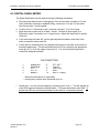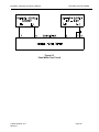
1
MODEL COP-D/DC and COP-D/RMS
PORTABLE DC & RMS CURRENT METERING
Installation, Operation and Service Manual
Manual Item No. 041663
Rev. J
DynAmp, LLC
3735 Gantz Road
Grove City, Ohio 43123 USA
Phone +1 614.871.6900
Fax +1 614.871.6910
www.dynamp.com
[email protected]
Installation, Operation and Service Manual
COP-D/DC and COP-D/RMS
This Page is Intentionally Blank
© 2012 DynAmp, LLC
041663 J
Page ii
Installation, Operation and Service Manual
COP-D/DC and COP-D/RMS
DynAmp, LLC WARRANTY
Items and components manufactured by Seller for permanent installation are warranted for two (2)
years from the date of shipment.
Items and components manufactured by Seller for portable and temporary use in more than one
location are warranted to be free from defects in material and workmanship for a period of eighteen
(18) months from the date of shipment.
Items and components not manufactured and resold by Seller are warranted by their manufacturer.
Warranty repair shall be, at DynAmp’s option, in the form of repair or replacement of the defective
items or components. Concerning warranty repairs, DynAmp will be responsible for DynAmp
provided time, material and transportation costs (shipping or travel). Actual method of warranty
repair / correction will be determined by DynAmp at DynAmp’s sole option. Such warranty repair
shall constitute a fulfillment of all DynAmp, LLC liabilities in respect to said items and components. In
no event shall DynAmp, LLC be liable for consequential damages.
Information in this document is subject to change without notice.
© 1999, 2000, 2001, 2002, 2004, 2010 , 2012 DynAmp, LLC. All rights reserved.
Reproduction for purposes other than operation and service without written permission of DynAmp, LLC is
strictly forbidden.
This manual includes detailed drawings, installation, operation, service and maintenance. Users should
evaluate the information in the manual and their particular application. DynAmp assumes no liability for any
incidental, indirect, or consequential damages arising fro the use of this documentation.
While all information presented is believed to be reliable and in accordance with accepted engineering
practices, DynAmp makes no warranties as to the completeness of the information.
© 2012 DynAmp, LLC
041663 J
Page iii
Installation, Operation and Service Manual
COP-D/DC and COP-D/RMS
This Page is Intentionally Blank
© 2012 DynAmp, LLC
041663 J
Page iv
Installation, Operation and Service Manual
COP-D/DC and COP-D/RMS
Hazard Warning!
Use of the equipment in a manner not specified by the manufacturer can
impair the protection provided within.
DynAmp does not assume liability for the customer’s failure to comply
with the rules and requirements provided in this manual.
GENERAL
This equipment is designed for use where the operator is either totally
electrically isolated or essentially at the same potential as the bus. Ignoring
the warnings can result in severe personal injury or equipment damage.
To avoid the risk of electrical shock, the safety instructions and guidelines
in this manual must be followed. The electrical specifications must not be
exceeded and the unit must be used according to directions provided.
HAZARDOUS
VOLTAGE
Symbol Identification:
General definitions of safety symbols used on equipment and in manual.
Caution/Warning: Refer to accompanying documents for instructions.
© 2012 DynAmp, LLC
041663 J
Page v
Installation, Operation and Service Manual
COP-D/DC and COP-D/RMS
This Page is Intentionally Blank
© 2012 DynAmp, LLC
041663 J
Page vi
Installation, Operation and Service Manual
COP-D/DC and COP-D/RMS
DynAmp, LLC Customer Support
For further assistance, contact DynAmp Customer Support at:
Americas:
Telephone: +1 614.871.6900
Fax:
+1 614.871.6910
8:00 AM to 5:00 PM USA Eastern Time
From first Sunday in November to second Sunday in March – 13:00 GMT to 22:00 GMT
From second Sunday in March to first Sunday in November – 12:00 GMT to 21:00 GMT
Europe:
Telephone:
+41 22.706.1446
Fax:
+41 22.706.1311
8:30 AM to 5:00 PM Central European Time
From last Sunday in October to last Sunday in March – 7:30 GMT to 16:00 GMT
From last Sunday in March to last Sunday in October – 6:30 GMT to 15:00 GMT
After Hours Critical Service Emergency:
Telephone:
+1 614.871.6906
5:00 PM to 8:00 AM USA Eastern Time
From first Sunday in November to second Sunday in March – 22:00 GMT to 13:00 GMT
From second Sunday in March to first Sunday in November – 21:00 GMT to 12:00 GMT
Central e-mail:
[email protected]
DynAmp web:
www.dynamp.com
© 2012 DynAmp, LLC
041663 J
Page vii
Installation, Operation and Service Manual
COP-D/DC and COP-D/RMS
This Page is Intentionally Blank
© 2012 DynAmp, LLC
041663 J
Page viii
Installation, Operation and Service Manual
COP-D/DC and COP-D/RMS
REVISION PAGE
Page
Rev
all
2,3,4
25,26
iii,1,7
27
i,25
all
New
Rev A
Rev B
Rev C
Rev D
Rev E
Rev F
25
all
Rev G
Rev H
First Issue
Added voltage isolation & temp. spec.
Spare Parts List
Inserted Hazard Warning page and Safety Section I
Revise Spare Parts List (Reset Switch)
Warranty statement & Communications
Updated to current format
Updated drawing list – removed 26B100527 and
replace with 26B107083
Update to DynAmp, LLC
all
Rev I
PAR 10245 – Handling & Storage, ECR 1440Calibration Intervals / New Manual Format
01/10
25
Rev J
ECO 3270 – Update Drawing List removed 26B107083
replace with 26A109281
04/12
© 2012 DynAmp, LLC
041663 J
Revision Summary
Date
03/97
08/97
08/97
09/99
09/99
02/00
03/01
06/02
12/04
Page ix
Installation, Operation and Service Manual
COP-D/DC and COP-D/RMS
This Page is Intentionally Blank
© 2012 DynAmp, LLC
041663 J
Page x
Installation, Operation and Service Manual
COP-D/DC and COP-D/RMS
TABLE OF CONTENTS
1. SAFETY
1
1.1 OVERVIEW ..................................................................................................................... 1
2. HANDLING AND STORAGE
1
3. DESCRIPTION
3
3.1 GENERAL ....................................................................................................................... 3
3.2 METER UNIT ................................................................................................................... 3
3.3 MEASURING HEAD ........................................................................................................ 4
4. SPECIFICATIONS
5
5. ENVIRONMENTAL AND SPECIAL CONSIDERATIONS
7
5.1
5.2
5.3
5.4
GENERAL ....................................................................................................................... 7
MECHANICAL ................................................................................................................. 7
ELECTRICAL................................................................................................................... 7
SAFETY........................................................................................................................... 7
6. CONTROLS AND PRINCIPALS OF OPERATION
6.1
6.2
6.3
6.4
6.5
6.6
9
CONTROLS AND INDICATORS ...................................................................................... 9
OPERATION ................................................................................................................. 10
USING DIGITAL READOUT .......................................................................................... 11
REMOVING / INSTALLING BATTERY PACK ................................................................ 12
CHARGING BATTERIES ............................................................................................... 12
SPARE BATTERY PACK ............................................................................................... 12
7. CALIBRATION
7.1
7.2
7.3
7.4
7.5
13
GENERAL ..................................................................................................................... 13
CALIBRATION INTERVALS .......................................................................................... 13
CALIBRATION BUS ....................................................................................................... 13
TEST BUS FABRICATION............................................................................................. 14
CALIBRATION PROCEDURE ....................................................................................... 14
8. TROUBLESHOOTING AND REPAIR
8.1
8.2
8.3
8.4
8.5
19
GENERAL ..................................................................................................................... 19
MEASURING HEAD ...................................................................................................... 19
BATTERY PACK AND CHARGER ................................................................................. 19
METER UNIT ................................................................................................................. 20
DIGITAL PANEL METER ............................................................................................... 21
© 2012 DynAmp, LLC
041663 J
Page xi
Installation, Operation and Service Manual
COP-D/DC and COP-D/RMS
9. SERVICE ASSISTANCE
23
9.2 SPARE PARTS ORDERS - ROUTINE OR EMERGENCY.............................................. 23
9.3 RECOMMENDED SPARE PARTS ................................................................................. 24
10. DRAWINGS
25
TABLE OF FIGURES AND TABLES
FIGURE
TITLE
PAGE
Figure 6.1 Proper wear of the COP-D ...................................................................................... 10
Figure 7.1 Typical Test Coil ...................................................................................................... 14
Figure 7.2 Test Coil Assembly.................................................................................................. 15
Figure 7.3 Test Coil Circuit Diagram ........................................................................................ 15
Figure 8.1 Battery Pack Connector Wiring Diagram ................................................................. 19
Figure 8.2 Charger Cable Connector Wiring Diagram .............................................................. 20
Table 4.1 Specifications ............................................................................................................ 5
Table 4.1 Specifications (cont.) ................................................................................................. 6
Table 9.1 Spare Parts List ....................................................................................................... 24
Table 10.1 Drawing List........................................................................................................... 25
© 2012 DynAmp, LLC
041663 J
Page xii
Installation, Operation and Service Manual
COP-D/DC and COP-D/RMS
1. SAFETY
1.1 OVERVIEW
The Model COP System is intended for use where the operator is either totally electrically
isolated or essentially at the same potential as the bus. Ignoring the operating precautions
and warnings can result in severe personal injury or equipment damage. The following are
general guidelines that should be followed when using the meter unit and head.
•
The operator must be a qualified technician who is familiar with the warnings and the
instructions of this manual.
•
Always follow all local and plant safety procedures.
•
Hazardous potentials may exist in the vicinity of the desired current measurements.
Use locally approved safety procedures when working near these hazardous potentials.
•
Always use appropriate gloves and/or equipment specifically approved for hazardous
voltages when working around hazardous potentials.
•
Do not place the equipment in the rain, or under water, or submerge any part of the
head or meter unit.
•
Use of the equipment in a manner not specified by the manufacturer can impair the
protection provided.
DynAmp does not assume liability for the customer’s failure to comply with the rules and
requirements provided in this manual.
© 2012 DynAmp, LLC
041663 J
Page 1
Installation, Operation and Service Manual
COP-D/DC and COP-D/RMS
This Page is Intentionally Blank
© 2012 DynAmp, LLC
041663 J
Page 2
Installation, Operation and Service Manual
COP-D/DC and COP-D/RMS
2. HANDLING AND STORAGE
DynAmp products are engineered and manufactured for use in industrial environments.
However, they contain sensitive electronic and mechanical components which may be
damaged and fail if not handled and stored properly. All products must be handled and
stored with the same care as any precision measurement instrument. Severe bumps or
jolts may damage internal parts and cause malfunction or premature failure. DynAmp
products are designed and assembled with conformal coating, shock mounting, and
environmental seals, when appropriate or when specified. However, this protection
requires that the product must be properly installed and operational before the protection is
fully functional. Therefore, adequate protection from humidity, shock, and temperature
must be provided during handling and storage prior to installation.
The handling and storage of equipment must be sufficient to meet the storage temperature
and humidity specifications of the product and to prevent any condensation or contact with
water or any other liquid. The storage location and container or crate must provide
adequate protection from precipitation (rain, snow, ice) and direct water contact. Adequate
shelter must be provided to prevent the accumulation of precipitation (rain, snow, ice) and
water which can lead to the deterioration or failure of shipping containers or crates and
cause water ingress. Storage in coastal or industrial areas subject to salt-laden or
corrosive air or areas of wind-driven sand or other abrasive dust must be adequate to
prevent the deterioration or failure of shipping containers or crates and cause ingress.
Frequent inspection of storage areas and storage containers or crates is required to ensure
proper storage conditions are being maintained.
If the shipping container or crate is opened and/or the equipment is removed for inspection
prior to installation, the equipment must be repackaged in the original undamaged
container or crate in the same manner as it was shipped to prevent environmental damage
or placed in a storage location that meets the required environmental and storage
conditions.
General product storage temperature and humidity requirements:
Storage Temperature:
-40 to 70 C
-40 to 158 F
Storage Humidity:
60%, non -condensing
DynAmp, LLC does not assume liability for the customer’s failure to comply with handling
and storage requirements.
For further assistance, contact DynAmp customer support.
© 2012 DynAmp, LLC
041663 J
Page 1
Installation, Operation and Service Manual
COP-D/DC and COP-D/RMS
This Page is Intentionally Blank
© 2012 DynAmp, LLC
041663 J
Page 2
Installation, Operation and Service Manual
COP-D/DC and COP-D/RMS
3. DESCRIPTION
3.1 GENERAL
The DynAmp, LLC Model COP-D Digital Ammeter provides a clamp-on, non-contacting dc
current or dc coupled rms measuring capability (includes ac rms). Ranges are 0 to 2kA, 0
to 20kA and 0 to 10kA, 0 to 100kA. The dc version is model COP-D/DC (item number
041601 for 20kA F.S., and number 041603 for 100kA F.S.) and the ac rms version is model
COP-D/RMS (item number 041602 for 20kA F.S., and number 041604 for 100kA F.S.).
This manual also refers to a COP-D, 2 to 20kA that has an analog output (item number
041605). The COP system item given only refers to the 120Vac model. Digital readout,
lightweight, easy portability, and rechargeable batteries are prominent features. A variety
of choices in clamp-on measuring head styles, sizes, and handle lengths permits matching
the COP-D meter and head combination to meet the desired measurement requirements.
Each Model COP-D consists of the following components:
•
Measuring head
•
Meter unit
•
Rechargeable battery pack
•
Two carrying straps
•
Battery charger
The battery pack plugs into and fastens to the rear of the meter unit to make an integral
assembly. The carrying straps clip to rings on the meter unit. The measuring head has a
coiled cable, which plugs into a mating connector on the meter unit. The battery charger
plugs directly into a conventional 120 Vac, 50/60 Hz outlet, and has a 3-foot cable and
connector for plug-in to the battery pack. The battery pack provides approximately 20 to 24
hours of meter use, and may be recharged either on or off the meter unit. (For safety
considerations, the meter unit is not intended to be operational during recharging.) A spare
battery pack, if included, ensures that the meter will be available for use at all times.
3.2 METER UNIT
The Meter Unit has two measurement ranges, 0 to 2kA and 0 to 20kA, or 0 to 10kA and 0
to 100kA and utilizes a digital readout. An extremely sensitive integrator circuit provides
the high measurement accuracy of the unit. The digital readout permits resolutions of up to
±1 ampere and ±10 amperes on the 2kA and 20kA ranges, respectively. Due to the
sensitivity of the integrator circuit, an external DRIFT ADJUST control is incorporated to
immediately compensate for any factors (such as ambient temperature changes) that may
affect the readout.
The model COP-D/RMS can be used to read dc as well as ac rms signals. There is one
thing to keep in mind when using this model for measuring dc. The reading indicated will
not be dc average as in the COP-D/DC, but it will be the rms value of the dc plus ac
components of the measured current.
© 2012 DynAmp, LLC
041663 J
Page 3
Installation, Operation and Service Manual
COP-D/DC and COP-D/RMS
3.3 MEASURING HEAD
The measuring heads are constructed from high impact, high temperature, non-conducting
molding compound. The standard heads are available in many sizes of rectangles. They
range from a 5 x 5 inch inside dimension to a 17 x 17 inch inside dimension. The X and
the Y dimensions may be vastly different depending upon the size of your bus to be
measured. Consult the DynAmp, LLC factory as to the specific dimensions of standard
heads. The head handles are available in 2, 4, and 6 foot lengths for all standard heads.
The measuring heads are also available without handles.
To ensure long and useful operation:
•
Do not rub the measuring head against sharp or abrasive objects.
•
Close clamping jaws gently.
•
Do not drop or jar the head assembly or metering chassis.
© 2012 DynAmp, LLC
041663 J
Page 4
Installation, Operation and Service Manual
COP-D/DC and COP-D/RMS
4. SPECIFICATIONS
The specifications of the COP-D/DC and COP-D/RMS are given in table 4.1
TABLE 4.1 SPECIFICATIONS
Measurement ranges:
0 to ±2kA (digital readout to ±1.999)
0 to ±20kA (digital readout to ±19.99)
or
0 to ±10kA (digital readout to ±10.00)
0 to ±100kA (digital readout to ±100.0)
Analog output (See Note 1)
2.000V at full scale
Overall accuracy:
±2.5% of full scale (model COP-D/DC)
±3.0% of full scale (model COP-D/RMS)
Linearity error (max.):
±1.0% of full scale (model COP-D/DC)
±3.0% of full scale (model COP-D/RMS for sine wave)
Position error (max.):
Variation in position of measuring head relative to bus yields maximum error of ±1.5% of
full scale.
Stray field error (max.):
An identical bus and field 6 inches away yields error of less than ±1.5% of full scale.
Drift-rate error:
Within a 30-second interval after routine drift adjustment, maximum error due to drift will be
±1.0% of full scale.
© 2012 DynAmp, LLC
041663 J
Page 5
Installation, Operation and Service Manual
COP-D/DC and COP-D/RMS
TABLE 4.1 SPECIFICATIONS (CONT.)
Temperature:
-4°F to 130°F (-20°C to 55°C)
Isolation (System):
30Vac or 60Vdc peak (See Note 2)
Battery pack:
Usage per full charge: 20 - 24 hours nominal
Recharging time: 3 - 4 hours nominal
Total life:
6 - 8 hours after complete discharge.
200 - 500 recharge cycles.
Battery charger input voltage: 120 V or 240 V ac, 50/60 Hz.
Meter unit weight with battery: 4.5 lbs.
Measuring head:
Measurement range, max. kA
See Note 3
Aperture dimensions (in.)
Consult factory
Handle length (in.)
Consult factory
Cable length (in.)
72
Weight (pounds)
Varies with head
Note 1:
Optional output.
Note 2:
The Model COP System is intended for use where the operator is either totally
electrically isolated or essentially at the same potential as the bus.
Note 3:
Maximum measurement range is limited only by the size of the bus that the head
can encompass, and the maximum range of the meter unit the head is used
with. The meter unit must be calibrated for the model and size of measuring
head it is to be used with.
© 2012 DynAmp, LLC
041663 J
Page 6
Installation, Operation and Service Manual
COP-D/DC and COP-D/RMS
5. ENVIRONMENTAL AND SPECIAL CONSIDERATIONS
5.1 GENERAL
The COP-D is a precision instrument; as such, it should be handled with the care normally
associated with high-accuracy electronic equipment.
5.2 MECHANICAL
Materials comprising the measuring head have been selected to protect components
internal to the structure. Consequently, care should be exercised when closing the
measuring head and when placing it around a conductor. Although the head housing is a
tough fiberglass-filled plastic it will not withstand repeated jarring, or rubbing against sharp,
abrasive surfaces.
5.3 ELECTRICAL
The meter unit offers excellent long-term electronic and temperature stability due to the use
of high-quality components. Electrically, there should be no significant changes in
operating parameters over an extended period of time. In event that calibration does
appear necessary, refer to Calibration section in this manual.
5.4 SAFETY
The Model COP System is intended for use where the operator is either totally electrically
isolated or essentially at the same potential as the bus. Ignoring the operating precautions
and warnings can result in severe personal injury or equipment damage.
© 2012 DynAmp, LLC
041663 J
Page 7
Installation, Operation and Service Manual
COP-D/DC and COP-D/RMS
This Page is Intentionally Blank
© 2012 DynAmp, LLC
041663 J
Page 8
Installation, Operation and Service Manual
COP-D/DC and COP-D/RMS
6. CONTROLS and PRINCIPALS OF OPERATION
6.1 CONTROLS AND INDICATORS
All controls and indicators described are on the meter unit unless stated otherwise.
1. DRIFT ADJUST Control: This 10-turn potentiometer is used to stabilize drifting of the
digital readout. The control LOCK ring must be unlocked to adjust the knob, and
relocked after adjustment.
2. FUNCTION SELECTOR Switch: The OFF position disconnects all circuitry from the
batteries, and should be used when the meter is stored or when not in use for 15 - 20
minutes or longer. The BATTERY TEST position provides a check of battery condition
as indicated by LOW lights. DRIFT position is used in conjunction with DRIFT ADJUST
to stabilize any drifting of the digital readout. The (2kA and 20kA) or (10kA and 100kA)
positions are the full-scale ranges for measurement of bus current.
3. RESET Toggle Switch: The RESET switch is spring-loaded to the center (inactive)
position. Momentarily holding the switch toggle left or right resets the digital readout to
zero.
4. Digital Readout: The LED display reads from 0.000 to 1.999 for the 2kA range, and
from 0.00 to 19.99 for the 20kA range, regardless of polarity. This display will include a
sign ("-") to the left of the numerals when the measurement is negative. The model
COP-D/RMS will always read positive. The polarity of the readout is dependent on the
orientation of the measuring head when clamped around the bus, and will be positive
(no sign) if the red dot on the head "faces" the positive bus supply source.
5. 1 LOW and 2 LOW Indicators (LED's): These indicate a low battery condition if
illuminated when the FUNCTION SELECTOR switch is in the BATTERY TEST position.
6. ALTERNATE BATTERIES Switch: (On battery pack). Reverses the uneven load
arrangement on the two batteries in the pack, to obtain maximum use before
recharging is required.
7. ANALOG OUTPUT (Optional): An analog output of .200V at full scale is available at
terminals 1 & 2(+) and 3 & 4 (-) of the output connector on the right side of the unit.
© 2012 DynAmp, LLC
041663 J
Page 9
Installation, Operation and Service Manual
COP-D/DC and COP-D/RMS
6.2 OPERATION
The procedure for proper setup and operation of the COP-D Digital Ammeter is as follows:
a. Clip the carrying strap to the meter. One strap or both straps may be used. Figure 6.1
illustrates how both are used to provide the most comfort and least fatigue.
Figure 6.1
Proper wear of the COP-D
b. Connect the measuring head cable to the mating connector on the meter side.
c. Turn the FUNCTION SELECTOR switch to BATTERY TEST. Test is satisfactory if
neither LOW light comes on. If either light illuminates, reverse the position of the
ALTERNATE BATTERIES switch. If either light is "on", recharge the battery pack; if
both lights are "off", proceed with step d.
Note: If the batteries have been fully discharged, neither of the LOW lights can come on
and the battery test will have appeared to be satisfactory. When the DRIFT position is
selected the digital readout will be blank. If these conditions exist, recharge the battery
pack for 6-8 hours (or longer, if needed).
d. Adjust for minimum drift of the digital readout as follows (the adjustment is made to
stabilize the readout at any given value, rather than to obtain a zero readout):
1) Close the measuring head (NOT around a bus or conductor). DO NOT move the
head during the drift adjustment. For best results, lay the head down on a flat surface
before making this adjustment.
2) Turn the FUNCTION SELECTOR switch to DRIFT.
3) Hold the RESET toggle left or right until the readout is zeroed.
4) Loosen the DRIFT ADJUST lock ring (turn CCW).
© 2012 DynAmp, LLC
041663 J
Page 10
Installation, Operation and Service Manual
COP-D/DC and COP-D/RMS
5) Observe digital readout polarity and value. If readout is becoming more positive, turn
DRIFT ADJUST in a CW direction; if readout is becoming less positive (or going more
negative) turn DRIFT ADJUST in the CCW direction. Continue adjustment until
readout rate of change slows and is eventually stopped at any given value (except
1999). NOTE: The model COP-D/RMS will not respond in this manner. CW or CCW
movement will not necessarily correspond to a meter direction of plus or minus
respectively.
6) Tighten DRIFT ADJUST lock ring, observing that adjustment is not changed.
7) Operate RESET to zero readout.
e. Turn FUNCTION SELECTOR to desired measurement range (2kA or 20kA) or (10kA or
100kA).
f.
With measuring head closed and off the bus, operate RESET to zero readout, just prior to
making measurement. Open the measuring head and place it around the bus. Close the
measuring head and promptly note value and polarity of readout. When the measuring
head is placed around the bus such that the red dot "faces" the positive bus supply
source, the reading will be positive. (If the "-" sign is on, it is not necessary to take
another reading with the measuring head reversed. The readout valued will be identical
in either case.) See "Using Digital Readout" below for additional details on measurement
technique.
g. To ensure maximum accuracy, zero the readout with the RESET switch before each
measurement. This should always be done with the head completely closed and off the
bus. (It is not necessary to reset the meter for each measurement, providing the drift rate
is well adjusted.)
h. During a series of measurements, periodically check for drift of the readout just after
RESET. When the rate of change of the least significant (right-hand) digit is more than
one unit per second, repeat the drift adjust procedure in step d.
i.
During continuous use, recheck the batteries about once per hour, particularly if the
"charge status" of the battery pack is unknown.
j.
Turn the FUNCTION SELECTOR switch to OFF to conserve battery power when the
meter is not going to be used for 15 - 20 minutes or longer, when the meter is being
stored, or when the battery pack on the meter is being recharged.
6.3 USING DIGITAL READOUT
Due to the high resolution of the digital readout, very small percentage changes in bus
current will cause the least significant digit to change so rapidly that it cannot be read. This
condition may frequently occur, and should not be confused with excessive drift. Also, the
condition does not significantly affect accuracy. For example, when in the 2kA range,
disregarding the right-hand digit and using only the three readable left-hand digits,
resolution will be within ±10 amperes.
Example: for 1.53?; this reading yields a ±0.65% accuracy.
The same accuracy would be obtained for a reading of 15.3? on the 20kA range.
However, to achieve this accuracy it may be necessary to observe the readout for several
seconds to determine which tens digit is predominant. For example, if during observation
the changing readout shows 1.52?, 1.53?, 1.54?, 1.55?, 1.54?, 1.53?, 1.53?, 1.52?, 1.53?,
the measured value should be recorded as 1.530kA. A relatively stable current will thus
© 2012 DynAmp, LLC
041663 J
Page 11
Installation, Operation and Service Manual
COP-D/DC and COP-D/RMS
usually be readable within ±10 amperes on the 2kA range, and ±100 amperes on the 20kA
range.
A constantly changing current can also be monitored with reasonable accuracy by
observing just the "ABC" digits where the readout is ±A.BCD or ±AB.CD and D is changing
too fast to read. If the C digit is also changing too fast to read, the A and B digits will still
provide sufficient information to monitor approximate current value, and direction and rate
of change. The length of time and degree of change to be observed will be up to the
operator to determine.
6.4 REMOVING / INSTALLING BATTERY PACK
Electrical connection of the battery pack to the metering unit is made by fixed mating
connectors on each unit. The pack is secured by two lever-action fasteners on the
metering unit. To remove the pack, release both fasteners and then gently work the pack
connector free of the metering connector. Reverse the procedure to install the pack, using
care to properly mate the connectors and the side fasteners.
6.5 CHARGING BATTERIES
Connect the battery charger output cable connector to the mating connector on the rear of
the battery pack. Plug the charger directly into a conventional 120 V ac, 50-60 Hz outlet.
Recharge battery pack 3 to 4 hours if low batteries are routinely detected by the battery
test. Recharge 6 to 8 hours if the batteries are completely discharged. Completely
discharged batteries will be indicated by the following:
LOW lights do not come on during battery test.
Digital readout does not illuminate when the FUNCTION SELECTOR switch is in DRIFT,
(2kA, or 20kA) or (10kA or 100kA) positions.
Note: The battery charger design prevents overcharging of the batteries.
If the unit is used almost daily then it is recommended the unit be continuously charged
when not in use. Charging may be continuous without damage to the charger or battery
pack. The battery pack may be charged either on or off of the metering unit. If left on the
metering unit the FUNCTION SELECTOR should normally be OFF during recharging.
6.6 SPARE BATTERY PACK
Use of a spare battery pack is recommended to ensure that the meter unit is always
available for use. The recommended procedure is to recharge one pack during the time
the other pack and the metering unit are in use. After use of the meter is completed,
interchange the two packs. Repeat this process for each shift that the meter is used.
© 2012 DynAmp, LLC
041663 J
Page 12
Installation, Operation and Service Manual
COP-D/DC and COP-D/RMS
7. CALIBRATION
7.1 GENERAL
Due to the strict requirements for a proper calibration setup in the user's facility, it is
recommended that the meter and measuring head be returned to the factory for calibration,
once it has been suspected or known that measurement accuracy is not within limits.
However, accurate calibration results can be achieved by the user if the following
conditions and procedures can be met.
7.2 CALIBRATION INTERVALS
DynAmp does not specify required intervals of calibration for its products.
The end user of the product is responsible for identifying the appropriate interval between
calibrations. The intervals should be determined based on the following factors:
•
Requirements of a Quality Management System
•
Accuracy and permissible limits of errors
•
Purpose and usage
•
Experience with similar products
•
Manufacturer's recommendations
•
Stability of the product
•
Past history
•
Other characteristics of the product
Reference: "ISO/IEC 17025:2005, General requirements for the competence of testing and
calibration laboratories" and Laboratory Accreditation Bureau "Guidance for Documenting
and Implementing ISO/IEC 17025:2005 and Laboratory Guidance."
As a guideline, DynAmp recommends a 24 month interval of calibration for all permanently
installed products and a 12 month interval of calibration for all products used in portable
applications.
7.3 CALIBRATION BUS
An actual bus can be used as the calibration standard, providing (1) that the current is
accurately known, (2) the current level is very stable, and (3) the area where the calibration
is done is free of stray magnetic fields of significant magnitude or varying intensity. Also,
for best results, a current level in the range of 60% to 95% of full-scale current should be
used for calibrating the COP meter unit on each current range (95% would be best).
Lacking availability of the bus (in an area free of stray fields), a test bus can be fabricated
as described in this section. Use of a fabricated test bus will also require an accurately
metered and adjustable constant voltage, variable-current dc power source. For the test
bus described herein, the power source rating should be one of the following: 150 V dc, 0
to 10 A; 80 V dc, 0 to 20 A; or 40 V dc, 0 to 40 A. Sources with other ratings can be used
but will require a test bus design different than described.
© 2012 DynAmp, LLC
041663 J
Page 13
Installation, Operation and Service Manual
COP-D/DC and COP-D/RMS
7.4 TEST BUS FABRICATION
Refer to Figure 7.1 to make up the test bus. Approximately 6200 feet of copper magnet
wire will be required. The method used to connect the four coils will depend on the rating
of the power source available. As stated before, other designs may be used so long as the
total current can be calculated and controlled.
7.5 CALIBRATION PROCEDURE
The following procedure assumes use of the fabricated test bus, bus currents of 1000 and
10,000 amperes, and you are calibrating a 2-20kA meter unit. (Change test stated values
in the procedure where appropriate, for other bus current values and meter units.)
Note: Calibrations should be conducted in an area as free as possible from stray magnetic
fields, for best accuracy. Medium to strong fields, or fields of varying intensity, can prevent
proper calibration.
LE A D S
TA P E
STEP 1. Make 4 coils, 250 turns each, from
No. 14 AWG enameled copper magnet wire
tightly wound on 18" square form. Remove
from form and tape windings as shown. Allow
about 1550 feet of wire per coil. Resistance of
each coil will be approximately 3.75 ohms.
T Y P IC A L
C O IL
Figure 7.1
Typical Test Coil
© 2012 DynAmp, LLC
041663 J
1 8"
1 8"
Page 14
Installation, Operation and Service Manual
-
4
-
TAPE
+
+
+
-
+
1
COP-D/DC and COP-D/RMS
3
STEP 2. Assemble coils as shown and tape
common sides together. The common side of
the assembly is the "bus" around which the
measuring head is placed for calibration. (Set
assembly on non-conducting surface for
operation.)
-
2
90
Figure 7.2
Test Coil Assembly
STEP 3. Depending on the dc power source available, connect the coils in series (A),
series-parallel (B) or parallel (C). Refer to the coil diagrams below.
Figure 7.3
Test Coil Circuit Diagram
© 2012 DynAmp, LLC
041663 J
Page 15
Installation, Operation and Service Manual
COP-D/DC and COP-D/RMS
To calibrate the meter unit, proceed as follows.
NOTE: The following steps make reference to circuit common. Use the proper end of
resistor R24 for this point. Refer to the p.c. board schematic and assembly diagrams.
a. Remove the battery pack from the rear of the meter unit.
b. Remove the back plate of the meter unit (four flat-head screws).
c. Reconnect the back plate to the battery pack. Sufficient lead length is available to do
this.
d. With the measuring head connected to the meter unit, set the FUNCTION SELECTOR
switch to BATTERY TEST.
e. If either LOW lamp is on, recharge the battery pack. If both lamps are off, continue
with step f.
f.
Turn the FUNCTION SELECTOR to DRIFT and adjust for minimum drift as described
in Section IV, Controls and Principals Of Operation.
g. Attach a dc millivolt meter to the output of U1 (pin 6 to circuit common). Hold the
RESET switch closed. Adjust P4 for the best zero reading. Remove meter.
h. If U2 is not installed, go to the next step. Again, hold the reset switch closed while
adjusting P5 for the best zero reading on the COP meter face.
i.
If U3 is not installed, go to the next step. Attach the dc millivolt meter to the output
connector (pin 1 to pin 4). Again, hold the reset switch closed while adjusting P6 for the
best zero reading. Remove meter.
j.
Recheck drift adjustment, step f.
k. Turn FUNCTION SELECTOR to the 2kA range and momentarily operate RESET
switch to zero output.
l.
Adjust the test bus current source to obtain a bus current of 1000 amperes.
m. With measuring head closed and NOT on the bus, operate RESET.
n. Place the head around the bus, close and note meter unit readout:
1) If the readout is 1.000 ±0.005 proceed to step q.
2) If the readout is not within limits, adjust P2 as required to obtain a readout of 1.000
±0.005. The current must be stable at 1000 amperes during this adjustment. If the
adjustment is made satisfactorily, proceed to step s. If adjustment of P2 will not
bring the readout up to 1.000, proceed to step o.
o. Remove the head from the test bus and close. Turn COARSE adjustment P3
approximately 5 turns CCW.
p. Operate RESET, then again place head around test bus. The reading should be
somewhat higher than obtained in step l-2.
q. Repeat steps m and n until a readout of approximately 1.100 (or 10% greater than the
bus current) is obtained. (Note: when the head is on the test bus it is not possible to
change the readout by adjustment of P3).
r.
With the reading high as established in steps m through o, readjust P2 to obtain a
readout of 1.000 ±0.005. This completes calibration of the 2kA range.
© 2012 DynAmp, LLC
041663 J
Page 16
Installation, Operation and Service Manual
COP-D/DC and COP-D/RMS
s. For the 20kA range calibration a test bus current of 10,000 amperes is preferred, but
other levels can be used if necessary. In the following, a current of 10,000 amperes is
assumed, with a desired meter readout of 10.00.
t.
With the head OFF of the bus and closed, turn FUNCTION SELECTOR switch to the
20kA range and operate RESET to zero readout. If any drift of readout is evident,
stabilize with DRIFT ADJUST in the usual manner.
u. Adjust the test bus current source to obtain a bus current of 10,000 amperes.
v. With the measuring head closed and NOT on the bus, operate RESET.
w. Place the head around the bus, close and note meter readout:
1. If the readout is 10.00 ±0.05, calibration is satisfactory.
2. If the readout is not within limits, adjust P1 as required to obtain a readout of 10.00
±0.05. The current must be stable at 10,000 amperes during this adjustment. (Do
not make any change in the adjustment of P3 since it affects both ranges and has
already been properly adjusted). When P1 is satisfactorily adjusted, calibration is
complete.
x. Replace meter unit back plate and then replace battery pack. Meter is now ready for
normal use. Turn meter OFF, and disassemble the test setup.
© 2012 DynAmp, LLC
041663 J
Page 17
Installation, Operation and Service Manual
COP-D/DC and COP-D/RMS
This Page is Intentionally Blank
© 2012 DynAmp, LLC
041663 J
Page 18
Installation, Operation and Service Manual
COP-D/DC and COP-D/RMS
8. TROUBLESHOOTING AND REPAIR
8.1 GENERAL
Troubleshooting should begin by isolating the problem to either the measuring head, the
battery pack or charger, or the metering unit. Repair, if indicated, should be accomplished
by a qualified technician or at the DynAmp, LLC factory.
8.2 MEASURING HEAD
Internal failure of the measuring head is a remote possibility but should not be disregarded.
Failure within the interconnecting cable or connector is a more probable trouble source.
Resistance measurements (taken at the pins of the connector cable) within the values
listed below will confirm that the cable conductors and the series-connected coils in the
measuring head are not open or short-circuited. Tap the head firmly and shake the cable
when measuring, to check for the possibility of an intermittent fault. If the measurement is
obviously in error, return the measuring head and meter unit to the factory for repair and
recalibration.
SERIES RESISTANCE, OHMS
STANDARD MODELS (all sizes)
20,000 ±2000
8.3 BATTERY PACK AND CHARGER
To check for a battery pack fault, measure both outputs at the rear connector terminals
(see figure 8.1). The outputs should be ±6.1 V dc or higher with the battery pack off the
meter unit. With the battery pack on the meter unit and the FUNCTION SELECTOR at
BATTERY TEST, both outputs should be ±5.3 V dc or higher. If the readings are low;
either recharging is required, the battery charger is faulty, or the battery pack is faulty. If all
readings are satisfactory, check out the meter unit.
Figure 8.1
Battery Pack Connector Wiring Diagram
Assuming battery voltages were low, check outputs of charger to be ±6.7 ±0.5 V dc at the
pins of the connector on the output cable (see figure 8.2). If charger is faulty refer to
schematic and PCB layout in this manual to initiate repairs, or return the charger to the
factory.
© 2012 DynAmp, LLC
041663 J
Page 19
Installation, Operation and Service Manual
COP-D/DC and COP-D/RMS
Figure 8.2
Charger Cable Connector Wiring Diagram
Assuming battery voltages were low and charger outputs were satisfactory, recharge the
battery pack for at least 8 hours and recheck outputs. (Note: a fully discharged battery
pack can take a considerable period of time to recharge.) If outputs have increased but
are still low, continue charging. A zero output of a battery will usually indicate faulty
internal wiring or a faulty ALTERNATE switch. If after charging the output voltages
measure satisfactory with no load, but are low or rapidly dropping when loaded (BATTERY
TEST position), then it may be time to replace the batteries. The batteries have a lifetime
expectancy of 200 to 500 charge/discharge cycles.
8.4 METER UNIT
When reasonably sure that the measuring head and battery pack or charger are not the
source of trouble, proceed with troubleshooting of the meter unit. Due to the simplicity of
the unit, no explicit procedures are given. Study the schematic, and proceed from the
input, making voltage, continuity, or resistance checks as appropriate. If unable to isolate
the trouble or to make repairs, return all components to DynAmp, LLC to ensure thorough
checkout and proper recalibration with the measuring head supplied.
IMPORTANT NOTE:
The COP printed circuit board is a sensitive instrument and was factory cleaned as to avoid
any surface contaminants that may lead to circuit drift and/or circuit inaccuracy. If
soldering needs to be done, use only solder containing rosin core flux. The board should
only be cleaned with a cleaner such as Sonic Solve or Trichloroethane to be effective.
BE SURE TO READ ALL SAFETY RECOMMENDATIONS CONCERNING THE USE OF
THESE SOLVENTS BEFORE PROCEEDING WITH THE P.C.B. CLEANING!
If repairs to the meter unit are made which involve replacement of the operational amplifier,
RMS converter, related potentiometers and resistors, or if the adjustment of any of P1 thru
P4 is changed, the meter unit must be recalibrated. Refer to Controls and Principals of
Operation section in this manual.
© 2012 DynAmp, LLC
041663 J
Page 20
Installation, Operation and Service Manual
COP-D/DC and COP-D/RMS
8.5 DIGITAL PANEL METER
The Digital Panel Meter can be checked using the following information:
a. Disconnect the digital meter by unplugging it from the connector mounted on it’s rear.
Using a different connector or separate wiring, connect pin 12 to pin 3 of the meter.
Also connect pins 7 and 8 together.
b. Connect 4.9 to 5.1 Vdc power to pin 3 (common) and pin 5 (+V) of the meter.
c. Allow the meter to warm up for at least 1 minute. Connect an input signal (0 to
200mVdc) to pins 3 (common) and 11 (signal input). Adjust this signal level to exactly
190mVdc.
d. If the meter does not read 190, use the gain adjustment located on the back of the
meter to make the meter read 190.
e. Control pins for decimal points in the display are brought out the back of the meter for
external programming. The required decimal point is lit by connecting the appropriate
meter pin (4,5, or 6) to the supply common pin 3. You can test these using the pin
connection designations below.
PIN CONNECTORS
1
2
3
4
5
Analog Gnd
Digital Gnd.
D.P. 1 **
D.P. 10 **
Battery +
6
7
8
9
10
D.P. 100 **
Input HI
Input LOW
Hold *
Dec. Pt., Supply
* Meter will hold when pin 9 is grounded
** Decimal point is active when connected to pin 10
f.
Display test - You may test the display by connecting pin 2 to pin 1. This will activate all
meter LED segments except the decimal points. The meter should then read 1888. To
protect the LEDs, the test function should only be used for 10 seconds maximum.
© 2012 DynAmp, LLC
041663 J
Page 21
Installation, Operation and Service Manual
COP-D/DC and COP-D/RMS
Figure 8.3
Panel Meter Test Circuit
© 2012 DynAmp, LLC
041663 J
Page 22
Installation, Operation and Service Manual
COP-D/DC and COP-D/RMS
9. SERVICE ASSISTANCE
9.1 SERVICE ASSISTANCE
For further assistance, contact DynAmp Customer Support at:
Americas:
Telephone:
+1 614.871.6900
Fax: +1 614.871.6910
8:00 AM to 5:00 PM USA Eastern Time
From first Sunday in November to second Sunday in March – 13:00 GMT to 22:00 GMT
From second Sunday in March to first Sunday in November – 12:00 GMT to 21:00 GMT
Europe:
Telephone:
+41 22.706.1446
Fax: +41 22.706.1311
8:30 AM to 5:00 PM Central European Time
From last Sunday in October to last Sunday in March – 7:30 GMT to 16:00 GMT
From last Sunday in March to last Sunday in October – 6:30 GMT to 15:00 GMT
After Hours Critical Service Emergency:
Telephone:
+1 614.871.6906
5:00 PM to 8:00 AM USA Eastern Time
From first Sunday in November to second Sunday in March – 22:00 GMT to 13:00 GMT
From second Sunday in March to first Sunday in November – 21:00 GMT to 12:00 GMT
Central e-mail:
[email protected]
DynAmp web:
www.dynamp.com
9.2 SPARE PARTS ORDERS - ROUTINE OR EMERGENCY
Requests for spare parts, either in an emergency or for a routine order, should be directed
to "Inside Sales" at DynAmp, LLC during normal hours, if possible, or via any method
shown above for off-hours. When contacting us, please present as much information as
possible the related equipment Model Number and Serial Number; the required part name
and its DynAmp, LLC item number (and other identifying or vendor number(s); and your
time needs. An approved Purchase Order Number should be given with your order.
© 2012 DynAmp, LLC
041663 J
Page 23
Installation, Operation and Service Manual
COP-D/DC and COP-D/RMS
9.3 RECOMMENDED SPARE PARTS
Table 9.1 lists the minimum recommended quantities for spare parts for the COP-D/DC
and COP-D/RMS. As spares are used, replacements should be ordered. Since
continuous operation of high-current measurement equipment is usually essential, stocking
spare parts should be given a high priority.
TABLE 9.1 SPARE PARTS LIST
DESCRIPTION
ITEM NO.
QUAN.
Bracket, reinforcing
01033
1
Spring 2.8”
01781
1
Cable
02119
1
Cable strain relief
02819
1
Bracket, reinforcing part line
02932
1
Cable connector
03282
1
3” Straight module (not used with the 5 x 5 head)
04239
2
Corner module
04240
2
Pot 50k ohms 10T
001085
1
Cable connector
003398
1
Function switch assembly
004864
1
Reset switch
007733
1
OP Amp OP-77
024316
1
P.C. Board assembly
041023
1
Meter
041603
1
Measuring Head
Metering Unit
© 2012 DynAmp, LLC
041663 J
Page 24
Installation, Operation and Service Manual
COP-D/DC and COP-D/RMS
10. DRAWINGS
The following is a list of drawings needed to troubleshoot and calibrate the COP-D/DC and
COP-D/RMS metering units.
TABLE 10.1
DRAWING LIST
DRAWING TITLE
NUMBER
Outline Dimensions, Digital COP Metering Unit
02A109158
System Schematic, Digital COP and Battery Charger
05B108015
PC Board Assembly, Digital COP
26B107804
PC Board Assembly, Battery Charger
26A109281
PC Board Assembly, Digital COP Meter Interface
26A108014
© 2012 DynAmp, LLC
041663 J
Page 25