1
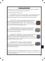
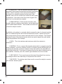
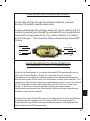
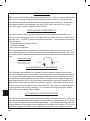
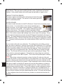
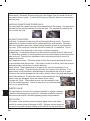
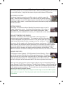
OBD II: WHAT IS IT?
OBD II refers to the On Board Diagnostics generation two. This is a system that has the
ability to test its various components and systems and tell the driver when a fault has
been detected that will cause the vehicle to put out excessive emissions. This system
first became available on passenger cars in the 1995 model year and 1996 for light
trucks with a gross vehicle weight of under 8500lbs.
WHAT CAN THE SYSTEM DETECT?
The system has the ability to detect malfunctions in many engine systems that can
cause excessive emissions. Let’s look at the individual system checks or monitors and
how they work. The OBD II system uses different monitors. These monitors are divided
into three types:
1. Comprehensive Component Monitor
2. Continuous Monitor
3. Non Continuous Monitor
The Comprehensive Component Monitor runs electrical tests on all of the sensors to
ensure that they perform. It tests the sensor range and also does rationality tests. This
test ensures that the sensor output makes sense or are rational when compared to each
other.
NTK Sensor Shown
Gray Wire, Sensor Ground
Probe Tip
Black Wire, Sensor Signal
White Wire, Heater Circuit
Connector
OXYGEN SENSOR SYSTEM MONITOR
The O2 sensors are monitored or checked for proper reference signals and to make
sure that the heater circuit is functioning. O2 sensors that are located before the catalytic converter are tested for high and low voltage thresholds and for switching frequency.
the switching frequency test will count the number of times that the signal voltage goes
beyond the mid point of 450 millivolts during a specified time frame and compares this
figure with the information stored in the vehicles computer. The system will also count
the rich to lean transition and the lean to rich transition. This, again, is checked against
the time stored in the vehicles computer. For universal O2 wiring information, please
see the O2 sensor section of this catalog.
THE CATALYTIC CONVERTER MONITOR
The vehicles O2 sensors are used to determine catalytic converter efficiency. All the oxygen sensors located before the catalytic converter show a voltage pattern on an oscilloscope of a wave form having many peaks and valleys. These peaks and valleys are the
varying voltages of the oxygen sensor signaling rich and lean air/fuel ratios. This type of
wave form is proper for the O2 sensors that are located before the catalytic converter.
472