1
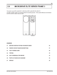
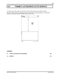
67 4.0 ULTRADRIVE ELITE FRAMES 5, 6 AND 7 FAULT FINDING AND TESTING This section covers 400V models UE-170 to UE-660 and 500V models UE-170D to UE-700D Frame 5: UE-170 to UE-250 UE-170D to UE-250D Frame 6: UE-305 to UE-480 UE-305D to UE-540D Frame 7: UE-575 to UE-660 UE-620D to UE-700D These will be referred to Frames 5, 6 or 7. The voltage range will not be mentioned unless there are specific differences between the 400V and 500V models. 4508-296A : UE-660 : 000000 380-440 VAC -20/+10% 3~ 48-62Hz 660 Amps AC MOTOR SPEED CONTROLLER MODEL SERIAL No. VOLTAGE CURRENT PO BOX 741, NAPIER NEW ZEALAND MANUFACTURED BY 4508299A PDL ELECTRONICS LTD : UE-660 : 000000 380-440 VAC -20/+10% 3~ 48-62Hz 660 Amps MODEL SERIAL No. VOLTAGE CURRENT AC MOTOR SPEED CONTROLLER MANUFACTURED BY PO BOX 741, NAPIER NEW ZEALAND PDL ELECTRONICS LTD PO BOX 741, NAPIER NEW ZEALAND 1999 FREQ PHASE 48 - 62 Hz 3 0 - 400 Hz 3 CURRENT ??? Amps* ??? Amps* SERIAL NO: ????? VOLTAGE INPUT: 380-460 Vac OUTPUT: 0 - 445 Vac MODEL: UE??? Caution: Refer to technical manual PDL ELECTRONICS LTD AC MOTOR CONTROLLER 4508-300A Contents 4.1 BEFORE STARTING TESTING OR SERVICE WORK 68 4.2 PRINTED CIRCUIT BOARD DESCRIPTION 69 4.3 FAULT FINDING GUIDE 71 4.4 TESTING 77 4.5 SOFT POWERING AFTER REPAIR 81 Elite Series Service Manual 4201-230 Rev B57 68 Frame 5 , 6 & 7 4.1 BEFORE STARTING TESTING OR SERVICE WORK 4.1.1 SITE PREPARATION These frame sizes are the most likely to be serviced in place due to their physical size and weight. Many locations where they are mounted will not be ideal for servicing and therefore it is recommended that: 1) The work area in front of the Elite be cleaned. 2) Some flat surfaces are arranged for placement of parts. 3) Provide containers for small items like screws and bolts. Tool Requirements 1 x No.2 Phillips Screw Drivers 1 x No.3 Phillips Screw Drivers 1 x Flat blade 3.5 mm for terminals 2 x 10 mm Ring spanners 2 x 13mm Ring spanners 1 x 3/8 inch ratchet driver 1 x 3/8 inch small extension 1 x 10mm socket 1 x 13mm socket 1 x Category 3 multimeter with ranges to 1000V AC and DC maximum 1 x PDL Soft Power Supply 1 x Isolating Transformer 1kVA 1 x 24Vdc volt power supply, a current limited supply is preferred but a simple plug pack or batteries can be used if it is not available with a lamp in series to limit the current flow to about 2 amps. SAFETY 1) Static safe procedures must be observed. A grounding strap must be worn and earthed. 2) Isolate and lock out the mains supply to the Elite and any low voltage supply that may be in parallel with the control power supply. 3) Allow approximately 5 minutes for the DC bus capacitors to discharge. 4) Open the cabinet door and check the red LED DC bus live indicator is not showing. This is located on the lower right hand side of the control board. This indicates the DC bus is discharged. Note this is only an indicator. Hinge Plate 2 OFF M6 x 16 CW SCREWS TESTING BEFORE STARTING REPAIRS USING FRAME 5 AS AN EXAMPLE 1) Remove the 2 off M5x12 CW screws and remove the bottom front panel. 2) Test between input terminals L1, L2, L3 and L1, L2, L3 to earth, to ensure the supply has been disconnected. 3) Finally test between the +VE and -VE DC bus terminals to ensure the DC bus has fully discharged. EARTH LINK BRAID 2 OFF M6 x 12 CW SCREWS DISPLAY LOOM Frame 5 Cabinet View BOTTOM PANEL RETAINING SCREWS 2 OFF M5 x 12 CW SCREWS 1999 SERIAL NO: ????? VOLTAGECURRENTFREQ PHASE INPUT:380-460 Vac ??? Amps* 48 - 62 Hz OUTPUT:0 - 445 Vac ??? Amps* 0 - 400 Hz3 3 MODEL: UE??? Caution: Refer to technical manual PO BOX 741, NAPIER NEW ZEALAND PDL ELECTRONICS LTD Figure 4.1: AC MOTOR CONTROLLER RATING AND SERIAL LABEL 4508-281A Elite Series Service Manual 4201-230 Rev B57 69 Frame 5, 6 & 7 4.2 PRINTED CIRCUIT BOARD DESCRIPTION Display The Display has three buttons and a 2 by16 character display. It is the user interface for all parameter settings and is common to the Elite Series, for a fault finding guide see section 4.3.3. Control Board The Control board is common to the Elite Series. For a description and a fault finding guide, see section 4.3.4. The Control board accepts all external control inputs and generates output signals. The inputs and outputs include; digital, analogue, fibre optic and Modbus serial communications. A shaft encoder interface and 5V power supply is standard. The Display plugs into the control board. The Control board also has a bidirectional 24Vdc user power supply rated at 500mA. Power Tray The Power tray (Power Electronics Assembly) is made up of a metal support tray, Control board mounting tray and Power board. The Power tray receives power from the DC bus via the DC Supply board. Circuitry included on the Power Tray The main switch mode power supply provides various isolated DC supplies required by the Elite these are: 1) 6 off +17V, 0V, -14V to the Gatedrive board. 2) 28V for the internal fans and Control board. 3) 24V 500mA user power supply (via the Control board). SCR switch mode power supply provides various isolated DC supplies required by the Elite, these are: 1) +8V, 0V, for SCR Gatedrive circuitry and DC Bus discharge control. 2) +15, 0V for switch mode regulation circuitry. The Gatedrive control for the SCRs and DC Bus discharge circuit are also located here. The drive select module plugs into this board. Note the locations are different for the 400V and 500V models. The Power tray is also used as an interface board for the DCCTs and Gatedrive Board to the Control Board. Light emitting diodes (LEDS) located on the Power tray. LED (Green) One for each half phase (6) Actual indication IGBT Gatedrive circuit active. Implication The Elite is running. LED (RED) One for DC Bus indication. Actual indication DC BUS is LIVE. Implication The Elite has power connected. When ordering a replacement Power Tray it will come with the metal support tray and Control Board mounting plate. Elite Series Service Manual 4201-230 Rev B57 70 Frame 5 , 6 & 7 Gatedrive Board Gatedrive Circuits: responds to a fibre-optic signal from the control board via the Power tray and controls the inverter IGBTs. Desat Circuits: monitors the voltage across the IGBTs and turn off the IGBTs in a controlled manner if they become overloaded. On this condition the Desat circuitry also sends a trip signal to the Control board via the fibre-optic link to the Power tray. This signal will trip the Elite and the display will indicate which half phase was overloaded. Snubber Circuits 2 off: protects the IGBTs from damage due to voltage spikes, caused by inductance in the Elite, the motor circuit and the IGBTS rapid switching. Power tray LED indicators are located by the fibre-optic connections. LED (red) One for each half phase Actual indication Implication Transmit fibre OK. The Desat fibre optic driver has condition). power (this is not an indication of a fault it is a normal LED (Green) One for each half phase Actual indication IGBT Gatedrive circuit active. Implication The Elite is running. Power Supply Board Provides power to the power tray and has two LEDs to indicate DC bus voltage is present. Bus Sharing Boards This boards ensures that the DC bus voltage is divided evenly across the DC Bus capacitors. SCR Boards These boards have voltage transient. RFI protection for the Elite and snubbering for the SCRs. They also have a connection to the SCR gate for the Gatedrive signal from the Power tray, and a 10 Amp fuse for the external fans or fan power supply on the 500V models. 500V External Fan Power Supply A 400Vac to 500Vac to 24Vdc linear power supply for the 500V model external fans. Note there are connection points for voltage ranges from 400V to and including 500V. Elite Series Service Manual 4201-230 Rev B57 71 Frame 5, 6 & 7 4.3 FAULT FINDING GUIDE 4.3.1 SUPPLY ISSUES Power supply problems can be misinterpreted as faults in the Elite, some are listed below. Fault 01 LOW Vdc The supply to the Elite is dropping below the switch mode power supply operating level and it is shutting down. This is usually caused by a weak supply or faults in the supply system. Look for motors starting direct on line or other machines drawing high current. For further details see the fault list in section 8 of this manual. Fault 02 HIGH Vdc The supply to the Elite is surging too high. Rapid load changes in the supply system may be at fault. For further details see the fault list in section 8 of this manual. Fault 04 SUPPLY FLT Supply fault (Fault 04) is an indication that the ripple on the DC Bus has exceeded 40Vac. The Elite will trip if this condition is reached and display fault 04 SUPPLY FLT. This can be caused by diode(s) in the rectifier going open circuit, see section 1.4. But is more likely to be caused by 1) The loss of an input phase will increase the ripple on the DC Bus. The Elite can run on two phases up to about half to two thirds of its current rating. At which point the DC Bus filter will not be capable of maintaining the ripple below 40Vac and the Elite will trip. The Display will stay live and the Elite can be reset and will run to about the same current before tripping again. 2) Excessive mains distortion (harmonics) can also cause excessive ripple on the DC Bus. The cause of excessive supply distortion in an industrial situation may be SCR controlled heating equipment, DC drives, current source inverters, and other high current non linear loads. This can occur where backup generators are used which have not been sized correctly relative to the total variable speed drive load (VSD). The total loading of VSDs on a backup generator should be about 60% and the remaining 40% made up of linear loads. 4.3.2 FUSE FAILURE Frames 5 to 7 Elite have a number of fuses for SAFETY backup. Fuse failure is not a normal event, and it usually indicates a more serious fault. Thus the reason for fuse failure should be investigated. A list of fuses, with their locations, possible reasons for failure and suggested corrective actions, follows: Input and DC Bus Fuses The input fuses are located in the lower cabinet and the DC bus fuses are located in the electronics cabinet. Possible reason for failure: Supply surge, age or cyclic stress failure, wrong fuses, fault in supply cable to the Elite, rectifier or inverter fault, motor or motor cable fault. Action: 1) See section 4.1 before starting. 2) Perform a visual inspection for mechanical damage, water entry, or any other possible damage to the system. 3) For new or modified installations, check the wiring is correct as per the Technical Manual 4201-180. 4) Check fuses for correct rating. 5) Disconnect supply cables and test for phase to phase or phase to earth fault. 6) Mark and disconnect the output cables, test the cables and motor for phase to phase and phase to earth fault. 7) Test the Elite for rectifier, inverter or DC Bus faults as per section 4.5.1. 8) If no faults are found the best option is to Soft Power the Elite as per section 4.5. If you consider the fuses failed because of an external issue such as short term overload or cyclic stress, reconnect the Elite, replace the fuses and attempt to run the Elite. Control Board Fuse Located on the Control board. This fuse is in series with the user 24Vdc 500mA power supply accessed via T36 and T37. The user power supply is short circuit protected and will shut down if a short is present in the field control wiring or other device connected to T36 and T37. Elite Series Service Manual 4201-230 Rev B57 72 Frame 5 , 6 & 7 2A 440V Power Tray DC Supply Fuses Fitted on Elite Power Supply Board. Possible reason for failure: Fault in main switch mode power supply on Power tray. Inspect the Power tray for visibly damaged or blackened components. If damaged components exist, replace the Power tray. If there is no visible damage, replace the fuse and repower the Elite. If the fuse blows again, replace the Power tray. WARNING: These fuses must not be replaced with glass fuses (glass fuses will rupture and cause catastrophic damage). Use only the specified ceramic fuse. Action: Replace fuses. If failure persists, replace Power tray. 10A 440V heatsink fan supply fuses Fitted on SCR boards. Possible reason for failure: Supply surge; 400V models external cooling fan fault or for 500V models a fault in the external cooling fan power supply. Action: Check cooling fans or cooling fan power supply. Check varistor on SCR boards for signs of damage, a small dentists style mirror is suitable for this. Elite Series Service Manual 4201-230 Rev B57 73 Frame 5, 6 & 7 4.3.3 DISPLAY 4.3.4 Display Unit Fault Finding Is the screen appearance normal Control board fault finding Yes Put the Elite in commission mode see note 2 No Are there lines of pixels missing CONTROL BOARD Yes Replace the Display Unit Check field control wiring for faults or disconnect it Is 28VDC present on the fan terminals see note 1 No Replace the Power Tray Yes No Are the screen terminations correct see note 1 Re-connect correctly No Note The Display Unit may be permanently damaged Yes Is 24VDC present between T10 & T12 No See Control Board fault finding Has the Control Board had high voltage applied to it Yes No Is 24VDC present on terminals 20 & 21 No Replace the Control Board Yes Yes Is the Display Unit mounted > 3 metres from the Elite Yes Reduce to 3 metres Is 24VDC present on terminals 37 & 36 No Check the field wiring again and replace the 500mA fuse on the Control Board Yes No Replace the Control Board Replace Display Unit 4508-249A Note 1: Terminal 10 - red Terminal 11 - white Terminal 12 - black + screen Note 2: See Elite Series Technical Manual 4201-180 Screens Z to Z1 Figure 4.2: Display Fault Finding Elite Series Service Manual 4508-327A Note 1 The fan terminals are located between the fibre optic connections at the bottom of the Control Board. These are not used in these frame sizes, but still indicate that the Power Tray switch mode power supply is producing the 28Vdc required by the Control Board. Figure 4.3: Control Board Fault Finding 4201-230 Rev B57 74 4.3.5 Frame 5 , 6 & 7 INPUT RECTIFIER The Rectifier is a half controlled bridge that combines DC conversion and the Soft Charge section of the Elite into one stage. The SCR(s) on Line 1 are phase controlled to limit the inrush current due to the DC Bus capacitors when the Elite is powered up, this is termed "Soft Charge". The phase control is continued until the capacitors are fully charged then all SCRs are turned on. Rectifier/Soft Charge failure can be indicated by: Input fuses blowing on power application or display of SUPPLY FAULT, especially on application of load. See section 4.4.1 for supply problems Some Causes of Rectifier Failure Bus Capacitor Failure: Excess current drawn by a shorted capacitors may damage the rectifier. See section 4.3.3. Internal fault in Elite: Failure to a short circuit will cause two input phase fuses to blow. See section 4.3. Fault in supply cable, motor cable or motor. Input supply imbalance: If Line 1 (L1) is low with respect to yellow and blue, the Elite will soft charge the capacitors to 1.414 x the L1 RMS voltage level. When the soft charge is finished, the SCRs on L2 and L3 will be turned on fully applying a higher DC level to the DC bus than is currently there. This can generate sufficient inrush current to damage the input rectifier. Supply voltage exceeding the Elite's rating: The Elite has VDR's to protect against voltage transients, these will not cope with a supply that is constantly above the maximum level the Elite was designed for. The VDR's will fail and the Elite may be damaged also. Soft Charge Failure Failure of the Soft Charge function: Some or all of the SCR's may not respond to a gate signal or the Power tray may not be producing an SCR gatedrive signal. Look for a dislodged cable and test the SCR's as per section 4.4.2. Diode or SCR Failure: If part of the rectifier stage has failed open circuit the Elite may not soft charge and no voltage will appear on the DC bus. Note it is uncommon for semiconductors to fail open circuit. REPLACEMENT SCR'S Replacement SCRs do not require batch matching. 4.3.6 INVERTER DESCRIPTION The inverter consists of insulated gate bipolar transistors (IGBTs) in parallel to achieve the required current rating. Frame size 5 has two IGBTs per half phase, Frame 6 has four and Frame 7 has six. These are in parallel and share evenly the current supplied to the motor. SYMPTOMS OF INVERTER FAILURE 1) Input fuses blowing on power application. 2) DC bus fuses blowing on power application. 3) DESAT fault 08 to 13 constantly on the same phase and polarity. 4) Current limit fault 07, this is a hardware trip to indicate that 220% of rated output current has been reached. For all of the above faults, test the IGBTs as per section 4.4.1. Check the motor and motor cables. If no faults are found, attempt to reset the Elite. If the fault is repetitive on the same phase and polarity check the IGBTs again. If the fault is a DESAT fault and not always on the same phase, the problem is most likely in the Gatedrive board. There is a small possibility that the Power tray may be at fault and since it is the easiest, it is worth replacing it first. U+ HALF PHASE FRAME 5 INVERTOR LAYOUT U V W U- HALF PHASE Figure 4.5 : Elite Series Service Manual 4508-292A IGBT Half Phase Layout 4201-230 Rev B57 75 Frame 5, 6 & 7 Replacing the IGBT The IGBTs are manufactured in batches, and each batch has a unique batch number. The IGBTs from a specific batch are made from the same silicon, therefore their operating characteristics will be the same. Therefore we require that IGBTs in each half phase, be from the same batch. When an Elite is repaired under warranty, the complete half phase must be replaced with the same batch or the warranty will be void. Note: the batch in a half phase does not have to match the batch in another half phase. For example in a Frame 7 it may have transpired that 2 IGBTs are damaged and the other 4 in the half phase test OK with a multimeter. In this situation, PDL or its agent would replace all six IGBTs. Apart from the batch issue, we have found, that while the remaining IGBTs in the half phase may test OK they will have been stressed. The effect on their life span due to the stress cannot be gauged. For these reasons, a repair without full half phase IGBT replacement can not be guaranteed. BATCH NUMBER Figure 4.5: 4.3.7 4508-235A Batch Number DC BUS FILTER The DC Bus filter is comprised of electrolytic capacitors and chokes. The chokes are mounted in series with L1, L2 and L3 and are called line chokes. The filters function is to reduce the harmonic current drawn by the Elite and the ripple on the DC Bus. Excess ripple >40Vac will be detected and displayed as a supply fault, see section 4.3.1 for further details. To achieve the required voltage rating, two capacitors are connected in series. The capacitors are rated at 400V and 450V for the 400V and 500V models respectively. Possible Causes of Failure The definition of capacitor failure is for the capacitance of the capacitor to drop or exceed the manufacturers tolerance or to suffer a catastrophic failure which is an open or short circuit. While this section is quite detailed the capacitors seldom cause any problems. 400V capacitors rating 2200 MFD +/- 20% at 20°C and 120Hz. 500V capacitors rating 1800 MFD +/- 20% at 20°C and 120Hz. Factors Affecting The Life of The DC Bus Capacitors Stress related issues, these are vibration, excessive ripple, above rated voltage and or temperature. Over heating is the most likely cause of premature failure and can be brought about by reduction in cooling air flow to the drive (Check the heatsink for blockage and fans), excessive ambient temperature or excess ripple due to some of the capacitors going open circuit. Shelf life, the recommended storage period without use should not exceed 3 years. If there is concern regarding the time an Elite has been stored, a DC supply can be connected to the DC Bus terminals and starting at about 50Vdc and over 8 hours the voltage is gradually increased to about 560 to 600Vdc for 400V models and 660 to 700Vdc for 500V models. Failure to do this can cause failure of the DC Bus capacitors on initial application of full voltage. Elite Series Service Manual 4201-230 Rev B57 76 Frame 5 , 6 & 7 Symptoms of DC Bus Capacitor Failure Open Circuited Capacitor If a single DC Bus capacitor goes open circuit, the symptoms may not be noticeable. However the remaining capacitors will have an increased ripple current and will run hotter. If more capacitors consequently go open circuit, the DC bus ripple will increase and may cause a SUPPLY FLT trip, especially when the Elite is running at or near full output current. Short Circuited DC Bus Capacitor A shorted capacitor should cause two input fuses to fail during or soon after the soft charge interval. Because they are connected in series to share the DC bus voltage, if one capacitor has shorted it will have exposed all the capacitors opposite it to above rated voltage. This is shown in figure 4.6. In the right hand drawing, the top set of capacitors have been exposed to full DC bus voltage which will be approximately twice their rating. In this event, it is recommended to replace all the DC Bus capacitors or at a minimum, all the opposing capacitors as well as the faulty one. Normal Conditions One Capacitor Failed Short V/2 V V V V/2 0V 4508-323A Figure 4.6: Elite Series Service Manual DC Bus Capacitor Short Circuit 4201-230 Rev B57 77 Frame 5, 6 & 7 4.4 TESTING 4.4.1 TESTING FRAMES 5 TO 7 RECTIFIER AND INVERTER Refer figure 4.7 and using a Fluke 75 or similar check the rectifier as the drawing indicates. Note each test is carried out 3 times, once per phase which is a total of twelve tests. +ve DC Bus SCR forward blocking >100k + _ Ω B Ω SCR reverse blocking >100k Diode conduction 0.3 - 0.45V L1 Diode blocking >100k Ω_+ _ + Ω + _ + IGBT Forward blocking >10k U L2 V L3 W IGBT Forward blocking >10k + _ Diode conduction _ 0.3 - 0.45V + Diode conduction 0.3 - 0.5V -ve DC Bus Figure 4.7: 4.4.2 _ Ω 4504-030B Rectifier and Inverter Testing Frames 5 to 7 FURTHER TESTING DETAILS The components and the numbers per half phase are shown below to assist in understanding what you are testing. 1) To test the rectifier components individually, remove the input fuses and test on the load side of the fuses. 2) To test the IGBTs individually requires disassembly of the Elite. FRAME 5 POWER ELECTRONICS SUMMARY 2x 1x 1x 2x 2x 1x L1 U L2 V L3 W 1x Load Side of Fuse 1x 1x 2x 2x 2x L1 FRAME 6 POWER ELECTRONICS SUMMARY 4x 2x 2x 4x 4x 2x L1 U L2 V L3 W 2x 2x 2x 4x 4x 4x FRAME 7 POWER ELECTRONICS SUMMARY 6x 3x 3x 6x 6x 3x L1 U L2 V L3 W 3x 3x 3x 6x 6x 6x 4508-293A Figure 4.8: Elite Series Service Manual Rectifier and Inverter Power Electronics Summary 4201-230 Rev B57 78 4.4.3 Frame 5 , 6 & 7 TESTING FOR CORRECT SCR CONDUCTION Using a 24Vdc current limited power supply or battery arrangement as shown in figure 4.9. Connect the supply positive to the respective input fuse/choke terminal, and the supply negative to the positive DC Bus terminal. Unplug the other end of the corresponding gatedrive cable from the Power tray. Turn on the power supply and set the output voltage to 24Vdc (approx.) Apply a trigger pulse to the SCR under test with 24Vdc via a resistor of between 18 and 100 ohms, via the plug on the unplugged end of the gate drive cable. Trigger the SCR as per figure 4.9 below. Note: the SCR will not be damaged if the red lead makes contact with the trigger lead from the power supply. When the gate has been triggered, the SCR should latch into conduction and the supply go to current limit or the lamp glow for the alternative testing arrangement. Since the supply is DC, the SCR will not turn off until the supply is removed. If the SCR will not stay latched on, check the current limit is not set too low, or the lamp is too low a wattage to allow sufficient current for the SCR to maintain a latched state. If the SCR fails to conduct, suspect a failed input fuse, SCR, Gate Trigger PCB or interconnecting loom. Rectifier +VE DC Bus - 24V Current SCR PCB SCR PCB SCR PCB + Note 1 limited Power supply Alternative Test Apparatus Power Tray 18 to 100 Ohm Resistor Lamp to Limit Current and Protect Battery 4.4.4 BLACK RED - + 12 to 24 Volt Battery To L2 and L3 SCR -VE DC Bus Figure 4.9: RED L3 18 to 100 Ohm Resistor P203 P202 P201 BLACK Touch Briefly to Trigger SCR BLACK L2 RED L1 4508-262A SCR Conduction Test INDIVIDUAL SCR TESTING When the Elite is disassembled, the SCRs can be tested individually as shown in figure 4.10. DIODE TESTS SCR TESTS >100K + _ >100K _ SCR TESTS + >100K _ + >100K + _ >100K _ + _ + Diode conduction 0.3 - 0.45V K1 G1 K2 K1 G1 K2 K1 G1 K2 ALTERNATIVE TEST APPARATUS CONDUCTION TEST Lamp to Limit Current and Protect Battery + - 24V Current limited Power supply 18 to 100 Ohm Resistor 18 to 100 Ohm Resistor Touch Gate Briefly To Trigger SCR K1 G1 K2 + - 12 to 24 Volt Battery K1 G1 K2 4508-297A Figure 4.10: Elite Series Service Manual Individual SCR Conduction Test 4201-230 Rev B57 79 Frame 5, 6 & 7 4.4.5 TESTING INDIVIDUAL IGBT You must wear a static grounding wrist strap and it must be earthed. The IGBTs should be tested individually, this can be done with or with out the Gatedrive board in place. The preliminary tests are done with a multi meter. The meter readings below are a guide and may vary with differing meter brands. It is best to compare the suspect IGBTs with a known good IGBT. Note: the gate and emitter are shorted together for one test as shown below. The IGBTs should be stored and handled in this state. SHORT GATE TO EMITTERFOR STORAGE AND HANDLING SHORT GATE TO EMITTER FOR THIS TEST Emitter E + _ >10K Gate Emitter E _ Gate + >10K G + >10K IGBT + _ _ IGBT C Diode conduction 0.3 - 0.45V E + _ >10K Flyback Diode LINK Emitter 0 Ohms E _ G + _ Emitter _ + >10K Collector Flyback Diode C + Diode Blocking Infinity Collector 4508-261A Figure 4.11: Individual IGBT Testing The final tests are done as shown in figure 4.12. This test is very important as it is possiblefor the multi meter tests to show the IGBTs are OK, but the IGBT may not actually work ( the IGBT does not respond to a Gatedrive signal) If this is not detected and the Elite is reassembled with a non functioning IGBT in parallel with good IGBTs, the current will be shared between the good IGBTs. When the Elite is supplying full load current the IGBTs in the half phase with the faulty one will be overloaded and will fail prematurely. Important note, the 1K resistor must be between the gate and emitter at all times during the tests. CONDUCTION TEST ALTERNATIVE TEST APPARATUS 1K Ohm Resistor 1K Ohm Resistor Emitter E 1 K Ohm Resistor E + G Gate Emitter - Emitter 12V Current limited Power supply G Gate Lamp to Limit Current and Protect Battery E E IGBT Emitter 1 K Ohm Resistor Hold Gate SIGNAL On To Turn On The IGBT. The IGBT Will Turn Off When the Gate Signal is Removed Flyback Diode C Collector IGBT Flyback Diode C Collector - + 12 Volt Battery 4508-298A Figure 4.12: Elite Series Service Manual Individual IGBT Testing 4201-230 Rev B57 80 4.4.6 Frame 5 , 6 & 7 TESTING THE DCCT AND DCCT SUPPLY The DCCTs measure motor current, and are located on the output of the Elite. DCCT failure may be indicated by: Fault 21 (Ground fault) or Fault 58 (Current imbalance), even with the motor disconnected. If fault 21 is apparent and the motor and motor cable have been checked and are OK, check the DCCT terminations as shown in figure 3.9 and the Inverter as shown in figure 4.7. The 6 pin connector is located at the very top of the Control Board. Check plugs P1, P2 and P3 connecting the DCCTs to the Power tray. Ensure they are correctly inserted. How to test the DCCTs 1) Power up the Elite but do not start, refer to figure 4.13. This drawing shows two options for testing the DCCTs, either test between ground and terminal 1, then between ground and terminal 4 and 6 to confirm the DCCT has a ±14V supply or test at the plug. If the ±14 supply is not present, unplug the DCCTs and recheck the ±14 supply. If the supply has returned, one or more of the DCCTs are faulty. If the supply has not returned, the Control board or Power trays switch mode power supply may be faulty, see section 3.3.4 to determine which is faulty. 2) Test the DCCTs by measuring between ground and terminals 3, 5 and 6 this should be 0V, if the three readings are not at 0 volts, replace the faulty DCCT(s). DCCT PLUG (GROUND) GREY YELLOW PURPLE BROWN DCCT Output 0V -14Vdc +14Vdc 6 Pin Connector 6 Pin Connector V DCCT Output 6 5 U DCCT Output +14 Volts 4 3 W DCCT Oputputs Ground 2 1 -14 Volt Control Board 4508-259A Figure 4.13: 4.4.7 DCCT and Supply Testing DC BUS CAPACITOR TESTS First test the rectifier and inverter by following the procedure in section 4.4.1 Test the capacitors by using a meter set to OHMS between HVDC terminals + and -. The resistance should start low, then increase as the capacitors charge to the meter battery voltage (ensure the DC bus capacitors are fully discharged first). This charging period could take some time and it is best carried out by testing the suspect machine against a known good Elite of the same amperage rating or check the spare parts list and pick an Elite of the same frame size with the same number of DC Bus capacitors. Time the rate of charge i.e. the increase in ohms on the meter and comparing this against the suspect Elite. If this test indicates reasonable variation there may be a problem with the capacitors. Further testing requires disassembly of the Elite. To test for individual open or short circuited capacitors Elite must also be dismantled and each capacitor individually checked with a multimeter. Ensure all capacitors are fully discharged, then connect the meter on OHMS range across each capacitor in turn, with the meter positive to the capacitor positive. On a good capacitor, the resistance should start low, then increase as the capacitor charges to the meter battery voltage. Visual Inspection These capacitors are a sealed canister with a vent beside the terminal posts. If the capacitor has overheated or suffered an internal fault and pressure build up internally the bung in the vent hole should be displaced. Elite Series Service Manual 4201-230 Rev B57 81 Frame 5, 6 & 7 4.5 SOFT POWERING AFTER REPAIR Once all faulty components and assemblies have been replaced, and the Elite has been carefully reassembled, it is recommended that the machine be tested as per section 4.4.1 then Soft Power. 4.5.1 SOFT POWERING This procedure uses a special Soft Power supply, available from PDL Electronics or the circuit diagram to build one is in section 8 of this manual . This power supply generates a 600Vdc power source, which can be used to power up the power electronics PCB without powering up the DC bus. Then the DC bus is energised with a separate DC power supply (around 24Vdc) with current limiting. The procedure enables any remaining inverter fault to be found without causing further damage. Energising of Power Electronics Sub Assembly Connect the Soft Power supply to the mains, preferably via an isolating transformer. Do not switch on. Remove the Power tray DC supply plug P204 and connect the output plug from the soft power supply to plug P204. P204 is on the lower left-hand side of the Power tray. Energise the Soft Power supply. The Display should come up as per normal and the red BUS LIVE LED should energise on the Power tray. Set the Elite to local start/stop and speed reference control, see Technical manual part number 4201-180 for details. The Elite should respond to Display key pad start/stop commands and speed reference changes. Bring the output to zero speed and stop. Power down the Soft Power supply. Energising the DC Bus Now connect a 24Vdc Power Supply (current limited) to the +DC Bus and -DC Bus terminals, observing correct polarity. Turn on this power supply and slowly bring up the output voltage to 24Vdc. The supply should not draw noticeable current except the bus capacitor charging current when increasing the output voltage. Once the DC bus voltage is at 24Vdc, energise the Soft Power Supply again. Start the Elite from the keyboard and increase the output frequency or speed to100% . Now use a multimeter set to AC VOLTS, to measure the output voltage, between terminals U-V, V-W, W-U. These voltages should all be balanced at approximately 17.5Vac. If there is any sign of imbalance, measure between each output and earth. If any output voltage is significantly different, suspect that there is still an unrepaired fault on that particular phase or a loose termination. If the test shows no faults and a good output voltage balance, the test power supplies can be disconnected, mains and motor reconnected, and a full test done. Figure 4.14: Elite Series Service Manual Soft Power Supply Connections 4201-230 Rev B57 82 Frame 5 , 6 & 7 NOTES Elite Series Service Manual 4201-230 Rev B57