1
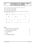
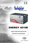
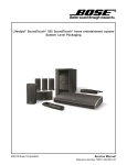
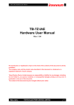
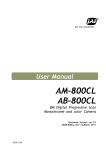
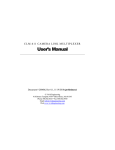
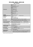
99
6.0
FRAME 6 ULTRADRIVE ELITE SERVICE
This section covers 400V models from UE-305 to UE-480 and 500V models from UE-305D to UE-540D.
MANUFACTURED BY
: UE-660
: 000000
380-440 VAC -20/+10% 3~ 48-62Hz
660 Amps
MODEL
SERIAL No.
VOLTAGE
CURRENT
PO BOX 741, NAPIER
NEW ZEALAND
PDL ELECTRONICS LTD
AC MOTOR SPEED CONTROLLER
The 400V and 500V models are essentially identical for disassembly and reassembly purposes. When specific
differences exist between the 400V and 500V models these are noted.
4508299A
CONTENTS
6.1
PARTS LISTS AND BLOCK DIAGRAMS
100
6.2
SERVICE
104
Elite Series Service Manual
4201-230 Rev B6
100
Frame 6
6.1
PARTS LISTS AND BLOCK DIAGRAMS
6.1.1
FRAME 6 400V ULTRADRIVE ELITE PARTS LIST
400 VOLT ULTRADRIVE ELITE PARTS LIST
FRAME 6
Frame Size
Model
UE-305
UE-340
Spares Guide
UE-420
UE-480
*Level 1 **Level 2
Display Unit
E480-620S
Control Board
E000-610S
1
1
Power Tray
E660-611S
1
1
SCR Board
6 x E660-615S
SCR Loom
2721-091
AC Power to Power Tray Loom
2721-124
4
Rectifier Block
6 x 1421-027
4
Rectifier Thermstrate
6 x 1781-103
4
24 x 1757-136
IGBT Block
24 x 1757-135
IGBT Thermstrate
24 x 1781-104
Gate Drive Board
3 x E480-612S
8
8
2
DC Bus Capacitors
24 x 1352-453
36 x 1352-453
Capacitor Sealing Rings
24 x 3907-004
36 x 3907-004
External Fans
4 x 2941-011
1
1
Main Internal Fans
2 x2941-006
1
1
2941-014
1
1
Power Tray Fan
6 x 3302-615
DC Bus Fuse
6 x 3302-616
6
Input Fuses
6 x 3302-615
6
6
SCR Board Fuse
6 x 2401-025
6
6
DC Power Supply Board Fuses
2 x 2404-063
2
2
E660-621S (Includes Fuses)
Power Supply Board
Thermal Sensor Boards
Thermal Sensor Looms
12 x E660-619S
4
Loom To Power Board 1 x 2726-105
1
Short Linking Loom 4 x 2721-114
3
Long Linking Loom 2 x 2726-103
1
2721-094
DC Power to Power tray Loom
DCCT
3 x 2521-073
3 x 2521-088
6 x 0371-609
Bus Sharing PCB
Fibre Optic Loom UH, UL & VL
3 x 2727-018 (715mm)
Fibre Optic Loom UL & WL
2 x 2727-016 (370mm)
Fibre Optic Loom WL
1 x 2727-017 (620mm)
* Level 1: Minimum spares stock
**Level 2: Typical spares stock
4508277A
Figure 6.1 :
Elite Series Service Manual
Frame 6 400V Parts List
4201-230 Rev B6
Elite Series Service Manual
Figure 6.2 :
L3
L2
L1
INPUT
FUSES
P1
P2
CHOKES
T1
RECTIFIER
T4
T1
T4
T2
F1
10A
P1
SCR BOARD
T3
SCR BOARD
P2
T2
F1
10A
RED
T3
YELLOW
GND
BLUE
BLUE
BROWN
BLACK
4 x 400V 3
PHASE FAN
P1
F1
10A
P2
T4
RECTIFIER
T1
T1
T4
T2
T3
T2
P2
SCR BOARD
F1
10A
P1
SCR BOARD
T3
6 x RECTIFIER
THERMAL SENSOR
BOARD
6 x INVERTER
THERMAL SENSOR
BOARD
LINK
P1 P3 P2
P1 P3 P2
END LINK LINK
F1
10A
P1
P2
T2
T4
F1
10A
P1
P2
T2
T1
+VE
10A
F1
-VE
10A
F2
-ve DC BUS
BUS
SHARING
BOARD
BUS
SHARING
BOARD
POWER SUPPLY BOARD
T4
SCR BOARD
T3
RECTIFIER
T1
SCR BOARD
T3
TERMINAL
10 to 12
CONTROL
BOARD
DRIVE SELECT
BOARD
POWER TRAY
BUS
SHARING
BOARD
DC BUS CAPACITORS
P204
LED301 - IC301
UH
P102
LED302 - IC302
UL
P103
LED303 - IC303
P104
VH
LED304 - IC304
VL
P105
THESE CAPACITORS 480A ONLY
P301
P302
P302
P205
U P301
V P302
W P303
LED305 - IC305
WH
P106
LED306 - IC306
WL
P107
12 x THERMAL SENSOR BOARDS
P305
P100
2 PLUGS SAME NUMBER
P101
P304
BUS
SHARING
BOARD
DC BUS CAPACITORS
P204
POWER TRAY FAN
INTERNAL
24VDC FAN
INTERNAL
24VDC FAN
P300
BUS
SHARING
BOARD
BUS
SHARING
BOARD
2 FIBRE OPTIC CABLES
3 CABLES
DC BUS CAPACITORS
LOOMED TOGETHER
BUS
SHARING
BOARD
BUS
SHARING
BOARD
4x PARALLEL IGBT’s
2x
DC
FUSE
VL
GATEDRIVE BOARD
UH
LED100 - IC102
P100
LED100 and IC102
P200
4x PARALLEL IGBT’s
2x
DC
FUSE
VL
GATEDRIVE BOARD
VH
LED100 - IC102
P100
LED100 and IC102
P200
400 VOLT FRAME 6 UE-305 TO UE-480 BLOCK DIAGRAM
4508-264A
4x PARALLEL IGBT’s
DCCT W
DCCT V
DCCT U
2x
DC
FUSE
WL
GATEDRIVE BOARD
WH
LED100 - IC102
P100
LED100 and IC102
P200
PE
-VE DC
BUS
W
V
U
+VE DC
BUS
6.1.2
Green/Yel
DISPLAY UNIT
Frame 6
101
FRAME 6 400V ULTRADRIVE ELITE BLOCK DIAGRAM
Frame 6 400V Block Diagram
4201-230 Rev B6
102
Frame 6
6.1.3
FRAME 6 500V ULTRADRIVE ELITE PARTS LIST
500 VOLT ULTRADRIVE ELITE PARTS LIST
FRAME 6
Frame Size
Model
UE-305D
UE-370D
Spares Guide
UE-440D
UE-540D *Level 1 **Level 2
Display Unit
E480-620S
Control Board
E000-610S
Power Tray
E661-611S
1
1
SCR Board
6 x E661-615S
2
4
SCR Loom
2721-088
AC Power to Power Tray Loom
2721-124
1
Rectifier Block
6 x 1421-040
2
4
Rectifier Thermstrate
6 x 1781-103
2
4
4
8
24 x 1757-136
IGBT Block
24 x 1757-135
IGBT Thermstrate
24 x 1781-104
4
8
Gate Drive Board
3 x E481-612
1
2
DC Bus Capacitors
24 x 1352-552
36 x 1352-552
Capacitor Sealing Rings
24 x 3907-004
36 x 3907-004
External Fans
5 x 2941-024
5 x 2941-022
1
2 x 2941-012
Main Internal Fans
1
2941-014
Power Tray Fan
6 x 3302-615
DC Bus Fuse
1
6 x 3302-500
6
Input Fuses
9 x 3302-615
6
6
SCR Board Fuse
6 x 2401-025
6
6
Power Supply Board Fuses
2 x 2404-063
2
2
E660-621S (Includes Fuses)
Power Supply Board
12 x E000-619S
4
6 x 2721-101
Loom To Power Board 1 x 2726-105
1
Short Linking Loom 4 x 2721-114
3
Long Linking Loom 2 x 2726-103
1
Thermal Sensor Boards
Microtherm Including Loom
Thermal Sensor Looms
2721-094
DC Power to Power tray Loom
DCCT
3 x 2521-073
3 x 2521-088
3 x 2521-072
6 x 0371-609
Bus Sharing PCB
Fibre Optic Loom UH, UL & VL
3 x 2727-018 (715mm)
Fibre Optic Loom UL & WL
2 x 2727-016 (370mm)
Fibre Optic Loom WL
1 x 2727-017 (620mm)
External Fan P/S Transformer
2571-067
1
External Fan P/S Board
E000-648
1
* Level 1: Minimum spares stock
**Level 2: Typical spares stock
4508-278A
Figure 6.3:
Elite Series Service Manual
Frame 6 500V Parts List
4201-230 Rev B6
Figure 6.4:
Elite Series Service Manual
L3
L2
L1
INPUT
FUSES
T3
P1
P2
T3
P1
P2
T3
F1
10A
P1
P2
EXTERNAL 24VDC FANS
CHOKES
T1
RECTIFIER
T4
T1
T4
RECTIFIER
T1
T4
T2
T4
SCR BOARD
T1
T2
F1
10A
SCR BOARD
F1
10A
T4
F1
10A
P1
P2
T2
T1
+VE
10A
F1
-VE
10A
F2
-ve DC BUS
BUS
SHARING
BOARD
BUS
SHARING
BOARD
INTERNAL
24VDC FAN
POWER TRAY
P301
P302
P302
P205
LED301 - IC301
UH
P102
LED302 - IC302
UL
P103
LED303 - IC303
P104
VH
LED304 - IC304
VL
P105
DC BUS CAPACITORS
THESE CAPACITORS 440Dand 540D ONLY
BUS
SHARING
BOARD
U P301
V P302
W P303
LED305 - IC305
WH
P106
LED306 - IC306
WL
P107
P204
12 x SENSOR BOARDS
P305
P100
2 PLUGS SAME NUMBER
P101
P304
P300
BUS
SHARING
BOARD
DC BUS CAPACITORS
P204
POWER TRAY FAN
INTERNAL
24VDC FAN
DRIVE SELECT
BOARD
POWER SUPPLY BOARD
T4
SCR BOARD
T3
RECTIFIER
T1
T2
P2
T2
F1
10A
P1
T2
T3
SCR BOARD
P2
6 x RECTIFIER
SCR BOARD
F1
10A
P1
THERMAL SENSOR
BOARD
6 x INVERTER
P1 P3 P2
LINK
THERMAL SENSOR
BOARD
P1 P3 P2
END LINK
SCR BOARD
T3
BLUE
6 x INVERTER MICROTHERMS
TERMINAL
10 to 12
CONTROL
BOARD
BUS
SHARING
BOARD
BUS
SHARING
BOARD
2 FIBRE OPTIC CABLES
3 CABLES
DC BUS CAPACITORS
LOOMED TOGETHER
BUS
SHARING
BOARD
BUS
SHARING
BOARD
4x PARALLEL IGBT’s
2x
DC
FUSE
VL
GATEDRIVE BOARD
UH
LED100 - IC102
P100
LED100 and IC102
P200
4x PARALLEL IGBT’s
2x
DC
FUSE
VL
GATEDRIVE BOARD
VH
LED100 - IC102
P100
LED100 and IC102
P200
500 VOLT FRAME 6 UE-305D TO UE-540D BLOCK DIAGRAM
4508-267A
4x PARALLEL IGBT’s
DCCT W
DCCT V
DCCT U
2x
DC
FUSE
WL
GATEDRIVE BOARD
WH
LED100 - IC102
P100
LED100 and IC102
P200
PE
-VE DC
BUS
W
V
U
+VE DC
BUS
6.1.4
WHITE
EXTERNAL
24VDC FAN
SUPPLY
DISPLAY UNIT
Frame 6
103
FRAME 6 500V ULTRADRIVE ELITE BLOCK DIAGRAM
Frame 6 500V Block Diagram
4201-230 Rev B6
104
Frame 6
6.2
SERVICE
6.2.1
SERVICING THE CONTROL BOARD
1)
Control
Board
Plugs
Ensure the Elite is safe to work, see section 4.2
before proceeding.
2)
Number the three way controls to enable easy
replacement then unplug them and remove the
control cable clamps if used.
3)
Referring to figure 6.5 access to the wiring looms
on the lower left hand side by removing screws A (3
off CW M4x10) retaining this plate.
4)
Unplug the 7 wiring looms under the plate.
5)
Remove the remaining cover plates in one
assembly by removing screws B, 3 off M4x10.
Slide the cover plate assembly down to clear the
fibre-optic connections before lifting it clear.
6)
Referring to Figure 6.6, the Control board is held
by the Phillips screws C, 3 off M4x10 screws.
Remove these and lift the control board vertically
off the connecting pins.
Note: lift beside the plugs and keep the board level
to avoid bending the connecting pins.
7)
500V models have a drive select board between
the Control board and the Power tray, leave this in
place.
8)
The replacement Control board will be in biscuit
format i.e. it will have to be trimmed to the same
size as the existing board size as per figure 6.8.
This is done with a fine pair of side cutters.
9)
Place the Control board on the connecting pins
C
C
FAN USED ON
FRAMES 6 & 7
ONLY
CONTROL
BOARD
C
4508-258A
Figure 6.6:
Board
Frame 5 to 7 Power Tray and Control
Figure 6.7:
Frame 5 to 7 Power Tray Exploded View
Figure 6.8:
Frame 4 to 7 Control Board Biscuit
10) Gently push the 6 pin connector down slightly and
repeat the process with the 40 pin connector.
When this is completed, check through the slots to
ensure no connecting pins are showing or
damaged then push the Control board completely
home. Replace the 3 off M4x10 Phillips screws as
per figure 6.6.
11) Replace the remaining components of the Elite in the
opposite order as detailed in removing the Control
board.
INTERNAL
FAN WIRES
PE
PE
FIBRE OPTIC
COVER PANEL
M4x10 CW
SCREW
B
B
B
A
DC FUSE
PCB LOOM
B
B
POWER TO POWER
PCB LOOM
SCR PCB LOOM
U V W
A
THERMAL SENSE
PCB LOOM
A
B
3 OF CT LOOM
CONTROL BOARD
EARTH
3 WAY PLUG
CONTROL CABLE
CLAMPS
Figure 6.5:
Frame 5 to 7 Power Tray
Elite Series Service Manual
4201-230 Rev B6
105
Frame 6
6.2.2
SERVICING THE POWER TRAY
The Power Electronics board is replaced as an entire
assembly, that is, inclusive of the mounting tray. This
assembly is referred to as the Power tray .
DRIVE
SELECT
1) See section 6.2.1 on removing Control board.
2) When the Control board has been removed, put it onto
the new Power tray. For 500V models, move the Drive
Select board to the new Power Tray, see figure 6.10.
For 400V models, this can be done after the Control
board is in place, see figure 6.9.
Referring to figure 6.11.
3) Remove any customising items that may have been
fitted in the space provided on the mounting tray.
4) Remove the lexan shield over the fibre optic looms.
5) At the top of the Power tray remove the wired
connectors UL to WH (do not pull on the cables) then
remove the fibre optic plugs UL to WH.
6) Unplug the internal fan plug from the top left of the
Power tray.
7) Loosen the two off Power Tray retaining screws and lift
the Power tray clear.
4508-295A
Figure 6.9:
400V Power tray
8) Place the new Power tray in the Elite and replace the
wiring looms etc. in the opposite order that they were
removed. Take care that the connectors are replaced
without crossing phases, and without inadvertently off
setting pins. The fibre optic looms and circuit board
are marked to ensure the connections are made
correctly. Particular care must be taken with the fibre
optic looms to avoid a bending radius of less than
35mm.
DRIVE
SELECT
9) Replace the lexan shield over the fibre optic looms.
Before mains powering the Elite, it is recommended to
Soft Power the Elite to test the new parts are functioning
correctly without risk of damage should something else
be faulty or an error made during reassembly. See
section 4.6.
4508-294A
Figure 6.10:
Elite Series Service Manual
500V Power tray
4201-230 Rev B6
106
Frame 6
DOOR PILLAR
M5x16 CW SCREWS
INTERNAL FAN
2 OF
POWER TRAY SUPPORT
RAIL
2001311C
A
F
IC1
A
P1
2001311C
F
IC1
A
P1
E
2001311C
F
IC1
A
P1
2001311C
E
P2
E
P2
PRODUCT No. E480-612
CIRCUIT No. 0410-254 Rev.
PDL ELECTRONICS LTD
PE
F
IC1
P1
E
P2
PRODUCT No. E480-612
CIRCUIT No. 0410-254 Rev.
PDL ELECTRONICS LTD
P2
POWER TRAY
RETAINING SCREWS
PE
M5x16 CW SCREWS
LEXAN (CLEAR)
INTERNAL SHIELD
LEXAN (CLEAR)
C1
M4x16 CW SCREWS
C3
CAUTION
CAUTION
STORED
CHARGE
STORED
CHARGE
INTERNAL SHIELD
M4x16 CW SCREWS
U PHASE
OUTPUT SHEETBUS
W PHASE
OUTPUT SHEETBUS
W
V
U
SENSOR
POWER TRAY
ASSEMBLY
A
P2
2001311C
P1
P2
2001311C
P1
F
IC1
F
IC1
E
E
HVDC
U
OUTPUT
W
V
: UE-660
: 000000
380-440 VAC -20/+10% 3~ 48-62Hz
660 Amps
MODEL
SERIAL No.
VOLTAGE
CURRENT
INPUT
L1
L3
L2
HIGH LEAKAGE CURRENT
EARTH CONNECTION ESSENTIAL
BEFORE CONNECTING SUPPLY
WARNING
4101-497 Rev. A
PO BOX 741, NAPIER
NEW ZEALAND
MANUFACTURED BY
AC MOTOR SPEED CONTROLLER
+ HVDC
PDL ELECTRONICS LTD
INPUT FUSES
2 PER PHASE
4101-459 Rev A
The heatsink cooling fans on this unit are mains phase sequence sensitive.
Ensure that the cooling air is blowing out from the top of the unit.
ACHTUNG
..
..
Das Gerat muB, wegen der Lufter, mit richtiger Phasenfolge am Netz
..
angeschlossen werden. Die Kuhlluft muB oben austreten.
4508303A
Figure 6.11:
Elite Series Service Manual
Frame 6 Power Tray Removal
4201-230 Rev B6
107
Frame 6
6.2.3
SERVICING THE OUTPUT SHEET BUS
Frame 6 construction allows one phase to be disassembled without affecting the other two. This section and the
following describe how to disassemble U Phase. The other two phases are similar in construction.
Ensure you have adequate small containers to place the Bus Sharing Board, DC Supply Board, positive Sheet Bus and
negative Sheet Bus fixings in their own container. This will help to speed up reassembly.
To remove the U Phase output Sheet Bus remove:
1)
The door pillar which is held by 8 off M5x16 CW screws. See figure 6.12.
2)
The Lexan shield 2 off M5x 6 CW screws. See figure 6.12.
3)
Screws A and B.
4)
Bolts C and D.
Thread the fibre optic loom through the output Sheet Bus.
Slide the output busbar towards the bottom of the Elite (do not slide it completely through the grommet). If it is sticking
use some soapy water.
(ROUTE THROUGH GROMMET IN
OUTPUT SHEET BUS)
2001311C
LOOM: F/OPTIC 620mm
LOOM: F/OPTIC 715mm
(ROUTE THROUGH GROMMET IN
OUTPUT SHEET BUS)
(ROUTE THROUGH GROMMET IN
OUTPUT SHEET BUS)
LOOM: F/OPTIC 715mm
A
LOOM: F/OPTIC 370mm
LOOM: F/OPTIC 370mm
LOOM: F/OPTIC 715mm
F
IC1
A
P1
2001311C
F
IC1
A
P1
E
2001311C
F
IC1
A
P1
E
P2
2001311C
F
IC1
A
P1
E
P2
CIRCUIT No. 0410-254 Rev.
PDL ELECTRONICS LTD
A
A
2001311C
F
IC1
P1
E
E
P2
PRODUCT No. E480-612
CIRCUIT No. 0410-254 Rev.
PDL ELECTRONICS LTD
A
F
IC1
P1
P2
PRODUCT No. E480-612
CIRCUIT No. 0410-254 Rev.
PDL ELECTRONICS LTD
A
2001311C
E
P2
PRODUCT No. E480-612
A = M6 x 16 CW SCREW
B = M6 x 16 CW SCREWS
C = M8 x 40 BOLT, FLAT AND
SCHNORR WASHER
C = M6 x 25 BOLT, 2 X FLAT AND
1 X SCHNORR WASHER
P2
A
C1
C1
C3
C1
C3
C3
CAUTION
CAUTION
CAUTION
STORED
CHARGE
STORED
CHARGE
STORED
CHARGE
V OUTPUT SHEET BUS
U OUTPUT SHEET BUS
W OUTPUT SHEET BUS
C
B
B
B
B
B
B
C
C
2001311C
P1
P2
A
2001311C
P1
P2
A
2001311C
P1
P2
A
C
F
IC1
F
IC1
F
IC1
E
E
E
D
4508-304A
Figure 6.12:
Elite Series Service Manual
Frame 6 Output Sheet Bus Removal
4201-230 Rev B6
108
6.2.4
Frame 6
SERVICING THE POSITIVE AND NEGATIVE SHEET BUS
Bus Sharing and Power Supply Board Removal
Refer to figure 6.13 and 6.14.
1)
Remove the Bus Sharing boards and Bus Sharing cable. These two assemblies are secured with 6 off M5x30
CW screws and use 6 off 16mm long brass spacers. It is best to remove them as a full assembly keeping the
screws and spacers together, this makes for easier reassembly.
2)
Remove the Power Supply board, this is secured by 4 off M5x30 CW screws and has four brass spacers. The
outer two spacers are 16mm long and the inner pair are 16.8 mm long. It is best to remove them as a one
assembly keeping the screws and spacers together, this makes for easier reassembly.
3)
It is not necessary to unbolt the DC Bus fuses as the positive Sheet Bus can be removed as one piece.
A
2001311C
F
IC1
A
P1
2001311C
F
IC1
A
P1
2001311C
F
IC1
A
P1
E
E
P2
2001311C
F
IC1
A
P1
E
P2
CIRCUIT No. 0410-254 Rev.
PDL ELECTRONICS LTD
C1
A
R1
A
R1
A
A
SPACERS
16 LG
B
F
IC1
P1
E
P2
C3
R1
A
2001311C
C1
C3
R1
A
P2
PRODUCT No. E480-612
CIRCUIT No. 0410-254 Rev.
PDL ELECTRONICS LTD
C3
F
IC1
E
P2
PRODUCT No. E480-612
CIRCUIT No. 0410-254 Rev.
PDL ELECTRONICS LTD
C1
2001311C
P1
E
P2
PRODUCT No. E480-612
B
B
A
A
R1
A
A
R1
A
A
A
B
A
P2
2001311C
P1
2001311C
P1
P2
A
2001311C
P1
P2
A
F
IC1
F
IC1
F
IC1
E
E
E
SPACER 16.0 LG
A = M5 x 30 CW SCREW
2 OUTER POSITIONS
B = M5 x 30 CW SCREW
C
C = M6 x 25 BOLT, NUT,SCHNORR
2 MIDDLE POSITIONS
4508-306A
OUTPUT BUSBAR REMOVED FROM
ELECTRONICS CABINET
Figure 6.13:
Elite Series Service Manual
Frame 5 Positive and Negative Sheet Bus
4201-230 Rev B6
109
Frame 6
Positive and Negative Sheet Bus Removal
Note: This drawing has been labelled to assist more with reassembly than disassembly.
1)
Remove the DC output busbar by removing:
See figure 6.14. and remove bolts J, these bolts connect the positive output busbar to the positive Sheet Bus.
See figure 6.13. and remove bolts C where the busbar exits the electronics cabinet.
Slide the busbar into the termination area, do not slide it completely through the grommet (use soapy water if it is
sticking)
Refer to figure 6.14.
2)
Remove the positive Sheet Bus starting from screws F to J and the positive Sheet Bus joining bolts.
3)
Remove the negative Sheet Bus Starting from screws B to E and the negative Sheet Bus joining bolts.
4)
If you are not going to change the capacitors do not remove the cap centre Sheet Bus (screws A)
W
I
POSITIVE SHEET BUS
I
F = M3 x 10 CW SCREWS
G = M6 x 16 CW SCREWS
H = M5 x 12 CW SCREWS
I = M6 x 16 CW SCREWS
J = M8 x 20 BOLT, WASHERS
& NUT
I
I
V
POSITIVE SHEETBUS
JOINING BOLTS
M8 x 20, WASHER & NUT
I
I
I
J
H
I
U
J
H
I
H
I
H
I
G
H
I
H
H
H
G
H
BUS SHARING
G
F
H
H
H
G
H
POWER SUPPLY
BOARD
H
G
G
F
F
SHEETBUS SHIELDS
CLEAR LEXAN
F
F
F
THIS ROW 420A
TO 540A ONLY
NEGATIVE SHEET BUS
D
D
C
D
C
D
C
D
C
D
E
NEGATIVE SHEETBUS
JOINING BOLTS
M8 x 20, WASHER & NUT
D
B
C
C
D
D
C
B
C
E
CAP CENTER SHIELDS
CLEAR LEXAN
B
D
C
D
C
E
C
D
B = M8 x 16 BOLT & WASHERS
C = M5 x 12 CW SCREWS
D = M6 x 16 CW SCREWS
E = M8 x 20 BOLT, WASHERS
& NUT
B
C
C
B
C
B
A
A
A
A
A
A
A
A
Figure 6.14:
Elite Series Service Manual
A
A
A = M5 x 12 CW SCREWS
A A
A
A A
A
A A
A A
A
THIS ROW 420A
TO 540A ONLY
CAP CENTER SHEETBUS
A
THIS ROW 420A
TO 540A ONLY
A
A A
4508-308 Rev. A
A
A A
Frame 5 Positive and Negative Sheet Bus 3D View
4201-230 Rev B6
110
6.2.5
Frame 6
SERVICING THE IGBT GATEDRIVE BOARD
Ensure you have a means of shorting out the gate and emitter of the IGBTs before you remove the Gatedrive board.
Refer to the upper section of figure 6.14.
1)
Remove screws (A) 2 off, (B) 8 off and (C) 1 off on the phase you require access to and lift off the Gatedrive
board.
2)
Short out the gate and emitter on the IGBTs.
6.2.6
SERVICING THE SCR BOARD
Refer to the lower section of figure 6.14.
1)
To get access to the SCR Board, first remove the DCCT and DCCT mounting bracket as one assembly. The
bracket is held by 2 off M4x12 CW screws. Lay the DCCT and bracket carefully to one side.
2)
Remove the choke rectifier busbar fixings D, E and F then slide the Bar through the grommet just enough to allow
access to the SCR Board. It is best to avoid pulling out the Bus Bars if possible, as they can be difficult to put
back in (use soapy water if necessary).
3)
Remove the screws G and H unplug P1 (Note: P1 and P2 are common connections to the SCR gate).
4)
The SCR Board is now only held to the SCR by male spade terminals. The SCR Board can now be lifted vertically
off the SCR/diode block.
EARTH TAB
A
2001311C
F
IC1
A
P1
2001311C
C
F
IC1
P1
E
A
E
P2
PRODUCT No. E480-612
PRODUCT No. E480-612
CIRCUIT No. 0410-254 Rev.
CIRCUIT No. 0410-254 Rev.
PDL ELECTRONICS LTD
PDL ELECTRONICS LTD
B
B
B
B
B
B
C
F
IC1
P1
P2
B
2001311C
E
P2
B
GATEDRIVE BOARD
A = M6 x 12 CW SCREW
B = M4 x 10 CW SCREW
C = M4 x 10 CW SCREW
A
A
B
A
B
A
B
B
B
B
+
+
+
+
+
+
+
+
+
+
B
B
CHOKE RECTIFIER BUSBAR
D = M3 x 10 CW SCREW
E = M6 x 16 CW SCREW
+
+
-
P2
F
D
E E
E E
G
E
E
E
G
D
F
IC1
F
IC1
F
IC1
F
+
2001311C
P1
P2
F
A
+
F = M8 x 16 BOLT FLAT AND
SCHNORR WASHER
+
2001311C
P1
P2
2001311C
P1
F
+
A
-
A
+
+
SCR BOARD
F = M3 x 10 CW SCREW (T3)
G = M3 x 10 CW SCREW ( EARTH TAB)
THERMAL SENSE
PCB LOOM
4508309A
Figure 6.14:
Elite Series Service Manual
Frame 6 Snubber and SCR Board
4201-230 Rev B6
111
Frame 6
6.2.7
SERVICING THE IGBT
Refer to the upper section of figure 6.13.
Each IGBT is held by 4 off M6x16 CW screws, a thermstrate is used between the IGBT and heatsink to ensure good
thermal contact. Remove the old IGBTs and clean the heatsink surface.
1)
Do not remove the gate emitter shorting link on the new IGBTs.
2)
Use a new thermstrate, avoid touching the surface of it , do not use the paper packer.
3)
Replace the 4 off M6x16 CW screws (do not tighten yet) and push the IGBT block towards the base of the Elite,
then tighten the screws. This will align the replacement blocks in the same manner as the remaining half phases.
4)
Remove the gate emitter shorting ribbon from the IGBTs and replace the Gatedrive board.
6.2.8
SCR/DIODE BLOCK SERVICE
Refer to the lower section of figure 6.12.
Each SCR/diode block is held by 4 off M5x16 CW screws, and a thermstrate is used between the SCR/diode block and
heatsink to ensure a good thermal contact. Remove the old SCR/diode block and clean the heatsink surface.
1)
Use a new thermstrate, avoid touching the surface of it, do not use the paper packer.
2)
Replace the 4 off M5x16 CW screws (do not tighten yet) and push the SCR/diode block towards the bottom of the
Elite, then tighten the screws. This will align the replacement blocks in the same manner as the remaining half
phases.
500V MICROTHERMS
The 500V models have three microtherms connected to and located above the top set of Thermal Sense boards.
M3x10 CW SCREW
2001311C
F
IC1
A
P1
2001311C
F
IC1
P1
E
E
P2
2001311C
F
IC1
2001311C
A
P1
A
F
IC1
P1
P1
E
E
P2
P2
E
P2
E
E
B
E
B
E
C
C
A
E
P2
E
F
IC1
P1
B
2001311C
E
B
E
E
B
B
E
C
A
P2
E
A
E
C
B
E
C
E
C
C
M6x16 CW SCREWS
C
C
C
C
C
C
C
E
E
E
E
E
E
E
B
B
E
B
E
B
E
B
E
B
B
E
IGBT & THERMSTRATE
NOTE ORIENTATION
IGBTs TO BE MATCHED
E
E
M5x12 CW SCREWS
+
+
+
+
+
+
+
CAPACITORS
NOTE POLARITY
+
+
+
+
+
+
+
CLAMPING PLATE
+
+
+
+
+
THIS ROW 440/540 and
420/480 AMP ONLY
+
-
IN
+
-
+
P1
P2
2001311C
P1
P2
2001311C
P1
P2
2001311C
P1
P2
2001311C
F
IC1
F
IC1
F
IC1
F
IC1
E
E
E
E
RECTIFIER & THERMSTRATE
IN
A
IN
A
-
A
+
A
IN
FIT M3 x 6 CW SCREWS
TO PLUG THESE HOLES
LOCTITE SCREW NEAR H/S EDGE
4508-310A
M5x16 CW SCREWS
(4 OF PER RECTIFIER)
THERMAL SENSE PCB
Figure 6.15:
Elite Series Service Manual
Frame 6 IGBT, Capacitors and SCR Level
4201-230 Rev B6
112
6.2.9
Frame 6
SERVICING THE CAPACITOR
The capacitors are mounted through the heatsink with the bulk of the capacitor in the main cooling airflow at the back
of the machine. Sealing rings are used to prevent air leakage through to the inside of the machine.
1)
To remove the capacitors, undo 15 off M5 x 12 Phillips screws. See figure 6.15.
Replacing the Capacitors
1)
The capacitors should be installed using a jig, PDL part number 5101-190, this ensures the height and rotational
position are exact.
The sealing rings must be fitted to the capacitors at 23.5mm below the top of the terminal post. Place the
capacitors in the heatsink and loosely screw down the clamping plate. Fit the jig to the capacitors then tighten the
clamping plate screws. If a jig is not available precise fitting of the individual capacitors is required. Refer to
figure 6.16. Fit the capacitor sealing rings exactly as shown, this should help to align the capacitor terminal post
at 29.5 mm above the heatsink, when the clamping plate is secured. The rotational alignment of the post is also
critical to prevent cross threading of the screws into the capacitor terminal post when the Sheet Bus is attached.
Slight adjustments may need to be made as the clamping plate is clamped down.
Sealing Ring Before
Inserting Capacitor
Into Heatsink
23.5mm
Capacitor Replacement
Complete
Clamping
Plate
29.5mm
Heatsink
Sealing
Ring
4508-302A
Figure 6.16:
Elite Series Service Manual
Capacitor Replacement
4201-230 Rev B6
113
Frame 6
6.2.10
500V MODELS EXTERNAL FAN POWER SUPPLY
The 500V models have a linear AC to 24Vdc power supply for the external fans. This is located directly above the
internal cooling fan and is accessed by removing the gold coloured panel above the electronics cabinet. The panel is
held by 6 off M5 x 10 CW screws.
An exploded assembly view is shown in figures 6.17 and 6.18.
Elite Series Service Manual
5
4
Frame 5 to 7 500V External Fan Supply Connections
3
Figure 6.18:
2
Frame 5 to 7 500V External Fan Supply
1
Figure 6.17:
4201-230 Rev B6
114
Notes
Elite Series Service Manual
4201-230 Rev B6