1
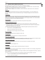
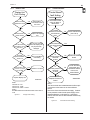
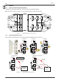
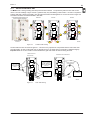
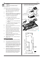
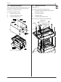
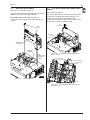
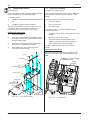
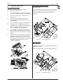
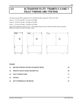
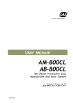
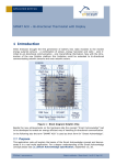
25 2.0 MICRODRIVE ELITE SERIES FRAME 3 This section covers 400V models ME-31 to ME-46 and 500V models ME-30D to ME-41D The 400V and 500V models are essentially identical for assembly purposes. When specific differences exist between the 400V and 500V models, these are noted. ON START RUN OK STOP RESET 4508-290A CONTENTS 2.1 BEFORE STARTING TESTING OR SERVICE WORK 26 2.2 PRINTED CIRCUIT BOARD DESCRIPTIONS 27 2.3 FAULT FINDING GUIDE 28 2.4 TESTING 32 2.5 SOFT POWERING AFTER REPAIR 35 2.6 PARTS LIST AND BLOCK DIAGRAM 36 2.7 SERVICE 38 Elite Series Service Manual 4201-230 Rev B3 26 2.1 Frame 3 BEFORE STARTING TESTING OR SERVICE WORK Site Preparation This size of Elite is best serviced on a bench. We recommend a bench with an earthed antistatic mat for working on and an earthed wrist strap. You will need flat surfaces for placing parts on and containers for small items like screws and bolts. Tool Requirements 1 x No. 2 Phillips screwdriver 1 x No. 3 Phillips screwdriver 1 x Flat blade 3.5 mm screwdriver for terminals 1 x Flat blade 5.5 mm screwdriver 1 x No. 3 Square drive screwdriver 1 x 5.5mm nutdriver 1 x 7mm nutdriver 1 x 10mm nutdriver 1 x Category 3 multimeter with ranges to 1000V AC and DC maximum 1 x PDL Soft Power Supply 1 x Single Phase variac 1 x Isolating transformer (Optional) 1 x 24Vdc volt power supply. (a current limit supply is preferred but a simple plug pack or batteries can be used with a lamp in series to limit the current flow) 4 off 230Vac 100W lamps and lamp holders Safety & Testing Before Starting Repairs 1) Isolate and lock out the mains supply to the Elite and any low voltage supply that may be in parallel with the control power supply. 2) Allow approximately 5 minutes for the DC Bus capacitors to discharge. 3) Remove the right hand cover by undoing 6 off Phillps head screws. Note: these screws stay in the cover. Check the DC Bus live indicator on the bottom right of the Control board, the red LED should not be glowing. 4) Remove 6 off Phillps head screws to remove the left cover. Then remove the lexan terminal cover. 5) Test between input terminals L1, L2, L3 and L1, L2, L3 to earth to ensure the supply has been disconnected. 6) Finally, test between the HVDC terminals +VE and -VE to ensure the DC Bus has fully discharged. Elite Series Service Manual 4201-230 Rev B3 27 Frame 3 2.2 PRINTED CIRCUIT BOARD DESCRIPTIONS IP54 models are built in two enclosures, with 4 bushes connecting the enclosures. The right enclosure contains: Display unit, IGBTs, DC Bus capacitors, Gatedrive board, Control board, internal cooling fans, DC current transformer interface & control terminations. The left enclosure contains: Power terminations, common mode choke, rectifier and DC current transformers (DCCTs). Display Unit The Display unit has three buttons and a 2 by 16 character liquid crystal display. It is the user interface for all parameter settings and is common to the Elite Series range. The Display unit plugs into the Control board user terminals. Control Board The Control board is common to the Elite Series range and accepts all external control inputs and generates output signals. These include digital, analogue and fibre optic signals. A Modbus RTU serial communications port is also included on the Control board. A Shaft Encoder interface and 5V power supply is standard. The Control board also has a bidirectional 24Vdc user power supply rated at 500mA. Gatedrive Board The Gatedrive board is a general purpose board and as such performs many functions. Gatedrive and Desaturation Circuits Six gatedrive circuits accept gatedrive signals from the Control board and turn on/off the respective IGBT. Monitoring the IGBTs for overload conditions and turns the relevant IGBTs off if this should occur and generates Desaturation (Desat) fault to the Control board. The main switch mode power supply provides various isolated DC supplies required by the Elite. These are: 4 off +16.5V, 0V, -13.5V for gatedrive circuitry. 28Vdc for the internal fans and the Control board. 24Vdc 500mA user power supply (via the Control board). Bus Live Indication One red light emitting diode (LED) to indicate the DC Bus is live. Circulating Fans IP54 models only have two internal fans for circulating air within the Elite. Thermal Sense (400V models) An NTC thermal sensor circuit is connected to the heatsink via a small tab. This circuit monitors the heatsink and will cause the Elite to trip on a thermal fault if the heatsink temperature exceeds 80°C (176°F). Thermal Sense (500V models) A separate Thermal Sense Board and 2 off 90°C (194°F) microtherms are included in these models. Capacitor Board This board has the DC Bus capacitors on it. Power Board The Power Board has snubber capacitors and IGBT blocks power connections. Rectifier Board The Rectifier Board has a switch mode power supply, soft charge circuit, snubber circuit, RFI filtering, voltage transient protection (500V only) and SCR gatedrive. There is no external control to this board, the soft charge is initiated on power being applied to the board (i.e. when the Elite is powered up). SCR switch mode power supply provides various isolated DC supplies required by the Elite. These are: +15V, 0V, for SCR Gatedrive circuitry and DC Bus discharge control. +5V, 0V for switch mode regulation. Elite Series Service Manual 4201-230 Rev B3 28 Frame 3 2.3 FAULT FINDING GUIDE 2.3.1 SUPPLY ISSUES Power supply problems can be misinterpreted as faults in the Elite, some are listed below: Fault 01 LOW Vdc The supply to the Elite is dropping below the switch mode power supply operating level and the Elite is shutting down. This is usually caused by a weak supply or faults in the supply system. Look for motors starting direct on line or other machines drawing high current. For further details see the fault list in section 8 of this manual. Fault 02 HIGH Vdc The supply to the Elite is surging too high. Rapid load changes in the supply system may be faster than automatic tap changing transformers can adjust to. For further details see the fault list in section 8 of this manual. Fault 04 SUPPLY FLT Supply fault (Fault 04) is an indication that the ripple on the DC Bus has exceeded 40Vac. The Elite will trip if this condition is reached and will display Fault 04 SUPPLY FLT. This can be caused by diode(s) in the rectifier going open circuit, see section 2.4, but is more likely to be caused by; The loss of an input phase which increases the ripple on the DC Bus. The Elite will run on two phases up to about half to two thirds of its current rating, at which point the DC Bus filter will not be capable of maintaining the ripple below 40Vac and the Elite will trip. The Display unit will stay live. The Elite can be reset and will run to about the same current before tripping again. Excessive mains distortion (harmonics) can also cause excessive ripple on the DC Bus. The cause of excessive supply distortion in an industrial situation may be; SCR controlled heating equipment, DC drives, current source inverters, and other high current non linear loads. This can also occur where backup generators are used and they have not been sized correctly relative to the total variable speed drive load (VSD). The total loading of VSDs on a backup generator should be about 60% and the remaining 40% made up of linear loads. 2.3.2 FUSE FAILURE Fuse failure is not a normal event, and it usually indicates a more serious fault. Therefore, the reason for fuse failure should be investigated. Supply Fuses Location: At point of supply to the Elite. Possible reason for failure: Supply surge, age or cyclic stress failure, wrong fuses, fault in supply cable to the Elite, rectifier, or inverter fault, motor or motor cable fault. Action: 1) See section 2.1 before starting. 2) Perform a visual inspection for mechanical damage, water entry, or any other possible damage to the system. 3) For new or modified installations check the wiring is correct as per the Technical Manual 4201-180. 4) Check fuses for correct rating. 5) Disconnect supply cables and test for phase to phase or phase to earth fault. 6) Mark and disconnect the output cables, test the cables and motor for phase to phase and phase to earth fault. 7) Test the Elite for rectifier, inverter or DC Bus faults as per section 2.4. 8) If no faults are found, the best option is to softpower the Elite as per section 2.5. If the fuses failed because of an external issue such as short term overload or cyclic stress, reconnect the Elite, replace the fuses and attempt to run the Elite. Control Board Fuse Location: on the Control board. This fuse is in series with the user 24Vdc 500mA power supply accessed via T36 and T37. The user power supply is short circuit protected and will close down if a short is present in the field control wiring or other device connected to T36 and T37. Elite Series Service Manual 4201-230 Rev B3 29 Frame 3 2.3.3 DISPLAY UNIT 2.3.4 Display Unit Fault Finding Is the screen appearance normal CONTROL BOARD Control Board fault finding Yes Put the Elite in commission mode see note 2 Check field control wiring for faults or disconnect it No Are there lines of pixles missing Yes Replace the Display Unit Is 28VDC present on the fan terminals see note 1 No Check external fans (see note 2) Yes No Are the screen terminations correct see note 1 Re-connect correctly No Note The Display Unit may be permantly damaged Has the Control Board had high voltage applied to it Yes No Yes Is 24VDC present between T10 & T12 No See Control Board fault finding Yes Is 24VDC present on terminals 20 & 21 No Replace the Control Board Yes Is the Display Unit mounted > 3 metres from the Elite Yes Reduce to 3 metres Is 24VDC present on terminals 37 & 36 No Check the field wiring again and replace the 500mA fuse on the Control Board No Yes Replace Display Unit 4508-249A Note 1 Terminal 10 - red Terminal 11 - white Terminal 12 - black + screen Note 2 See Elite Series technical manual 4201-180 screen Z to Z1 Figure 2.1: Display Fault Finding Replace the Control Board Note 1 The fan terminals are located between the fibre optic connections at the bottom of the Control Board. Note 2 Disconnect fan and recheck 28 volt supply. If 28Vdc is not present the switch mode power supply on the Gatedrive Board is not functioning. If the supply returns when the fans are disconnected the fans may be at fault. Figure 2.2: Elite Series Service Manual 4508-250B Control Board Fault Finding 4201-230 Rev B3 30 2.3.5 Frame 3 INPUT RECTIFIER The Rectifier is a half controlled bridge that combines DC conversion and the softcharge section of the Elite into one stage. The SCR(s) on Line 1 are phase controlled to limit the inrush current to the DC bus capacitors when the Elite is powered up. This is termed "Soft Charge". The phase control is continued until the capacitors are fully charged then all SCRs are turned on. Rectifier/softcharge failure can be indicated by input fuses blowing on power application or display of SUPPLY FAULT, especially on application of load. Soft Charge failure Failure of soft charge function: Some or all of the SCR's may not respond to a gate signal or the rectifier board may not be producing a gatedrive signal. This indicates a failure in the Rectifier board or SCR/Diode block. Diode or SCR Failure: If part of the rectifier stage has failed open circuit the Elite may not soft charge and no voltage will appear on the DC bus. Note: it is uncommon for semiconductors to fail open circuit. Some causes of rectifier failure Bus Capacitor Failure: Excess current drawn by a shorted capacitors may damage the rectifier. See section 2.3.7. Internal fault in Elite: Failure to a short circuit will cause the two input phase fuses to blow. Fault in supply cable, motor cable or motor. Input supply imbalance: If Line 1 (L1) is low with respect to yellow and blue, the Elite will soft charge the capacitors to 1.414 x the L1 RMS voltage level. When the soft charge is finished, the SCRs on L2 and L3 will be turned on fully applying a higher DC level to the DC bus than is currently there. This can generate sufficient inrush current to damage the input rectifier. Supply voltage excess: The Elite has VDR's to protect against voltage transients. These will not cope with a supply that is constantly above the maximum level the Elite was designed for. The VDRs will fail and the Elite may be damaged. 2.3.6 INVERTER The inverter consists of insulated gate bipolar transistors (IGBTs). Each IGBT block has two transistors, one for the upper and one for the lower half phase. Symptoms of Inverter failure Input fuses blowing on power application. DESAT fault 08 to 13 constantly on the same phase and polarity. Current limit fault 07 this is a hardware trip to indicate that 220% of rated current has been reached. For all of the above faults, test the IGBTs as per section 2.4.1. Check the motor and motor cables. If no faults are found, attempt to reset the Elite. If the fault is repetitive on the same phase and polarity, check the IGBTs again. If the fault is a DESAT fault and not always on the same phase, the problem is most likely in the Gatedrive board, output cables or motor. IGBT Replacement Batch matching of IGBTs is not required for Frame 3 but it is required with Frames 5 to 7. 2.3.7 DC BUS FILTER The DC Bus filter is comprised of electrolytic capacitors and chokes. The chokes are mounted in the DC Bus and are in series with the rectifier output. The filters function is to reduce the harmonic current drawn by the Elite and the ripple on the DC Bus, excess ripple >40Vac will be detected and displayed as a supply fault. To achieve the required voltage rating, two capacitors are connected in series. The capacitors are rated at 400V and 450V for the 400V and 500V models respectively. The capacitors are connected in parallel. Possible Causes of Failure The definition of capacitor failure is for the capacitance of the capacitor to fall outside manufacturers tolerance or suffer a catastrophic failure which is an open or short circuit. While this section is quite detailed the capacitors seldom cause any problems. 400V capacitors rating 680 MFD +/- 20% at 20°C and 120Hz. 500V capacitors rating 560 MFD +/- 20% at 20°C and 120Hz. Elite Series Service Manual 4201-230 Rev B3 31 Frame 3 Factors Affecting The Life of The DC Bus Capacitors Stress related issues: these are vibration, excessive ripple, excessive voltage and/or temperature. Over heating is the most likely cause of premature failure and can be brought about by reduction in cooling air flow to the drive. Check the heatsink for blockage and the fan operation. Check for excessive ambient temperature or excess ripple due to some of the capacitors going open circuit. Shelf life: the recommended storage period without use should not exceed 3 years. If there is concern regarding the time an Elite has been stored, a DC supply can be connected to the DC Bus terminals. Starting at about 50Vdc and over 8 hours the voltage is gradually increased to about 560-600Vdc for 400V models and 660-700Vdc for 500V models. Failure to do this can cause failure of the DC Bus capacitors on initial application of full voltage. Symptoms of DC Bus Capacitor Failure Open Circuited Capacitor If a single DC Bus capacitor goes open circuit, the symptoms may not be noticeable. However, the remaining capacitors will have an increased ripple current and will run hotter. If more capacitors consequently go open circuit, the DC bus ripple will increase. Which may cause a SUPPLY FLT trip, especially when the Elite is running at or near full output current. Short Circuited DC Bus Capacitor A shorted capacitor should cause two input fuses to fail during or soon after the soft charge interval. Because they are connected in series to share the DC bus voltage, if one capacitor has shorted it will expose all the capacitors opposite it to above rated voltage. This is shown in figure 2.3, in the right hand drawing the top set of capacitors have been exposed to full DC bus voltage which will be approximately twice their rating. In this event, it is recommended to replace, at a minimum, all the opposing capacitors as well as the faulty one. Normal Conditions One Capacitor Failed Short V/2 V V V V/2 0V 4508-323A Figure 2.3: Elite Series Service Manual DC Bus capacitor short circuit 4201-230 Rev B3 32 Frame 3 2.4 TESTING 2.4.1 TESTING THE RECTIFIER AND INVERTER Refer figure 2.4 and using a multimeter, check the rectifier as the drawing indicates. Note: each test is carried out 3 times (i.e. once per phase) which is a total of twelve tests. +ve DC Bus Ω_+ _ Ω+ SCR forward blocking >100k SCR reverse blocking >100k Diode blocking >100k Ω_+ _ + Diode conduction 0.3 - 0.45V L1 U L2 V L3 W + _ + IGBT Forward blocking >10k IGBT Forward blocking >10k Diode conduction _ 0.3 - 0.45V + Diode conduction ~0.5V -ve DC Bus Ω + _ 4504-031B Figure 2.4: 2.4.2 Ω _ Rectifier and Inverter Testing Frame 4 TESTING AN INDIVIDUAL SCR When the Elite is disassembled, the SCR's can be tested individually as shown in figure 2.5. SCR TESTS DIODE TESTS G K G SCR TESTS K >100K G K + _ >100K _ + _ + _ Diode Blocking >100K + _ + + _ >100K >100K Diode conduction 0.3 - 0.45V CONDUCTION TEST G K ALTERNATIVE TEST APPARATUS Touch Gate Briefly To Trigger SCR G K 18 to 100 Ohm Resistor 18 to 100 Ohm Resistor + - 24V Current limited Power supply + Lamp to Limit Current and Protect Battery - 12 to 24 Volt Battery 4508-319A Figure 2.5: Elite Series Service Manual Individual SCR Conduction Test 4201-230 Rev B3 33 Frame 3 2.4.3 TESTING AN INDIVIDUAL IGBT You MUST wear a static grounding wrist strap which must be earthed. The preliminary tests are done with a multi meter. The meter readings in figure 2.6 are a guide and may vary with differing meter brands. It is best to compare the suspect IGBT with a known good IGBT. Note the gate and emitter shorted together for one test as shown in figure 2.6. The IGBTs should be stored and handled in this state. IGBT TESTS DIODE TESTS LEAVE KEEPER (GATE EMITTER SHORTING LINK) IN PLACE FOR STORAGE AND HANDLING 1 _ 1 IGBT TESTS 1 1 + + _ + _ Diode conduction 0.3 - 0.45V 2 2 Diode conduction 0.3 - 0.45V 2 3 KEEPER REMOVED FOR PHOTO 3 + _ G E E LINK LINK G G E KEEPER >10K Figure 2.6: _ + E _ + _ + G _ Diode/IGBT Blocking >10K 3 >10K + Diode/IGBT Blocking >10K 2 Diode/IGBT Blocking >10K + _ 3 >10K _ + Diode/IGBT Blocking >10K G E E LINK LINK G >10K 4508-320A Individual IGBT Testing The final tests are done as shown in figure 2.7. This test is very important as it is possible that the multi meter tests show the IGBTs are OK, but the IGBT may not actually work (i.e. the IGBT does not respond to a Gatedrive signal). Important note: the 1K ohm resistor must be between the gate and emitter at all times during the tests. CONDUCTION TEST ALTERNATIVE TEST APPARATUS 1K Ohm Resistor 1 12V Current limited Power supply + 1 Hold Gate SIGNAL On To Turn On The IGBT. The IGBT Will Turn Off When the Gate Signal is Removed 2 Lamp to Limit Current and Protect Battery 2 1 K Ohm Resistor 3 G E E + G 12V Current limited Power supply + 3 12 Volt Battery G E E G 1 K Ohm Resistor 1 K Ohm Resistor 1 K Ohm Resistors Figure 2.7: Elite Series Service Manual - 1 K Ohm Resistors 4508-318A Final IGBT Testing 4201-230 Rev B3 34 2.4.4 Frame 3 TESTING THE DCCT AND DCCT SUPPLY The DCCTs measure motor current, and are located on the output of the Elite. DCCT failure may be indicated by Fault 21 Ground fault or Fault 58 Current imbalance, even with the motor disconnected. If Fault 21 is apparent, and the motor and motor cable have been checked and are OK. Check the DCCT terminations as shown in figure 2.6 and the inverter as shown in figure 2.4. The 6 pin connector is located at the very top of the Control board. How to test the DCCTs 1) Power up the Elite but do not start. Test between ground - T1, ground - T4 and ground - T6 to confirm the DCCT has a ±14V supply. If the ±14 supply is not present, the Control or Gatedrive boards switch mode power supply may be faulty. See section 2.3.4 to determine which board is faulty. 2) Test the DCCTs by measuring between ground - T3, ground - T5 and ground - T6. This should be 0V. If the three readings are not at 0V, check the drive is not supplying current to the motor. If no current is evident, replace the terminal board. 6 Pin Connector 6 Pin Connector V DCCT Output 6 5 U DCCT Output +14 Volts 4 3 W DCCT Oputputs Ground 2 1 -14 Volt Figure 2.8: DCCT Testing Control Board 4508-339A 2.4.5 DC BUS CAPACITOR TESTS Test the rectifier and inverter by following the procedure in section 2.4.1. Test the capacitors by using a meter set to OHMS between HVDC terminals + and -. The resistance should start low, then increase as the capacitors charge to the meter battery voltage (ensure the DC bus capacitors are fully discharged first). This charging period could take some time and it is best carried out by testing the suspect machine against a known good Elite of the same amperage rating or check the spare parts list and pick an Elite of the same frame size with the same number of DC Bus capacitors. Time the rate of charge (i.e. the increase in ohms on the meter) and compare this against the faulty Elite. If this test indicates reasonable variation, there may be a problem with the capacitors. Further testing requires the Elite to be disassembled. To test for individual open or short circuited capacitors, the Elite must be dismantled and each capacitor individually checked with a multimeter. Ensure all capacitors are fully discharged. Connect the meter on OHMS range across each capacitor in turn, with the meter positive to the capacitor positive. On a good capacitor, the resistance should start low, then increase as the capacitor charges to the meter battery voltage. Disassemble the Elite for a visual inspection of the capacitors. These capacitors are a sealed canister without a vent and have a purposely weakened area to allow the case to split if the capacitor should fail and pressure build up internally. This weakened area may show signs of bulging or be split if the capacitor has overheated or suffered an internal fault. Elite Series Service Manual 4201-230 Rev B3 35 Frame 3 2.5 SOFT POWERING AFTER REPAIR Once all the faulty components and assemblies have been replaced, and the Elite has been carefully reassembled it is recommended that the machine be tested as per section 2.4.1 then Soft Power. Soft Powering Refer to figure 2.9. Connect a 24Vdc current limited power supply to T36 (positive) and T37 (0 volt). Energise the supply and the Display unit should activate. Set the Elite to local control as per the technical manual PDL part no. 4201-180. Disconnect the supply. Connect a PDL softpower supply to the DC bus as shown in figure 2.9. The softpower supply is available from PDL Electronics or the circuit diagram to build one is available in section 8 of this manual. This power supply is a 600Vdc power source, which can be used to power up the DC Bus. The procedure enables any remaining DC Bus or inverter fault to be found without causing damage. Connect the soft power supply to the mains. The isolating transformer is not required for galvanic isolation between supplies as only one supply is used compared to Frames 4 to 7. It is recommended as a safety measure. The lamps in series reduce the current that will flow if the Elite is faulty. Set the variac to the lowest setting, switch on the variac and increase the voltage setting to 230Vac over about 5 seconds. Any longer risks burning out the soft charge resistor in the soft power unit. The Display should activate when the supply reaches 280Vdc and the red DC Bus live LED should energise on the Gatedrive board (visible at the bottom of the Control board). Set the Elite to local start/stop and speed reference control, see technical manual part number 4201-180 for further details. The Elite should respond to the Display unit Start/Stop commands and speed reference changes. Start the Elite from the Display unit and increase the output frequency or speed to 100% . Use a multimeter set to AC VOLTS, to measure the output voltage, between terminals U-V, V-W, and W-U. These voltages should all be balanced at approximately 400Vac. If there is any sign of imbalance, measure between each output and earth to isolate which phase is faulty. It is likely that there is an unrepaired fault on that particular phase or loose terminations. If the test shows no faults and a good output voltage balance, the test power supplies can be disconnected. The mains and the motor can be reconnected, and a full test done. 1kV Isolating Transformer (Optional) Variac Filter 230Vac Max DC Bus Inverter L1 U L2 V L3 W 230Vac 100W lamps Soft + Power 600Vdc Supply - +DC -DC Gatedrive Board Control Board and Display Unit 4508-325A Figure 2.9: Elite Series Service Manual Soft Power Supply Connections 4201-230 Rev B3 36 Frame 3 2.6 PARTS LIST AND BLOCK DIAGRAM 2.6.1 FRAME 3 400V MICRODRIVE ELITE PARTS LIST 400 VOLT MICRODRIVE ELITE PARTS LIST FRAME 3 Frame Size Model ME-31 Display Cover Label ME-38 LHS 4101-582 ME-46 RHS 4101-545 3903-116 Front Cover 3907-021 Cover Gasket Display Unit E000-620S Control Board E000-610S E046-618S DCCT Interface Board 3 x 2521-085 DCCT 3 x 2521-086 DCCT Loom 3 x 2721-113 Power Board E046-611S E046-615S Rectifier Board Gatedrive Board E031-612S 3 x 1757-127 3 x 1757-128 3 x 1781-002 Rectifier Thermstrate DC Bus Capacitors 3 x 1757-128 3 x 1781-006 IGBT Thermstrate Capacitor Board E046-612S 3 x 1421-037 Rectifier Block IGBT Block E038-612S E031-617S E038-617S E046-617S 10 x 1277-547 12 x 1277-547 14 x 1277-547 External Fans 2 x 2941-012 Internal Fans 2 x 2941-010 (IP54 only) 4508-270A Figure 2.10: 2.6.2 Frame 3 400V Microdrive Elite Parts list FRAME 3 500V MICRODRIVE ELITE PARTS LIST 500 VOLT MICRODRIVE ELITE PARTS LIST FRAME 3 Frame Size Model ME-30D Display Cover Label ME-35D LHS 4101-582 Front Cover 3903-116 Cover Gasket 3907-021 Display Unit E000-620S Control Board E000-610S E046-618S DCCT Interface 3 x 2521-085 DCCT DCCT Loom 3 x 2721-113 Power Board E047-611S Rectifier Board E047-615S E030-623 3 x 1757-127 Thermal Sense Board Microtherm 3 x 1757-128 3 x 1757-128 3 x 1781-002 Rectifier Thermstrate DC Bus Capacitors E041-623 3 x 1781-006 IGBT Thermstrate Capacitor Board E035-623 3 x 1421-037 Rectifier Block IGBT Block 3 x 2521-086 E047-612S Gatedrive Board Drive Select ME-41D RHS 4101-545 E032-617S E039-617S E047-617S 10 x 1277-546 12 x 1277-546 14 x 1277-546 1 x E000-619S 2721-102 (Includes Wiring Loom and Plug) External Fans 2 x 2941-012 Internal Fans 2 x 2941-010 (IP54 only) 4508-272A Figure 2.11: Elite Series Service Manual Frame 3 500V Microdrive Elite Parts list 4201-230 Rev B3 RUN EXTERNAL FAN 120mm² EXTERNAL FAN 120mm² OK + START STO P RESET - Figure 2.12: DRIVE SELECT BOARD 500 VOLT MODELS ONLY INTERNAL FAN 40mm² Frame 3 400V and 500V Microdrive Elite Block Diagram DCCT INTERFACE BOARD IP54 MODELS ONLY GATEDRIVE BOARD INTERNAL FAN 40mm² Thermal Sense Tab IP54 MODELS ONLY L1 COMMON MODE CHOKE RECTIFIER BOARD RFI CAPACITOR BOARD POWER BOARD DCCT COMMON MODE TOROID U FRAME 3 400V AND 500V MICRODRIVE ELITE BLOCK DIAGRAM ON Frame 3 2.6.3 Elite Series Service Manual CONTROL BOARD DISPLAY +DC DCCT L2 L1 L2 L3 U V W V -DC DCCT L3 W 4508-254B 37 4201-230 Rev B3 PE 38 Frame 3 2.7 SERVICE 2.7.1 REMOVING THE CONTROL BOARD 5) Gently push the 40 pin connector onto the pins once step 4 is completed and check through the slots to ensure no pins are showing. Refer to figure 2.13. See section 2.1 before commencing service work. 1) Mark the location of the control wiring plugs and remove them (use a felt pen and number each plug). Remove the fibre optic cables if used. 2) Remove the Display unit. 3) Remove the Phillips head screw in the Display unit mounting plate and ease the mounting plate off the locating tabs on the control terminal plate. 4) DISPLAY UNIT PLUG: 3 WAY 14 OFF SCREW: 8GX1/2 WAFER PHILIPS 0V EARTH M3x6mm M3x10mm SCREW: 8GX1/2 WAFER PHILIPS 4 OFF DISPLAY MTG PLATE CONTROL TERM. PLATE SCREW: 8GX1/2 WAFER PHILIPS 2 OFF To remove the Terminal plate remove: a) 4 off Phillips 8Gx1/2 head screws. b) 1 off M3x10mm Phillips head screws which is the Control board earth. DCCT INTERFACE BOARD CONTROL BOARD c) 1 off M5X16mm which is the Gland Plate earth connection. d) 1 off M3X6mm which is the 0V control earth, if it has not been removed on installation. 5) Remove the earth connection. 6) Remove the external fan wires from the bottom of the Control board. 7) Remove the 2 off 8Gx1/2 Phillips head screws securing the Control board. Remove the 40 pin connector (top right) that is holding it in place. 8) Using the tool provided with the Control board gently lift the Control board evenly off the 40 way socket connecting pins. 9) Unplug the DC current transformer (DCCT) Interface board from under the 6 way socket on the top left of the Control board. 10) Place the Control board in a static proof bag or on antistatic foam. FIT U, V AND W DCCT WIRES TO INTERFACE BOARD CONTROL TERM PLATE EARTH GLAND PLATE EARTH 4508-213B Figure 2.13 : Frame 3 Control Board Removal Figure 2.12: Frame 3 Control Board Biscuit Replacing the Control Board 1) Continue to observe static safe work procedures. 2) Avoid excessive handling of the new Control board. 3) The replacement Control board will be in biscuit format and will have to be trimmed to size. This is done with a fine pair of side cutters, cutting as close to the Control board as possible. If the stubs of the joining bridges are too large they will need to be filed down or inserting the Control board will be more difficult. See figure 2.14. 4) Plug the DCCT interface into the Control board and place the Control board on the 40 pin connector. The lexan mounting sheet for the internal cooling fans is fixed through some slots in the Control board. The lexan may have to be moved to allow the Control board to fix correctly on the pins. Elite Series Service Manual 4201-230 Rev B3 39 Frame 3 2.7.2 REMOVING THE SHROUD Further service of the Elite requires better access. This will require the removal of the shrouds and top skirts. Refer figure 2.13.(Shroud removal) To remove the shrouds remove: 2.7.3 REMOVING THE SKIRT Refer figure 2.16. To remove the top half of the skirts remove: 1) 2 off 8Gx1/2 Screws holding the body link to the lower end of the skirts. 1) 6 off 8Gx1/2 wafer screws. 2) 4 off rubber grommets. 2) 3 off 12x3/4 pan square screws. 3) 8 off M6x110 bolts. 3) 2 off M4x10 phillips screws. 4) 2 off M6x16 Phillips head screws. The top half of the skirts can now be lifted clear. M6X110 BOLT 8 OFF M6 SCHNORR WASHERS 8 OFF 2 FLAT WASHERS: M6 X 12.5 16 OFF SCREW: 8GX1/2 WAFER PHILIPS 2 OFF M6X16 SET SCREW 2 OFF M6 SCHNORR WASHER 2 OFF FLAT WASHER: M6 X 12.5 2 OFF GROMMET: DIA16.4 HOLE 4 OFF BODY LINK Figure 2.13: Shroud Removal 4508-215A Elite Series Service Manual 4201-230 Rev B3 40 Frame 3 Figure 2.16: 2.7.4 Skirt Removal REMOVING THE INTERNAL FAN Refer figure 2.17. The fan mounting lexan sheet is clipped in place between the gatedrive board and the Capacitor board. The fans are powered from the DC bus Board. 1) The upper fan barrier is a small lexan sheet that must be bowed sufficiently to remove the locating tab from the gatedrive or the Capacitor board. 2) Unplugging the fans from the DC bus Board requires removing the Capacitor board. 2.7.5 SERVICING THE CAPACITOR BOARD Refer figure 2.16.(Capacitor Board removal) The Capacitor board is directly connected to the DC Bus with 4 off M4x10 Phillips screws. Remove these and lift the Capacitor board from the enclosure. M4x10 4 OFF CAPACITOR BOARD W U V DC -VE BUS OUTPUT PHASES Figure 2.16: Figure 2.17: 4508-217B Capacitor Board Removal Internal Fan Removal Elite Series Service Manual 4201-230 Rev B3 41 Frame 3 2.7.6 REMOVING THE GATEDRIVE 2.7.7 500V MICROTHERMS AND THERMAL SENSE BOARD Refer figure 2.17.(Gatedrive removal) Remove Phillips screws A and B and lift the board off the gatedrive connections to the IGBTs evenly. 400V models note: the heatsink temperature is monitored by a NTC resistor via the tab held down by screw B. Refer figure 2.20 and 2.21. The 500V models have two Thermal sense boards and a microtherm for heatsink temperature monitoring. The Loom to the Thermal sense board plugs in to the Gatedrive board. Note: the Drive Select board is shown as well, this is unique to the 500V models. DRIVE SELECT BOARD M4x10 3 OFF M3x6 CAPTIVE SCREW MICROTHERM GATEDRIVE PCB ASSY LOWER FAN BARRIER 4508-328A NOTE: LOWER SKIRTS OMITTED FOR CLARITY. Figure 2.20: 500V Microtherm And Thermal Sense Board Locations M3x8 CAPTIVE SCREW MICROTHERM M4x10 CAPTIVE SCREW THERMAL SENSE BOARD Figure 2.17: Gatedrive Removal 4508-329A Figure 2.21: 500V Microtherm And Thermal Sense Board Removal Elite Series Service Manual 4201-230 Rev B3 42 Frame 3 2.7.8 POWER BOARD SERVICE 2.7.9 REPLACING THE IGBTS Refer figure 2.22. Refer figure 2.21.(IGBT removal) The Power board assembly is supplied complete with the DC bus components, Power board and IGBTs. There are 3 blocks and each contain 2 IGBTs. Note: the IGBT Gatedrive inputs are extremely sensitive to static damage. To remove it remove: 1) 3 off M5x12 Phillips screws and the positive DC bus bar. 2) The Power board/DC Bus consists of three parts: 1) The -ve DC bus link. 6 off M6x16 Phillips screws and washers. 2) The +ve DC bus link The lexan shield under the lower end of the -ve DC bus can be left in place. It is important to replace it, if it is removed as it ensures the correct internal air flow. 3) The Power Board . Replacing the Power board. 1) Clean the Heatsink. 2) Place the new thermstrates on the heatsink. Avoid touching the surface of the thermstrate and remove the paper packing strips. 3) Remove the shorting pins from the Power board assembly prior to replacing the gatedrive. 4) When replacing the Power board ensure the terminals are located correctly. 1) 9 off M5x12 screws, visible in figure 2.21 in the right cabinet. 2) Lift the +ve and -ve DC bus clear. 3) The Power board is held to the IGBTs by the gatedrive connections, which are two plugs per IGBT. Lift the Power board off the IGBTs. The IGBTs can now be removed one at a time as required. Replacing the Power board Ensure the Power board terminals are plugged in to the gate drive connections when locating the board on the IGBTs. M5x12 POSITIVE BUS To replace the IGBTs, the above assembly must be removed by removing: THREAD "U" "V" & "W" WIRES THROUGH DCCTS M4x6 M5x12 9 OFF M6x16 FLAT WASHER: M6x12.5 6 OFF +DC U POWER PCB ASSY V THERMSTRATE W -DC NOTE: LOWER SKIRTS OMITTED FOR CLARITY. 4508-219B Figure 2.22: Power Board Assembly Elite Series Service Manual 4508-214A Figure 2.21: IGBT Removal 4201-230 Rev B3 43 Frame 3 2.7.10 SERVICING THE RECTIFIER Common Mode Input Choke Wiring Power Termination Removal Refer figure 2.25. Refer figure 2.22.(Power Termination removal) Remove 3 off M6x12 screws (A) to remove the assembly. 1) Remove the left side cover. 2) Figure 2.22 indicates the position of all wiring. If you do not consider this adequate, label all wiring. When the wiring has been removed, replace the screws. This is to support the SCRs when the assembly is removed. 3) Remove the top half of the left side skirt, see section 2.7.2. 4) Ensure the internal wiring from the terminal connections are labelled adequately for correct reassembly later. 5) Remove all internal wiring from the terminal board. 6) The DCCTs are mounted under the terminal assembly and are connected to the Control board by three 4 pin plugs. Ensure the plugs at the DCCTs are labelled then unplug them. 7) The terminal/DCCT assembly is attached to the upper terminal mounting bracket by 1 off M5x10 screw and it is a push fit on to the lower mounting bracket. 8) The terminal assembly is held by the output wires labelled U, V & W. These come from the IGBTs through their respective DCCTs, then a torroid which all three wires pass through. The wiring must be pulled through these when the terminal assembly is lifted clear. 4508-231A Figure 2.23: Common Mode Choke DC Choke Wiring Refer figure 2.26. Remove the DC bus and Choke wiring by removing the 2 off M6x12 screws (B). When the wiring has been removed, replace the screws. -DC +DC Rectifier Board B B Figure 2.22: Power Termination Removal 4508-232A Figure 2.26: Elite Series Service Manual DC Bus/Choke Wiring 4201-230 Rev B3 44 2.7.11 Frame 3 REMOVING THE RECTIFIER Refer figure 2.27. To remove the Rectifier assembly remove. 1) 1 off M4x6 screw which earths the rectifier board to the heatsink. 2) 6 off M6x16 screws. 3) Lift the board off the heatsink, the thermstrates are the only thing holding it down. To replace rectifier blocks 1) Remove the remaining screws that hold the block to the PCB. Be careful to support the weight of the block, as it is only held by the Gatedrive connections. 2) Unplug the block from the Power board. 3) Plug in the new SCR and replace the screws. 4) Place the new thermstrates on the heatsink. Avoid touching the surface of the thermstrate and remove the paper packing strips. 5) Reassemble the Elite. Figure 2.27: Rectifier Assembly Elite Series Service Manual 4201-230 Rev B3