1
OPERATING manual SERVICE TOOL for VRF System UTY-ASGX Ver. 1.0 caution Please read the LICENSE AGREEMENT in the manual first. 9708313016-01 LICENSE AGREEMENT for “SERVICE TOOL for VRF SYSTEM” (Version 1.0) IMPORTANT-READ CAREFULLY This “SERVICE TOOL for VRF SYSTEM” License Agreement (LICENSE AGREEMENT) is a legal agreement between you and Fujitsu General Limited (FGL) for the use of VRF SERVICE TOOL products designated below, which includes computer software and printed materials, and may include online or electronic documentation (SOFTWARE PRODUCT or SOFTWARE). By installing, copying, or otherwise using the SOFTWARE PRODUCT, you accept to be bound by all of the terms and conditions of this LICENSE AGREEMENT. If you do not agree to all of the terms and conditions of this LICENSE AGREEMENT, you may not use the SOFTWARE PRODUCT and shall promptly return the SOFTWARE PRODUCT to the place from which you have obtained it. 111 SOFTWARE PRODUCT LICENSE The SOFTWARE PRODUCT is protected by copyright laws and international copyright treaties, as well as by other intellectual property laws and treaties. The SOFTWARE PRODUCT is licensed to you, not sold. FGL owns the title, copyright, and other intellectual property rights in the SOFTWARE PRODUCT. 222 GRANT OF LICENSE FGL hereby grants you the limited, non-exclusive and non-transferable rights only for the purpose of maintaining and testing VRF air-conditioning system products (VRF) provided you comply with all terms and conditions of this LICENSE AGREEMENT. 333 COPYRIGHT All right, title, and copyright in and to the SOFTWARE PRODUCT, and any copies of the SOFTWARE PRODUCT are owned by FGL. The SOFTWARE PRODUCT is protected by copyright laws and international treaty provisions. Therefore, you may copy the SOFTWARE PRODUCT solely for backup or archival purposes. 444 DESCRIPTION OF OTHER RIGHTS AND LIMITATIONS (((( USE OF SOFTWARE PRODUCT You may install and use the enclosed SOFTWARE PRODUCT on a single terminal connected to a single computer. You may not network the SOFTWARE or otherwise use it on more than one computer terminal at the same time. The infrastructure necessary to use this software (PC, accessories, etc.), shall be prepared separately by you. (((( LIMITATIONS ON REVERSE ENGINEERING, DECOMPILATION, AND DISASSEMBLY You may not reverse engineer, decompile, or disassemble the SOFTWARE PRODUCT, except and only to the extent that applicable law expressly permits such activity notwithstanding this limitation. (((( RENTAL You may not rent or lease the SOFTWARE PRODUCT. (((( SOFTWARE TRANSFER You may not transfer the SOFTWARE PRODUCT to any person and/or entity (-ies) either payable or free of charge without the written consent of FGL. (((( TERMINATION Without prejudice to any other rights, FGL may terminate this LICENSE AGREEMENT if you fail to comply with the terms and conditions of this LICENSE AGREEMENT. In such an event, you shall promptly return all originals and copies of the SOFTWARE PRODUCT to FGL. Copyright© 2009 Fujitsu General Limited. All rights reserved. 1 555 EXPORT RESTRICTIONS You acknowledge that the SOFTWARE PRODUCT is of Japan origin. You agree that neither you nor your customers intend to or will, directly or indirectly, export or transmit the SOFTWARE PRODUCT to any country to which such export or transmission is restricted by any applicable regulation or statute, without the prior written consent, if required, of the authorized governmental entity as may have jurisdiction over such export or transmission. 666 NO WARRANTY TO THE MAXIMUM EXTENT PERMITTED BY APPLICABLE LAW, FGL EXPRESSLY DISCLAIMS ANY WARRANTY FOR THE SOFTWARE PRODUCT. THE SOFTWARE PRODUCT AND ANY RELATED DOCUMENTATION IS PROVIDED “AS IS” WITHOUT WARRANTY OF ANY KIND, EITHER EXPRESSED OR IMPLIED, INCLUDING, WITHOUT LIMITATION, THE IMPLIED WARRANTIES OR MERCHANTABILITY OF FITNESS FOR A PARTICULAR PURPOSE. THE ENTIRE RISK ARISING OUT OF USE OR PERFORMANCE OF THE SOFTWARE PRODUCT REMAINS WITH YOU. 777 LIMITATION OF LIABILITY AND CUSTOMER REMEDIES FGL’S ENTIRE LIABILITY AND YOUR EXCLUSIVE REMEDY UNDER THIS LICENSE AGREEMENT SHALL BE, AT FGL’S OPTION, REPLACEMENT OF THE SOFTWARE WHICH IS RETURNED TO FGL. THIS LICENSE AGREEMENT SHALL ALSO APPLY TO THE REPLACEMENT SOFTWARE SUPPLIED UNDER THIS SECTION 7. 888 NO LIABILITY FOR CONSEQUENTIAL DAMAGES TO THE MAXIMUM EXTENT PERMITTED BY APPLICABLE LAW, IN NO EVENT SHALL FGL BE LIABLE FOR ANY DAMAGES WHATSOEVER (INCLUDING, WITHOUT LIMITATION, DAMAGES FOR LOSS OF BUSINESS PROFIT, BUSINESS INTERRUPTION, LOSS OF BUSINESS INFORMATION, OR ANY OTHER PECUNIARY LOSS) DIRECT OR INDIRECT, TO YOU OR TO ANY THIRD PARTY, ARISING OUT OF THE USE OR INABILITY TO USE THIS PRODUCT, EVEN IF FGL HAS BEEN ADVISED OF THE POSSIBILITY OF SUCH DAMAGES. 999 ENTIRE AGREEMENT This LICENSE AGREEMENT (including any addendum or amendment to this LICENSE AGREEMENT included with the SOFTWARE PRODUCT) is the entire agreement between you and FGL relating to the SOFTWARE PRODUCT and supersedes all prior contemporaneous oral or written communications, proposals and representations with respect to the SOFTWARE PRODUCT or any other subject covered by this LICENSE AGREEMENT. 1111INDEMNITY You agree to indemnify and hold FGL, and its subsidiaries, affiliates, officers, agents, co-branders or other partners, and employees, harmless from any damage, claim or demand, including without limitation reasonable attorneys’ fees, made by any third party due to or arising out of your violation of the terms and conditions of this LICENSE AGREEMENT, or your violation of any rights of another person or entity. 1111 GOVERNING LAW AND JURISDICTION To the maximum extent permitted by applicable law, this LICENSE AGREEMENT is governed by the laws of JAPAN. To the maximum extent permitted by applicable law, you and FGL hereby irrevocably submit to the exclusive jurisdiction of the Tokyo District Court and other higher courts having jurisdiction in Japan for the settlement of disputes arising under or in connection with this LICENSE AGREEMENT. 2 Copyright© 2009 Fujitsu General Limited. All rights reserved. 1. Safety precautions∙∙∙∙∙∙∙∙∙∙∙∙∙∙∙∙∙∙∙∙∙∙∙∙∙∙∙∙∙∙∙∙∙∙∙∙∙∙∙∙∙∙∙∙∙∙∙∙∙∙∙∙∙∙∙∙∙ 4 1-1 Safety precautions∙∙∙∙∙∙∙∙∙∙∙∙∙∙∙∙∙∙∙∙∙∙∙∙∙∙∙∙∙∙∙∙∙∙∙∙∙∙∙∙∙∙∙∙∙∙∙∙∙∙∙∙∙∙∙∙∙∙∙∙∙∙∙∙∙4 1-2 Precautions when using the Service Tool∙∙∙∙∙∙∙∙∙∙∙∙∙∙∙∙∙∙∙∙∙∙∙∙∙∙∙5 Copyright© 2009 Fujitsu General Limited. All rights reserved. 3 1.Safety precautions Contents 1.Safety precautions 111Safety precautions 1111 Safety precautions •• B efore using Service Tool, read this “Safety precautions” thoroughly to ensure the correct operation. •• This section describes the important safety information to operate Service Tool. •• The meanings of “WARNING” and “CAUTION” are explained as follows. WARNING! This mark indicates the procedures, which might result in the death of or serious injury to the user or service personnel if improperly performed. CAUTION! This mark indicates the procedures, which might result in personal harm to the user or damage to property if improperly performed. This manual is for service personnel authorized to use the Service Tool. Always keep this manual in an easily accessible place for use by authorized service personnel. WARNING! 111 When using U10 USB Network Adaptor, follow the instructions given in the manual that comes with the product. CAUTION! Service Tool can control the air-conditioner system on a personal computer. Be careful not to turn off the power supply of the personal computer, or not to finish the application compulsorily during operation. Otherwise, Service Tool might malfunction. For personal computer used as Service Tool, refer to the instruction manual. 4 Copyright© 2009 Fujitsu General Limited. All rights reserved. 222 Please read and fully understand the Operating Manual. Fujitsu General Limited is not responsible for improper use. 333 Fujitsu General Limited is not responsible if the settings in this software or data used for the controlling are deleted. We request that the customer take responsibility for the administration of the settings and control data. 444 If the personal computer operating this software stops, immediately restart the computer and restart this software. Also, if the unit equipment stops due to a power supply interruption, restart this software immediately as there is the potential for malfunctioning. 555 The master CD for this software and the hasp (hardware protection key) will not be reissued. Store the master CD in a safe place after installing. 666 For information about operating your personal computer, refer to the operating manual for the PC and the store that sold it. 777 Never start this software simultaneously with other software as this may cause malfunctioning. 888 When Service Tool program is running, do not set/adjust the time and date of the PC to prevent data becoming inconsistent. 999 Service Tool is tested to install and operate under new Windows environment. 1111When program executional environment of Windows is corrupted or abnormal, or other softwares that interfere with the operation of Service Tool is installed or running, Service Tool may not install or run properly. It is usually extremely difficult to detect such conditions, if it occurs. 1111 Service Tool product is provided with softwares, drivers, components listed below. 1111If the same kind of softwares, drivers, components with different version is installed on the same PC, Service Tool may not install or run properly. 1) .NET Framework 2) Internet Information Services (IIS) 3) Microsoft Data Access Components (MDAC) 4) Microsoft SQL Server 2005 Express Copyright© 2009 Fujitsu General Limited. All rights reserved. 5 1.Safety precautions 1111 Precautions when using the Service Tool 1.Safety precautions 6 Copyright© 2009 Fujitsu General Limited. All rights reserved. Contents 2.Outline 2. Outline∙∙∙∙∙∙∙∙∙∙∙∙∙∙∙∙∙∙∙∙∙∙∙∙∙∙∙∙∙∙∙∙∙∙∙∙∙∙∙∙∙∙∙∙∙∙∙∙∙∙∙∙∙∙∙∙∙∙∙∙∙∙∙∙∙∙∙∙∙∙∙∙∙∙∙∙∙ 8 Copyright© 2009 Fujitsu General Limited. All rights reserved. 7 222Outline Group Transmission line Controller line Refrigerant system 1 1 2.Outline 3 50Hz 220 - 240V 4W 50Hz 380 - 415V Indoor unit Remote control group Touch Panel Controller 1 50Hz 220 - 240V System Controller Standard remote controller Service Tool UTY-ASGX Transmission Adaptor (U10 USB Adaptor) This operating manual explains the operating procedures for the software of Service Tools for the VRF control system. The use of the system tools allows detailed data about the operating condition of each refrigerant system that has been installed in the building’s system to be displayed in an easy-tounderstand format. Moreover, it also allows the latest data about pressure and temperature of indoor and outdoor units to be monitored. If there are fluctuations in the conditions, they can be displayed clearly in graph form on a PC screen. When an error occurs in the transmission line or in an indoor or outdoor unit in the system, details about the error can be displayed on the error history screen for easy assessment of the conditions for fast troubleshooting and resolution. 8 Copyright© 2009 Fujitsu General Limited. All rights reserved. Software construction The Service Tool software consists of the two functions The Data acquisition application Data acquisition application and WEB application . is a program which is made resident when the Service Tool starts, and exchanges data with the VRF System transmission line. The received Unit data is saved to a Data base. The WEB application is a program which converts the acquired Unit data to Table and Graph, 2.Outline and displays them to a browser (Internet Explorer). It also converts operations input from the User and passes them to the Data acquisition application through the Database. Service Tool (UTY-ASGX) Data Base Data acquisition application User WEB application Table Transmission Adaptor (U10 USB Adaptor) Internet Explorer Graph Unit data VRF System Transmission line Copyright© 2009 Fujitsu General Limited. All rights reserved. 9 2.Outline 10 Copyright© 2009 Fujitsu General Limited. All rights reserved. Contents 3. Data acquisition application starting flow∙∙∙∙∙∙∙∙∙∙∙∙∙∙∙∙∙∙∙∙∙∙∙∙∙∙∙∙∙∙∙∙∙∙∙ 12 3-1 Screen transition∙∙∙∙∙∙∙∙∙∙∙∙∙∙∙∙∙∙∙∙∙∙∙∙∙∙∙∙∙∙∙∙∙∙∙∙∙∙∙∙∙∙∙∙∙∙∙∙∙∙∙∙∙∙∙∙∙∙∙∙∙∙∙∙∙∙12 3-2 Data acquisition application starting (online) flow∙∙∙∙∙∙∙∙∙∙∙13 3-2-1 User registration (at initial starting)∙∙∙∙∙∙∙∙∙∙∙∙∙∙∙∙∙∙∙∙∙∙∙∙∙∙∙∙∙∙∙∙∙∙∙∙∙∙∙∙∙∙∙∙∙∙∙∙∙ 13 3-2-2 Login∙∙∙∙∙∙∙∙∙∙∙∙∙∙∙∙∙∙∙∙∙∙∙∙∙∙∙∙∙∙∙∙∙∙∙∙∙∙∙∙∙∙∙∙∙∙∙∙∙∙∙∙∙∙∙∙∙∙∙∙∙∙∙∙∙∙∙∙∙∙∙∙∙∙∙∙∙∙∙∙∙∙∙∙∙∙∙∙∙∙∙∙∙∙∙ 14 3-2-3 Site data selection∙∙∙∙∙∙∙∙∙∙∙∙∙∙∙∙∙∙∙∙∙∙∙∙∙∙∙∙∙∙∙∙∙∙∙∙∙∙∙∙∙∙∙∙∙∙∙∙∙∙∙∙∙∙∙∙∙∙∙∙∙∙∙∙∙∙∙∙∙∙∙∙∙∙∙ 15 3-2-5 Scanning∙∙∙∙∙∙∙∙∙∙∙∙∙∙∙∙∙∙∙∙∙∙∙∙∙∙∙∙∙∙∙∙∙∙∙∙∙∙∙∙∙∙∙∙∙∙∙∙∙∙∙∙∙∙∙∙∙∙∙∙∙∙∙∙∙∙∙∙∙∙∙∙∙∙∙∙∙∙∙∙∙∙∙∙∙∙∙∙∙ 19 3-2-6 Mismatched unit list∙∙∙∙∙∙∙∙∙∙∙∙∙∙∙∙∙∙∙∙∙∙∙∙∙∙∙∙∙∙∙∙∙∙∙∙∙∙∙∙∙∙∙∙∙∙∙∙∙∙∙∙∙∙∙∙∙∙∙∙∙∙∙∙∙∙∙∙∙∙∙∙ 23 3-3 Data acquisition application starting (offline) flow∙∙∙∙∙∙∙∙∙∙∙24 3-3-1 Import file selection∙∙∙∙∙∙∙∙∙∙∙∙∙∙∙∙∙∙∙∙∙∙∙∙∙∙∙∙∙∙∙∙∙∙∙∙∙∙∙∙∙∙∙∙∙∙∙∙∙∙∙∙∙∙∙∙∙∙∙∙∙∙∙∙∙∙∙∙∙∙∙∙∙ 24 Copyright© 2009 Fujitsu General Limited. All rights reserved. 11 3.Data acquisition application starting flow 3-2-4 Name master database file selection screen∙∙∙∙∙∙∙∙∙∙∙∙∙∙∙∙∙∙∙∙∙∙∙∙∙∙∙∙∙∙∙∙∙∙ 16 333 Data acquisition application starting flow 3333 Screen transition User Registration Opening 3.Data acquisition application starting flow Login Menu Online work Offline work Online site data selection Import file selection Exit Cancel Cancel Program exit Name master database System end System List Display Scanning setting No scanning Mismatched Unit List Scanning OK Cancel 12 Copyright© 2009 Fujitsu General Limited. All rights reserved. 3333 Data acquisition application starting (online) flow This section describes procedures for online work when “Online work” is selected from the Menu. 333333 User registration (at initial starting) 3.Data acquisition application starting flow To start the Data acquisition application, the user must be verified by user ID and password. If the user is not registered, user registration processing is started. User registration, change, and deletion can also be performed at 5-12 others screen (Setting). User ID input field Input the user ID. (Up to 20 alphanumeric characters) (*1) Password input field Input the password. (Up to 20 alphanumeric characters) (*1) Password confirmation input field Input the password again for confirmation. (Up to 20 alphanumeric characters) (*2) OK button When the saved. button is clicked, the inputted data is The opening screen is displayed, and operation advances to site data selection processing. Cancel button When the ends. button is clicked, user registration stops and the Service Tool *** When the user ID and password input fields are not inputted, an error message is displayed. *** When the password and password confirmation input contents are different, an error message is displayed. Copyright© 2009 Fujitsu General Limited. All rights reserved. 13 333333 Login 3.Data acquisition application starting flow At other than initial starting (when a user is registered), a login screen is displayed. User ID input field Input the ID of the user to be logged in. (Up to 20 alphanumeric characters) (*1) Password input field Input the password of the user to be logged in. (Up to 20 alphanumeric characters) (*1) Save the password check box When the Save the password check box was checked, the same user ID and password are automatically displayed the next time the Service Tool is started. When the Save the password check box is not checked, the next time the Service Tool is started, the user ID and password are not displayed and must be manually inputted. OK button When the button is clicked, the opening screen is displayed, and then operation advances to site data selection processing. Cancel button When the button is clicked, the Service Tool ends. *** When the user ID and password input fields are not inputted, an error message is displayed. 14 Copyright© 2009 Fujitsu General Limited. All rights reserved. 333333 Site data selection 3.Data acquisition application starting flow New site can be registered and existing site can be selected / deleted on this screen. One Service Tool can manage multiple sites by registering the sites. When using the Service Tool the next time, rapid service without scanning can be performed by reading already registered site data. Site data selection item To register a new site, select “New site”. To select an already registered site data, select “Select the site”. New site name input field When “New site” was selected at step 20 alphanumerics and spaces) (*1) , input the site name to be registered. (Up to Site data selection display field Displays the site names already registered. When “Select the site” was selected at step OK button When the screen is displayed. , select the objective site name. (*2) button is clicked, the name master database file selection Delete button Can be used only when the objective site name was selected at step When the site is deleted. . button is clicked, all the data of the selected Before deletion processing, a confirmation screen is displayed. Cancel button When the button is clicked, the program returns to the menu screen. • Up to 50 sites can be registered. When the number of sites already registered exceeds 7, a scroll bar is displayed. *** When the new site name input field is not inputted, an error message is displayed. Only alpha-numeric characters and spaces may be used for the site name. *** When a site is not selected, an error message is displayed. Copyright© 2009 Fujitsu General Limited. All rights reserved. 15 333333 Name master database file selection screen 3.Data acquisition application starting flow When scanning is performed by specifying a name master database file (.CSV), the specified file and the unit data actually scanned are collated, and the mismatched unit list of par. 3-2-6 can be performed. Create the name master database file in advance and specify it from this screen. CSV file selection Select a name master database file (.CSV) containing the unit data. (*1) Open button When the button is clicked, the scanning setting screen is displayed, and after the end of scanning, the differences between the name master database file and actual scanning result can be confirmed. Cancel button When scanning is performed without selecting a name master database file (.CSV), click the button. (The scanning setting screen is displayed.) In this case, the mismatched unit list screen is not displayed after scanning. (*2) *** Files other than CSV files cannot be selected and displayed. *** When not selected, an error is not displayed even if there are units which cannot receive the address information normally. 16 Copyright© 2009 Fujitsu General Limited. All rights reserved. Name master database file (.CSV) preparation The address, name, and other information which becomes the comparison source during scanning are saved beforehand in CSV format. Since the template [SystemListTemplate.xls] is C:\Program Files\VRF System\ServiceTool\, open that file with Excel. (*1) (*2) 3.Data acquisition application starting flow Since the following screen is displayed, set a value at each item. Input contents Adaptor No. Enter the Adaptor No. (Range: 1 ~ 4) Refrigerant Enter the refrigerant system No. (Range: 0 ~ 99) Unit Input “Model” numerically Enter the unit model. (Inner: 1, Outer: 2) Input Unit Address Enter the unit No. (When “1” is inputted in “Model” field, input within the 0 ~ 3 range. When “2” is inputted in “Model” field, input within the 0 ~ 63 range.) Name Enter a name which allows easy classification of units. When a name is entered in this field, it is displayed on the Service Tool. Entry is not always necessary. When nothing is entered, the name is displayed as a blank. Only alpha-numeric characters and spaces may be used for the unit name. Model Name Enter a correct model name for each unit, using alphanumeric characters, “-” and “#”. If the model name is unknown, keep the cell blank. Copyright© 2009 Fujitsu General Limited. All rights reserved. 17 Select “Microsoft® Excel workbook (*.CSV) at Save as type. button. (*3) 3.Data acquisition application starting flow Confirm that the file name extension is [.CSV] and then click the *** This template is created by spreadsheet program Excel. Excel must be purchased separately. *** [SystemListTemplate.xls] is in the folder specified when installing the Service Tool. When an address other than the default installation address was specified, check that folder. *** Since a CSV file is not created in formats other than “Microsoft® Excel workbook (*.CSV)” at Save as type, it cannot be used at the name master database file selection screen. 18 Copyright© 2009 Fujitsu General Limited. All rights reserved. 333333 Scanning Scanning setting screen Transmission adaptor entry field The name of the transmission adaptor displayed on the screen can be entered. The default is “Adaptor1”. When unnecessary, it can remain as is. Only alpha-numeric characters and spaces may be used for the transmission adaptor name (up to 10 alphanumerics and spaces). USB port selection field Select the USB port which connects the transmission adaptor. Scan execution setting check Check to execute scanning. Do not check when using existing site data which is currently being read. (*2) Ref. No. range (ALL) check Check to scan all the refrigerant systems. At this time, the range of refrigerant numbers to be scanned is automatically set to 00 ~ 99. Ref. No. range input field When ALL is not checked at step scanned within the 00 ~ 99 range. , input the refrigerant system numbers to be Input the start refrigerant system No. ~ end refrigerant system No. range. Perform System Initialization check Can be used only when is checked. Check when you want to acquire more detailed information by scanning. (*1) When checked, a confirmation screen is displayed. When all the units in the VRF System may be temporarily stopped, click the button. When the button was clicked, the check mark is removed. Copyright© 2009 Fujitsu General Limited. All rights reserved. 19 3.Data acquisition application starting flow The air conditioner indoor units and outdoor units are connected by a transmission bus line and each have unique address information. Scanning collects this information. OK button • When “Enable Scan” checked When the button is clicked, scanning starts and scanning progress is displayed on the scanning progress screen. Before scanning sta rts, whether or not scanning is to be performed is displayed on a confirmation screen. When re-scanning, dialog box will appear after selecting the start of scan, confirming whether the existing indoor/outdoor units data (operation data, etc.) may be deleted. OK button 3.Data acquisition application starting flow Yes … delete the data after scanning, No … Keep the data, * When performing scanning selecting “No” and number of units before and after scanning mismatches, following symptom may be encountered. Therefore, when selecting “No”, be sure to have the correct number of units before and after scanning in mind. • Transmission error may occur for the units that ceased to exist after scanning. • Delay may occur for collecting data for each unit. • When “Enable Scan” not checked When the button is clicked, the system list screen is displayed without scanning. But when CSV formatted Name master file (3-2-4) has been already read, the corresponding Name of the unit will be updated. Cancel button When the 20 button is clicked, the online site selection screen is displayed. Copyright© 2009 Fujitsu General Limited. All rights reserved. USB Checker This will be used to detect the actual USB port where transmission adaptor is inserted. Note that this will not be displayed if the driver for the U10 USB Network Adaptor is not installed. This will not be displayed for re-scanning. <Detection Mechanism> • Insert the transmission adaptor (U10 Network Interface) into the USB port. (This requires that software installation is already completed). • When clicking the [USB Checker] in the scanning setting screen, following screen will be displayed. • If the selected USB port is the actual porting connecting the USB adaptor, [SVC] in this screen and LED (SVC) of the transmission adaptor will flicker 4 times. (If the port differs, there will be no flicker). • When the USB port No. is confirmed, close the screen and set the USB No. port in the above procedure (USB port selection field) the USB port number where USB adaptor was detected. *** • When Perform System Initialization checked Normally, perform bus priority mode scanning. Full scanning which can receive detail data is performed. However, since each unit performs scan dedicated special operation, the units of the entire VRF System temporarily stop. To start scanning, check if the VRF System can be completely stopped, then execute scanning. Since the units remain stopped even when scanning is finished, a restart command must be sent from the control unit. • When Perform System Initialization not checked Use when scanning at sites at which the VRF System cannot be stopped. In this mode, scanning can be performed without affecting the operating status of the VRF System. However, since R.C group data cannot be received, it is not full scanning. Operation is not controlled in R.C. group units. • When Single-Split Adaptor (UTR-YRDA) is connected within the VRF system, be sure to check the “Perform System Initialization” when performing scanning in order to recognized the equipment and display correct information. *** When not checked, since scanning is not performed, the scanning objective refrigerant system No. cannot be set. Copyright© 2009 Fujitsu General Limited. All rights reserved. 21 3.Data acquisition application starting flow • In this screen, click the [USB Adaptor] pull-down list box and select any USB port, then push the [Light] button. Scanning progress screen 3.Data acquisition application starting flow Scanning is started and the scanning progress is displayed. Scanning progress display field Displays the progress of scanning. Cancel button When the button is clicked, scanning stops and the program returns to the scanning setting screen. 22 Copyright© 2009 Fujitsu General Limited. All rights reserved. 333333 Mismatched unit list 3.Data acquisition application starting flow When a name master database file is specified at par. 3-2-4, the unit data of the database file and the unit data actually scanned are collated. If there is a mismatch, that unit address is displayed. Therefore, correct the address setting on the board of the displayed unit and then re-scan. Repeat this work until a mismatched unit is not displayed. Missing units address display field This field displays the unit addresses and unit names whose unit data is defined by name master database, but the relevant data could not be acquired during scanning. Unidentified units address field This field displays the unit address and unit model (indoor unit, outdoor unit) whose address was received during scanning, but whose unit data is not defined by name master database file. OK button When the button is clicked, the scanning acquisition data is stored and the system list screen (see par. 5-4) is displayed. The application icon is also displayed at the task tray. If there is a unit mismatch, return to the scanning setting screen by clicking the button and repeat collation with the scanning acquired data until there are no mismatches. After confirming that there are not mismatches, click the button. If the button was clicked when there is a mismatch, the unit data acquired by scanning is displayed on the system list screen unchanged. Cancel button When the button is clicked, the program returns to the scan setting screen. Copyright© 2009 Fujitsu General Limited. All rights reserved. 23 3333 Data acquisition application starting (offline) flow This section describes procedures for offline work when “Offline work” is selected from the Menu. 3.Data acquisition application starting flow 333333 Import file selection By selecting the data files that has been saved in the past, you may monitor the various unit data on the screen off-line. The data that may be displayed are those saved using; •• Service Tool Ver. 1.1 (UTR-YSTB) *1 •• Service Tool Ver. 3.0 or later *2 (UTR-YSTC) •• Service Tool Ver. 1.0 (UTY-ASGX) •• Web Monitoring Tool Ver. 3.0 or later *2 (UTR-YMSA) •• Web Monitoring Tool Ver. 1.0 (UTY-AMGX) For how to save the data, refer following chapter. For how to save data for other product type, refer corresponding manual. • 4-5 Exiting • 5-13 Others screen (Download) Open button When the button is clicked, the data of the selected Import file is fetched and the menu screen (see par. 5-2) is displayed. Cancel button When the button is clicked, the program returns to the menu screen. *** In order to cope with the incompatibility of data between Service Tool Ver. 1.1 (UTR-YSTB), following restriction will apply when displaying that version of data offline • VRF Series data from Single-Split Adaptor (UTR-YRDA) will be displayed as outer unit: VRF1, inner unit: VRF1/1A. • Data from VRF1B Series (operation data and series) will not be displayed correctly. *** When the file created by Download screen is imported (compression fileextension:gz), the decompression file of the selection file is created. 24 Copyright© 2009 Fujitsu General Limited. All rights reserved. Contents 4. Data acquisition application right click menu∙∙∙∙∙∙∙∙∙∙∙∙∙∙∙∙∙∙∙∙∙∙∙∙∙∙∙∙∙∙∙∙∙∙∙ 26 4-1 Outline∙∙∙∙∙∙∙∙∙∙∙∙∙∙∙∙∙∙∙∙∙∙∙∙∙∙∙∙∙∙∙∙∙∙∙∙∙∙∙∙∙∙∙∙∙∙∙∙∙∙∙∙∙∙∙∙∙∙∙∙∙∙∙∙∙∙∙∙∙∙∙∙∙∙∙∙∙∙∙∙∙∙∙26 4-1-1 Menu∙∙∙∙∙∙∙∙∙∙∙∙∙∙∙∙∙∙∙∙∙∙∙∙∙∙∙∙∙∙∙∙∙∙∙∙∙∙∙∙∙∙∙∙∙∙∙∙∙∙∙∙∙∙∙∙∙∙∙∙∙∙∙∙∙∙∙∙∙∙∙∙∙∙∙∙∙∙∙∙∙∙∙∙∙∙∙∙∙∙∙∙∙∙∙ 26 4-1-2 Screen transition (online) ∙∙∙∙∙∙∙∙∙∙∙∙∙∙∙∙∙∙∙∙∙∙∙∙∙∙∙∙∙∙∙∙∙∙∙∙∙∙∙∙∙∙∙∙∙∙∙∙∙∙∙∙∙∙∙∙∙∙∙∙∙∙∙ 27 4-1-3 Screen transition (offline) ∙∙∙∙∙∙∙∙∙∙∙∙∙∙∙∙∙∙∙∙∙∙∙∙∙∙∙∙∙∙∙∙∙∙∙∙∙∙∙∙∙∙∙∙∙∙∙∙∙∙∙∙∙∙∙∙∙∙∙∙∙∙∙ 28 4-2 Web browser starting (menu screen)∙∙∙∙∙∙∙∙∙∙∙∙∙∙∙∙∙∙∙∙∙∙∙∙∙∙∙∙∙∙∙∙∙29 4-3 Environment setting∙∙∙∙∙∙∙∙∙∙∙∙∙∙∙∙∙∙∙∙∙∙∙∙∙∙∙∙∙∙∙∙∙∙∙∙∙∙∙∙∙∙∙∙∙∙∙∙∙∙∙∙∙∙∙∙∙∙∙∙30 4-3-1 Display setting∙∙∙∙∙∙∙∙∙∙∙∙∙∙∙∙∙∙∙∙∙∙∙∙∙∙∙∙∙∙∙∙∙∙∙∙∙∙∙∙∙∙∙∙∙∙∙∙∙∙∙∙∙∙∙∙∙∙∙∙∙∙∙∙∙∙∙∙∙∙∙∙∙∙∙∙∙∙∙∙∙ 30 4-4 Re-scanning∙∙∙∙∙∙∙∙∙∙∙∙∙∙∙∙∙∙∙∙∙∙∙∙∙∙∙∙∙∙∙∙∙∙∙∙∙∙∙∙∙∙∙∙∙∙∙∙∙∙∙∙∙∙∙∙∙∙∙∙∙∙∙∙∙∙∙∙∙∙∙∙∙32 4-5 Manual Setting∙∙∙∙∙∙∙∙∙∙∙∙∙∙∙∙∙∙∙∙∙∙∙∙∙∙∙∙∙∙∙∙∙∙∙∙∙∙∙∙∙∙∙∙∙∙∙∙∙∙∙∙∙∙∙∙∙∙∙∙∙∙∙∙∙∙∙∙∙32 4-6 Exiting∙∙∙∙∙∙∙∙∙∙∙∙∙∙∙∙∙∙∙∙∙∙∙∙∙∙∙∙∙∙∙∙∙∙∙∙∙∙∙∙∙∙∙∙∙∙∙∙∙∙∙∙∙∙∙∙∙∙∙∙∙∙∙∙∙∙∙∙∙∙∙∙∙∙∙∙∙∙∙∙∙∙∙33 4-7 Offline switching display ∙∙∙∙∙∙∙∙∙∙∙∙∙∙∙∙∙∙∙∙∙∙∙∙∙∙∙∙∙∙∙∙∙∙∙∙∙∙∙∙∙∙∙∙∙∙∙∙∙∙∙35 Copyright© 2009 Fujitsu General Limited. All rights reserved. 25 4.Data acquisition application right click menu 4-3-2 Room temperature display setting∙∙∙∙∙∙∙∙∙∙∙∙∙∙∙∙∙∙∙∙∙∙∙∙∙∙∙∙∙∙∙∙∙∙∙∙∙∙∙∙∙∙∙∙∙∙∙∙∙∙ 31 444 Data acquisition application right click menu 4444 Outline 444444 Menu 4.Data acquisition application right click menu A menu is displayed and various operations can be performed by right-clicking the cation icon on the task tray. System list display System list screen is displayed. Environment setting Environment setting screen is displayed. Delete site Delete site screen is displayed. Re-Scanning Name master database selection screen is displayed. Not displayed when offline. System Setting System setting sub-menu is displayed. Manual Setting Manual setting screen is displayed. Offline switching display Offline data may be read again. Not displayed when online. Version Version information screen is displayed. Exit Exit confirmation screen is displayed. 26 appli- Copyright© 2009 Fujitsu General Limited. All rights reserved. 444444 Screen transition (online) The following shows transition of the screens which are started from the right click online menu. Environment setting System List Display Cancel 4.Data acquisition application right click menu Manual Setting Name master database Version Cancel Save unit data Cancel Scanning setting Program exit Scanning start System End Copyright© 2009 Fujitsu General Limited. All rights reserved. 27 444444 Screen transition (offline) The following shows transition of the screens which are started from the right click offline menu. Environment setting System List Display 4.Data acquisition application right click menu Cancel Cancel Version * If data currently displayed need to be saved, dialog box for saving the files will be displayed first. Cancel Program exit * If data currently displayed need to be saved, dialog box for saving the files will be displayed first. System End 28 Copyright© 2009 Fujitsu General Limited. All rights reserved. 4444 Web browser starting (menu screen) 4.Data acquisition application right click menu This is the initial screen. It displays Service Tool starting and version information. Displays the system list screen. Displays the version information. * For details, refer to par. 5-2 Menu. Copyright© 2009 Fujitsu General Limited. All rights reserved. 29 4444 Environment setting Various settings related to the operating environment are performed. Display tab: Sets the Time/Temperature/Pressure/Capacity display method. Room temperature tab: Sets the room temperature display method. 444444 Display setting 4.Data acquisition application right click menu Sets the display method of the Time/Temperature/Pressure/Capacity to be displayed by the Web application. Time display selection item Sets the time display format. For 12-hour display format, select “12 hour”. For 24-hour display format, select “24 hour”. Temperature selection item Sets the temperature display units. When you want to display the temperature in centigrade, select “Centigrade °C”. When you want to display the temperature in fahrenheit, select “Fahrenheit °F”. Pressure selection item Select the pressure display units from “MPa” or “psi”. Capacity selection item Select the capacity display units from “BTU/h” or “kW”. 30 Copyright© 2009 Fujitsu General Limited. All rights reserved. OK button When the closed. button is clicked, the set contents are saved and the screen is Cancel button When the closes. button is clicked, environment setting stops and the screen Apply button When the button is clicked, the set contents are saved. After changing the display settings, the changes will take effect only from the Web application newly started from the Menu screen. In order for the changes to take effect, re-display the Web application from the Menu Screen (Refer to section 5-2). 444444 Room temperature display setting 4.Data acquisition application right click menu Sets the display method of the room temperature to be displayed by the Web application. Room temperature selection item When you want to display the room temperature detected by sensor unchanged, select “actual”. When you want to display the room temperature corrected (used in control) by the unit, select “adjusted”. After changing the display settings, the changes will take effect only from the Web application newly started from the Menu screen. In order for the changes to take effect, re-display the Web application from the Menu Screen (Refer to section 5-2). Copyright© 2009 Fujitsu General Limited. All rights reserved. 31 4444 Re-scanning Perform the operations described in par. 3-2-4 and 3-2-5. 4444 Manual Setting 4.Data acquisition application right click menu Manual unit name registration by manual setting can be performed. Manual setting enables you to register the names for each scanned unit, by operating each unit ON, one by one. Adopter selection Select the network to which manual setting operation is to be performed, by checking the corresponding adaptor. Select “All” or the desired No. of refrigerant system to perform manual setting operation. 32 Copyright© 2009 Fujitsu General Limited. All rights reserved. Start registration Press to start. When manual setting operation starts, this button changes to “Stop”. Unit operation Go to the unit location and start the unit operation with a remote controller. The units started will be listed in the order they are started on this list and will be numbered in that order. Selecting units When units are recognized and numbered, double click on the unit. The name registration dialog box will appear. Naming units Enter the name for the unit and press “OK”. Stop registration Press “Stop” when finished with the registration. End registration 4.Data acquisition application right click menu Press “Close” to end manual setting registration. Instead of registering names for each start operation, you may operate all the units and name all the units at once after stopping registration. 4444 Exiting Exits the Service Tool. When exited, the unit data acquired up to that point can be saved as an Export file, as required. Care is required because all the data which is not saved when exiting is deleted. The saved Export file can be referenced later in the offline mode. (See par. 3-3-1 Import file selection.) Copyright© 2009 Fujitsu General Limited. All rights reserved. 33 Date setting field Specify the date range of the data you want to save. Ref. No. setting field When you want to save the data of all the refrigerant system No., select “All”. When you want to save the data of a specific refrigerant system No., select “Ref”. Ref. No. setting field This field can be used only when “Ref” was selected. Select the refrigerant system No. to be saved. Save Export file & Exit button Creates an Expert file and exits the Service Tool. button is clicked, When the the save file dialog screen is displayed. Set the Export file save location and save name. 4.Data acquisition application right click menu button of the save file dialog screen When the is clicked, Export file creation under the conditions set on the screen starts. After the end of creation, the program exits from the Service Tool. Exit without saving Export file button When the button is clicked, the program exits the Service Tool without creating an Export file. When exiting the Service Tool, all the unit data other than the system list is deleted. Therefore, when data must be referenced later, save the data by selecting “Save Export file & Exit”. Cancel button When the button is clicked, operation returns to the previous screen without exiting the Service Tool. 34 Copyright© 2009 Fujitsu General Limited. All rights reserved. 4444 Offline switching display Other offline data can be displayed without restarting the Service Tool. When currently displayed data is of the version listed below, file save dialog box for the currently displayed data will be displayed prior to “Import file selection” dialog box where offline data may be selected. Here, give an arbitrary file name and save. By saving the files, the data may be read and displayed faster the next time you read in (the speed may depend on the file volume). If you select “Cancel”, the screen closes without saving the data. 4.Data acquisition application right click menu <Version whose data will be save> •• Service Tool Ver. 1.1 (UTR-YSTB) •• Service Tool Ver. 3.0 or 3.1, 3.2 (UTR-YSTC) •• Service Tool Ver. 1.0 (UTY-ASGX) •• Web Monitoring Tool Ver. 3.0 or 3.1, 3.2 (UTR-YMSA) •• Web Monitoring Tool Ver. 1.0 (UTY-AMGX) When file save dialog box closes (the dialog may not be displayed depending on the version), “Import file selection” dialog screen is displayed. Here, by selecting any file, the unit data will be displayed offline. ** Time required to display the data may depend on the data volume. Copyright© 2009 Fujitsu General Limited. All rights reserved. 35 4.Data acquisition application right click menu 36 Copyright© 2009 Fujitsu General Limited. All rights reserved. Contents 5. WEB application∙∙∙∙∙∙∙∙∙∙∙∙∙∙∙∙∙∙∙∙∙∙∙∙∙∙∙∙∙∙∙∙∙∙∙∙∙∙∙∙∙∙∙∙∙∙∙∙∙∙∙∙∙∙∙∙∙∙∙ 39 5-1 Screen transition∙∙∙∙∙∙∙∙∙∙∙∙∙∙∙∙∙∙∙∙∙∙∙∙∙∙∙∙∙∙∙∙∙∙∙∙∙∙∙∙∙∙∙∙∙∙∙∙∙∙∙∙∙∙∙∙∙∙∙∙∙∙∙∙∙∙39 5-2 Menu∙∙∙∙∙∙∙∙∙∙∙∙∙∙∙∙∙∙∙∙∙∙∙∙∙∙∙∙∙∙∙∙∙∙∙∙∙∙∙∙∙∙∙∙∙∙∙∙∙∙∙∙∙∙∙∙∙∙∙∙∙∙∙∙∙∙∙∙∙∙∙∙∙∙∙∙∙∙∙∙∙∙∙∙∙∙41 5-3 Main menu∙∙∙∙∙∙∙∙∙∙∙∙∙∙∙∙∙∙∙∙∙∙∙∙∙∙∙∙∙∙∙∙∙∙∙∙∙∙∙∙∙∙∙∙∙∙∙∙∙∙∙∙∙∙∙∙∙∙∙∙∙∙∙∙∙∙∙∙∙∙∙∙∙∙∙∙42 5-4 System list screen∙∙∙∙∙∙∙∙∙∙∙∙∙∙∙∙∙∙∙∙∙∙∙∙∙∙∙∙∙∙∙∙∙∙∙∙∙∙∙∙∙∙∙∙∙∙∙∙∙∙∙∙∙∙∙∙∙∙∙∙∙∙∙43 5-4-1 Name and function of each area∙∙∙∙∙∙∙∙∙∙∙∙∙∙∙∙∙∙∙∙∙∙∙∙∙∙∙∙∙∙∙∙∙∙∙∙∙∙∙∙∙∙∙∙∙∙∙∙∙∙∙∙∙ 43 5-4-2 System list display∙∙∙∙∙∙∙∙∙∙∙∙∙∙∙∙∙∙∙∙∙∙∙∙∙∙∙∙∙∙∙∙∙∙∙∙∙∙∙∙∙∙∙∙∙∙∙∙∙∙∙∙∙∙∙∙∙∙∙∙∙∙∙∙∙∙∙∙∙∙∙∙∙∙ 46 5-4-3 System list printing∙∙∙∙∙∙∙∙∙∙∙∙∙∙∙∙∙∙∙∙∙∙∙∙∙∙∙∙∙∙∙∙∙∙∙∙∙∙∙∙∙∙∙∙∙∙∙∙∙∙∙∙∙∙∙∙∙∙∙∙∙∙∙∙∙∙∙∙∙∙∙∙∙∙ 47 5-5 Detail screen (Diagram)∙∙∙∙∙∙∙∙∙∙∙∙∙∙∙∙∙∙∙∙∙∙∙∙∙∙∙∙∙∙∙∙∙∙∙∙∙∙∙∙∙∙∙∙∙∙∙∙∙∙∙∙∙∙∙50 5-5-1 Name and function of each area∙∙∙∙∙∙∙∙∙∙∙∙∙∙∙∙∙∙∙∙∙∙∙∙∙∙∙∙∙∙∙∙∙∙∙∙∙∙∙∙∙∙∙∙∙∙∙∙∙∙∙∙∙ 50 5-5-2 Schematic specification method∙∙∙∙∙∙∙∙∙∙∙∙∙∙∙∙∙∙∙∙∙∙∙∙∙∙∙∙∙∙∙∙∙∙∙∙∙∙∙∙∙∙∙∙∙∙∙∙∙∙∙∙∙ 61 5-6 Detail screen (Status List)∙∙∙∙∙∙∙∙∙∙∙∙∙∙∙∙∙∙∙∙∙∙∙∙∙∙∙∙∙∙∙∙∙∙∙∙∙∙∙∙∙∙∙∙∙∙∙∙∙∙∙62 5-6-1 Name and function of each area∙∙∙∙∙∙∙∙∙∙∙∙∙∙∙∙∙∙∙∙∙∙∙∙∙∙∙∙∙∙∙∙∙∙∙∙∙∙∙∙∙∙∙∙∙∙∙∙∙∙∙∙∙ 63 5-7 Commissioning tool∙∙∙∙∙∙∙∙∙∙∙∙∙∙∙∙∙∙∙∙∙∙∙∙∙∙∙∙∙∙∙∙∙∙∙∙∙∙∙∙∙∙∙∙∙∙∙∙∙∙∙∙∙∙∙∙∙∙∙∙66 5-7-1 Name and function of each area∙∙∙∙∙∙∙∙∙∙∙∙∙∙∙∙∙∙∙∙∙∙∙∙∙∙∙∙∙∙∙∙∙∙∙∙∙∙∙∙∙∙∙∙∙∙∙∙∙∙∙∙∙ 66 5-7-2 Operating procedure∙∙∙∙∙∙∙∙∙∙∙∙∙∙∙∙∙∙∙∙∙∙∙∙∙∙∙∙∙∙∙∙∙∙∙∙∙∙∙∙∙∙∙∙∙∙∙∙∙∙∙∙∙∙∙∙∙∙∙∙∙∙∙∙∙∙∙∙∙∙∙ 69 5-8 Operation history screen∙∙∙∙∙∙∙∙∙∙∙∙∙∙∙∙∙∙∙∙∙∙∙∙∙∙∙∙∙∙∙∙∙∙∙∙∙∙∙∙∙∙∙∙∙∙∙∙∙∙∙∙74 5-8-1 Name and function of each area∙∙∙∙∙∙∙∙∙∙∙∙∙∙∙∙∙∙∙∙∙∙∙∙∙∙∙∙∙∙∙∙∙∙∙∙∙∙∙∙∙∙∙∙∙∙∙∙∙∙∙∙∙ 74 5-8-2 Operation history specification∙∙∙∙∙∙∙∙∙∙∙∙∙∙∙∙∙∙∙∙∙∙∙∙∙∙∙∙∙∙∙∙∙∙∙∙∙∙∙∙∙∙∙∙∙∙∙∙∙∙∙∙∙∙∙∙ 79 5-8-3 Operation history printing∙∙∙∙∙∙∙∙∙∙∙∙∙∙∙∙∙∙∙∙∙∙∙∙∙∙∙∙∙∙∙∙∙∙∙∙∙∙∙∙∙∙∙∙∙∙∙∙∙∙∙∙∙∙∙∙∙∙∙∙∙∙∙∙ 80 5-9 Error history screen∙∙∙∙∙∙∙∙∙∙∙∙∙∙∙∙∙∙∙∙∙∙∙∙∙∙∙∙∙∙∙∙∙∙∙∙∙∙∙∙∙∙∙∙∙∙∙∙∙∙∙∙∙∙∙∙∙∙∙∙∙83 5-9-1 Name and function of each area∙∙∙∙∙∙∙∙∙∙∙∙∙∙∙∙∙∙∙∙∙∙∙∙∙∙∙∙∙∙∙∙∙∙∙∙∙∙∙∙∙∙∙∙∙∙∙∙∙∙∙∙∙ 83 5-9-2 Error history display method∙∙∙∙∙∙∙∙∙∙∙∙∙∙∙∙∙∙∙∙∙∙∙∙∙∙∙∙∙∙∙∙∙∙∙∙∙∙∙∙∙∙∙∙∙∙∙∙∙∙∙∙∙∙∙∙∙∙∙ 84 5-9-3 Error history printing∙∙∙∙∙∙∙∙∙∙∙∙∙∙∙∙∙∙∙∙∙∙∙∙∙∙∙∙∙∙∙∙∙∙∙∙∙∙∙∙∙∙∙∙∙∙∙∙∙∙∙∙∙∙∙∙∙∙∙∙∙∙∙∙∙∙∙∙∙∙∙∙ 85 5-9-4 Unit Memory∙∙∙∙∙∙∙∙∙∙∙∙∙∙∙∙∙∙∙∙∙∙∙∙∙∙∙∙∙∙∙∙∙∙∙∙∙∙∙∙∙∙∙∙∙∙∙∙∙∙∙∙∙∙∙∙∙∙∙∙∙∙∙∙∙∙∙∙∙∙∙∙∙∙∙∙∙∙∙∙∙∙∙∙ 87 5-9-5 Request Error History∙∙∙∙∙∙∙∙∙∙∙∙∙∙∙∙∙∙∙∙∙∙∙∙∙∙∙∙∙∙∙∙∙∙∙∙∙∙∙∙∙∙∙∙∙∙∙∙∙∙∙∙∙∙∙∙∙∙∙∙∙∙∙∙∙∙∙∙∙ 88 5-10 Control screen∙∙∙∙∙∙∙∙∙∙∙∙∙∙∙∙∙∙∙∙∙∙∙∙∙∙∙∙∙∙∙∙∙∙∙∙∙∙∙∙∙∙∙∙∙∙∙∙∙∙∙∙∙∙∙∙∙∙∙∙∙∙∙∙∙∙89 5-11 Others screen∙∙∙∙∙∙∙∙∙∙∙∙∙∙∙∙∙∙∙∙∙∙∙∙∙∙∙∙∙∙∙∙∙∙∙∙∙∙∙∙∙∙∙∙∙∙∙∙∙∙∙∙∙∙∙∙∙∙∙∙∙∙∙∙∙∙∙91 Copyright© 2009 Fujitsu General Limited. All rights reserved. 37 5.WEB application 5-7-3 Commissioning report generation∙∙∙∙∙∙∙∙∙∙∙∙∙∙∙∙∙∙∙∙∙∙∙∙∙∙∙∙∙∙∙∙∙∙∙∙∙∙∙∙∙∙∙∙∙∙∙∙∙∙∙ 72 5-12 Others screen (Setting)∙∙∙∙∙∙∙∙∙∙∙∙∙∙∙∙∙∙∙∙∙∙∙∙∙∙∙∙∙∙∙∙∙∙∙∙∙∙∙∙∙∙∙∙∙∙∙∙∙∙∙92 5-12-1User registration∙∙∙∙∙∙∙∙∙∙∙∙∙∙∙∙∙∙∙∙∙∙∙∙∙∙∙∙∙∙∙∙∙∙∙∙∙∙∙∙∙∙∙∙∙∙∙∙∙∙∙∙∙∙∙∙∙∙∙∙∙∙∙∙∙∙∙∙∙∙∙∙∙∙∙∙∙∙ 93 5-12-2User change∙∙∙∙∙∙∙∙∙∙∙∙∙∙∙∙∙∙∙∙∙∙∙∙∙∙∙∙∙∙∙∙∙∙∙∙∙∙∙∙∙∙∙∙∙∙∙∙∙∙∙∙∙∙∙∙∙∙∙∙∙∙∙∙∙∙∙∙∙∙∙∙∙∙∙∙∙∙∙∙∙∙∙∙ 94 5-12-3User deletion∙∙∙∙∙∙∙∙∙∙∙∙∙∙∙∙∙∙∙∙∙∙∙∙∙∙∙∙∙∙∙∙∙∙∙∙∙∙∙∙∙∙∙∙∙∙∙∙∙∙∙∙∙∙∙∙∙∙∙∙∙∙∙∙∙∙∙∙∙∙∙∙∙∙∙∙∙∙∙∙∙∙∙ 95 5-12-4Demand interval setup∙∙∙∙∙∙∙∙∙∙∙∙∙∙∙∙∙∙∙∙∙∙∙∙∙∙∙∙∙∙∙∙∙∙∙∙∙∙∙∙∙∙∙∙∙∙∙∙∙∙∙∙∙∙∙∙∙∙∙∙∙∙∙∙∙∙∙∙ 96 5-13 Others screen (Download)∙∙∙∙∙∙∙∙∙∙∙∙∙∙∙∙∙∙∙∙∙∙∙∙∙∙∙∙∙∙∙∙∙∙∙∙∙∙∙∙∙∙∙∙∙∙97 5-13-1Name and function of each area∙∙∙∙∙∙∙∙∙∙∙∙∙∙∙∙∙∙∙∙∙∙∙∙∙∙∙∙∙∙∙∙∙∙∙∙∙∙∙∙∙∙∙∙∙∙∙∙∙∙∙∙∙ 97 5-13-2Procedures for Creating Download Files∙∙∙∙∙∙∙∙∙∙∙∙∙∙∙∙∙∙∙∙∙∙∙∙∙∙∙∙∙∙∙∙∙∙∙∙∙∙∙∙ 98 5-13-3Data file download/deletion∙∙∙∙∙∙∙∙∙∙∙∙∙∙∙∙∙∙∙∙∙∙∙∙∙∙∙∙∙∙∙∙∙∙∙∙∙∙∙∙∙∙∙∙∙∙∙∙∙∙∙∙∙∙∙∙∙∙∙∙∙ 99 5-14 Others screen (Display setting) ∙ ∙∙∙∙∙∙∙∙∙∙∙∙∙∙∙∙∙∙∙∙∙∙∙∙∙∙∙∙∙∙∙∙∙100 5-15 Troubleshooting screen∙∙∙∙∙∙∙∙∙∙∙∙∙∙∙∙∙∙∙∙∙∙∙∙∙∙∙∙∙∙∙∙∙∙∙∙∙∙∙∙∙∙∙∙∙∙∙∙101 5-15-1Name and functions of each area∙∙∙∙∙∙∙∙∙∙∙∙∙∙∙∙∙∙∙∙∙∙∙∙∙∙∙∙∙∙∙∙∙∙∙∙∙∙∙∙∙∙∙∙∙∙∙∙∙ 101 5-16 When error generated∙∙∙∙∙∙∙∙∙∙∙∙∙∙∙∙∙∙∙∙∙∙∙∙∙∙∙∙∙∙∙∙∙∙∙∙∙∙∙∙∙∙∙∙∙∙∙∙∙∙∙∙102 5-16-1Scanning other units∙∙∙∙∙∙∙∙∙∙∙∙∙∙∙∙∙∙∙∙∙∙∙∙∙∙∙∙∙∙∙∙∙∙∙∙∙∙∙∙∙∙∙∙∙∙∙∙∙∙∙∙∙∙∙∙∙∙∙∙∙∙∙∙∙∙∙∙∙ 102 5.WEB application 5-16-2Data acquisition application shutdown∙∙∙∙∙∙∙∙∙∙∙∙∙∙∙∙∙∙∙∙∙∙∙∙∙∙∙∙∙∙∙∙∙∙∙∙∙∙∙∙∙∙ 102 38 Copyright© 2009 Fujitsu General Limited. All rights reserved. 555WEB application 5555 Screen transition Main screen (system list) Menu screen Expanded view Operation history Control Others screen Main menu Commissioning 5.Web application Double click Troubleshooting Details Error history System list System selection Error contents selection Error List Error selection Error contents selection * For details, refer to the description of each screen. Copyright© 2009 Fujitsu General Limited. All rights reserved. 39 Function Page Menu screen Initial screen. Starts the Service Tool and displays the version information 41 System list screen Lists the status of each unit and the overall operating status can be grasped. This screen is displayed when shifting from the menu screen. 43 Details screen Performs normal operation check and cause specification when an error was generated from the detailed status display of the units. 50 Commissioning tool Test run instructions and commissioning data storage can be performed. 65 Operation history screen Displays the indoor units or outdoor unit operating history information for each unit. 73 Error history screen Displays the error information for each unit. 82 Control screen Operation of each refrigerant system, indoor unit, or R.C. group can be controlled. 88 Others screen • Performs new user registration, user password change, registered user deletion, and demand interval setup. • Save/Download data • Setting Auto-refresh interval and maximum No. of lines per page. 90 Troubleshooting screen Displays the error contents and corrective action for S, V series units. Refer “Trouble Shooting” section of Service Manual for VII series. 100 5.Web application Screen 40 Copyright© 2009 Fujitsu General Limited. All rights reserved. 5555 Menu This is the initial screen. It starts the Service Tool and displays the version information. Service Tool button Starts the Service Tool, and displays the detail screen. About Service Tool button 5.Web application Displays the version information. Copyright© 2009 Fujitsu General Limited. All rights reserved. 41 5555 Main menu Menu which is displayed at the top of the screen. Each time the button is clicked, the display shifts to the screen of the next function. System List Shifts to the system list screen. Detail Shifts to the detail screen. History Shifts to the operation history screen. Error History Shifts to the error history screen. Control Displays the control screen. Others Shifts to the others screen. Troubleshooting Displays the troubleshooting screen. Displays refrigerant system where emergency stop is activated. (ERROR) Up to 20 addresses of units currently generating an error can be displayed, beginning from the newest unit. Shift to the error history screen by double clicking the unit. 5.Web application (Emergency Stop) 42 Copyright© 2009 Fujitsu General Limited. All rights reserved. 5555 System list screen This screen grasps the overall operating status from a list of the status of each unit. When an error unit is detected at this screen, shift to the system detail screen (refer to 5-5) and then check the detailed status. This screen can also be printed. 555555 Name and function of each area Control area 5.Web application Display item Control area Adaptor Displays the name of the transmission adaptor being used. All Units Displays all the units. Ref. No. Specifies the refrigerant system No. (narrow down display) OK Specified condition. Refreshes the display screen. Print Prints the currently displayed list. Option Set whether the column should be displayed or hidden. Auto refresh Specifies automatic refreshing of the display data. Checked: Automatically refresh the screen at a 30 seconds interval. Unchecked: Do not automatically refresh the screen. Display items Ref. Displays the refrigerant system No. Unit Displays the unit No. and master / slave operation for outdoor unit. Shifted to unit detail screen of the selected unit No. by click operation. Copyright© 2009 Fujitsu General Limited. All rights reserved. 43 5.Web application R.C.G. Displays the R.C. Group No. Name Displays the unit name. Model Displays the unit model (Indoor/Outdoor). Model Name Displays the model name of the unit. If the model name is with “[ ]” brackets, the name was written after shipment. If the model name is with “( )” brackets, the name was read from the Name master database file. Type Displays the unit type. Capacity Displays the indoor unit capacity. Indoor unit capacity is displayed in [BTU/h] or [kW] units. (*1) Operation Displays the operating status. Mode Displays the operating mode. icon,if displayed, signifies that mode mismatch has occurred due to illegal operation. When “(Auto)” is displayed, operation is linked to the “Auto” mode of the master indoor unit of the refrigerant system. Set Temp. Displays the setting temperature. (*1) Room Temp. Displays the room temperature. (*1) H.E.1. In Displays the heat exchanger inlet temperature. (*1) H.E.1. Mid Displays the heat exchanger middle temperature. (*1) H.E.1. Out Displays the heat exchanger outlet .(*1) temperature EEV Displays expansion valve. Units display is [Pulse]. Error When a unit is currently generating an error, displays [Error]. The troubleshooting screen (refer to 5-15) is displayed by clicking. Special Operation Displays special operation with icon. Refer “List of icon for special operation” below. Fan Displays the fan status. (*3) V.T. Louver Displays vertical louver position. H.Z. Louver Displays horizontal louver position. R.C. Prohibition Displays the R.C. Prohibition setting. * Display whether the “All prohibition” is enabled or disabled. Time Displays the newest receiving time of a transmission packet received by the Service Tool. (12-hour display or 24-hour display) (*2) • For summer time, (S) is displayed. Whether or not network communication is performed normally is made the judgment standard. *** Units display is [°C] or [°F]. The display format depends on the setting at the data acquisition application. (Refer to 4-3 Environment setting.) *** The display format depends on the setting at the data acquisition application. *** Sometimes, it may take time for the FAN status display to be updated in the System List screen. The delay time is proportional to the number of existing indoor units and may take approximately 2 minutes for 100 indoor units (the time does not have anything to do with the number of indoor units being controlled). In any case, the actual control operation to the indoor units are performed immediately after control operation from the Control screen, only the display delays. 44 Copyright© 2009 Fujitsu General Limited. All rights reserved. List of icon for special operation Outdoor unit Icon Explanation Oil recovery operation Oil recovery operation ended Maintenance mode Emergency stop Outdoor unit stopped Defrost operation Defrost operation ended Night mode operation Power save operation Indoor unit Icon Explanation Freeze prevention operation Anti-freeze operation Anti-freeze setting Maintenance mode 5.Web application Master indoor unit Operation mode controlled by master outdoor unit Operation mode controlled by master indoor unit Emergency stop Energy save operation Copyright© 2009 Fujitsu General Limited. All rights reserved. 45 555555 System list display Only the necessary units can be displayed by specifying the refrigerant system range. This is convenient when you want to display only the objective unit in the state in which a large number of units are connected to the system. Select the range of the displayed refrigerant system. (*1) When the button is clicked, the display data is refreshed. The system list is automatically refreshed every 30 seconds by clicking . Set whether Display item (column) should be displayed or hidden. Items to be set in the option screen is as follows. When display items are set, they will be displayed right-wise. Checked …display, Unchecked …hidden *** When “All Units” is selected, the entire refrigerant system is displayed. 5.Web application When “Ref No.” is selected, a list of only the refrigerant systems of the specified range is displayed. Specify the range of the refrigerant systems you want to display. Select the refrigerant system from . The refrigerant systems currently registered are displayed. 46 Copyright© 2009 Fujitsu General Limited. All rights reserved. 555555 System list printing A print window of the currently displayed system list is displayed by clicking the of the system list screen. List area button Header item Printer setup and printing Copyright© 2009 Fujitsu General Limited. All rights reserved. 5.Web application Click on the print tool icon on the right upper corner of the screen and select “Page Setup...”. 47 In the Page Setup screen, select the size of the paper as “A3” and the Orientation as “Landscape” and press “OK”. If other option is selected, the print may not come up as good. 5.Web application Click on the print tool icon on the right upper corner of the screen again and select “Print...” to start printing. For Internet Explorer Ver.6 users, use the sub-menu in “File” menu to bring up the “Page Setup” screen and to perform “Print”. 48 Copyright© 2009 Fujitsu General Limited. All rights reserved. Close button When the button is pressed. the print window closes. Printing contents Header item Site Displays the site name. Adaptor Displays the transmission adaptor name. Ref No. Displays the specified refrigerant system range. Current Date Displays the current date. List area Displays the system list displayed on the screen. 5.Web application List Copyright© 2009 Fujitsu General Limited. All rights reserved. 49 5555 Detail screen (Diagram) This screen displays the schematic, sensor values, and electrical components operating status of the selected system. At this screen, normal operation checks and cause specification when an error occurs are performed. The schematic of 1 outdoor unit and 3 indoor units and three items graph can be simultaneously displayed. 5.Web application Outdoor unit schematic diagram area Control area Indoor unit schematic area Graph area 555555 Name and function of each area Control area Sets display contents specification and automatic refresh on/off. Ref. No. Displays the refrigerant system No. Outdoor Specifies the outdoor unit No. displayed on the schematic. Indoor Specifies the indoor unit No. displayed on the schematic. (Up to 3 units can be specified.) OK The schematic of the specified unit is reflected on the screen by pressing this OK button after the refrigerant system No. and unit No. were specified. (*1) 50 Copyright© 2009 Fujitsu General Limited. All rights reserved. Commissioning Starts the commissioning tool. (Refer to 5-7 Commissioning tool.) Status List Switch to the “Status List screen”. (Refer to 5-6 Detail screen (Status List)) Mark List Displays the list of abbreviations. Graph X Axis Specifies the X-axis scale of the graph. <, << , |< Moves the display time. (Refer to 5-5-2 Schematic specification method.) Date Specifies the date of the display data. Time Displays the acquisition time of the display data. (12-hour display or 24-hour display) (*2) For summer time, (S) is displayed. By inputting time, data for the nearest time will be displayed. IDA mode Sets to the Intensive Data Acquisition mode which demands data from the Service Tool to each unit. (*3) The demand interval is set at 5-12-4 Demand interval setup. Checked: Demand output only for the displayed refrigerant system. Unchecked: Demand output for the entire system. Auto refresh Specifies automatic refreshing of the displayed data. Checked: Refresh screen automatically when refrigerant system status change. Unchecked: Do not automatically refresh the screen. *** When unchecked (no automatic refresh) at “Auto refresh”, each time the OK button is pressed, the screen can be manually refreshed to the newest status. *** The display format depends on the setting at the data acquisition application. (Refer to 4-3 Environment setting.) Copyright© 2009 Fujitsu General Limited. All rights reserved. 5.Web application *** A data demand is sent from the Service Tool at a fixed interval and the data returned by each unit in response to this demand is displayed on the screen. When checked, since demands are limited to the displayed refrigerant systems, detailed data collection is possible. Conversely, a demand is not sent for refrigerant systems other than the displayed systems. Select this when you want to monitor a specific refrigerant system. When unchecked, demands are sent to the entire system. However, instead of the demand range becoming wide, the data density becomes thin. Set when the system is operating normally and you want to monitor the entire system. 51 Outdoor unit schematic area This area displays the outdoor unit schematic. For the meaning of each symbol, refer to the “Design & Technical Manual”. For the meaning of each item in the schematic, refer to the later schematic /graph display item. Schematic Display item Special operation icon Graph button Schematic Schematic 5.Web application Compressor 4-way valve/solenoid valve Displays a schematic of the specified unit. • The schematic depends on the unit. Displays the compressor status. On: Green Off: Gray Displays the 4-way valve/solenoid valve status. On: Green Off: Gray *The outdoor unit of S series (VRF1/1A) does not change of status. (gray display) Display items Type Displays the unit type. Capacity Displays the capacity of outdoor unit. Operation Displays the operating status (ON/OFF) and unit status (Normal/Error). Mode Displays the operating mode. Name Displays the unit name. (*1) Special operation icon Displays the special operation status using icon. Refer “List of icon for special operation” in P65. *** Only when preset (Refer to 3-2-4 Name master database file selection screen.) 52 Copyright© 2009 Fujitsu General Limited. All rights reserved. Graph button The graph corresponding to the clicked button is displayed. Up to 3 graphs can be displayed at the graph area. When you want to display a new graph, but 3 graphs are already displayed, close one of the graphs beforehand. Displays discharge temperature graphs 1 ~ 3 at the graph area. Temp.2 Displays the suction temperature and outdoor temperature graphs at the graph area. Temp.3 Displays heat exchanger inlet/outlet temperature graphs 1 ~ 3 at the graph area. Pressure Displays a pressure graph at the graph area. EEV Displays an electrical expansion valve opening rate graph at the graph area. CMP Displays the operating status of the compressor at the graph area. For an inverter compressor, the operation frequency is also displayed. 5.Web application Temp.1 Copyright© 2009 Fujitsu General Limited. All rights reserved. 53 Indoor unit schematic area Displays the schematic of up to 3 indoor units selected by control area. For the meaning of each item in the schematic, refer to the later schematic/graph display item. Display item Schematic Graph button Special operation icon 5.Web application Display items Operation Displays the operating status (ON/OFF) and unit status (Normal/Error). Mode Displays the operating mode. (Refer to 5-4-1 Name and function of each area.) Type Displays the unit type. Name Displays the unit name. (*1) Temp. Displays the setting temperature. Units display is [°C] or [°F]. (*2) Capacity Displays the capacity. Units display is [BTU/h] or [kW]. (*2) VL Displays the vertical louver position. HL Displays the horizontal louver position. Indoor Unit Icon Displays the status of the indoor units. The display color depends on the status. On: Green Off: Gray Test: Orange On (Error): Green Off (Error): Gray Test (Error): Orange *** Only when preset. (Refer to 3-2-4 Name master database file selection screen.) *** The display format depends on the setting at the data acquisition application. (Refer to 4-3 Environment setting.) 54 Copyright© 2009 Fujitsu General Limited. All rights reserved. Graph button The graph corresponding to the clicked button is displayed. Up to 3 graphs can be displayed at the graph area. When you want to display a new graph, but 3 graphs are already displayed, close one of the graphs beforehand. Temp Displays a temperature graph at the graph area. EEV Displays an electrical expansion valve pulse value at the graph area. Schematic Displays the schematic of the specified units. Up to 3 units can be displayed. The R.B. unit status will only be displayed beside the refrigerant circuit when the system type is heat recovery. Special operation icon Displays the special operation status using icon. Refer “List of icon for special operation in P65.” 5.Web application Schematic Copyright© 2009 Fujitsu General Limited. All rights reserved. 55 Graph area Graphs are displayed by clicking each button of the control item from the indoor unit/outdoor unit schematic area. Probe The graph item/unit name (if set) are displayed at the top left-hand corner of the graph area. YAxis Upper and lower limit of Y axis of the graph may arbitrary be set (*3). Allowable range for each graph types is as follows. • Temp: -75~185 °C/-122~398 °F • Pressure: 0~5 Mpa/0~730 psi • EEV: 0~2000 Pulse • CMP: 0~300 Hz Print Displays the print confirmation window. (*1) Enlarge Enlarges and displays a graph. (*1) Line Displays the graph line selection screen. (*1) Close Closes the graph. Probe The probe is moved to the left and right by dragging it with the mouse. The unit status received at the past time at the probe position is reflected on the schematic. When a past unit status is referenced, the “Auto refresh” check mark is automatically removed. (*2) 5.Web application Name *** For details, refer to the next clause (Graph area details). *** When displaying the files created by previous version of this product (Ver. 1.1:mdb files) in offline mode, indoor and outdoor unit data corresponding to the time position of the probe may not synchronize. This is because in previous version, the data collecting method of the Service Tool was different from the present version. *** After upper and lower limit is set, scale for the Y axis will evenly be apportioned. Therefore, the scale may slightly be different from the actual value. 56 Copyright© 2009 Fujitsu General Limited. All rights reserved. Graph area details •• Graphs can be printed by clicking the OK button Start printing by clicking the button. button. Since a print confirmation screen is displayed, follow the instructions displayed on the screen. Set the printing form in the horizontal direction. Close the print window without printing by clicking the button. •• The graph is vertically enlarged 2 times and displayed by pressing the •• The graph line selection screen is displayed by pressing the button. Graph display/hide can be set by checking/unchecking. For the meaning of each item displayed on the graph line selection screen, refer to the later schematic/graph display item. Copyright© 2009 Fujitsu General Limited. All rights reserved. button. 5.Web application Cancel button 57 Schematic/graph display item Shows the item names and contents displayed on the schematic and graph screens. The items in the graph button field can be graphically displayed with the graph button of the relevant name. However, there are also items which may not be displayed, depending on the unit series (S / V / VII) and unit type (free / cooling only / heat pump). •• Outdoor unit S V VII CMP Compressor 1 CMP2 CMP Compressor 2 CMP Compressor 3 — HEX — Heat exchanger Fan — Outdoor fan ACM — Accumulator — Receiver tank — Oil separator — Sub cool heat exchanger RCV — OS — SCHEX HPS MPS — LPS 5.Web application Description CMP1 CMP3 Pressure High pressure sensor Pressure Middle pressure sensor Pressure Low pressure sensor 4WV1 4WV — 4-way valve 1 4WV2 — — 4-way valve 2 4WV3 — — 4-way valve 3 4WV4 — — 4-way valve 4 EEV1 EEV Electrical expansion valve 1 EEV2 EEV Electrical expansion valve 2 Electrical expansion valve 3 EEV3 — EEV — SV1 — Solenoid valve 1 — SV2 — Solenoid valve 2 — SV3 — Solenoid valve 3 — Solenoid valve 4 — SV4 — — SV5 — Solenoid valve 5 — SV6 — Solenoid valve 6 — SV7 — — Solenoid valve 7 — SV8 — — Solenoid valve 8 THD1 TH1 Temp.1 Discharge temperature 1 THD2 TH2 Temp.1 Discharge temperature 2 Temp.1 Discharge temperature 3 THD3 58 Graph button — TH3 Copyright© 2009 Fujitsu General Limited. All rights reserved. — TH5 Temp.3/2 Heat exchanger inlet temperature 1 (S/V) Heat exchanger temperature (VII) THHI2 — Temp.3 Heat exchanger inlet temperature 2 THHI3 — Temp.3 Heat exchanger inlet temperature 3 THHO1 TH4 — Temp.3/2 Heat exchanger outlet temperature 1 THHO2 — Temp.3 Heat exchanger outlet temperature 2 THHO3 — Temp.3 Heat exchanger outlet temperature 3 — TH5 — Temp.3 Receiver low level temperature — TH6 — Temp.3 Receiver middle level temperature — TH7 — Temp.3 Receiver high level temperature Temp.3 SCHEX outlet temperature — TH8 — TH9 TH6 Temp.2 Liquid temperature 1 — TH10 TH7 Temp.2 Liquid temperature 2 THS TH11 TH4 Temp.2/3 Suction temperature THO TH12 TH3 Temp.2 Outdoor temperature — TH13 TH9 Temp.3 SCHEX inlet temperature — — TH10 Temp.1 Displays shell temperature (Invertor Comp.) — — TH11 Temp.1 Displays shell temperature (Constant rate Comp.) 3WV BV — SP — 3-way valve — Ball valve — Service port HP — HPSW1 — High-pressure switch1 — — HPSW2 — High-pressure switch2 Low-pressure switch LP — — — Drive Freq.(Hz) Drive Freq.(rps) CMP — Inverter Temp.(°C) — Displays IGBT temperature. — DC Voltage(V) — Displays DC voltage — CT Current(A) — Displays CT current Copyright© 2009 Fujitsu General Limited. All rights reserved. Displays drive frequency 5.Web application THHI1 59 •• Indoor unit S V VII Graph button Description EEV1 EEV EEV Electrical Expansion valve MAX — — THOA — Temp Outlet temperature THIA TH21 Temp Room temperature THHI TH22 Temp Heat exchanger inlet temperature Displays maximum EEV value. THHM TH23 — Temp Heat exchanger middle temperature THHO — TH24 Temp Heat exchanger outlet temperature — — Discharge solenoid valve SVS — — Suction solenoid valve SVB — — Bypass solenoid valve 5.Web application SVD 60 Copyright© 2009 Fujitsu General Limited. All rights reserved. 555555 Schematic specification method The refrigerant system, outdoor unit, and indoor unit are specified at the control area and the schematic is displayed. The graph X-axis/display date are also changed and the screen is refreshed. Specifies the refrigerant system. Selects the outdoor unit. Selects the indoor units. (Up to 3 indoor units can be selected.) When the button is clicked, the schematic display is refreshed. (*1) Changes the X-axis time. Select from . (*2) Displays the data of the specified date/time. (*3) & Shift the time 1 graduation. & Shift the time 1 axis. & Shift up to the first or last data acquisition time of the specified date. 5.Web application Select the date from . Change the time by the following method. By inputting time, data for the nearest time will be displayed. Demands are sent to the currently displayed refrigerant system in a . When you want to monitor concentrated manner by checking units at a shorter interval, check mark the box. Automatically refresh the screen at a 30 seconds interval by checking . *** The latest date/time are displayed.Only when preset. *** The X-scale of the graph is changed by selection. (Default 1h) *** The dates at which there is data are displayed in a list and can be selected. When the date/time was changed and the schematic was displayed, the check mark is removed from “Auto refresh”. Copyright© 2009 Fujitsu General Limited. All rights reserved. 61 5555 Detail screen (Status List) The Status List is started with the button of the detail screen control area. Status list screen will be switched from the diagram screen by pressing the “Status list” button in the detail screen area. In this screen, detail data for all the units in the specified refrigerant system will be displayed at a certain point of time. Control area Outdoor unit status area 5.Web application Indoor unit status area 62 Copyright© 2009 Fujitsu General Limited. All rights reserved. 555555 Name and function of each area Control area Ref.No. Displays the refrigerant system No. Also, any refrigerant system No. may be specified and be switched to. OK Fix the Ref. No. and the date / time of the data to be displayed. & Shift up to the first or last data acquisition time of the specified date. & Shift the time 1 graduation. Date/Time Date/time for the data currently displayed will be shown. By specifying specific date and time, any data may be displayed. Option Set whether Display item (column) should be displayed or hidden. Items to be set in the option screen is as follows. When display items are set, they will be displayed right-wise. Checked … display, Unchecked … hidden IDA mode Sets to the Intensive Data acquisition mode which demands data from the Service Tool to each unit. Checked: Demand output only for the displayed refrigerant system. Unchecked: Demand output for the entire system. Auto refresh Specifies automatic refreshing of the displayed data. Checked: Automatically refresh the screen at a 30 seconds interval. Unchecked: Do not automatically refresh the screen. Diagram This will switch to the Diagram screen. (Refer to 5-5 Detail screen (Diagram)) Commissioning Starts the commissioning tool. (Refer to 5-7 Commissioning tool.) Mark List Displays the list of abbreviations. Copyright© 2009 Fujitsu General Limited. All rights reserved. 5.Web application Sets display contents specification. 63 Outdoor unit status area Display the following operation status of each outdoor unit according to the condition given in the Control area. Unit Displays the unit No. Name Displays the unit name. Type Displays the unit type. Operation Displays the operating status (ON/OFF) and unit status (Normal/Error). Special operation Displays special operation.(*1) Mode Displays the operating mode. ** For other information, refer to the 5-5-1 Name and function of each area, Schematic/graph display item (Outdoor unit). *1 For the meaning of the displayed icons, refer, icon list below Indoor unit status area 5.Web application Display the following operation status of each indoor unit according to the condition given in the Control area. Unit Displays the unit No. Name Displays the unit name. Type Displays the unit type. Capacity Displays the capacity. Units display is [BTU/h] or [kW]. Operation Displays the operating status (ON/OFF) and unit status (Normal/Error). Special operation Displays special operation.(*1) Mode Displays the operating mode. (Refer to 5-4-1 Name and function of each area.) Set Temp. Displays the setting temperature. Units display is [°C] or [°F]. Fan Displays the fan status. V.T. Louver Displays vertical louver position. H.Z. Louver Displays horizontal louver position. ** For other information, refer to the 5-5-1 Name and function of each area, Schematic/graph display item (Indoor unit). *1 For the meaning of the displayed icons, refer, icon list below 64 Copyright© 2009 Fujitsu General Limited. All rights reserved. List of icon for special operation Outdoor unit Icon Explanation Oil recovery operation Oil recovery operation ended Maintenance mode Emergency stop Outdoor unit stopped Defrost operation Defrost operation ended Night mode operation Power save operation Indoor unit Icon Explanation Freeze prevention operation Anti-freeze operation Anti-freeze setting Maintenance mode 5.Web application Master indoor unit Operation mode controlled by master outdoor unit Operation mode controlled by master indoor unit Emergency stop Energy save operation Copyright© 2009 Fujitsu General Limited. All rights reserved. 65 5555 Commissioning tool The commissioning tool is started with the button of the detail screen control area. Test run commands can be executed with the commissioning tool. During test running, the outdoor unit/indoor unit sensor data can be saved (commissioning log data). After the end of test running, this data can be exported in CSV file format. The exported CSV file can be used in commissioning report generation by reading the CSV file by Excel or other spreadsheet application. The commissioning screen is automatically refreshed and the latest status is displayed every 30 seconds. 555555 Name and function of each area 5.Web application Control area (initial display) Ref No. Displays the refrigerant system No. Test Pattern Select Selects “Cooling Test” / “Heating Test” . When selection is switched, unit button selections are all reset. Clear data Clears all the commissioning log data of the displayed refrigerant system. CSV Creates the commissioning log data to an arbitrary file as a CSV file. Close Closes the commissioning tool screen. Test running is not stopped at exiting. Stop Executes a stop command for all the indoor units of the relevant refrigerant system. Start Executes the test run command for the selected unit. After the Start button was pressed, unit button selection cannot be changed. If there is even one indoor unit currently being operated by control, etc. from another unit, test run commands cannot be executed. Use the Stop button and stop all the units in advance. 66 Copyright© 2009 Fujitsu General Limited. All rights reserved. Unit Name Display Area When a unit name is registered, and the mouse cursor is aligned with the unit button, that unit name is displayed. (Only when set) Unit Button (outdoor unit) Represents the current status by character color and back ground color. (*1) When one outdoor unit button is selected, other outdoor unit buttons can be simultaneously selected. Unit Button (indoor unit) Represents the current status by character color and back ground color. (*1) Multiple indoor unit buttons can be simultaneously selected. Commissioning Log Data Yes/No Display Area Displays whether or not there is commissioning log data for each unit. (*2) *** Unit button display status (indoor unit/outdoor unit) Display Status Character color (black) Unselected state Character color (Red: Bold & italic) Selected state Button color (green) (Indoor unit) Running (Outdoor unit) Unit running or thermostat on Button color (gray) (Indoor unit) Stopped (Outdoor unit) Unit stopped or thermostat off *** Commissioning log data yes/no display status Status Background color (blue) Commissioning log data of the unit of the currently selected test pattern. Background color (gray) No commissioning log data of unit of the currently selected test pattern Copyright© 2009 Fujitsu General Limited. All rights reserved. 5.Web application Display 67 Control area (after run command) Saves the sensor data of the test running unit to the commissioning log data. The commissioning log data is saved for each Test Pattern. Stop Stops test running of the relevant refrigerant system and returns to the initial display. Unit Button After run command, enters the unselectable state. For units which performed a test run, the button color is displayed in green. 5.Web application Save data 68 Copyright© 2009 Fujitsu General Limited. All rights reserved. 555555 Operating procedure Selects the test items and the units to be tested from all the units stopped status. Check the refrigerant system No. to which the units which are to be test run at “Ref.” on the screen. Since the refrigerant system No. specified at the detail screen is displayed here, when making changes, after re-specifying by 5-5 Detail screen and pressing the OK button, start the commissioning tool. Select the test pattern according to the item to be test run. For test run by cooling, select “Cooling Test” and for test run by heating, select “Heating Test”. Select the unit which is to start test run. Select the unit by clicking the button of the relevant unit No. For outdoor units, when any button is selected, all the indoor units also enter the selected state. For indoor units, when any button is selected, all the units that belong to the same R.C. group as the selected unit No. also enter the selected state. When the is started. button is clicked in the units selected state, test run Copyright© 2009 Fujitsu General Limited. All rights reserved. 69 5.Web application The selected unit is displayed by a red italic numeric. The button of units that have entered the test run state is displayed in green. When an indoor unit was selected and started, the selected indoor units enter the test run state. When an outdoor unit was selected and started, all the indoor units enter the test run state. After test run starts, new test run objective units cannot be added. Perform test run , clear the commissioning log data of stop of from the initial state. , as required, and repeat operation 5.Web application The commissioning log data of the selected units (italic bold characters) is saved by button. On the screen, the background color of the unit clicking the No. that generated the commissioning log data changes to blue. 70 Copyright© 2009 Fujitsu General Limited. All rights reserved. Test run can be stopped by clicking the button. The display returns to the initial screen, but the commissioning log data cannot be cleared. (The background color of the unit Nos. at which there is commissioning log data remains blue.) A CSV file for generating a commissioning report can be saved to an arbitrary button in the state of the unit which genfolder by clicking the erated the commissioning log data. (For the commissioning report generation method, refer to 5-7-3 Commissioning report generation.) The commissioning log data can be cleared by clicking the button. When the commissioning log data is cleared, the background color returns to gray. End the commissioning tool by clicking the 5.Web application However, units which are test running are not stopped. button. Copyright© 2009 Fujitsu General Limited. All rights reserved. 71 555555 Commissioning report generation There is a template to easily generate a commissioning report. (*1) A commissioning report can be easily generated by reading the CSV file generated by the commissioning tool to this template. Since there is a template named “CommissioningReport.xls” at C:\Program Files\VRF System\Service Tool, open that file with Excel. (*1) Display the started Excel “Creation” sheet. A screen like that shown below is displayed. (*2) 5.Web application Overview of each sheet Creation This screen is used to specify the read CSV file and execute commissioning report generation. Cover Commissioning report cover (*3) SystemList System list TestRunResult Test run result ConstructionInformation Construction information (*3) OutSystemListTemp System list template (outdoor unit) InSystemListTemp System list template (indoor unit) OutTestRunTemp Test run result template (outdoor unit) InTestRunTemp Test run result template (indoor unit) DataSheet Temporarily saves the CSV data. This sheet is used in report generation processing. 72 Copyright© 2009 Fujitsu General Limited. All rights reserved. Enlarge Specify the read CSV file by full path. A file reference dialog box is displayed by clicking the button. When a file other than a CSV file created by commissioning tool was specified when the path is incorrect, a commissioning report is not generated. Specify the correct file. Create “SystemList” and “TestRunResult” which read the CSV file specified at by clicking the button. *** This template is created by Excel spreadsheet program. Excel must be purchased separately. When opening the file, you may be asked if you want to enable macro, depending on the security level set within Excel. In such cases, select “Enable Macros”. 5.Web application *** When you want to change the displayed sheet, click the sheet heading at the bottom of the screen. (See the following figure.) *** Since generation is not automatic, the necessary items are inputted manually. Copyright© 2009 Fujitsu General Limited. All rights reserved. 73 5555 Operation history screen The indoor units or outdoor unit operation history is displayed for each unit. The displayed operation history can be printed and saved to a CSV file. History display can display up to 500 items for the specified period. 555555 Name and function of each area 5.Web application Control area (common) Ref. No. Specifies the refrigerant system No. Unit Switches outdoor unit/indoor unit and selects the unit No. Date Specifies the date of the history data to be displayed. Time Specify the time range of the history data to be displayed. OK Displays the data of the unit of the specified conditions. Type Displays the unit type. Capacity Displays the capacity of outdoor unit. Name Displays the unit name. Print Displays a print window. CSV Displays the CSV save window. Mark List Displays the list of abbreviations. Option Set whether Display item (column) should be displayed or hidden. Outdoor unit Display item Page area 74 Copyright© 2009 Fujitsu General Limited. All rights reserved. •• Display item V VII Description Displays the data acquisition time. (*1) For summer time, (S) is displayed. Time Operation Displays the operating status/unit status Special operation — Mode Displays special operation in icon. Refer “Icon list for special operation” below. Displays the operating mode. THD1 TH1 Displays discharge temperature 1. (*2) THD2 TH2 Displays discharge temperature 2. (*2) THD3 TH3 — THHI1 — TH5 Displays discharge temperature 3. (*2) Displays heat exchanger inlet temperature 1. (S/V) Displays heat exchange temperature (VII). (*2) THHI2 — Displays heat exchanger inlet temperature 2. (*2) THHI3 — Displays heat exchanger inlet temperature 3. (*2) THHO1 TH4 — Displays heat exchanger outlet temperature 1. (*2) THHO2 — Displays heat exchanger outlet temperature 2. (*2) THHO3 — Displays heat exchanger outlet temperature 3. (*2) — TH5 — Displays receiver low level temperature. (*2) — TH6 — Displays receiver middle level temperature. (*2) — TH7 — Displays receiver high level temperature. (*2) — TH8 Displays the SC HEX outlet temperature. (*2) — TH9 TH6 Displays liquid temperature 1. (*2) — TH10 TH7 Displays liquid temperature 2. (*2) THS TH11 TH4 Displays the suction temperature. (*2) THO TH12 TH3 Displays the outdoor temperature. (*2) — TH13 TH9 Displays the SCHEX inlet temperature. (*2) — — TH10 Displays shell temperature (Invertor comp.) — — TH11 Displays shell temperature (Constant rate comp.) HPS Displays high pressure. (*3) LPS Displays low pressure. (*3) MPS — Displays middle pressure. (*3) — 4WV Displays 4-way valve status. — SV1 Displays solenoid valve 1 status. — SV2 Displays solenoid valve 2 status. — SV3 Displays solenoid valve 3 status. — SV4 — Displays solenoid valve 4 status. — SV5 Displays solenoid valve 5 status. — SV6 Displays solenoid valve 6 status. — SV7 — Displays solenoid valve 7 status. — SV8 — Displays solenoid valve 8 status. CMP3 5.Web application S CMP1 Displays compressor 1 status. CMP2 Displays compressor 2 status. — Displays compressor 3 status. Copyright© 2009 Fujitsu General Limited. All rights reserved. 75 — HPSW1 Displays high pressure switch 1 — HPSW2 Displays high pressure switch 2 Fan Displays the fan status. EEV1 Displays electrical expansion valve 1 status. EEV2 Displays electrical expansion valve 2 status. EEV3 — Inverter CMP (Hz) — Displays electrical expansion valve 3 status. Inverter CMP (rps) Displays drive frequency of inverter comp. — Inverter CMP (°C) Displays IGBT temperature of inverter comp. — Inverter CMP (V) Displays DC voltage of inverter comp. — Inverter CMP (A) Displays CT current of inverter comp. — CT current Displays CT current of costant rate comp. •• Page area Page will be displayed, if number of items to be displayed exceeds 1 page. (Refer to 5-14 Others screen (Display setting)) & Page may be shifted back and forth every 10 page. & Signifies that there are no more page. Page No. Displays data corresponding to the page. *** 12-hour or 24-hour display. The display format depends on the setting at the data acquisition application. *** Units display is [°C] or [°F]. The display format depends on the setting at the data acquisition application. 5.Web application *** Units display is [Mpa] or [psi]. The display format depends on the setting at the data acquisition application. * For setting at the data acquisition application, refer to 4-3 Environment setting. 76 Copyright© 2009 Fujitsu General Limited. All rights reserved. Indoor unit Display item Page area •• Display item V VII Description Displays the data acquisition time. (*1) For summer time, (S) is displayed. Time Operation Displays the operating status/unit status. Special operation — Mode Set Temp Displays special operation. Displays the operating mode. (Refer to 5-4-1 Name and function of each area.) Displays the setting temperature. (*2) THIA TH21 Displays the room temperature. (*2) THHI TH22 Displays heat exchanger inlet temperature. (*2) THHM TH23 — Displays the heat exchanger middle temperature. (*2) THHO — TH24 Displays the heat exchanger outlet temperature. (*2) THOA — 5.Web application S Displays the outlet temperature. (*2) EEV Displays electrical expansion valve status. MAX EEV — Displays maximum EEV value. SVD — Displays discharge solenoid valve status. SVS — Displays suction solenoid valve status. SVB — Displays bypass solenoid valve status. — Fan Displays fan volume. — V.T. Louver Displays vertical fan position. — H.Z. Louver Displays horizontal fan position. •• Page area Page will be displayed, if number of items to be displayed exceeds 1 page. (Refer to 5-14 Others screen (Display setting)) Copyright© 2009 Fujitsu General Limited. All rights reserved. 77 & Page may be shifted back and forth every 10 page. & Signifies that there are no more page. Page No. Displays data corresponding to the page. *** 12-hour or 24-hour display. The display format depends on the setting at the data acquisition application. *** Units display is [°C] or [°F]. The display format depends on the setting at the data acquisition application. * For setting at the data acquisition application, refer to 4-3 Environment setting. List of icon for special operation Outdoor unit Icon Explanation Oil recovery operation Oil recovery operation ended Maintenance mode Emergency stop Outdoor unit stopped Defrost operation Defrost operation ended Night mode operation 5.Web application Power save operation Indoor unit Icon Explanation Freeze prevention operation Anti-freeze operation Anti-freeze setting Maintenance mode Master indoor unit Operation mode controlled by master outdoor unit Operation mode controlled by master indoor unit Emergency stop Energy save operation 78 Copyright© 2009 Fujitsu General Limited. All rights reserved. 555555 Operation history specification Refrigerant system selection field Specifies the refrigerant system No. Unit selection field Switches the unit to be displayed. (Select from “Indoor Unit” / “Outdoor Unit”.) Date specification field Specifies the date of the history data to be displayed. Display time range specification field Specifies the range of the history time to be displayed. * By specifying “One day”, the range will be 24 hours from the starting time. If range other than “One day” is specified, only data for that day (till midnight) will be displayed. OK button Displays the history by specified condition. Print button Prints the displayed data. Displays the CSV save widow. Set whether Display item (column) should be displayed or hidden. Items to be set in the option screen is as follows. When display items are set, they will be displayed right-wise. Checked … display, Unchecked … hidden For Windows®XP SP2 and later versions, in order to save CSV files, set Internet Explorer as follows; from [Tool] menu, select [Pop-up Blocker], [Turn Off Pop-up Blocker] Copyright© 2009 Fujitsu General Limited. All rights reserved. 79 5.Web application CSV button 555555 Operation history printing The operation history currently being displayed can be printed by clicking the button. Printer setup and printing Click on the print tool icon on the right upper corner of the screen and select “Page Setup...”. 5.Web application In the Page Setup screen, select the size of the paper as “A3” and the Orientation as “Landscape” and press “OK”. If other option is selected, the print may not come up as good. 80 Copyright© 2009 Fujitsu General Limited. All rights reserved. Click on the print tool icon on the right upper corner of the screen again and select “Print...” to start printing. For Internet Explorer Ver.6 users, use the sub-menu in “File” menu to bring up the “Page Setup” screen and to perform “Print”. Close button When the button is pressed. the print window closes. Header 5.Web application List Printing contents Header Site Displays the site name. Adaptor Displays the transmission adaptor name, refrigerant system No., and indoor unit No. Type Displays the unit type. Date Displays the date and time of the display list. Copyright© 2009 Fujitsu General Limited. All rights reserved. 81 Max EEV Displays the maximum of the electrical expansion valve of the relevant unit. (*1) Current Date Displays the current date. Ref. No Displays the refrigerant No. Unit No Displays the unit No. Capacity Displays the capacity. (Only for outdoor units) List List Displays the operation history currently being displayed. 5.Web application *** Only indoor unit of S series is displayed. 82 Copyright© 2009 Fujitsu General Limited. All rights reserved. 5555 Error history screen Displays the error information for each unit. The error information can sequentially display up to 50 items beginning from the newest error for each unit. This screen can also be printed and the error information can be saved in CSV format. 555555 Name and function of each area Control area Display item Control area Ref.No. Date OK Request Clear Print CSV PREV NEXT Unit Memory Specifies the unit model. Select from “In/Outdoor Unit”, “Peripheral Device”. Specifies the refrigerant system No. (narrow down display) Specifies the date range to be displayed. Refreshes the display screen according to the specified conditions. Request for the latest error information of the specified unit. (Only VII series) Clears all the error history data of the selected refrigerant system except for the existing errors. Prints the list currently displayed. Saves the currently specified data to a CSV file. Displays errors generated before the time displayed on the screen. Displays errors generated after the time displayed on the screen. Displays error names recorded in the indoor / outdoor units. 5.Web application Device Section Display item Model Address Name Error1 ~ 50 Displays the unit model. Displays the address information (refrigerant system No./unit No.) of each unit. Displays the unit name. (*1) Displays the error acquisition time and error contents. Displays currently generated errors in red. *** Only when preset (Refer to 3-2-4 Name master database file selection screen.) Copyright© 2009 Fujitsu General Limited. All rights reserved. 83 555555 Error history display method Display unit model selection field Selects the unit model. For indoor unit/outdoor unit, select “In/Outdoor Unit” and for centralized remote controller/transmission adaptor, select “Peripheral Device”. Refrigerant system selection field Specifies the range of the refrigerant system No. to be displayed. (*1) Date selection field Selects the range of dates to be displayed. (*2) OK button Refreshes the display data according to the selected conditions by clicking the button. (*3) Display item change button The button displays the next error. (Errors are displayed in groups of 5, such as when Error1~Error5 were displayed, Error6~Error10 are displayed.) The button returns to the previous error. Clear button 5.Web application Clear the error history data of the selected refrigerant system by pressing the button. Request button Request error history by clicking the button. *** If the end refrigerant system No. is smaller than the start refrigerant system No., an error message is displayed. *** If the end date is earlier date than the start date, an error message is displayed. *** Displays only the units with an error history remaining. Troubleshooting screen (refer to 5-15) can be displayed by clicking the error contents of the display. However, excluding “TransmissionAdaptor” errors. 84 Copyright© 2009 Fujitsu General Limited. All rights reserved. 555555 Error history printing The currently displayed error history can be printed by clicking the history screen. button on the error Printer setup and printing Click on the print tool icon on the right upper corner of the screen and select “Page Setup...”. 5.Web application In the Page Setup screen, select the size of the paper as “A3” and the Orientation as “Landscape” and press “OK”. If other option is selected, the print may not come up as good. Click on the print tool icon on the right upper corner of the screen again and select “Print...” to start printing. Copyright© 2009 Fujitsu General Limited. All rights reserved. 85 For Internet Explorer Ver.6 users, use the sub-menu in “File” menu to bring up the “Page Setup” screen and to perform “Print”. Close button When the button is pressed. the print window closes. Header 5.Web application List display area Printing contents Header Site Displays the site name. Adaptor Displays the transmission adaptor name. Ref No. Displays the specified refrigerant system range. Date Displays the date range of the specified data.) Current Date Displays the current date. List display area List 86 Displays the error history list displayed on the screen. Copyright© 2009 Fujitsu General Limited. All rights reserved. 555555 Unit Memory By pressing the button, the most recent error information recorded in the indoor / outdoor unit will be displayed. Using this screen, you can display the maximum of 20 error information of any specified indoor / outdoor unit. Specify refrigerant system address and unit type whose error records are to be displayed. You may only specify unit for the refrigerant systems of V(Outdoor unit) and VII(Outdoor/Indoor unit) series. Error information for the refrigerant system address specified in played below. are dis- Close this screen. Display error information as described below. Displays unit address. Time Displays the date & time when the error information was acquired from the unit. Error n n=20 for V series n=10 for VII series Error n displays error names acquired from the unit. When blank, no error exists. Errors will be sorted by time, [Error1] being the most recent error. 5.Web application Unit Request error history. Error history may be acquired for any unit. •• This is a supplementary screen to the Error History Screen. Use This screen to check errors not confirmed in the Error History Screen. •• There are cases where the information in this screen and that of Error History Screen do not match. This is because of the differences in the information between the 2 screens. a) Error History Screen displays errors real-time and the data may be deleted at will. b) This screen displays errors recorded in the indoor / outdoor unit at one time. •• Errors in this screen do not have information on dates. Copyright© 2009 Fujitsu General Limited. All rights reserved. 87 555555 Request Error History By pressing the button, the most recent error information will be acquired for the specified units. The acquired information can be displayed as previously explained in “Error history display method” section. You may only use this function for VII series. Specify unit type whose error information is to be requested. Specify refrigerant system address whose error information to be requested. Specify unit No. whose error information is to be requested. 5.Web application Perform request. Cancel request Requesting error of particular unit using this screen may become necessary when immediately after connecting Service Tool to a system and you need the latest error information. 88 Copyright© 2009 Fujitsu General Limited. All rights reserved. 55555Control screen Operation of each refrigerant system No., indoor unit No. or each R.C. Group can be controlled. Selects the refrigerant system No. (The refrigerant system No. to be registered can be selected.) Control objective selection field When specifying in unit units, select “Unit” and when specifying in R.C. Group units, select “R.C. Group”. (Unit No and R.C. Group cannot be selected simultaneously.) Multiple units can be selected by pressing “ctrl” key while selecting. Set button Fix the unit selection On/Off selection field Selects the operating status. (Select from On/OFF/On (Test).) Master Control selection field Selects the operating mode. (Select from Cool/Heat.) Set Temp selection field Selects the temperature. (*1) Copyright© 2009 Fujitsu General Limited. All rights reserved. 89 5.Web application Ref No. selection field Fan Control selection field Selects the air flow. (Select from Auto/S-Low/Med/High.) V. T. Louver Select the vertical louver position. H. Z. Louver Select the horizontal louver position. OK button Controls operation according to the specified contents. Close button Closes the screen without taking any action. R.C. Prohibition Specify that all operation using remote controller will be prohibited. *2 Checked … Operation prohibited, Unchecked … Not prohibited. *** Displayed in Celsius or Fahrenheit depending on the data acquisition application setting. The settable range depends on the series. Mode Series Celsius Fahrenheit Cool All 18~30°C 64~88°F S 16~30°C 60~88°F V / VII 10~30°C 48~88°F Heat 5.Web application *** When setting the R.C. Prohibition, be sure to release the prohibition afterward. 90 Copyright© 2009 Fujitsu General Limited. All rights reserved. 55555Others screen Various setting may be performed and any existing data may be downloaded. When the Others button is clicked from the main menu, the following Others menu is displayed at the bottom of the main menu. Performs new user registration, user password change, registered user deletion, and demand interval setup. (Refer to 5-12 Others screen (Setting)) Download Any unit data currently displayed can be saved. (Refer to 5-13 Others screen (Download)) Display setting Setting Auto-refresh interval and maximum No. of lines per page. (Refer to 5-14 Others screen (Display setting)) 5.Web application Setting Copyright© 2009 Fujitsu General Limited. All rights reserved. 91 55555Others screen (Setting) Performs user registration, user password change, registered user deletion, and demand interval setup. When the Setting button is clicked from the Others screen, the following setting menu is displayed at the bottom of the main menu. User registration button Shifts to the user registration screen. User change button Shifts to the user change screen. User deletion button Shifts to the user deletion screen. Demand interval setup button 5.Web application Shifts to the demand interval setup screen. 92 Copyright© 2009 Fujitsu General Limited. All rights reserved. 5555555 User registration Registers new user ID and password. A data acquisition application start user can be added. User ID input field Input the user ID. (Up to 20 alphanumeric characters) (*1) Password input field Input the password. (Up to 20 alphanumeric characters) (*1) Password confirmation input field 5.Web application For confirmation, input the password again. (Up to 20 alphanumeric characters) (*2) OK button Registers the inputted contents. (*3) *** If the user ID and password input fields are not inputted, an error message is displayed. *** If there is a difference in the password and password confirmation input contents, an error message is displayed. *** If the same user ID is already registered, an error message is displayed. Copyright© 2009 Fujitsu General Limited. All rights reserved. 93 5555555 User change The password of a registered user can be changed. User ID selection field Select the user to be changed. The currently registered users can be displayed and selected with . Password input field Input the password of the user to be changed. (Up to 20 alphanumeric characters) (*1) New password input field Input the password to be newly registered. (Up to 20 alphanumeric characters) (*1) 5.Web application New password confirmation input field For confirmation, input the password again. Input the same password as the new password. (*2) OK button Performs change processing according to the inputted contents. (*3) *** When the password and new password input fields are not inputted, an error message is displayed. *** When the contents input at the new password and new password confirmation input fields do not match, an error message is displayed. *** When the password of the selected user ID is incorrect, an error message is displayed. 94 Copyright© 2009 Fujitsu General Limited. All rights reserved. 5555555 User deletion Deletes registered users. User ID selection field Select the user to be deleted. The currently registered users can be displayed and selected with . Password input field Input the password of the user to be deleted. (Up to 20 alphanumeric characters) (*1) OK button 5.Web application Deletes the selected user. (*2) *** When the password input field is not inputted, an error message is displayed. *** When the selected user ID and password do not match, an error message is displayed. Copyright© 2009 Fujitsu General Limited. All rights reserved. 95 5555555 Demand interval setup Specifies the interval at which the temperature, pressure information, and electrical components operating status is specified for each unit in the VRF System. The refresh interval of the data displayed at the system list, operation history, and unit detail screens is changed by changing this setting. When the demand interval is set to a small value, the data refresh interval becomes shorter, but the data may be received correctly by an error. At this time, set this interval to a large value. Interval time input field Set the demand interval time. (*1) OK button 5.Web application Refreshes the demand interval time according to the inputted time. *** The currently set time is displayed by default. Only the numerics 1000 to 10000 (ms) can be inputted. When input is incorrect or there is no inputted, an error message is displayed. 96 Copyright© 2009 Fujitsu General Limited. All rights reserved. 55555Others screen (Download) Any unit data currently displayed can be saved. The saved data may be displayed as offline data for Service Tool Ver. 1.0. When the Download button is clicked from the Others screen, the following setting menu is displayed at the bottom of the main menu. Control area List display area 5555555 Name and function of each area Control area Adaptor Displays the transmission adaptor name. All & Ref.No. Specify the refrigerant address of the data file. Period Specify the period of the data file. Refresh Update the contents of “List display area”. Create Download File Create data files. 5.Web application Specify the conditions and creation of data file to be downloaded. List display area Display the list of created data files. Also, any data files may be specified for download and/or deletion. FileName Display the file names created in the Control area. Also any data file may be downloaded. Date Display date of creation of the data files. Size Display the size (in KB) of the data files created. When creation is in progress, display the status of progress. Delete Delete any data file. Copyright© 2009 Fujitsu General Limited. All rights reserved. 97 5555555 Procedures for Creating Download Files All & Ref. No. Specify the range of refrigerant system of the data files to be created by one of the following methods. If Ref. No. is specified, refrigerant address selection screen will be show up by pressing the List button. Specify the desired refrigerant address here. • All ................ All refrigerant addresses are specified. • Ref. No ....... Refrigerant address selected in the refrigerant address selection screen will be specified. Ctrl + Click enables multiple choice. 5.Web application Refrigerant Address selection screen Period Specify the period (Start >>> End) of the data file to be created by date and time. Create Download File Start creating data files using the condition specified by be checked with the FileName in the “List display area”. •• •• 98 , . Creation progress may FileName format is as follows; [Transmission adaptor name - Ref all or Ref multi *- Period - time] * Ref all … All / Ref multi … Ref.No. There 3 progress status. • Completed … Only File name (File name will be underlined) • Creating … Now creating file … File name • Waiting … Requesting … File name Copyright© 2009 Fujitsu General Limited. All rights reserved. 5555555 Data file download/deletion Download Click on the (underlined) file name that you want to download. Delete 5.Web application Click on the “Delete” button on the same line as the file name that you want to delete. Copyright© 2009 Fujitsu General Limited. All rights reserved. 99 55555Others screen (Display setting) Make display setting for the “Detail” screen and “Operation history” screen. When the Display setting button is clicked from the Others screen, the following setting menu is displayed at the bottom of the main menu. Auto-Refresh Interval (*1) Set “Detail” screen update interval. This defines not the screen update interval but interval for checking the existence of updated data. The check will be performed in this interval and if the data is updated, the screen display will be updated. Maximum number of Lines per Page (*1) Defines the maximum number of data that can be displayed in a page of Operation history screen. OK Register the data set in , . 5.Web application *** Depending on the performance spec. of personal computer used, operation of this software may become slow. In such case, re-adjust the value set and check the operation. 100 Copyright© 2009 Fujitsu General Limited. All rights reserved. 55555Troubleshooting screen Displays the error contents and corrective action. Display is performed from the main menu and error history screen. 5555555 Name and functions of each area Contents area by type 5.Web application When contents are clicked, the contents of the error contents are displayed. Troubleshooting contents display area Displays the error details. For VII series, this area will be displayed full screen. Contents area for each error contents When contents are clicked, those contents are displayed. This area will not be displayed for VII series. When VII series is selected, trouble shooting section from service manual will be displayed. This will give you a precise and detailed instruction on trouble shooting. Copyright© 2009 Fujitsu General Limited. All rights reserved. 101 55555When error generated When the Service Tool (WEB application) cannot be used, the following screen is displayed. 5555555 Scanning other units Displays when bus priority processing was generated at another unit (Touch Panel Controller, other System Controller). In this case, all operations which perform communication become impossible. When scanning ends, the display automatically returns to the processing screen and operation becomes possible. Message The unit name being scanned is displayed. 5.Web application 5555555 Data acquisition application shutdown Displays when the data acquisition application is shut down. All operations are impossible. Start the data acquisition application. 102 Copyright© 2009 Fujitsu General Limited. All rights reserved. Contents 6.Troubleshooting 6. Troubleshooting∙∙∙∙∙∙∙∙∙∙∙∙∙∙∙∙∙∙∙∙∙∙∙∙∙∙∙∙∙∙∙∙∙∙∙∙∙∙∙∙∙∙∙∙∙∙∙∙∙∙∙∙∙∙∙∙∙ 104 Copyright© 2009 Fujitsu General Limited. All rights reserved. 103 666Troubleshooting When a problem occurred during operation, refer to this section. This section describes assumed problems and how to solve them. T-1 A transmission adaptor connection error was generated. Cause Driver is not installed. Power is not supplied to the transmission adaptor. Countermeasure To use this product, install necessary drivers/software for this product following the ***QUICK START*** enclosed with this product. Make sure that USB equipment (USB hub, etc.) that this product is connected to, is not overloaded (power supplied thru the interface does not exceeds the maximum limit). T-2 Forms cannot be printed. Cause Printer power is not ON. Printer cable between PC and printer is not properly connected. Printer driver is not correctly installed. Countermeasure Check if the printer power is ON. 6.Troubleshooting Check if the printer cable is connected. Print forms by performing printing processing by Windows® setting. Refer to Windows® printing troubleshooting, and check whether or not the Windows® printer setting is correct. T-3 “Master Abnormality.” message was displayed by the browser. Cause There is an abnormality in the master data. Countermeasure The database backed up last time is automatically restored. This software can- 104 Copyright© 2009 Fujitsu General Limited. All rights reserved. not be used until completion of restore processing. Since restore processing takes several minutes, wait a while before performing operation. The data backed up the previous time and subsequently is lost. After recovery, check the data. T-4 “Can not control this transmission adaptor.” message was displayed by the browser. Cause The system entered a state in which it cannot control operation because the name master data was not received. Countermeasure Wait until the Service Tool automatically acquires each name master data, and then scan by detailed information scanning setting. For details, refer to par. 3-2-5 Scanning. T-5 “No data existing.” message was displayed by the browser. Cause Data cannot be displayed because the unit data which is the display objective was not received. Countermeasure Wait until the Service Tool automatically acquires each unit data, and then set Intensive Data Acquisition (IDA) Mode at the system detail screen. For details, refer to par. 5-6-1 Name and function of each area. T-6 “Server access error occurred.” message was displayed by the browser. Cause Error was generated when accessing the database. The database may have been stopped by some cause. PC memory is used up. Countermeasure Close the browser and redo from log in. Restart the PC and then restart the Service Tool. The database backed up last time is automatically restored. This software cannot be used until completion of restore processing. Since restore processing takes several minutes, wait a while before performing operation. The data backed up the previous time and subsequently is lost. After recovery, check the data. Copyright© 2009 Fujitsu General Limited. All rights reserved. 105 6.Troubleshooting The database may have been destroyed. Close all applications and stop unnecessary services of the PC in order to free memory. Add extra memory if possible (refer “3-2 Recommended specs” of Setting Manual). T-7 During scanning, PC power was dropped by a power failure or erroneous operation and operation became unstable. Countermeasure At a power failure, incomplete data remains and operation may be performed with this incomplete data at the next starting. Repeat scanning. When the power was interrupted during another operation, the operation may return to normal by the same operation after resetting. T-8 Air conditioner is not controlled in R.C. group units. Cause R.C group data cannot be acquired. Countermeasure Repeat scanning by detailed information scanning setting. T-9 Displayed text is garbled. Cause PC regional setting is incorrect. Countermeasure Set ** Setting Manual ** par. 6-1-1 Regional option to “English (United Kingdom)”. T-10 Template file for the Commissioning Report (CommissioningReport.xls) can’t be opened. Cause Security level in Excel is set to “High”. 6.Troubleshooting Countermeasure Start Excel, from the “Tool” menu; Select [Tool], [Macro], [Security] then, in the “Security Level” tab, set the level to “Medium” or “Low”. T-11 Pop-up window does not show up in the Service Tool screens. (Control screen, Commissioning tool, etc.) Cause 106 Copyright© 2009 Fujitsu General Limited. All rights reserved. Pop-up Blocker is enabled in the Internet Explorer. Countermeasure Open Internet Explorer Pop-up Blocker] [Tools] [Pop-up Blocker] and check [Turn Off If any of the search tool bar from various search engines (Yahoo, Google etc.) is installed, disable the Pop-up Blocker. (For detail, refer the help of each toolbar.) T-12 Refrigerant circuit diagram is not displayed for outdoor/indoor unit in the Detail screen (diagram). (Message “Cannot display refrigerant circuit diagram” is displayed). Cause Model name was not acquired from indoor/outdoor unit (VII series only). Countermeasure Perform scan again (Refer section 3-2-5 Scanning). After scanning, check that the model name is displayed in the System List screen. If the name is not displayed in the System List screen, enter the correct model name for the unit in the Name master database file (Refer section 3-2-4) and select “re-scanning” from the right-circle menu in the task tray. When requested for the Name master database file, specify the file, but the following scan may be cancelled. Q-1 Can the Service Tool be restarted by installing it on the same PC as the System Controller or other Software tool and using the same transmission adaptor? Answer The Service Tool can be installed on the same PC, but simultaneous operation is outside the warranty. Also, each application cannot simultaneously share one transmission adaptor. 6.Troubleshooting Q-2 Can a browser other than Internet Explorer be used? Answer Other browsers cannot be used because they are incompatible. Copyright© 2009 Fujitsu General Limited. All rights reserved. 107 6.Troubleshooting 108 Copyright© 2009 Fujitsu General Limited. All rights reserved.


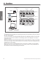
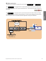

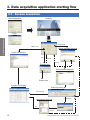
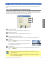


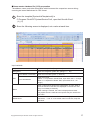

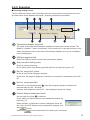

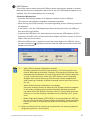
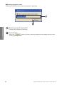

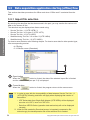
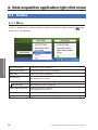
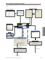
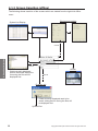
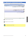
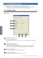
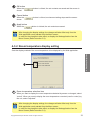
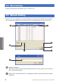

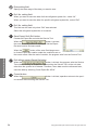

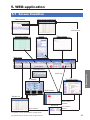
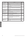
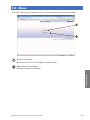
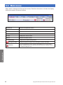
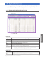
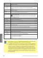
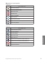

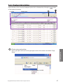
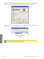
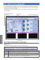
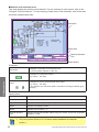

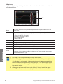

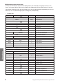
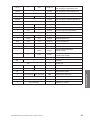

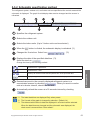
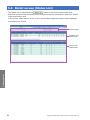
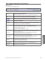
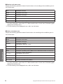
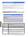
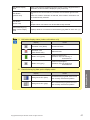
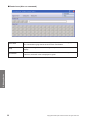
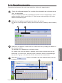
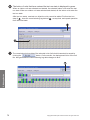
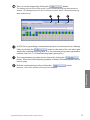
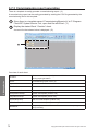
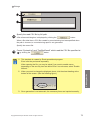
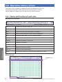
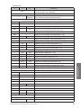
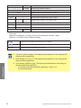
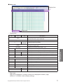
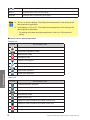
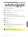
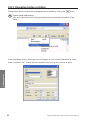
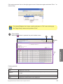
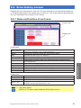
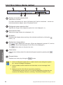
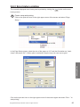
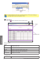
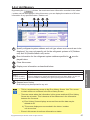
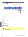
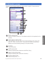
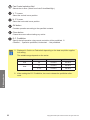
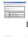

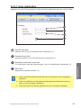
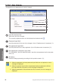
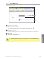

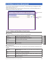
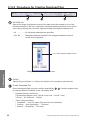


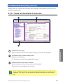

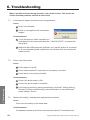
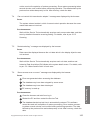


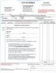


![[U2.04.05] Notice d`utilisation du modèle THM](http://vs1.manualzilla.com/store/data/006358391_1-01d1ba037f00c21b6d766ba36b13def5-150x150.png)