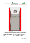
1
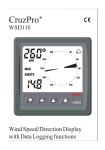
eurofire
Ekosystem AB
Gysingsstigen 28
810 20 Österfärnebo
Tel: +46 29120393
Fax: +46 29120393
[email protected]
www.ekosystem.se
Sweden
TM3007 User Manual
Revision: 2.00
TABLE OF CONTENTS
TABLE OF CONTENTS.....................................................................................................................................1
Important notes..................................................................................................................................................2
1
Description............................................................................................................................................ 2
2
User menu structure ............................................................................................................................. 3
3
Indication of errors and messages ....................................................................................................... 4
4
Genneraly ............................................................................................................................................. 5
5
Temperature settings............................................................................................................................ 5
6
Oxygen Setting ..................................................................................................................................... 5
7
Exhausttemp setting ............................................................................................................................. 5
8
Status.................................................................................................................................................... 5
9
Ignition Settings .................................................................................................................................... 6
10
Start mode ............................................................................................................................................ 6
11
Running mode ...................................................................................................................................... 6
12
Pause mode.......................................................................................................................................... 7
13
Other..................................................................................................................................................... 7
14
Stop mode ............................................................................................................................................ 7
15
Ignition sequence.................................................................................................................................. 8
Page 1 of 8
IMPORTANT NOTES
This documentation has been made solely to serve as an aid to the stoker producer to describe his
product. Techno-Matic A/S does not issue any warranty that this documentation fulfils or satisfies the
national or international demands for documenting the product since this is the duty of the individual
stoker producer. Techno-Matic A/S is, however, thankful for any comment or advice that may help to
improve this manual.
Please note: You must always turn off the power supply before actually touching anything in the
system in order to avoid dangerous situations. Only persons with a permission from the stoker
producer and with an authorization in accordance with the national legislation must carry out any
interventions/repairs in the installations.
1 DESCRIPTION
This manual is written for the stoker producer and the service technicians. In this manual adjustments
affecting very fundamental functions in the system are described. Wrong use of these functions can result in
mal function and dangerous situations. It is the duty of the stoker producer and the service technician to
make sure that the controller works correctly with the entered values. The service manual describes the
TM3007 from the software version 7.8x. The latest edition of this documentation can be required from
Techno-Matic A/S.
Please Note! If the TM3007 is switched on while the oxygen sensor is cold, the voltage supply for the
computer will be gone for about 180 seconds and the display will be without text! Then the computer
will start and text will appear again on the screen. The reason for this is that the heating element, built
into the oxygen sensor, must heat up the sensor before the correct oxygen% can be measured. If you
want to start before the end of a count-down, you can do this by pressing the STOP button once.
The service functions of the Stoker controller TM3007 are adjusted by using the various possibilities of the
built-in menu system. In order to facilitate the description thereof, we will start with a short description of the
front of the controller.
Item
START Button
STOP Button
▲ (Arrow up)
◄ (Left Arrow)
▼ (Arrow down)
► (Right Arrow)
Description
This button is used to start the stoker and to force-feeding with fuel.
This button is used for stopping the stoker.
Used for choosing an upper menu and for choosing a higher value when
setting the controller. Removes information.
Used for choosing previous menu, when you are not in the main menu.
Cancels a setting.
Used for choosing lower menu and for choosing a lower value when setting
the controller.
Used for choosing a sub-menu, choose setting and accept an entered
value.
In the menusystem the cursor ► is used for marking the menu-line on which the commands are being used.
When a parameter is being edited, the cursor will alternate between small and large ► . This is indicated with
the symbol > in this manual. The controller can be in one of the following modes: Start (Ignition), Running,
Pause, Error or Stopped.
Page 2 of 8
2 USER MENU STRUCTURE
The user menus of the TM3007 are edited as shown in the figure below (Some points are only available,
when the producer has chosen respective functions. Special functions is located in the menu “Other”
Page 3 of 8
3 INDICATION OF ERRORS AND MESSAGES
The system will indicate errors in the following situations. The alarms refer to the choice of inputs.
Alarm
Error: Hot boiler
Error: Connection
Error: Thermo Motor
Error: Lid open
Error: Hot feed. Pipe
Error: Plug is loose
Error: Hot Stok.pipe
Error: Alarm
Error: Safety
Error Thermo Motor2
Mode: Pause Ext.
Description
The boiler has stopped, because the hot boiler switch has been activated.
The boiler can be started again by pressing START after having pressed
the hot boiler thermostat again and if no other errors have been indicated.
The boiler has stopped because stoker and boiler have been separated.
The boiler can be started again by pressing START after having corrected
the error and if no other errors have been indicated.
The boiler has stopped because of a thermo drop-out on the stoker motor.
The boiler will start again, when the error has been corrected.
The boiler has stopped, because the lid of the fuel container is open. If no
other error signals are indicated, the boiler will run again when the lid has
been closed.
The boiler has stopped, because the feeding pipe has become hot. ▲ will
remove the message.
The boiler has stopped, because the plug has gone loose. The boiler can
be started again by pressing start after having corrected the error and if no
other errors have been indicated. ▲ will remove the message.
The stoker brings forward fuel, because the switch at the stoke pipe has
detected too high a temperature. The screw will run for the time entered in
**Hot stoker, “H.S. Pulse”. ▲ will remove the message .
A message which can be used for input signals, not specified in program.
▲ will remove the message .
A message which can be used for input signals, not specified in program.
▲ will remove the message .
The boiler has stopped because of a thermo drop-out on an extern motor.
The boiler will start again, when the error has been corrected. ▲ will
remove the message .
Special function, will force the controller into pause mode.
In the display will be shown a number of messages, telling the actual working mode. Beside this, the following
messages can be displayed.
User messages
** Hot stoker
** Ignition Error! **
** Power Failure! **
* Min. temp. Stop *
** Min smoke temp
** Max O2 Stop
** Profile switch
** Setting saved
** O2 Calibration OK
** Calibration Error **
** Power Failure! **
** Cooling burner
** Cleaning burner
Page 4 of 8
** Pellets failure **
Description
The boiler brings forward fuel, because the thermometer probe on the
stoker tube has detected too high a temperature. The boiler will start
automatically when the temperature of the stoker tube has fallen. ▲ will
remove the message.
The boiler has stopped, because the control could not ignite a fire.
Probably the boiler has run out of fuel. Press START to start the boiler
again. ▲ will remove the message.
The boiler has stopped because of power failure. Press START to start
the boiler again. ▲ will remove the message.
The boiler has stopped because the temperature has fallen below the
minimum temperature. Press START to start the boiler again.
The boiler has stopped because the Smoke temperature has fallen below
the minimum temperature. Press START to start the boiler again.
The boiler has stopped because the fire has burned out. Press start to
start the boiler again. ▲ will remove the message.
The boiler brings forward fuel, because the temperature sensor on the
stokerpipe has detected a too high temperature. The stoker screw will run
for as long as the temperature is too high.
The boiler has stopped, because the signal for the entry in question has
been cut. The boiler can be started again by pressing START after having
corrected the error and if no other errors have been indicated.
The boiler has stopped because stoker and boiler have been separated.
The boiler can be started again by pressing START after having
corrected the error and if no other errors have been indicated.
The boiler has stopped because of power failure. Press START to start
the boiler again. ▲ will remove the message.
The boiler has stopped and cools down in the “Cooling time”
The fan is running 100% in the “Cleaning act.” Time every 8th hour.
(Standard setting)
The refill screw has been running for too long. The silo/container is
empty.
4
GENERALLY
Press the START button to start the system, by doing this you activate the start procedure. By keeping the
START button pressed down, the stoker is activated, and material for ignition can be brought forward (as long
as START is pressed down). On systems provided with automatic ignition, the controller will make a number
of ignition attempts and after having established that there is a fire burning, the controller will switch on to
Start or Running Mode.
An extra press on START will force the controller into run mode.
th
th
th
Please notice! The 5 , 6 and 7 Chapter. (These tree Chapters aren’t always activated by the producer,
and will therefore not always be displayed.) In run mode all the selected conditions must be met so that the
installation does not stop.
5
TEMPERATURE SETTINGS
From the main menu: Temperature Press ►
•
•
•
6
to get access to the temperature settings.
Running Temp. Here you can enter the running temperature wanted.
Min temp. It is the boiler temperature entered here, together with the next, Time before stop
which indicates ”Min. temp. Stop”.
Time before stop. In running mode the boiler temperature must not be under Min. temp. for longer
than time before stop. Should this happen, the boiler will stop and the display will indicate Min.
temp. Stop. Setting must be between 1 and 120 sec.
OXYGEN SETTING
From the main menu: Press ▼ until the cursor is to the left of O2, and ► for the menu "Oxygen Setting"
• Oxygen Control. Here you can choose whether you want the oxygen control to be activated
(YES) or not (NO).
• O2. Here you can set the oxygen percentage wanted at 100% air-intake (100% running). The
TM3007 will calculate the oxygen percentage wanted at any air-intake to the effect that the
oxygen percentage will increase, if the air-intake falls.
• Max O2. Above this oxygen% the controller will tell, there is no more fire. (In combination with the
next: Time before stop
• Time before stop. The time allowed to run with an oxygen% higher than the: Max O2
• Calibrate Oxygen. By pressing YES the oxygen sensor will be calibrated. This MUST be done,
while the oxygen sensor is in open air (21% oxygen) and the system must have been switched
on for more than 3 minutes, as the sensor must be warm. Having finished the calibration, the
TM3007 display will show the following: Oxygen calibrated OK. If the TM3007 estimates that
the oxygen sensor is not functioning, the following will be shown instead: Calibration
Error! and the TM3007 will continue with the former calibration value.
Press ▼ or ▲ to alternate between the parameters. Press ► to correct a parameter (using ▼ or ▲) and
► to finish and ◄ to cancel.
7
EXHAUSTTEMP SETTING
From the main menu: Press ▼ until the cursor is to the left of Exhaust temp., and ► for the menu
"Exhausttemp setting"
• Min exhaustt. The minimum allowed exhaust temperature (smoke temperature) This
temperature + the actual water temperature, indicates In combination with the next: Time u. min.
when the fire is burned out
• Time u. min. The controller will allow, running with a lower temperature than Min exhaustt. in
this time before a stop. If it comes to a stop the message “Min. Smoke temp” will be displayed.
• Exhaustt. Max. The maximum measured exhaust temperature since the last reset. Reset is done
by pressing the ► twice.
8
STATUS
•
•
•
Page 5 of 8
Fuel used. Here you can see the total amount of fuel used, if you have tested how much the
stoker auger will give in a certain time. Should be entered below in the menus ”M. weight” and
”M. time”
Trip. The time the stoker auger has been turning. This counter can be set to zero independent of
the “Total time”
Total time. The total time the stoker auger has been running
•
•
9
M. weight The amount of fuel, the stokers auger will feed out during the time ”M. time” The
amount of fuel you can read in the ”Fuel used” is dependent of the accuracy of this measuring.
M. time. Se upper menu
IGNITION SETTINGS
If the ignition is activated, one of the three fire detecting possibilities. Fire at O2, Fire at exhaust temperature,
or Photo sensor. These settings, in the service menu, is done by the producer. The temperature/level settings
is then done by the customer.
From the main menu: Press ▼ until the cursor is to the left of "Setting", ► for the menu "Setting menu" and
► to get access to the ignition setting.
• Fire at O2. The controller will interpret it as a going fire, when the oxygen% has fallen below this
percent.
• Fire at exhaust temp. The controller will interpret it as a going fire, when the exhaust gas
temperature measured exceeds the temperature of the boiler + the temperature entered here
and/or when the Exhaust Temperature difference (rise) has been reached. (See below, E.T.
Disparity) Exhaust Temperature difference means: The controller stores the exhaust
temperature at start on ignition and the temperature must have risen by the number of degrees
entered. If you only want to use one of these settings, enter 0 at the other setting.
• E.T. Disparity. The temperature shall raise this entered value before fire is detected.
• Photo sensor: The controller will interpret it as a going fire, when the light level measured
exceeds the level entered (min. 1 max. 100).
• Stoker pulse. The producer may have chosen the stoker pulse to be editable for the user, and it
will be displayed here.
At oxygen control alternative indication of fire can be chosen: This means that the producer might have
chosen that exhaust temperature or photo sensor is used for indication of fire, whereas in normal running
mode oxygen control is being used. Press ▼ or ▲ to alternate between the parameters. Press ► to correct
a parameter (using ▼ or ▲) and ► to finish and ◄ to cancel.
10 START MODE
From the main menu: Press ▼ until the cursor is to the left of "Setting", ► for the menu "Setting menu" ▼
until the cursor is to the left of "Start Setting" and ► to see the menu Start Setting:
• Stoker pulse Decides how long each stoker pulse shall last.
• Stoker pause. Decides how long each stoker pause shall last. Press ▼ or ▲ to alternate between
the parameters. Press ► to correct a parameter (using ▼ or ▲) and ► to finish and ◄ to cancel.
11 RUNNING MODE
The controller will at any time control the speed of the blower and the pulse time of the stoker in order to
achieve the running temperature When the oxygen control is activated, the controller regulates the pulse time
of the stoker in order to achieve the oxygen percentage wanted. The actual pulse and pause on the stoker
motor can be read at the bottom of the main menu (see paragraph 2). If the oxygen control is not engaged
the controller regulates the pulse time of the stoker proportionally according to the output. From the main
menu: Press ▼ until the cursor is to the left of "Setting", ► for the menu "Setting menu" ▼ until the cursor is
to the left of "Running Setting" and ► to see the menu Running Setting:
•
•
•
•
•
Page 6 of 8
Stoker pulse. Decides how long each stoker pulse shall last. The time entered here is the
maximum time for the stoker pulse, and this is used when running in manual mode,(Without
oxygen control) It means, if oxygen control is activated, the Stoker pulse should be set longer
than without oxygen control. E.G. are the stoker pulse in manual mode set to 5 sec. The stoker
pulse in automatic, should should be set higher (40%) which is 7 sec. The TM3007 will vary the
pulse in order to achieve the oxygen percentage wanted.
Stoker pause. Decides how long each stoker pause shall last.
Stoker 2. Here the accordance between Stoker 1 and stoker 2 is set. The Percent can be
adjusted between 30 and 160%
Cleaning time. In this adjustable interval the blower will run 100% in the “Cleaning Act” time.
Cleaning Act. See the above line
•
Pause under. The performance %, below which the boiler must have operated before the
system will switch on to Pause mode and the performance beyond which the boiler must operate
before the system switches to Running mode. Must be adjusted within the range 5 -50%.
• Time under. Is used together with Pause under to adjust, when the system must switch on to
Pause mode. Must be adjusted within the range 5 – 60 minutes.
Press ▼ or ▲ to alternate between the parameters. Press ► to correct a parameter (using ▼ or ▲) and ►
to finish and ◄ to cancel.
12 PAUSE MODE
If the running temperature wanted + 6 degrees is reached, or the performance is less than what has been set
in Pause under, the system will switch on to Pause mode. During Pause a little fuel will be supplied to avoid
backburning and to maintain the fire. When the performance gets beyond what has been set in Pause under
or the temperature has dropped to 2°C below the running temperature wanted, the system will switch on to
Start Mode/Running Mode.
For the main menu: Press ▼ until the cursor is to the left of "Setting", ► for the menu "Setting menu" ▼
until the cursor is to the left of "Pause Setting" and ► to see the menu Pause Setting:
•
•
•
•
Restart. The output% where the controller will leave the pause, and go to Ignition/Startup or
normal running.
Stoker pulse Decides how long each stoker pulse shall last. (If this running temperature wanted
is exceeded by 8 degrees, the pulse will be reduced to one third). If 0 is entered here, there will
be no stoking the boiler during the pause. This setting at 0 is normal for units with automatic
ignition. At the same time normally an after-run time is entered, so the fire will be blown out and
the burner can be cooled down.
Stoker pause. Decides how long each stoker pause shall last.
After-run. Decides for how long the blower must continue to run after a stoker pulse. When the
controller switches from Running to Pause Mode, the blower will also run for this period of time.
(Setting from 0 to 900 sec.).
Press ▼ or ▲ to alternate between the parameters. Press ►
► to finish and ◄ to cancel.
to correct a parameter (using ▼ or ▲) and
13 OTHER
From the main menu: Press ▼ until the cursor is to the left of "Other", ► for the menu "Setting menu" ▼
until the cursor is to the left of "Motor 2" and ► to see the menu Other setting:
• Chalk. Here is entered the percent of the stoker on-time the chalk distributor shall run
• Ash. Here is entered the percent of the stoker on-time the ash screw shall run
• Motor 2 pulse. Decides how long each motor 2 pulse shall last.
• Motor 2 pause. Decides how long each motor 2 pause shall last. The producer may have
decided the Pause time should depend on the stoker screw’s runtime (Like the Chalk and Ash.)
• Refill time. The refill time for external refill screw. (Starts when the sensor gives a signal and
stops when the time has run out. (The sensor can be either a photocell or capacitive sensor).
• Start Refill. If you enter YES here, the refill screw will start and run for the period of time entered
in Manual Time.The period of time the refill screw must run in order to fill up.
• Start stoker. If you enter YES here, the stoker screw will start and run for the period of time
entered in Manual Time.The period of time the stoker screw must run in order to fill up the
burner. Can be stopped by pushing Stop.
• Manual Time.The period of time the stoker screw must run in order to fill up the burner.
• Profile No. Here is possible to enter 1 – 2 or 3. This parameter is used for different settings, as
example for having summer and winter settings, Pellets, chips and grain settings, or perhaps for
3 different types of burner units. The method of saving parameters is different for each stoker
producer, and will not be explained here.
14 STOP MODE
By pressing the button STOP once the system will stop and the blower will run for the period of time indicated
in “Cooling Time” under ignition. By pressing the stop button twice the blower will stop. The display will
indicate that the system is in the mode Stop. The system will stop the boiler automatically in case of errors. In
paragraph 3 you will find a list of the errors and how to handle them.
Page 7 of 8
15 IGNITION SEQUENCE
The diagram below describes the ignition sequence used.
Page 8 of 8