1
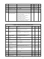
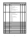
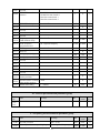
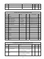
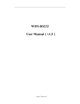
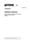
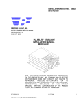
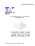
EDS780 Series
220AC 0.75KW
Series Inverter
Ver. : 1.0
Service Manual
CONTENT
1
2
3
4
5
Safety information and use notice points......................................................... 1
1.1
Safety precautions....................................................................................... 1
1.2
Use range .................................................................................................... 2
1.3
Use notice points ........................................................................................ 2
1.4
Scrap notice points...................................................................................... 4
Type and specification of the inverter.............................................................. 5
2.1
Incoming inverter inspect ........................................................................... 5
2.2
Type explanation......................................................................................... 5
2.3
Series type explanation ............................................................................... 5
2.4
Outer size and gross weight ........................................................................ 6
2.5
Basic running wiring diagram ..................................................................... 6
2.6
The inverter interface specifications ........................................................... 7
2.7
Operation and use of key board .................................................................. 8
Function parameter schedule graph ................................................................ 9
3.1
Symbol description ..................................................................................... 9
3.2
Function parameter schedule graph............................................................. 9
Troubleshooting............................................................................................... 21
4.1
Failure and countermeasure ...................................................................... 21
4.2
Failure record lookup................................................................................ 24
Maintenance .................................................................................................... 25
5.1
Routine maintenance ................................................................................ 25
5.2
Inspection and replacement of damageable parts ...................................... 25
5.3
Repair guarantee ....................................................................................... 26
5.4
Storage...................................................................................................... 26
1
Safety information and use notice points
In order to ensure the safety of your personal and equipment, before using the
inverter, please read this chapter of contents conscientiously.
1.1 Safety precautions
There are four kinds of safe relevant warnings in this service manual, they are
as follows:
notice
note
This symbol explains items that need to be paid attention to when being operated
This symbol is briefed on some useful information.
!
This symbol briefs on: If does not operate on request, may make the body
!
This symbol briefs on: If does not operate on request, may cause death,
warning
danger
injured or the equipment damaged.
severely injured or serious property loss.
(1)
(2)
(3)
(4)
!
danger
(5)
(6)
(7)
(8)
(9)
Forbid to connect U, V, W output end to AC power supply, otherwise cause
the complete damage of the inverter.
The inverter is forbidden to install on the flammables, otherwise have
danger of fire.
Don't install it in the environment with explosive gas, otherwise have
danger of causing explosion.
After connecting main loop, should carry on insulating treatment to bare
wiring end, otherwise have danger of getting an electric shock.
If being connected to the power supply, don't operate the inverter with
moist hands, otherwise have danger of getting an electric shock.
The ground terminal of the inverter must be grounded well.
Inverter being connected to power supply, please don't open cover and carry
on wiring, can connect the wire or check only after closing power for 10
minutes.
Only qualified personnel may carry on wiring and forbid leaving over any
conductive thing in machine, otherwise have danger of getting an electric
shock or causing damage of the inverter.
Inverter stored for over half a year, should be stepped up gradually with
voltage regulator first while having the electricity, otherwise have danger of
getting electric shock and explosion.
1
(1)
(2)
notice
(3)
It is prohibited that connect AC220V signal to control ends except TA, TB, TC,
otherwise have danger of damaging property.
If the inverter is damaged or without all parts, please don't install and operate it,
otherwise have danger of fire or cause personnel to be injured.
When installing, should choose a place where can endure the inverter,
otherwise have danger of injuring personnel or damaging property while falling
down.
1.2 Use range
(1) This inverter is only suitable for three phases AC asynchronous motor in general
industrial field.
(2) While applying inverter to such equipments that relate much to the life, great
property, safety devices etc., must handle cautiously, and consult with producer,
please.
(3) This inverter belongs to the control device of general industrial motor, if used in
dangerous equipment, must consider the security safeguard procedures when the
inverter breaks down.
1.3 Use notice points
(1) EDS780 series inverter is voltage-type inverter, so temperature, noise and
vibration slightly increasing compared to power source running when using,
belongs to normal phenomenon.
(2) If need to run for a long time with constant torque of low-speed, must select
motor of frequency conversion for use. Use general asynchronous AC motor
when running at a low speed, should control temperature of the motor or carry
on heat dissipation measure forcedly, so as not to burn the generator.
(3) Such mechanical device needing lubricating as the gearbox and gear wheel, etc.,
after running at a low speed for a long time, may be damaged as lubrication
result become poor, please take necessary measure in advance.
(4) When the motor running with frequency above specified, besides considering the
vibration, noise increase of the motor, must also confirm speed range of the
motor bearing and the mechanical device.
(5) For hoist and great inertia load, etc., the inverter would shut off frequently due to
2
over-current or over-voltage failure, in order to guarantee normal work, should
consider choosing proper brake package.
(6) Should switch on/off the inverter through terminal or other normal order
channels. It is prohibited that switch on/off the inverter frequently by using
strong electric switch such as magnetic control conductor, otherwise will cause
the equipment to be damaged.
(7) If need to install such switch as the magnetic control conductor, etc. between
inverter output and the motor, please guarantee the inverter is switched on/off
without output, otherwise may damage the inverter.
(8) The inverter may meet with mechanical resonance of the load within certain
range of frequency output, can set up jumping frequency to evade.
(9) Before using, should confirm the voltage of the power is within the working
voltage range allowed, otherwise should vary voltage or order special inverter.
(10) In the condition of altitude above 1000 meters, should use the inverter in lower
volume, reduce output current by 10% of specified current after each 1500
meters height increasing.
(11) Should make insulation check to the motor before using it for the first time or
after a long time placement. Please inspect with 500V voltage-type megohm
meter according to method shown as graph and insulation resistance should
not be smaller than 5 MΩ, otherwise inverter may be damaged.
(12) To forbid assembling capacitor for improving power factor or lightningproof
voltage-sensible resistance etc., otherwise will cause malfunction trip of the
inverter or damage of the parts, shown as graph 1-1.
Fig.1-1 frequency converter prohibit use of capacitor
3
(13) Remind: EDS780 inverter require long-term work at full capacity, the customer
must have an external cooling fan, or it may overheat protection fault and affect the
frequency normal life! (Inverter output current below 4A, noneed to use an external
fan.)
1.4 Scrap notice points
When disposing scrap inverter and its parts, please note:
(1)
The unit: please discard as industrial useless.
(2)
Electrolytic capacitor: when burning the inverter electrolytic capacitor in it
may explode.
(3)
Plastic: when plastic, rubber parts etc. in the inverter are burning, they may
bring bad, poisonous gas, so please be ready to safeguards.
4
2
Type and specification of the inverter
2.1 Incoming inverter inspect
(1) Check if there is damage during transportation and inverter itself has damage or fall-off
parts.
(2) Check if parts presented in packing list are all ready.
(3) Please confirm rated data of the inverter is in line with your order requirement.
Our product is guaranteed by strict quality system during manufacturing,
packing, transportation etc., please contact our company or local agent rapidly if
some careless omission or mistake arise, we’ll deal with it as soon as possible.
2.2 Type explanation
Fig. 2-1
type description
2.3 Series type explanation
Table 2-1 series type explanation
Inverter type
Rated power
(KVA)
Rated output
current(A)
Adapted motor
(KW)
EDS780-2S0007
1.8
4.7
0.75
5
2.4 Outer size and gross weight
D
H
B
A
W
Fig.2-2
Table 2-2
Inverter type
EDS780-2S0007
Outline Image
EDS780-2S0007mounting size
H
(mm)
D
(mm)
A
(mm)
B
(mm)
Fixing
aperture
(mm)
147.4 140.0
92.0
135.2
100
5
W
(mm)
2.5 Basic running wiring diagram
Fig.2-3
Basic running wiring diagram
6
2.6
The inverter interface specifications
Fig.2-4
(1) P1 terminal function description
item
run
command
Multi-function input termina
Analog value
input
symbol
name
FWD
Forward run
command
REV
Reverse run
command
Function description
Spec.
Input impedance: R=2KΩ
Forward reverse run command,
see F5.08 group double-wire and Max. input frequency: 200Hz
three-wire control function
description
Used for multi-function input
terminal, for detailed see Chapter
X1
Multi-function input 1
X2
Multi-function input 2
X3
Multi-function input 3
VCC
+5V power supply
Provide +5V power supply.
(negative pole: GND)
GND
+5V power supply
negative pole
Reference ground of analog
signal and +5V power supply
VCI
Analog value input
VCI
Accept analog voltage input
7
Max. output current: 50mA
Input voltage range:0~5V
(Input impedance:10 KΩ)
Resolution:1/1000
(2) P2 terminal function description
item
symbol
name
Function description
485A
485
communication
interface
485 difference signal positive end
communication
485B
485 difference signal negative end
spec
For standard 485
communication interface
please use twisted-pair or
STP
2.7 Operation and use of key board
Keypad is main unit for receiving command, displaying parameter. Outer
dimension of EN-KB6 is as Fig.4-2:
Fig.2-5
keypad layout sketch(EN-KB5)
8
3
Function parameter schedule graph
3.1 Symbol description
× ---- parameter can’t be changed in process of running
○ ---- parameter can be changed in process of running
* ---- read-only parameter, unmodifiable
3.2 Function parameter schedule graph
F0 –basic run function parameter group
function
name
code
Set range
0: keypad analog potentiometer setting
1: keypad digital setting
2: terminal UP/DOWN adjust setting (stored after
power off)
3: serial port setting
4: VCI analog setting (VCI-GND)
6: reserved
7: reserved
8: combination setting
9: terminal UP/DOWN adjust setting
(not stored after power off)
10:provision serial port (stored after power off)
unit
1
Factory Modificatdefault
ion
1
F0.00
Frequency input
channel selection
F0.01
Freq. digit setting Lower limit Freq.~upper limit Freq.
F0.02
Run command
channel selection
0: keypad run control
1: terminal run command control
(keypad stop command ineffective)
2: terminal run command control
(keypad stop command effective)
3: serial port run command control
(keypad stop command ineffective)
4: serial port run command control
(keypad stop command effective)
1
0
○
F0.03
Run direction
setting
1st bit: 0, forward run; 1, reserved
2nd bit: 0, forward run allowed
1, reverse run banned
rd
3
bit: REV/JOG key selection
0: as reverse run key
1: as jog key
1
100
○
F0.04
Acce/Dece mode
selection
0: linear accelerating decelerating mode
1: S curve accelerating decelerating mode
1
0
×
F0.05
S curve start
section time
10.0(%)-50.0(%)
(Acce/Dece time)
F0.05+F0.06≤90(%)
9
○
0.01Hz 50.00Hz
0.1(%) 20.0(%)
○
○
F0.06
S curve rise time
10.0(%)-70.0(%)
(Acce/Dece time)
F0.05+F0.06≤90(%)
F0.07
accelerating
decelerating time
unit
0: second
1: minute
F0.08
Acce time 1
F0.09
0.1(%) 60.0(%)
○
1
0
×
0.1-6000.0
0.1
20.0
○
Dece time 1
0.1-6000.0
0.1
20.0
○
F0.10
Upper limit freq.
Lower limit freq.-400.00Hz
0.01Hz 50.00Hz
×
F0.11
Lower limit freq.
0.00-Upper limit freq.
0.01Hz 0.00Hz
×
F0.12
Lower limit freq.
run mode
0: run at lower limit freq.
1: stop running
1
0
×
F0.13
Torque boost
mode
0: manual boost
1: automatic boost
0
○
F0.14
Torque boost
0.0-20.0(%)
0.1(%) 4.0(%)
○
F0.15
V/F curve setting
0: constant torque curve
1: degressive torque curve 1(the 2.0nd power)
2: degressive torque curve 2(the 1.7th power)
3: degressive torque curve 3(the 1.2th power)
1
0
×
F0.16
reserved
1
0
×
1
F1 –start-up, stop, brake function parameter group
Function
name
code
Set range
unit
F1.00
Start-up run mode
0: start at start-up freq.
1: first brake, then start at start-up freq.
2: reserved
F1.01
Start-up freq.
0.0-10.00Hz
F1.02
Start-up freq. duration
0.0-20.0S
F1.03
Zero freq. DC braking volt.
0-15(%)
F1.04
Zero freq. DC braking time
0.0-20.0S
F1.05
Stop mode
0: Dec stop
1: free stop
2: Dec+DC brake stop
F1.06
DC brake initiative freq.
when stop running
0.0-15.00Hz
F1.07
DC brake time when stop
running
0.0-20.0s
F1.08
DC brake voltage when stop 0-15(%)
running
1
Factory Modificatdefault ion
0
0.01Hz 0.00Hz
×
○
0.1s
0.0s
○
1
0
○
0.1s
0.0s
○
1
0
×
0.01Hz 0.00Hz
○
0.1s
0.0s
○
1
0
○
F2 –auxiliary run function parameter group
Function name
Set range
unit
10
Factory
modif-
code
F2.00
F2.01
F2.02
F2.03
F2.04
F2.05
Analog filter time
constant
Forward reverse run
dead-section time
Automatic energy
save run
AVR function
Slip frequency
compensation
Carrier wave
freq.
0.00-30.00s
0.0-3600.0s
0: no action
1: action
0: no action
1: action all the time
2: no action only during Dec
0~150(%)0-no slip frequency
compensation
1-10.0K
default
ication
0.01s
0.20s
○
0.1s
0.1s
○
1
0
×
1
0
×
1
0
×
0.1K
depend on
machine type
×
0.01Hz
5.00Hz
○
Jog run frequency
0.10-50.00Hz
F2.07
Jog Acc time
0.1-60.0s
0.1s
20.0s
○
F2.08
Jog Dec time
0.1-60.0s
0.1s
20.0s
○
F2.09
reserved
Principal subordinate
0(%)-500(%)
Machine communication
frequency provision
proportion
LED display
0000-1111
control 1
first bit: running time
0: not display
1: display
second bit: accumulative time
0: not display
1: display
third bit: input terminal status
0: not display
1: display
kilobit(fourth bit): output terminal status
0: not display
1: display
Reserved
1
0
×
1(%)
100(%)
○
1
1111
○
1
1111
○
1
0
×
F2.06
F2.10
F2.11
F2.12
F2.13
Parameter operation
control
LED 1st bit:
0: all parameter allowed to be modified
1: except this parameter,all other parameter
not allowed to be modified
2: except F0.01 and this parameter,all other
parameter not allowed to be modified
LED 2nd bit:
0: no action
1: restore default value
2: clear history failure record
LED 3rd bit:
0: lock all buttons
1: lock all buttons but not STOP key
11
F2.16
2: lock all buttons but not
,STOP key
3: lock all buttons but not RUN, STOP key
4: lock all buttons but not SHIFT, STOP key
Communication
LED first bit: baud rate selection
configuration
0: 1200BPS
1: 2400BPS
2: 4800BPS
3: 9600BPS
4: 19200BPS
5: 38400BPS
LED second bit: data format
0: 1-8-1format, no checkout
1: 1-8-1 format, even checkout
2: 1-8-1 format, odd checkout
Local address
0 - 127, 127 is broadcast address. The
inverter only receive but not send when it is
set to be 127, 0 is address for main device.
Communication overtime 0.0-1000.0s
F2.17
Local responsion delay
F2.18
1
03
×
1
1
×
0.1s
0.0s
×
0-1000ms
1ms
5ms
×
Acce time 2
0.1-6000.0
0.1
20.0
○
F2.19
Dece time 2
0.1-6000.0
0.1
20.0
○
F2.20
Acce time 3
0.1-6000.0
0.1
20.0
○
F2.21
Dece time 3
0.1-6000.0
0.1
20.0
○
F2.22
Acce time 4
0.1-6000.0
0.1
20.0
○
F2.23
Dece time 4
0.1-6000.0
0.1
20.0
○
F2.24
Acce time 5
0.1-6000.0
0.1
20.0
○
F2.25
Dece time 5
0.1-6000.0
0.1
20.0
○
F2.26
Acce time 6
0.1-6000.0
0.1
20.0
○
F2.27
Dece time 6
0.1-6000.0
0.1
20.0
○
F2.28
Acce time 7
0.1-6000.0
0.1
20.0
○
F2.29
Dece time 7
0.1-6000.0
0.1
20.0
○
F2.30
Multisection freq. 1
Lower limit freq.-upper limit freq.
0.01Hz
5.00Hz
○
F2.31
Multisection freq. 2
Lower limit freq.-upper limit freq.
0.01Hz 10.00Hz
○
F2.32
Multisection freq. 3
Lower limit freq.-upper limit freq.
Lower limit freq.-upper limit freq.
0.01Hz 20.00Hz
○
Multisection freq. 4
Lower limit freq.-upper limit freq.
0.01Hz 30.00Hz
○
Multisection freq. 5
Lower limit freq.-upper limit freq.
0.01Hz 40.00Hz
○
Multisection freq. 6
Lower limit freq.-upper limit freq.
0.01Hz 45.00Hz
○
Multisection freq. 7
Lower limit freq.-upper limit freq.
0.01Hz 50.00Hz
○
Multisection freq. 8
0.01Hz 5.00Hz
○
F2.14
F2.15
F2.33
F2.34
F2.35
F2.36
F2.37
F2.38
Reserverd
~
F2.44
F2.45
Jumping freq. 1
0.00-400.00Hz
0.01Hz
0.00Hz
×
F2.46
Jumping freq. 1 range
0.00-30.00Hz
0.01Hz
0.00Hz
×
12
F2.47
Jumping freq. 2
0.00-400.00Hz
0.01Hz
0.00Hz
×
F2.48
Jumping freq. 2 range
0.00-30.00Hz
0.01Hz
0.00Hz
×
F2.49
Jumping freq. 3
0.00-400.00Hz
0.01Hz
0.00Hz
×
F2.50
Jumping freq. 3 range
0.00-30.00Hz
0.01Hz
0.00Hz
×
F2.51
Setting run time
0-65535 hours
1
0
○
F2.52
Accumulative run time
0-65535 hours
1
0
*
F2.53
RS485communication
frame format selection
0: a ASCII frame of 14 byte or 18 byte
1: a hex frame of 8 byte or 10 byte, original
response not changed
2: a hex frame of 8 byte or 10 byte, 12
command has no response
3: a hex frame of 8 byte or 10 byte, 14
command has no response
4: a hex frame of 8 byte or 10 byte, both 12
and 14 command have no response
1
0
×
F3 group –closed-loop run function parameter group
Function
name
code
F3.00 Closed-loop run
control selection
Set range
Factory
default
modification
1
0
×
1
1
○
1
1
○
0.01
0.00
○
unit
0: closed-loop control ineffective
1: PID closed-loop control effective
2: reserved
0: digital provision
1: VCI analog 0-5V voltage provision
2: reserved
3: keypad analog potentiometer provision
0: VCI analog input voltage 0-5V
1: reserved
F3.01
Provision channel
selection
F3.02
Feedback channel
selection
F3.03
Specified value digital
setting
F3.04
Minimum specified value 0.0-maximum specified value; percentage
relative to 10.00V
0.1(%)
0.0(%)
○
F3.05
feedback value
responding to
minimum specified
0.0(%)-100.0(%)
0.1(%)
0.0(%)
○
Minimum specified value-100.0(%)
0.1(%) 100.0(%)
○
0.0(%)-100.0(%)
0.1(%) 100.0(%)
○
0.00-10.00V
value
F3.08
maximum specified
value
feedback value
responding to
maximum specified
value
proportion gain Kp
0.000-9.999
0.001
0.050
○
F3.09
Integral gain Ki
0.000-9.999
0.001
0.050
○
F3.10
Differential gain Kd
0.000-9.999
0.001
0.050
○
F3.11
Sampling cycle T
0.01-1.00s
0.01s
0.10s
○
F3.06
F3.07
13
F3.12
Deviation margin
F3.13
Integral separation PID
adjusting threshold
Closed-lop preset
frequency
Closed-loop preset
frequency holding
time
Reserved
F3.14
F3.15
F3.16
0.0-20.0(%)percentage relative to 10.00V
0.1(%)
0.0-100.0%
0.1(%) 100.0(%)
○
0-upper limit frequency
0.01Hz
0.00Hz
○
0.1s
0.0s
○
1
0
○
1
1
○
0.01Hz
0.00 Hz
○
15
○
100
○
0.0-6000s
2.0(%)
○
~
F3.26
F3.27
F3.28
F3.29
F3.30
F3.31
Closed-loop adjusting
characteristic
LED initial
supervision parameter
selection
Zero freq. braking freq.
at starting
Failure relay TA, TC
function selection
VCI analog input gain
0: Forward function
1: Reverse function
0: set frequency
1: output frequency
2: output current
3: output voltage
4: DC bus bar voltage
5: motor speed
6: heat sink temperature
7: run time
8: accumulative run time
9: input terminal status
10: output terminal status
11: analog input VCI/PID provision
0.00Hz-15.00Hz
0: inverter running(RUN)
1: frequency arriving signal(FAR)
2: frequency level detect signal (FDT1)
3: reserved
4: overload warning alarm signal (OL)
5: output frequency reach high limit(FHL)
6: output frequency reach low limit(FLL)
7: inverter under voltage blockage stop (LU)
8: external failure stop-running(EXT)
9: inverter zero speed running
10: PLC running
11: simple PLC section running finished
12: PLC finish a cycle running
13: reserved
14: inverter ready to run (RDY)
15: inverter failure
16: traverse high and low limit restriction
17: interior counter reach final value
18: interior counter reach specified value
19: set run time arriving
20: interior timing arriving
21~24: reserved
0-800%
14
F4 –simple PLC function parameter group
Function
name
code
F4.00 Simple PLC
running setting
Set range
F4.02
LED first bit:
0: no action
1: stop after single circulation
2: keep final value after single circulation
3: consecutive circulation
LED second bit:
0: start again from first section
1: continue to run at mid-section frequency
LED third bit: PLC run time unit
0: second
1: minute
Section 1 setting
000-621
LED first bit: frequency setting
0: multi-section freq. i (i=1~7)
1: freq. determined by F0.00 function code
LED second bit: run direction selection
0: forward run
1: reverse run
2: determined by run command
LED third bit: Acc/Dec time selection
0: Acc/Dec time 1
1: Acc/Dec time 2
2: Acc/Dec time 3
3: Acc/Dec time 4
4: Acc/Dec time 5
5: Acc/Dec time 6
6: Acc/Dec time 7
Section 1 run time 0-6000.0
F4.03
Section 2 setting
F4.04
Section 2 run time 0-6000.0
F4.05
Section 3 setting
F4.06
Section 3 run time 0-6000.0
F4.07
Section 4 setting
F4.08
Section 4 run time 0-6000.0
F4.09
Section 5 setting
F4.10
Section 5 run time 0-6000.0
F4.11
Section 6 setting
F4.12
Section 6 run time 0-6000.0
F4.13
Section 7 setting
F4.14
Section 7 run time 0-6000.0
F4.01
Factory
default
modifi
cation
1
000
×
1
000
○
0.1
10.0
○
1
000
○
0.1
10.0
○
1
000
○
0.1
10.0
○
1
000
○
0.1
10.0
○
1
000
○
0.1
10.0
○
1
000
○
0.1
10.0
○
1
000
○
0.1
10.0
○
unit
000-621
000-621
000-621
000-621
000-621
000-621
15
F5 –terminal correlative function parameter group
Function
name
code
F5.00 Input terminal X1
function selection
F5.03
Input terminal X2
function selection
Input terminal X3
function selection
reserved
F5.04
reserved
F5.05
reserved
F5.06
reserved
F5.01
F5.02
Set range
unit
0: leave control terminal unused
1: multi-section speed control terminal
2: multi-section speed control terminal
3: multi-section speed control terminal
4: multi-section speed control terminal
5: external forward run jog control
6: external reverse run jog control
7: Acc/Dec time option terminal 1
8: Acc/Dec time option terminal 2
9: Acc/Dec time option terminal 3
10: external device failure input
11: external reset input
12: free stop input
13: external stop-running order
14: stop DC braking input command DB
15: inverter run banned
16: frequency increasing control (UP)
17: frequency degression control (DOWN)
18: Acc/Dec ban command
19: three-line run control
20: closed-loop ineffective
21: PLC ineffective
22: simple PLC pause control
23: PLC stop status reset
24: frequency provision channel option 1
25: frequency provision channel option 2
26: frequency provision channel option 3
27: frequency switched to CCI
28: command switched to terminal
29: run command channel option 1
30: run command channel option 2
31: run command channel option 3
32: traverse jump-in
33: external interruption input
34: interior counter reset end
35: interior counter triggering end
36: interior timer reset end
37: interior timer triggering end
38: reserved
Same as above
Same as above
1
Factory
default
modifi
cation
0
×
×
×
×
×
16
F5.07
F5.08
reserved
FWD/REV run mode
selection
F5.09
UP/DOWN velocity
F5.10
Reserved
F5.11
reserved
F5.12
reserved
F5.13
F5.16
reserved
Frequency arriving
(FAR) checkout scope
FDT1 (frequency
level) electric level
FDT1 lag
F5.17
Reserved
F5.18
Analog output (AO) gain
F5.19
Analog output (AO) offset 0.00-10.00V
F5.20
reserved
F5.21
reserved
F5.22
reserved
F5.23
reserved
F5.24
reserved
F5.14
F5.15
F5.25
F5.26
F5.27
0: double-line control mode 1
1: double-line control mode 2
2: three-line control mode 1
3: three-line control mode 2
0.01-99.99Hz/s
1
0
0.01Hz/s 1.00Hz/s
×
○
1
0
×
0.00-50.00Hz
0.01Hz
5.00Hz
○
0.00-high limit frequency
0.01Hz
10.00Hz
○
0.00-50.00Hz
0.01Hz
1.00Hz
○
1
0
○
0.01
1.00
○
0.01
0.00
○
1
0
○
1
0
○
0.1
60.0
○
Factory
default
modifi
cation
0.00-2.00
Set interior counting value 0--9999
reaches provision
Specified interior counting 0--9999
value reaches provision
Interior timer setting
0.1-6000.0s
F6 –traverse special function parameter group
Function
code
name
Set range
unit
F6.00 ~ Reversed
F6.07
F7–frequency provision function parameter group
Function
code
name
Set range
unit
Factory
default
modifi
cation
F7.00
VCI min. provision
0.00-F7.02
0.01V
0.00V
○
F7.01
VCI min. provision corresponding freq.
0.00-high limit frequency
0.01Hz
0.00Hz
○
17
F7.02
VCI max. provision
0.00-10.00V
0.01V
F7.03
VCI max. provision corresponding freq.
0.00-high limit frequency
0.01 Hz 50.00Hz
9.90V
○
○
F7.04~ Reversed
F7.17
F8–motor and vector control parameter group
Function
code
name
Set range
Factory default
modifi
cation
1V
Depend on device type
×
0.1A
Depend on device type
×
unit
F8.00
reserved
F8.01
Motor rated voltage
1-480V
F8.02
Motor rated current
0.1-999.9A
F8.03
Motor rated frequency
1.00-400.00Hz
0.01Hz
Depend on device type
×
F8.04
Motor rated speed
1-9999r/min
1r/min
Depend on device type
×
F8.05
Motor pole
2-14
2
Depend on device type
×
F8.06
Motor rated power
0.1-999.9KW
0.1
Depend on device type
×
F8.07
reserved
F8.08
reserved
F8.09
reserved
F8.10
reserved
F8.11
reserved
F8.12
reserved
F8.13
reserved
F8.14
reserved
F8.15
reserved
F8.16
Frequency display offset
0.00Hz-2.00Hz
0.01Hz
0.20Hz
○
F8.17
reserved
F9 –protection correlative function parameter group
Function
code
name
F9.00
reserved
F9.00
Instantaneous power
off restarting latency
time
F9.01
Failure self-renew
times
Set range
Factory
default
modifi
cation
0.1S
0.0S
×
1
0
×
unit
0.0-10.0S
0 indicates ineffective power off restarting
Remark: no automatic reset function for
overload and overheating
0-10
0 shows no automatic reset function
Remark: no automatic reset function for
overload and overheating
18
F9.02
Failure self-renew interval
0.5-20.0S
F9.03
Motor overload
protection mode selection
Motor overload
protection coefficient
0: no action
1: inverter close off output
20.0-120.0(%)
20-200(%)
1(%)
130(%)
○
0.0-20.0s
0.1s
5.0s
○
F9.07
Overload warning
alarm checkout level
Overload warning
Alarm Delay time
Overvoltage stall selection
1
1
×
F9.08
Overvoltage stall point
0: ban
1: allow
120-150(%)
1(%)
140(%)
○
F9.09
Reversed
F9.10
Reversed
F9.11
Reversed
F9.04
F9.05
F9.06
0.1S
5.0S
×
1
1
×
0.1(%) 100.0(%)
×
Fd –failure record function parameter group
Function
code
Set range
Fd.00
Previous one time failure record
Previous one time failure record
1
0
*
Fd.01
Previous two time failure record
Previous two time failure record
1
0
*
Fd.02
Previous three time failure record
Previous three time failure record
1
0
*
Fd.03
Previous four time failure record
Previous four time failure record
1
0
*
Fd.04
Previous five time failure record
Previous five time failure record
1
0
*
Fd.05
Previous six time failure record
Previous six time failure record
1
0
*
Fd.06
Set freq. of previous failure
Set freq. of previous failure
0.01Hz
0
*
Fd.07
output freq. of previous failure
output freq. of previous failure
0.01Hz
0
*
Fd.08
output current of previous failure
output current of previous failure
0.1A
0
*
Fd.09
output voltage of previous failure
output voltage of previous failure
1V
0
*
Fd.10
DC bus-bar voltage of previous failure
DC bus-bar voltage of previous
failure
1V
0
*
Fd.11
Load motor speed of previous failure
1(r/m)
0
*
1℃
0
*
0
*
0
*
Fd.12
Fd.13
Fd.14
Load motor speed of previous
failure
Module temperature of previous failure
Module temperature of previous
failure
Input terminal status of previous failure
Input terminal status of previous
failure
Accumulative run time of previous failure Accumulative run time of previous
failure
FF –password and manufacturer function parameter group
19
unit
Factory modifi
default cation
name
Function
code
unit
Factory modifi
default cation
name
Set range
FF.00
User password
0000-9999
1
0000
×
FF.01
FF.02
FF.0X
Manufacturer password
0000-9999
1
0000
×
Manufacturer’s special parameter
C –supervision function parameter group
Function
code
Factory modifi
default cation
name
Set range
unit
C.00
Set frequency
Current set frequency
0.01HZ
C.01
Output freq.
Current output freq.
0.01HZ
*
C.02
Output current
Virtual value of current output current
0.1A
*
C.03
Output voltage
Virtual value of current output voltage
1V
*
C.04
DC bus-bar voltage
Current
1V
*
C.05
Load motor speed
1(r/m)
*
C.06
Module temperature
Product of output frequency and load motor
speed emendation factor
IGBT heat sink temperature
1℃
*
C.07
Run time
Inverter electrification run time
1h
*
C.08
accumulative run time Inverter accumulative run time
1h
*
C.09
Input terminal status
――
*
C.10
output terminal status Switch value output terminal status
――
*
C.11
Analog input VCI
Analog input value of VCI
V
*
C.12
Analog input YCI
Analog input value of YCI
V
*
C.13
Reserved
C.14
Reversed
DC bus-bar voltage
Switch value input terminal status
20
4
Troubleshooting
4.1 Failure and countermeasure
Possible failure types in EDS780 are shown in Table 4-1 and failure code is from
E001 to E023. Some failure code is reserved for intelligent automatic diagnosis
function which will be executed continuously in future. When failure takes place in
the inverter, the user should check according to note of this table firstly and record
failure phenomena detailedly. Please contact our after-sale service and technical
support Department or agent in your local place when technical service is needed.
Table 4-1
failure
code
E001
E002
failure type
failure type and the countermeasure
possible reason
overcurrent during Accelerating time is too short
accelerating
process
Improper V/F curve
E004
Prolong accelerating time
Adjust V/F curve setting,adjust
manual torque boost or change to
automatic torque boost
Restart rotating motor
Set speed checking restart
function
Low power source
voltage
Check input power supply
Too small power of the
inverter
Choose inverter with high-power
overcurrent during Decelerating time is too
short
decelerating
process
Have potential energy
load or big inertia load
Power of inverter is a bit
small
E003
countermeasure
overcurrent during Load change suddenly or
constant
speed Have unwonted
process
phenomena
Prolong decelerating time
Increase braking power of
external energy consumption
braking subassembly
Choose inverter with high-power
Check or reduce break of the load
Accel/Decel time is set
to too short
Prolong accelerating decelerating
time properly
low power source
voltage
Check input power supply
Power of inverter is a bit small
Choose inverter with high-power
overvoltage
Unwonted input voltage
during accelerating Accel time is set to too short
process
Restart rotating motor
Check input power supply
Prolong accelerating time
properly
Set speed checking restart
function
21
E005
E006
overvoltage during Decelerating time is too short
decelerating
Have potential energy
process
load or big inertia load
Prolong decelerating time
Overvoltage
Unwonted input voltage
during
constant Accel/Decel time is set
speed process
to too short
Check input power supply
Increase braking power of
external energy consumption
braking subassembly
Prolong accelerating decelerating
time properly
Input voltage change
abnormally
Assemble reactor
Load inertia is a bit big
Use energy consumption
subassembly
E007
controlpower
Unwonted input voltage
supply overvoltage
Check input power supply or look for service
E008
Inverter overload
Accel time is set to too
short
Prolong accelerating time
DC injection braking is
too big
Reduce DC injection braking
current,prolong braking time
improper V/F curve
Adjust V/F curve and torque
boost
Restart rotating motor
Set speed checking restart
function
power source voltage is
too low
check power source voltage
Load is too big
Choose inverter with high-power
improper V/F curve
Adjust V/F curve and torque
boost
power source voltage is
too low
check power source voltage
General motor run at low
speed with big load
Can choose frequency conversion
motor for long time low speed
run
motor overload
protection factor set
incorrectly
to set motor overload protection
factor correctly
E009
Motor overload
motor blocked up or load change Check the load
too suddenly and
quickly
E010
E011
inverter
heating
reserved
over Air-path blocked
To clear air-path or improve
ventilation condition
Ambient temperature is too high
Improve ventilation condition,
lower carrier frequency
Run with large load long time
Use fan outside to radiate
reserved
reserved
22
E012
reserved
reserved
E013
Inverting module Transient
protection
inverter
reserved
overcurrent
of
the Refer to countermeasure for
overcurrent
phase to phase short
circuit or earthing short
circuit of output 3 phase
wiring again
Air-path blocked or fan damaged
To clear air-path or replace the
fan
Ambient temperature is too high
Lower ambient temperature
Connecting wire or insert on Check and connect the wire again
control board
loose
Unwonted current wave caused Check wiring
by missing
output phase etc.
E014
external
failure
Assistant power supply
damaged and drive
voltage lacking
Look for service from
manufacturer or agent
Unwonted control board
Look for service from
manufacturer or agent
device use sudden stop
STOP
Look up operation mode
key in non-keypad run mode
Use sudden stopkey
Set running parameter correctly
under condition of stall
Sudden stop terminal for external Open external failure terminal after external
failure closed
failure is settled
E015
reserved
reserved
reserved
E016
RS485
communication
failure
Baud rate set improperly
set Baud rate properly
Serial port
communication error
press
key to reset, look for service
Failure warning
parameter set improperly
Modify F2.16, F2.17
Check if upper device work and
wiring is correct
reserved
E017
reserved
Upper device doesn’t
work
reserved
E018
reserved
reserved
reserved
E019
Under voltage
Under voltage
check spot input voltage
23
E020
System
disturbance
Serious disturbance
Reset by pressing
key or add mains filter at power
supply input side
CPU read
and write wrongly
Reset by the key-press, look for
service
E021
reserved
reserved
reserved
E022
reserved
reserved
reserved
E023
P.OFF
2
E PROM read and Mistake take place when
write wrongly
read or write control
parameter
Reset by pressing
Under voltage
check spot input voltage
Look for service from
manufacturer or agent
Under voltage
4.2 Failure record lookup
This series inverter can record latest 6 failure code and inverter run parameter
of the last failure, to search these informations can redound to finding out reason of
the failure.
Failure information is all stored in Fd group parameter,please enter into Fd
group parameter to see about information by referring to keypad operation method.
code
content
code
Fd.08
Content
Fd.00
previous one failure record
Fd.01
previous two failure record
Fd.09
output volt. at previous failure
Fd.02
previous three failure record
Fd.10
DC bus-bar vlot. at previous failure
Fd.03
previous four failure record
Fd.11
load motor speed at previous failure
Fd.04
previous five failure record
Fd.12
module temp. at previous failure
Fd.05
previous six failure record
Fd.13
input end state at previous failure
Fd.06
set freq. at previous failure
Fd.14
Accu. runtime at previous failure
Fd.07
output freq. at previous failure
—
24
output current at previous failure
—
5
Maintenance
5.1 Routine maintenance
You must assemble and operate it according to demand listed in this《service
manual》strictly when you use inverter. During run state, temperature, humidity,
vibration and aging parts may affect it. To avoid this, it is recommended to perform
routine inspections.
Table 5-1 Daily inspection items
period
daily
Inspection
periodic
Run state
√
parameter
Cooling
√
Criterion
(1)output current
(1)within range of rated value
(2)output voltage
(2)within range of rated value
(3)inside temp.
(3)temp. increment < 35
(1)installing ambient
(1)good ventilation, unblocked air-path
(1)heating
(1)no abnormality
(2)noise
(2)even
(1) vibration, heating
(1)vibration balanced, proper wind temp.
(2)noise
(2) without abnormal sound
(3)fixation of lead, terminal
(3)fixed screw don’t loose
(1)temperature, humidity
(1)-10 ~+40
system
√
Motor
√
√
Inspection content
item
Inverter
40 ~50 used in lower volume
Run
ambient
or execute compulsory heat dissipating
(2)dust, water and leakage
(2)no water leakage imprint, no dust
(3)gas
(3)no peculiar smell
Recommend to inspect with following instrument:
Input voltage: electric voltmeter;output voltage: rectifying voltmeter;input
output current: pincers ammeter.
5.2 Inspection and replacement of damageable parts
Some component parts in the inverter will be abraded or bear descending
performance for long-term usage,to assure that the inverter can run stably and
reliably, it is recommended to perform defending maintenance and replace
corresponding parts if necessary.
25
(1) filter electrolyte capacitance
When frequent-changing load causes increasing pulsant current and aging
electrolyte under high ambient temperature, the electrolyte capacitance may be
damaged and here should replace it.
5.3 Repair guarantee
(1) Within 18 months from purchasing date, if failure caused by inverter itself takes
place under normal conservation and usage, we will provide free repair service.
(2) We will take some upkeep if one of following situations takes place within
period of repair guarantee.
a. If did not use the inverter according to《service manual》strictly or did not use
it under ambient demanded in《service manual》, which cause failure.
b. Failure caused by applying the inverter to non-normal function;
c. Failure caused by self-repair, refit which is not already allowed;
d. Damage caused by bad keeping, falling down from high place or other
extrinsic factor after purchasing the inverter;
e. Failure caused by natural disaster or its reason such as unwonted voltage,
thunderbolt, water fog, fire, salt corroding, gas corroding, earthquake and
storm etc.;
f. Make bold to tear up product logo (such as: nameplate etc.); Body serial
number don’t accord with that in repair guarantee card.
(3) We calculate service fee based on actual cost, which is subject to contract if any.
(4) You can contact the agent and also our company directly if you have questions.
After repair guarantee period, we shall also provide lifetime charged repair
service for our products.
5.4 Storage
The user must pay attention to following points for temporary storage and
long-term storage after purchasing the inverter:
(1) Avoid storing the inverter in high temperature, moist place and place of dust,
metal powder and assure good ventilation.
(2) Longtime storage will cause electrolyte capacitance of low quality, so must
assure that it’s electrified for one time within 2 years and electrification time is
not shorter than 5 hours and input voltage must be increased to rated value
gradually by voltage adjustor.
26