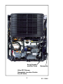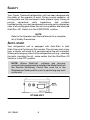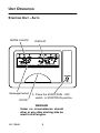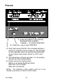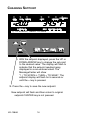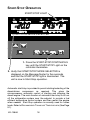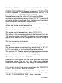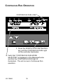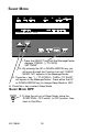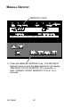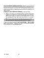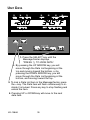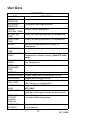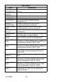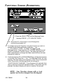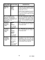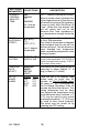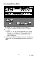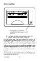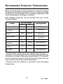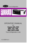
1
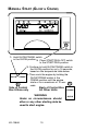
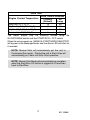
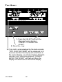
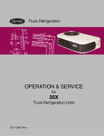
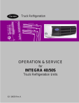
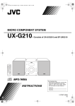
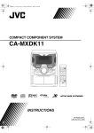
R -20.0 Trailer And Rail Refrigeration +34.5° F ↑↓ TO SCROLL, THEN = TO SAVE OPERATOR’S MANUAL for Ultima 53, Ultra/UltraXL, Extra, Ultra/Ultima XTC With Advancet Microprocessor Trailer And Rail Refrigeration Units 62--10646 Rev G OPERATOR’S MANUAL TRAILER AND RAIL REFRIGERATION UNITS With Advance Microprocessor Ultima 53 Ultra and Ultra XL Extra Ultra XTC And Ultima XTC CONTENTS Page Software . . . . . . . . . . . . . . . . . . . . . . . . . . . . . . . . . . . . . . . . . . . . . . 2 Unit Identification . . . . . . . . . . . . . . . . . . . . . . . . . . . . . . . . . . . . . . . 4 Safety . . . . . . . . . . . . . . . . . . . . . . . . . . . . . . . . . . . . . . . . . . . . . . . . 6 Unit Operation . . . . . . . . . . . . . . . . . . . . . . . . . . . . . . . . . . . . . . . . . 8 Manual Start . . . . . . . . . . . . . . . . . . . . . . . . . . . . . . . . . . . . . . . . . . 10 Pretrip . . . . . . . . . . . . . . . . . . . . . . . . . . . . . . . . . . . . . . . . . . . . . . . 12 Changing Setpoint . . . . . . . . . . . . . . . . . . . . . . . . . . . . . . . . . . . . . 14 Start-Stop Operation . . . . . . . . . . . . . . . . . . . . . . . . . . . . . . . . . . . 16 Continuous Run Operation . . . . . . . . . . . . . . . . . . . . . . . . . . . . . . 18 Sleep Mode . . . . . . . . . . . . . . . . . . . . . . . . . . . . . . . . . . . . . . . . . . 20 Manual Defrost . . . . . . . . . . . . . . . . . . . . . . . . . . . . . . . . . . . . . . . . 22 Trip Start . . . . . . . . . . . . . . . . . . . . . . . . . . . . . . . . . . . . . . . . . . . . . 24 Alarm List - View Alarms . . . . . . . . . . . . . . . . . . . . . . . . . . . . . . . 26 Unit Data . . . . . . . . . . . . . . . . . . . . . . . . . . . . . . . . . . . . . . . . . . . . . 30 Functional Change (Parameters) . . . . . . . . . . . . . . . . . . . . . . . . 34 Two--Way Remote Communication . . . . . . . . . . . . . . . . . . . . . . 40 Remote Monitoring Control Box . . . . . . . . . . . . . . . . . . . . . . . . . 42 Mode Switch . . . . . . . . . . . . . . . . . . . . . . . . . . . . . . . . . . . . . . . . . . 43 Restart And Battery Disconnect . . . . . . . . . . . . . . . . . . . . . . . . . 44 Resetting The Control Box . . . . . . . . . . . . . . . . . . . . . . . . . . . . . . 45 Momentary Shut Off Switch . . . . . . . . . . . . . . . . . . . . . . . . . . . . . 46 IntelliSet . . . . . . . . . . . . . . . . . . . . . . . . . . . . . . . . . . . . . . . . . . . . . 47 Current IntelliSet Selection . . . . . . . . . . . . . . . . . . . . . . . . . . . . . 48 Changing IntelliSets . . . . . . . . . . . . . . . . . . . . . . . . . . . . . . . . . . . 49 Stopping Unit . . . . . . . . . . . . . . . . . . . . . . . . . . . . . . . . . . . . . . . . . 50 Recommended Transport Temperatures . . . . . . . . . . . . . . . . . . 51 Pre-Trip Inspection . . . . . . . . . . . . . . . . . . . . . . . . . . . . . . . . . . . . 52 Product Loading . . . . . . . . . . . . . . . . . . . . . . . . . . . . . . . . . . . . . . . 54 Problems . . . . . . . . . . . . . . . . . . . . . . . . . . . . . . . . . . . . . . . . . . . . . 56 Fuses . . . . . . . . . . . . . . . . . . . . . . . . . . . . . . . . . . . . . . . . . . . . . . . . 58 Unit Maintenance . . . . . . . . . . . . . . . . . . . . . . . . . . . . . . . . . . . . . 60 Unit Maintenance Schedule . . . . . . . . . . . . . . . . . . . . . . . . . . . . . 61 Priming Fuel System . . . . . . . . . . . . . . . . . . . . . . . . . . . . . . . . . . . 63 Emergency Road Service . . . . . . . . . . . . . . . . . . . . . . . . . . . . . . 64 OPERATOR’S MANUAL This guide has been prepared for the operator of units supplied with the Advance Microprocessor: Ultima 53, Ultra and Ultra XL, Extra, and Ultra XTC and Ultima XTC Carrier Transicold diesel trailer and rail refrigeration units. It contains basic instructions for the daily operation of the refrigeration unit as well as safety information, troubleshooting tips, and other information that will help you to deliver the load in the best possible condition. Please take the time to read the information contained in this booklet and refer to it whenever you have a question about the operation of your Carrier Transicold unit. Your refrigeration unit has been engineered to provide long, trouble-free performance when it is properly operated and maintained. The checks outlined in this guide will help to minimize overthe-road problems. In addition, a comprehensive maintenance program will help to insure that the unit continues to operate reliably. Such a maintenance program will also help to control operating costs, increase the unit’s working life, and improve performance. This guide is intended as an introduction to your unit and to provide general assistance when needed. More comprehensive information can be found in the Operation & Service Manual for your unit. This manual can be obtained from your Carrier Transicold dealer. When having your unit serviced, be sure to specify genuine Carrier Transicold replacement parts for the highest quality and best reliability. At Carrier Transicold, we are continually working to improve the products that we build for our customers. As a result, specifications may change without notice. 1 62--10646 SOFTWARE It is strongly advised that all units be upgraded to Advance Software Version 04.03.00. This manual is written for Software version 04.03.00 and above. NOTE Once 04.03.00 is installed into an Advance Controller, it will no longer be possible to load any versions of 03.xx.xx software into that microprocessor. Future version releases may be loaded as they are released. NOTE Certain new software features contained within the 04.03.00 version will not be functional without the ReeferManager PC program. It is recommended that ReeferManager be used when setting Functional Parameters, Configurations, IntelliSets, etc. once 04.03.00 has been installed. 62--10646 2 UNIT IDENTIFICATION Each unit is identified by a decal attached to the frame of the unit. This decal is on the roadside vertical frame post behind the roadside side door. The decal identifies the complete model number of the unit, the serial number, the type of refrigerant and quantity, and the date the unit was placed in service. If a problem occurs, please refer to the information on this decal, and make a note of the model and serial number before calling for assistance. This information will be needed when you contact a technician or Carrier Transicold Service Engineer so that they may properly assist you. 62--10646 4 Serial Number and Bar Code Nameplate Ultra XTC Shown Nameplate Location Similar For All Units 5 62--10646 SAFETY Your Carrier Transicold refrigeration unit has been designed with the safety of the operator in mind. During normal operation, all moving parts are fully enclosed to help prevent injury. During all pre-trip inspections, daily inspections, and problem troubleshooting, you may be exposed to moving parts; please stay clear of all moving parts when the unit is in operation and when the Start/Run--Off Switch is in the START/RUN position. NOTE Refer to the Operation and Service Manual for a complete list of Safety Precautions. AUTO-START Your refrigeration unit is equipped with Auto-Start in both Start--Stop and Continuous Run modes. The unit may start at any time, a buzzer will sound for 5 seconds before the unit is started. When performing any check of the refrigeration unit (e.g., checking the belts, checking the oil), make certain that the Start/Run--Off Switch is in the OFF position. NOTE: Where DataTrakt software and two--way communication equipment is installed, the Mode Switch on the Remote Monitoring Control Box must be in the Maintenance Mode position prior to performing any work on the unit. RT2000 UNIT 62--10646 6 ENGINE COOLANT The engine is equipped with a pressurized cooling system. Under normal operating conditions, the coolant in the engine and radiator is under high pressure and is very hot. Contact with hot coolant can cause severe burns. Do not remove the cap from a hot radiator; if the cap must be removed, do so very slowly in order to release the pressure without spray. REFRIGERANTS The refrigerant contained in the refrigeration system of your unit can cause frostbite, severe burns, or blindness when in direct contact with the skin or eyes. For this reason, and because of legislation regarding the handling of refrigerants during system service, we recommend that, whenever your unit requires service of the refrigeration system, you contact your nearest Carrier Transicold authorized repair facility for service. BATTERY This unit is equipped with a lead-acid type battery. The battery normally vents small amounts of flammable hydrogen gas. Do not smoke when checking the battery. A battery explosion can cause serious physical harm and/or blindness. 7 62--10646 UNIT OPERATION STARTING UNIT - AUTO MODE LIGHTS -20.0 MessageCentert DOOR DISPLAY + 3 4 .5 ° F 1. Place the START/RUN - OFF switch to START/RUN position. WARNING Under no circumstances should ether or any other starting aids be used to start engine. 62--10646 8 The microprocessor controller will run a self test. All of the mode lights will illuminate, all of the segments on the display will be turned on, and all of the Liquid Crystal Displays (LCDs) in the message center will be turned on. The display will then show the setpoint temperature on the left and the box temperature on the right. The last character (after the degree symbol) shows the temperature units as F (Fahrenheit) or C (Celsius). The MessageCenter will show “STATUS OK” or other user--defined message unless there is an alarm stored in the controller. If there is an alarm stored in the controller, an alarm message will be displayed on the MessageCenter and the Alarm LED will flash for 5 seconds. The glow plugs will energize, the buzzer will sound, and the diesel engine will start. 9 62--10646 MANUAL START (GLOW & CRANK) -20.0 3 4 .5 ° F 1. Hold GLOW/CRANK switch in the GLOW position.2. Place START/RUN--OFF switch to the START/RUN position. 3. Continue to hold GLOW/CRANK switch in the GLOW position for up to 15 seconds, based on the temperature table below. GLOW CRANK 4. Then crank the engine by holding the GLOW/CRANK switch in the CRANK position until the engine starts or for a maximum of 10 seconds. Side of Control Box Ultima only Back of Control Box All Other Units WARNING Under no circumstances should ether or any other starting aids be used to start engine. 62--10646 10 CRANK GLOW Glow Time Glow Time in Seconds Engine Coolant Temperature TV/Short DI/ (Default) Long Less than 32_F (0_C) 15 55 33_F to 50_F (1_C to 10_C) 10 40 51_F to 77_F (11_C to 25_C) 5 25 Greater than 78_F (26_C) 0 10 The diesel engine may be manually started using the GLOW/CRANK switch and the START/RUN -- OFF switch. When the micro powers up, “MANUAL START MODE SELECTED” will appear in the MessageCenter and the Alarm LED will blink for 5 seconds. NOTE: Manual Start will automatically put the unit in Continuous Run mode. Placing the unit in Start--Stop will automatically put it back into Auto Start operation. NOTE: Manual Start Mode will automatically be cancelled when the Start/Run--Off Switch is toggled to Off and then back to Start/Run. 11 62--10646 PRETRIP -20.0 +34.5° F T EST #1 1. Press the SELECT key until the MessageCenter displays “PRESS = TO START PRETRIP”. 2. Press the = key to start PRETRIP. 3. Verify that during TEST#1 the complete display is turned on, that the buzzer comes on, that all lights on the Light Bar come on and that the AutoFresh air port opens and closes (option for XTC units only). 4. The remainder of Pretrip will take 7 to 15 minutes, and will run itself automatically. 5. Pretrip cannot be started when: SThere is an active Shutdown Alarm SThe unit is in PC Mode SThe unit is in Defrost NOTE: The Start/Run---Stop Switch must be in the Start/Run position in order to start Pretrip. 62--10646 12 The PRETRIP mode is for checking unit operation and evaluating operation of all modes and indicating a failure when detected. TIP: A Pretrip can be started at any box temperature and will cause the unit to start if it is in an off cycle. The MessageCenter displays the current test and the % complete of the test. When the Pretrip tests are complete the MessageCenter will display “PRETRIP PASS”. If “PRETRIP FAIL IN TEST “X” or PRETRIP FAILED & COMPLETE” is displayed the ALARM light will flash. Press the ALARM LIST key to review the alarms set by the Pretrip tests. TIP: “PRETRIP PASS” or “PRETRIP FAIL” will remain in the display until any key is pressed. Once Pretrip is started, the control panel keys are disabled until Pretrip ends. Pretrip will be delayed in the following situations: SThe unit is in Warm--up Mode. SThe unit is in Defrost. SThe battery is fully charged SThe box temperature is at setpoint TIP: “CANNOT START PRETRIP” will be displayed in the MessageCenter when Pretrip cannot be started. 13 62--10646 CHANGING SETPOINT -20.0 34.5° F ↑↓ TO SCROLL, THEN = TO SAVE 1. With the setpoint displayed, press the UP or DOWN ARROW key to change the set point to the desired value. The display will flash to indicate that the setpoint reading being displayed is a non-entered value. The MessageCenter will show “↑↓ TO SCROLL, THEN = TO SAVE”. The setpoint display will flash for 5 seconds or until the = key is pressed 2. Press the = key to save the new setpoint. New setpoint will flash and then return to original setpoint if ENTER key is not pressed. 62--10646 14 Setpoints of --22°F to +89.6°F (--30°C to +32°C) may be entered via the keypad. The controller always retains the last entered setpoint in memory. Depending on Microprocessor set--up, the setpoint may be changed up or down in either 0.1° (one--tenth of a degree) or 1° (one full degree) increments by pressing and releasing either the UP ARROW or DOWN ARROW key. TIP: If the message “MAX SETPOINT HAS BEEN REACHED” or “MIN SETPOINT HAS BEEN REACHED” is displayed, the setpoint range has been locked within set minimum and maximum limits, and cannot be changed beyond those settings. You can not change setpoint when unit is in Pretrip or Sleep Mode or when viewing Alarm List, Data List or Functional Parameters. Pressing the = key will cause the new displayed setpoint value to become active and “SET POINT CHANGED” is displayed. If the display is flashing and the new value is not entered, after 5 seconds of no keyboard activity, the display and Light Bar will both flash for 15 seconds with “SET POINT NOT CHANGED” displayed and then revert back to the last setpoint. All other keys are active at this time and may be pushed while the display is flashing. TIP: You may press and hold the UP ARROW or DOWN ARROW key to quickly change the setpoint. The longer the key is held, the faster the setting will change. 15 62--10646 START-STOP OPERATION START/STOP LIGHT -20.0 34.5° F ST ART / ST O P MO DE SELECT ED 1. Press the START-STOP/CONTINUOUS key until the START-STOP Light on the controller illuminates. 2. Verify that START/STOP MODE SELECTED is displayed on the MessageCenter for five seconds and that the START-STOP light is illuminated. The unit is now in Start-Stop operation. Automatic start/stop is provided to permit starting/restarting of the diesel-driven compressor as required. This gives the microprocessor automatic control of starting and stopping the diesel engine. The main function of automatic start-stop is to turn off the refrigeration system near the setpoint to provide a fuel efficient temperature control system and then restart the engine when needed. Start-Stop operation is normally used for frozen loads. Refer to RECOMMENDED TRANSPORT TEMPERATURES (See Page 51). 62--10646 16 Start-Stop and Continuous operation may be tied to the setpoint ranges for frozen and perishable loads. The START-STOP/CONTINUOUS key is locked out if “START-STOP LOCKED” appears in the MessageCenter when the unit is in Start--Stop Mode or “CONTINUOUS LOCKED” appears in the MessageCenter when the unit is in Continuous Run Mode. Any time the ambient temperature is below 35°F (2°C) the unit will not operate in High or Low Speed Cool. High and Low Speed Heat cycles will operate at all ambient temperatures. The microprocessor controller monitors box temperature, battery voltage, and engine coolant temperature Whenever the unit starts in Start--Stop, it will run until: SIt has run for the predetermined minimum run time SThe engine coolant temperature is above 122°F (50°C) SThe battery is fully charged as indicated in the MessageCenter by “OK” after the voltage value AND the charging amps must be less than the value selected in the configuration list (Factory setting is 6.5 amps.) SThe box temperature is at setpoint A restart will be initiated when one of the following conditions occurs: SBox temperature has moved away from setpoint by 4° to 18°F (2° to 10°C) depending on the Functional Parameter settings. SThe minimum Off Time has expired and the box temperature has moved away from setpoint by more than 4°F (2°C). SEngine coolant temperature drops below 34°F (1°C) SThe battery voltage falls below 12.2 VDC Maximum Off Time ensures that the entire load stays within safe temperature range. The unit will start after a pre--selected maximum off time--regardless of any change in box temperature. If the unit fails to start three consecutive times, the “FAILED TO START -- AUTO MODE” alarm is activated. If all safety conditions are met while the unit is running and the unit fails to run for the minimum run time three consecutive times, the “FAILED TO RUN MINIMUM TIME” alarm is activated. 17 62--10646 CONTINUOUS RUN OPERATION CONTINUOUS RUN LIGHT -20.0 34.5° F CO NT I NUO US RUN MO DE SELECT ED 1. Press the START-STOP/CONTINUOUS key until the CONTINUOUS RUN Light on the controller illuminates. 2. Verify that “CONTINUOUS RUN MODE SELECTED” is displayed on the MessageCenter and that the CONTINUOUS RUN light is illuminated. The unit is now in Continuous Run operation. 62--10646 18 In the Continuous Run mode, the diesel engine will run continuously -- providing constant air flow and temperature control to the product. Continuous Run operation is normally used for perishable loads. Refer to RECOMMENDED TRANSPORT TEMPERATURES (See Page 51). Start-Stop and Continuous operation may be tied to the setpoint ranges for frozen and perishable loads. The START-STOP/CONTINUOUS key is locked out if “START-STOP LOCKED” appears in the MessageCenter when the unit is in Start--Stop Mode or “CONTINUOUS LOCKED” appears in the MessageCenter when the unit is in Continuous Run Mode. The unit will remain in low speed after the engine start--up for the number of minutes selected in the functional parameters when the Continuous Run setpoint is < 10°F (--12°C). Also, any time the ambient temperature is below 35°F (2°C) the unit will not operate in High Speed Cool. Low Speed Cool, High and Low Speed Heat cycles will operate at all ambient temperatures. 19 62--10646 SLEEP MODE SLEEP MODE: YES 1. Press the SELECT key until the MessageCenter displays “PRESS ↑↓ TO VIEW SETTINGS”. 2. By pressing the UP or DOWN ARROW key, you will move through the Function List until “SLEEP MODE: NO” appears in the MessageCenter. 3. Press the = key “↑ ↓ TO SCROLL, THEN = TO SAVE” will appear in the MessageCenter. Press either the UP or DOWN ARROW key to change Sleep Mode to YES. 4. Press the = key to select Sleep Mode. SLEEP MODE OFF 1. To take the unit out of Sleep Mode, place the START/RUN - OFF switch to OFF position, then back to Start/Run. 62--10646 20 Sleep Mode is used generally in cold ambients when the unit may be OFF for an extended period of time. In Sleep Mode the unit will “Wake Up” periodically and run to keep the battery charged and the engine warm. There is NO temperature control in Sleep Mode and it should never be used for hauling perishable or frozen products. While the unit is running in Sleep Mode, “WARNING: NO TEMP CONTROL” will be displayed in the MessageCenter. No setpoint or box temperature will be shown, as the unit is not running to control the box temperature. While the unit is cycled off in Sleep Mode, “SLEEP MODE, OFF/ON TO WAKE” will be shown in the MessageCenter. To exit Sleep Mode, you can use the instructions on the preceding page, or Repeat Steps 1 thru 3 on preceding page, then press UP ARROW key until “NO” is showing. Press the = key to exit. NOTE: If the unit is equipped with remote two--way communication capabilities, the Microprocessor may not power down when the switch is turned off. Should this occur, locate the Remote Monitoring Control Box and: 1. Move the Mode Switch behind the toggle guard to Maintenance Mode. 2. Turn the Start/Run -- Off Switch to the Off position, then back to the Start/Run position. 3. Move the Mode Switch back to the Remote On position. 21 62--10646 MANUAL DEFROST DEFROST LIGHT -20.0 dF DEF RO ST CYCLE ST ART ED 1. Press the MANUAL DEFROST key. The DEFROST light will come on and the MessageCenter will display “DEFROST CYCLE STARTED” for 5 seconds, or flash “CANNOT START DEFROST CYCLE” for 5 seconds. 62--10646 22 Check DTT1 and DTT2 temperatures in Data List (DTT2 only for XTC units). The defrost mode may be initiated in three different ways if the evaporator coil is below 40°F (4.4°C) OR the SAT is below 45°F (7.2°C) for XTC units: 1. Defrost is initiated automatically at preset intervals by defrost timer in the microprocessor. 2. Defrost is initiated by the defrost air switch. 3. The defrost mode may be manually initiated by pressing the Manual Defrost Key. If “CANNOT START DEFROST CYCLE” is displayed: S The coil temperature is above 40°F (4.4°C). Run the unit to lower temperature below 40°F (4.4°C) and then restart defrost. SThe unit has not run 15 seconds after starting SThe unit is in PC Mode SThe unit is in Pretrip. SThere is an active shutdown Alarm SDefrost will be started but delayed if unit is in Warm--up mode. The defrost mode terminates when the evaporator temperature is higher than 55°F (12.8°C). Should the defrost cycle not complete within 45 minutes, the defrost cycle is terminated. “DEFROST NOT COMPLETE” will be in the MessageCenter. After the 45 minute termination, the controller will wait 1.5 hours of engine running time before attempting an automatic defrost cycle. Pressing the manual defrost key will override this mode and start a defrost cycle. If a shutdown alarm occurs, defrost will be terminated, the unit will remain off for 15 minutes and then restart. 23 62--10646 TRIP START -20.0 34.5° F T RI P ST ART ENT ERED 1. Press the SELECT key until the MessageCenter displays “PRESS = TO MARK TRIP START”. 2. Press the = key. 3. If trip start is acknowledged by the data recorder, “TRIP START ENTERED“ will be displayed for 5 seconds and then the display will revert back to the normal display. In unlikely situation that data recorder is not functioning properly “CANNOT ENTER TRIP START” will flash and then the display will revert back to the normal display. 62--10646 24 Trip start places a time stamp in the data recorder memory to allow easy review of the data from the last trip, and to allow downloading data from a specific trip. Trip start tells the recorder that the present date and time is the beginning of a new trip. 25 62--10646 ALARM LIST - VIEW ALARMS ALARM LIGHT -20.0 34.5° F NO ACT I VE ALARMS 1. Press the ALARM LIST key. If there are no active alarms, the MessageCenter will display “NO ACTIVE ALARMS” for 5 sec. 2. If there are active alarms, the display will be ‘A’ and the alarm number and message. The last Alarm that occurred will be the first Alarm displayed. 3. Press the ALARM LIST or UP ARROW key to scroll through the list of alarms. 4. When you reach the end of the alarm list, “LIST END, = TO CLEAR ALARMS” is displayed. 5. To clear the active alarm list, press the = key while “LIST END, = TO CLEAR ALARMS” is being displayed. 62--10646 26 ALARMS & DEFAULT MESSAGES Unit problems detected by the controller are stored in the Alarm List in the controller. Stored alarms may be viewed in the MessageCenter. At most times, the STATUS OK or other user--defined message will be shown in the MessageCenter. If there is a problem with the data recorder, DATA RECORDER FAILURE will be shown. If a problem begins to develop one of the following messages may be shown: LOW FUEL LEVEL WARNING means that the fuel level in the fuel tank needs to be checked and fuel added. CHECK ENGINE OIL LEVEL means that the engine oil level needs to be checked and oil added. LOW COOLANT LEVEL means that the engine coolant level needs to be checked and coolant (anti--freeze) added. SLEEP MODE, OFF / ON TO WAKE will appear when the unit is in Sleep Mode, and the engine has cycled off. (See page 20 for more information on Sleep Mode. WARNING: NO TEMP CONTROL will be displayed when the unit is in Sleep Mode, and the unit has temporarily “awakened” and is running. (See page 20 for more information on Sleep Mode.) CHECK DOOR will be displayed if the trailer door is opened, and your trailer has an optional door switch to notify you when the door is opened or not closed tightly. UNIT SHUTDOWN -- DOOR OPEN will be displayed if the trailer door is opened, and your trailer has an optional door switch to shut the unit down when the door is opened, or not closed tightly. CHECK REMOTE SWITCH 1 (2) will be displayed if an optional remote control switch is installed as a warning device (for example--a second door switch, or remote toggle OFF/ON switch), and the switch is in the OFF position. 27 62--10646 UNIT SHUTDOWN--REMOTE SWITCH 1 (2) will be displayed if an optional remote control switch is installed and configured to shut the unit down when it is turned OFF (for example--a second door switch, and the door is opened) whenever the door is opened or not tightly closed. CHECK AT NEXT SERVICE INTERVAL is shown when: 1) There is an active non--shutdown alarm present (the alarm condition is present but is not serious enough to stop the unit). These alarms may be viewed by pressing the Alarm List Key. The message will clear itself when the condition is corrected. TIP: To clear active alarms, turn the microprocessor OFF and then back ON using the START/RUN-OFF switch. If there is a safety shutdown, UNIT SHUTDOWN -- SEE ALARM LIST will be shown. Pressing the Alarm List Key will bring any Active Alarms into the MessageCenter. 62--10646 28 UNIT DATA -20.0 34.5° F PRESS ↑ ↓ TO VIEW DATA 1. Press the SELECT key until the MessageCenter displays “PRESS ↑↓ TO VIEW DATA”. 2. By pressing the UP ARROW key, you will move through the Data List beginning at the top and moving toward the bottom, or by pressing the DOWN ARROW key, you will move through the Data List beginning at the bottom, and moving toward the top. 3. To lock a Data List item in the MessageCenter, press the = key. The Data item will flash continuously to indicate it is locked. Press any key to stop flashing and unlock the item. 4. Pressing UP or DOWN key will move to the next data item. 62--10646 30 UNIT DATA UNIT DATA DATA DEFINITION SUCTION PRESSURE Compressor suction pressure DISCHARGE PRESSURE Compressor discharge pressure ENGINE COOLANT TEMP Engine coolant temperature RETURN AIR TEMP Return (air entering evaporator) air temperature SUPPLY AIR TEMP Supply (air leaving evaporator) air temperature DELTA--T Return air temperature minus Supply air temperature. AMBIENT AIR TEMP Ambient (air entering condenser) air temperature DEFROST TERM TEMP 1 Defrost termination temperature #1 -Temperature in Blower Housing (Non XTC units only) DEFROST TERM TEMP 2 Defrost termination temperature #2 -- Evaporator Coil Temperature COMP DISCHARGE TEMP Compressor discharge temperature BATTERY Battery voltage CURRENT DRAW Current (amp) draw of the electrical circuits ENGINE RPM Engine revolutions per minute FUEL LEVEL % of fuel in tank. (This is only shown when 0 to 100% sensor is configured ON) SUCTION MOD VALVE % open of SMV or CLOSING XTC ONLY START MODE AUTO if the engine will start automatically MANUAL if the engine must be started manually INSTALLED OPTIONS •IntelliSet •DataTrak This is only shown if software options have been installed in the Microprocessor. SOFTWARE REVISION Revision of the software that is operating the Microprocessor 31 62--10646 UNIT DATA DATA DEFINITION DISPLAY SOFTWARE REV Revision of the software that is operating the display CONTROL SERIAL # Serial Number of the Microprocessor TRAILER ID # Trailer ID (as entered by the user) UNIT SERIAL # Unit serial number UNIT MODEL # Unit model number (selected through configurations) HOURS TO ENGINE MAINT Number of engine hours until the next programmed engine maintenance. HOURS TO UNIT MAINT Number of switch--on hours until the next programmed general unit maintenance. TIME LEFT TO PM (1--5) Number of hours until the next programmed PM maintenance. ProductShield SETUP: •ProductShield Econo: •Econo Min Temp Indicates that unit has IntelliSet installed and is configured for Product Shield Indicates if ProductShield Econo is OFF or GO TO S/S or GO TO CONTINUOUS Minimum ambient temperature of range for activation of ProductShield Econo (Will only be displayed if Econo is NOT OFF) Maximum ambient temperature of range for activation of ProductShield Econo (Will only be displayed if Econo is NOT OFF) Delta--T value for activation of ProductShield Econo (Will only be displayed if Econo is NOT OFF) Indicates if Product Shield High Air is ON or OFF Minimum ambient temperature of range for activation of Product Shield High Air (Will only be displayed if High Air is ON) Maximum ambient temperature of range for activation of Product Shield High Air (Will only be displayed if High Air is ON) Delta--T value for activation of Product Shield High Air (Will only be displayed if High Air is ON) •Econo Max Temp •Econo Delta--T •ProductShield High Air: •High Air Min Temp •High Air Max Temp •High Air Delta--T 62--10646 32 UNIT DATA DATA DEFINITION •ProductShield Winter: Indicates if ProductShield Winter is OFF or, if temperature is displayed, indicates ProductShield Winter is ON and the displayed temperature is controlling ProductShield Winter RANGE 1 LOCK OFF -- Temperature Range 1 Lock is turned off. CONTINUOUS -- When the Set Point is set between Range 1 Minimum & Maximum Temperatures, the unit is set to operate only in Continuous Run. START--STOP -- When the Set Point is set between Range 1 Minimum & Maximum Temperatures, the unit is set to operate only in Start/Stop. RANGE 1 MINIMUM TEMP This is the lower limit for Range 1. RANGE 1 MAXIMUM TEMP This is the upper limit for Range 1. RANGE 2 LOCK OFF -- Temperature Range 2 Lock is turned off. CONTINUOUS -- When the Set Point is set between Range 2 Minimum & Maximum Temperatures, the unit is set to operate only in Continuous Run. START--STOP -- When the Set Point is set between Range 2 Minimum & Maximum Temperatures, the unit is set to operate only in Start--Stop. RANGE 2 MINIMUM TEMP This is the lower limit for Range 2. RANGE 2 MAXIMUM TEMP This is the upper limit for Range 2. REMOTE SENSOR (1--3) This is the temperature at remote Temperature Sensor 1, 2, and 3. (These sensors are optional, and may not be applicable to your unit. Up to 3 remote sensors may be listed.) DATALOGGER This is the current Date and Time that the Data Recorder is using. This may be different than your actual time, depending on the Time Zone and daylight--saving time selections made by the owner of the unit. 33 62--10646 FUNCTIONAL CHANGE (PARAMETERS) -20.0 34.5° F PRESS ↑ ↓ TO VIEW SETTINGS 1. Press the SELECT key until the MessageCenter displays PRESS ↑↓ TO VIEW SETTINGS. 2. Press the UP or Down keys to scroll through the functional parameters list. 3. To change one of the Functions, bring the Function you wish to change into the MessageCenter, and press = key. “↑ ↓ TO SCROLL, THEN = TO SAVE” will appear in the MessageCenter. Pressing either UP or DOWN ARROW key will begin to change the Function setting. The MessageCenter will flash, indicating that a change has been made that has not been entered into memory. 4. Continue pressing UP or DOWN ARROW key until the desired value is showing, then press the = key. The MessageCenter will stop flashing. The new value is now in memory. If the = key is not pressed within 10 seconds, the MessageCenter will change to “FUNCTION NOT CHANGED”. This will appear for 5 seconds, then return to the last Functional Parameter shown. If no further keys are pressed, the default display will return in another 10 seconds. NOTE: Any Function shown with a lock symbol can not be changed from the keypad. 62--10646 34 FUNCTIONAL PARAMETER DEFROST TIMER SET FOR SELECTIONS 1.5HRS 3HRS 6HRS 12HRS DESCRIPTION The defrost timer will automatically put the unit into the defrost cycle at the interval selected if DTT1 or DTT2 is below 40°F (4.4°C). Shorter times are generally used for warm, humid products like produce. Longer times can be used for dry and frozen products. SET S/S PARAMETERS (These may be displayed individually as 8 parameters (4 PERISH and 4 FROZEN), or 4 parameters (with no designation.) Time and Temperature values that control the Automatic Start/Stop operation are set in this section. When “TOGETHER” is selected in Configurations, only Perishable Settings are used. S (PERISH / FROZEN) MIN RUN TIME: 4MINS TO 60MINS This determines the minimum run time for perishable/frozen setpoints in start/stop mode. (in 1 minute increments) 10MINS TO 90MINS This determines the minimum off time for perishable/frozen setpoints in start/stop mode. S (PERISH / FROZEN) MIN OFF TIME: 20MINS default (in 1 minute increments) S (PERISH / FROZEN) OVERRIDE TEMP: 3.5°F (2°C) TO 18°F (10°C) 11°F (6°C) default This defines how far away the active temperature must be from the setpoint before the minimum off time can be overridden in start/stop mode for perishable/frozen setpoints. (in 0.5 degree increments) 35 62--10646 FUNCTIONAL PARAMETER SELECTIONS S (PERISH / FROZEN) MAX OFF TIME: OFF 10MINS TO 255MINS (in 1 minute increments) FROZEN SHUTDOWN OFFSET: 0°F (0°C) TO 3.6°F (2°C) (in 0.1 degree increments) DESCRIPTION OFF -- There is no maximum off time. When a minute value is selected, this is the longest amount of time the unit will remain off during a (Perishable or Frozen or both) Auto Start/Stop Off Cycle. When this time expires, the unit will restart and run for the Minimum Run Time, regardless of any temperature change inside the box. This only applies to Frozen Setpoints in Start--Stop operation. This offset is the number of degrees below setpoint that the unit will run before cycling off. This will allow for a lower average box temperature when considering temperature rises during off cycles. TEMP CONTROL RETURN AIR SUPPLY AIR Indicates the number of probes utilized to control system temperature. RETURN AIR is control via a single return air probe. SUPPLY AIR controls via two probes. STANDARD UNITS SELECT ENGLISH UNITS METRIC UNITS The display will show temperatures & pressures in either English (°F & psig) or Metric (°C & Bars) OUT OF RANGE ALARM: English OFF 4°F 5.5°F 7°F Once the unit is at setpoint, then drifted away for more than 30 minutes, an Out--Of--Range Alarm will come on. (Or, if configured for Out Of Range Shutdown, after 45 minutes the unit will shut down.) This setting determines how far away from setpoint the temperature must move before the timer is started. 4°F (2°C) may be used for very critical temperature products, 7°F (4°C) may be used for less critical products. The alarm may be turned off by selecting the OFF setting. 62--10646 Metric OFF 2°C 3°C 4°C 36 FUNCTIONAL PARAMETER SELECTIONS DESCRIPTION AIR FLOW NORMAL HIGH The Normal selection allows the unit to cycle from High Speed to Low Speed, depending on how close the box temperature is to setpoint. Some products generate a considerable amount of heat (heat of respiration) during transportation. This frequently occurs with produce. The High selection can be used for these loads, since continuous high air flow may be required to keep the entire load at a constant temperature. The engine will remain in High Speed when High is selected. NOTE: HIGH AIR FLOW does not work with setpoints below +10.4°F (--12°C). FRESH PROTECTt Factory Installed Option 0 -- OFF 1 -- A 2 -- B 3 -- C 4 -- D 5-- E 0 = CLOSED 1 = OPEN 2 = CFM CONTROL Uses values shown below Operates in Return Air Temperature Control only. Used to limit supply air temperatures. Places a flexible limit on how far below setpoint the SAT can drop while unit is operating in Cool Mode. Opens and closes the air exhaust and intake ports intermediately to allow the correct amount of air exchange. AutoFresh Air Control 5 To 50 CFM 25 CFM XTC ONLY in 5 CFM increments When CFM Control (Above) is selected, this setting is used to open and close air exchange. AutoFresh Air XTC ONLY Factory Installed Option UNLOADER PRESSURE CONTROL 0 --5 +5 Closed -- AutoFresh Air Exchange is closed all the time. Open -- AutoFresh Air Exchange is open all the time . CFM Control -- Uses valve selected below to open and close air exchange. The recommended setting for this is 0. This setting should not be changed unless discussed with a Carrier Transicold Factory or Field Service Engineer. 37 62--10646 FUNCTIONAL PARAMETER SLEEP MODE SELECTIONS NO YES DESCRIPTION NO -- is the normal operating selection. YES-- selects Sleep Mode. In this mode the unit will operate only as needed to keep the engine warm, and the battery charged. There is NO TEMPERATURE CONTROL in Sleep Mode. * OVERRIDE DOOR SHUTDOWN NO YES NO -- allows the door switch to shut the unit down whenever the trailer door is opened and the door switch is configured for shutdown.. YES -- allows you to over--ride the trailer door shutdown switch, and allow the unit to continue to run, even with the trailer door open. * OVERRIDE REMS (1--2) SHUTDOWN NO YES NO -- allows remote switch (1 and/or 2) to shut the unit down whenever trailer door is open or the switch is turned OFF. YES -- allows you to over--ride remote switch (1 and/or 2), and allow the unit to continue to run, even with the remote switch in the OFF position or the trailer door is open. LANGUAGE/ IDIOMAS: ENGLISH SPANISH FRENCH ENGLISH-- All information displayed in the MessageCenter will be shown in English. ESPANOL-- All information displayed in the Message Center will be shown in Spanish. FRENCH-- All information displayed in the Message Center will be shown in French. HIGH SPEED DELAY (LOW SPEED START--UP) •CONTIN-Off or 1 to UOUS: 255 minutes •START-STOP 62--10646 OFF or 1 to 255 minutes (10 min) Allows user to set the All h number b of minutes the unit will run in low speed every time the engine starts. 38 FUNCTIONAL PARAMETER SELECTIONS TIME SELECTION •MONTH •DAY •YEAR •HOURS •MINS 1--12 1--31 1998--2037 0--23 0--59 DESCRIPTION Allows user to set time. Allows user to set time. Allows user to set time. time Selections in BOLD are the factory settings. * This Functional Parameter may not appear in the list for your unit, depending on how the Microprocessor has been configured. 39 62--10646 OPTIONS TWO--WAY REMOTE COMMUNICATION Units equipped with the DataTrak software option and two--way communication capabilities can be identified by the presence of a Remote Monitoring Control Box and/or a large decal on the front doors. When working with two--way communication equipment, it is important to understand certain terms: Local Remote Physically at refrigeration unit location. Monitoring or working with the refrigeration unit via the internet. Remote Monitoring Control Box The interface between the two--way device and the refrigeration unit. Mode Switch This switch is located under the metal switch guard on the front of the Remote Monitoring Control Box. Reset Switch This switch is located on the left side of the Remote Monitoring Control Box. With the two--way communication equipment, the location and operation of the refrigeration unit can be monitored and controlled from any location in the world. The use of an internet site, DataTrak software, and two--way communication equipment allows equipment owners and operators to watch over the entire fleet from any location, or from multiple locations. Remote users can control and make changes to their refrigeration unit’s settings. From their internet web site they are able to change the setpoint, reset active alarms, start a defrost cycle or pretrip test, and start or turn off the unit, regardless of the position of the Start/Run--Off Switch. 62--10646 40 WARNING: UNITS EQUIPPED WITH REMOTE TWO--WAY COMMUNICATION CAPABILITIES MAY HAVE THE ABILITY TO BE STARTED OR TUNED OFF REMOTELY EVEN IF THE START/RUN--OFF SWITCH (SROS) IS IN THE OFF POSITION. The unit is controlled locally and there can be no two--way communication when the Mode Switch on the Remote Monitoring Control Box is in MAINTENANCE MODE. Therefore, when performing maintenance on the unit place the Mode Switch in MAINTENANCE MODE. After the unit is serviced, return the Mode Switch to REMOTE ON. Whenever a technician is working on a refrigeration unit equipped with any two--way communication equipment, remote monitoring should be disabled to prevent any accidental starting of the unit. The system can be easily disabled by moving the Mode Switch on the Remote Monitoring Control Box to the Maintenance Mode position. The Maintenance Mode is intended to be used whenever maintenance is being performed on the unit. While in Maintenance Mode, the remote monitoring equipment cannot receive nor transmit unit information. Once the maintenance is completed, the Mode Switch should be moved into the Remote On position. This is the normal position of the switch. The Remote On position allows two--way communication to and from the refrigeration unit and the remote user. NOTE: All units equipped with remote monitoring equipment must have the mode switch in Remote On position for proper operation during loading and unloading, and while in--transit. 41 62--10646 REMOTE MONITORING CONTROL BOX Located above the microprocessor behind the upper roadside door on XTC units. 62--10646 42 MODE SWITCH MAINTENANCE MODE POSITION MODE SWITCH REMOTE ON POSITION 1. When the Mode Switch is in Maintenance Mode, the local (on--site) technician or operator can control the unit operation using the Start/Run--Off Switch. The satellite cannot control the operation of the unit with the switch in this position. 2. When the Mode Switch is in Remote On, the unit will run normally. However, the unit may also be controlled (started, stopped, setpoint changed, etc.) via two--way communication equipment. Remote On is the normal position for this switch. 43 62--10646 RESTART AFTER BATTERY DISCONNECT MAINTENANCE MODE POSITION MODE SWITCH OFF KEY REMOTE MONITORING CONTROL BOX REMOTE ON POSITION Whenever the refrigeration unit battery is disconnected, or the unit battery is discharged, or a service repair has been performed on the two--way communication system, the following procedure MUST be performed to assure a successful restart of the two--way system: 1. Remove the 8--pin communications cable from the Remote Monitoring Control Box. 2. Insert the OFF key (a wire jumper) between pins 3 & 5 on the 8--pin circular connector. 3. Move the Mode Switch to the Maint. Mode position. 4. Depress the RESET button on the side of the Remote Monitoring Control Box for 15 seconds. 5. Remove the OFF key and reconnect the connector. The two--way communication system will reboot. 6. Move the Mode Switch to the desired position. 62--10646 44 RESETTING THE CONTROL BOX RESET SWITCH REMOTE ON POSITION 1. Place the Mode Switch into the Remote On position. 2. Press and hold the reset switch for 5 seconds. 45 62--10646 MOMENTARY SHUT-- OFF/KILL SWITCH MOMENTARY SHUT OFF SWITCH DOWNLOAD PORT The Momentary Shut Off Switch should be used whenever it is necessary to shut off the unit immediately, and the unit is continuing to run, even with the Start/Run--Off Switch in the Off position. 1. The Momentary Shut Off Switch is typically located next to the data Download Port behind the Keypad door. 2. To stop the unit, press the Momentary Shut Off Switch. The unit will immediately shut off. Not all units with DataTrak communication are equipped Momentary Shut Off Switch. NOTE: two--way with a For units equipped with DataTrak software and two--way remote communication equipment, the remote monitoring system must be reset before the unit can be started again when the unit is shut down using the Momentary Shut Off/Kill Switch. (See instructions on page 45.) 62--10646 46 INTELLISETT T The Advancet Microprocessor offers over 48 parameters that may be set depending on the product being carried. Available with the Advance Microprocessors is the IntelliSet Option. IntelliSet allows the owner to pre--program specific product settings into the microprocessor and give the settings a name. The driver may then call up these settings by simply selecting the IntelliSet name. For example: Apples may require continuous operation at 35°F (1.7°C) with a defrost every 3 hours while a load of cheese may require the same operation with setpoints ranging from 35°F to 42°F (1.7°C to 5.6°C) and a load of ice cream requires start/stop operation at --22°F (--30°) with defrost at 12 hour intervals. The settings required for each product may be entered into the microprocessor and then locked so they cannot be changed. In the case of the cheese, the range of setpoints may be locked, leaving the driver the ability to change the setpoint within the locked range. When a load of apples is going to be picked up, the driver simply selects “APPLES” from the IntelliSet menu; for cheese, “CHEESE” is selected and the setpoint reset as required; for ice cream, “ICE CREAM” is selected. With each selection, the microprocessor automatically re--programs the settings to provide the best temperature control, fuel economy, and performance for that particular product. NOTE: Intelliset #31 is pre--programmed as “IntelliSleep” which allows Sleep Mode (See Page 20) to be entered by simply changing to that IntelliSet. NOTE: The above settings are examples of possible settings. Except for #31, IntelliSets are not factory set. They are developed by individual customers. 47 62--10646 CURRENT INTELLISET SELECTION 35.0 34.5° F APPLES ACTIVE DURING START UP Observe the MessageCenter during the Power--Up process. If the unit is equipped with IntelliSet, the name of the active or modified IntelliSet will be displayed for approximately 10 seconds before the engine starts. DURING OPERATION Press the = key to view current IntelliSet (Enable IntelliSet at = Key must be configured on.) Press either the Up or Down ARROW Key to scroll through list of IntelliSets. The current IntelliSet will have either the word ACTIVE or MODIFIED after it. MODIFIED indicates that one or more of the IntelliSet settings (other than setpoint) have been changed. To change MODIFIED to ACTIVE, press = key while the IntelliSet is shown in the MessageCenter. 62--10646 48 CHANGING INTELLISETS -20.0 34.5° F PRESS ↑ ↓ TO VIEW INTELLISETS 1. Press the = key to display current IntelliSet. (Enable IntelliSet at = Key must be configured on.) 2. Press the UP OR DOWN ARROW key, to move through the IntelliSet List. The current IntelliSet will have either ACTIVE or MODIFIED to the right of the name. 3. To choose a different IntelliSet, bring the IntelliSet you wish to use into the MessageCenter and press the = Key. 49 62--10646 STOPPING UNIT -20.0 + 3 4 .5 ° F 1. To stop the unit, place the START/RUN-OFF switch to OFF position. 2. If unit does not stop, see Momentary Shut--Off, Page 49 and/or Mode Switch, Page 46. For XTC units only: The diesel engine will stop and the microprocessor controller will display “MICRO WILL STOP IN XX SECONDS”. (XX is countdown of seconds while the SMV is closing.) The Microprocessor main display and MessageCenter will then turn off. All lights on the optional Light Bar will turn off. If the Start/Run--Off Switch is turned to ON while this message is being displayed, the MessageCenter continues to count down to zero. At that point it will blank out for a few seconds to allow the controller to reset, then power back up and proceed with the start up messages. All other units: The diesel engine will stop and the Microprocessor main display and MessageCenter will then turn off. All lights on the optional Light Bar will turn off. 62--10646 50 RECOMMENDED TRANSPORT TEMPERATURES Below are some general recommendations on product transport temperatures and operating modes for the unit. These are included for reference only and should not be considered preemptive of the set point required by the shipper or receiver. More detailed information can be obtained from your Carrier Transicold dealer. Product Set Point Range Operating Mode1 °C °F Bananas 13 to 14 56 to 58 Continuous Fresh fruits and vegetables 0.5 to 3 33 to 38 Continuous Fresh meats and seafood --2 to 0 28 to 32 Auto-Start/Stop or Continuous Dairy Products 0.5 to 3 33 to 38 Auto-Start/Stop or Continuous --10 to --7 15 to 20 Auto-Start/Stop2 Frozen fruits and vegetables --23 to --18 --10 to 0 Auto-Start/Stop2 Frozen meats and seafood --23 to --18 --10 to 0 Auto-Start/Stop2 Ice Cream --29 to --26 --20 to --15 Auto-Start/Stop2 Ice 1 During delivery cycles that include frequent stops and door openings, it is recommended that the unit always be operated in the continuous run mode to help insure product quality. If it is possible, the unit should be turned off during the time the trailer doors are open to help conserve the product temperature. 2 Variations may be necessary for very high or very low ambient temperatures. 7. 51 62--10646 PRE-TRIP INSPECTION The pre-trip inspection should be performed before picking up any load. This inspection is essential to anticipate and help minimize the possibility of “over-the-road” problems. These checks take only a few minutes. 1. Place the Start/Run--Off Switch in the OFF position. 2. Fuel -- drain any water and impurities from the sump of the refrigeration unit fuel tank by opening the drain-cock located on the bottom of the tank (if so equipped). Close the valve when only pure fuel emerges. Check the fuel level in the tank, ensuring that the fuel supply is adequate for unit operation. Refuel if necessary. Dispose of fuel properly. Don’t drain waste fuel onto ground. 3. Belts -- Check the belt tension by depressing the belt with your thumb, near the center of the longest free run of each belt. Under moderate pressure each belt should deflect approximately 1/4 inch to 1/2 inch (6 mm to 13mm). If the belts deflect more than this they should be tightened (loose belts may slip, generating heat and reducing belt life). If the belts are too tight they should be loosened; tight belts can reduce bearing life. 4. Battery -- on unit equipped with serviceable batteries, the level of the electrolyte in each of the cells should be checked. If the level is low, distilled water should be added to the correct level. Most units, however, are equipped with low or no-maintenance batteries; these should be inspected to ensure that the connections are clean and tight, and the battery hold-down should be checked for tightness. 5. Engine Oil -- the engine oil should be checked last since it is necessary for oil to drain down from the block and into the oil pan to obtain a correct reading. Unscrew and remove the dipstick. Wipe the dipstick clean and insert it into the oil fill tube without threading it all the way back into the tube. Remove the dipstick again and check oil level. DO NOT add oil if the level is in the “safe” range. If needed, add oil as indicated by markings on dipstick until level is in the “safe” range. (See page 60) 62--10646 52 6. Over-all Unit -- visually inspect the entire unit for leaks, loose bolts, frayed, loose, or broken wires, etc. The radiator/condenser coils of the unit should be free of dirt, insects, cardboard, or any other debris that may obstruct airflow across the coils. The evaporator (located inside the trailer) should be free of debris also, especially stretch-wrap, which is often used during transport to prevent cargo shifting. 7. Start a Pretrip Check (See Page 12). 53 62--10646 PRODUCT LOADING BEFORE LOADING: D Pre-cool the trailer. This will remove much of the heat from the inside of the trailer, and give the product better protection when it is loaded. D If possible, Place the unit in a defrost cycle immediately before loading. This will remove moisture accumulated on the evaporator coil. DURING LOADING: D Place the Start/Run--Off Switch in the Off position. D Check product temperature during loading. D Ensure that the air return and supply opening remain unobstructed. D Leave approximately 4 to 5 inches (100 to 125 mm) between the load and the front wall for air return to the unit. D Leave at least 10 to 12 inches (250 to 300 mm) between the top of the load and the ceiling to ensure that there is nothing to prevent airflow to the rear of the body D Load product on pallets to provide free air return to unit and improve product protection. Proper air circulation in the trailer, air that can move around and through the load, is a critical element in maintaining product quality during transport. If air cannot circulate completely around the load, hot spots or top-freeze can occur. The use of pallets is highly recommended. Pallets, when loaded so air can flow freely through the pallets to return to the evaporator, help protect the product from heat passing through the floor of the trailer. When using pallets, it is important to refrain from stacking extra boxes on the floor at the rear of the trailer as this will cut off the airflow. 62--10646 54 Product stacking is another important factor in protecting the product. Products that generate heat -- fruits and vegetables, for example -- should be stacked so the air can flow through the product to remove the heat; this is called “air stacking” the product. Products that do not create heat -- meats and frozen products -should be stacked tightly in the center of the trailer. All products should be kept away from the side-walls of the body, to allow air flow between the body and the load; this prevents heat filtering through the walls from affecting the product. It is important to check the temperature of the product being loaded to ensure that it is at the correct temperature for transport. The refrigeration unit is designed to maintain the temperature of the product at the temperature at which it was loaded; it was not designed to cool warm product. 55 62--10646 PROBLEMS Everything possible has been done to ensure that your unit is the most reliable, trouble-free equipment available today. If, however you run into problems the following section may be of assistance. If you do not find the trouble that you have experienced listed, please call your Carrier Transicold dealer for assistance. General Problems Unit won’t crank. Check battery condition. Check battery connections. Check all fuses Unit won’t start. Check fuel level. Check all fuses Check fuel level. Check engine oil level. Check all fuses Unit won’t run. Unit stops operating. Check belts. Check engine oil level. Check coolant level. Check fuel level. Check all fuses. Unit not cooling properly. Defrost unit. Check evaporator for airflow restriction. Check condenser for airflow restriction. Check body for damage or air leaks. 62--10646 56 FUSES The fuses that protect the circuits of the Microprocessor control system are located in the control box on the roadside of the unit. They may be accessed by loosening the screws that hold the control panel closed. F4 RUN RELAY F3 F5 SPEED RELAY AutoFresh RELAY F2 F10 CLUTCH RELAY F8 PC CARD SLOT F6 F7 F1 62--10646 58 Fuse F1 F2 F3 F4 F5 F6 F7 F8 F9 F10 Purpose Microprocessor Fuse Speed Control Solenoid Fuel Solenoid / Fuel Pump Evap Fan Clutch Glow Plug, Control Circuit & Starter Solenoid Buzzer, SV1 to SV4 & Unloaders Micro, Glow & Crank Fuel Heater (Option) Light Bar (Located in Engine Harness Outside of Control Box) AutoFresh (Located in Engine Harness) Option on XTC 59 Amps 7.5A 10A 7.5A 7.5A 80A 15A 5A 20A 3A 40A 62--10646 UNIT MAINTENANCE 8. Engine oil -- the oils recommended for use in your refrigeration unit must comply with the American Petroleum Institute’s (API) CI or higher rating. The use of any oil that does not meet this rating may affect the warranty on the engine in the unit. The use of oil of the proper weight (viscosity) is also essential. The following chart indicates the SAE Weight Rating of the oil to be used in various climates: - 20 - 10 0 10 °F 40 50 60 70 80 90 30W, 10W-30, or 15W--40 10W-30, or 15W--40 20 30 100 10W--20, or 5W--30 - 28 - 23 - 17 12 °C - 7 - 1 - 4 10 16° 21 27 32 30W, 10W-30, or 15W--40 10W-30, or 15W--40 38 10W--20, or 5W--30 The following oils are approved for use in the unit: (API) class CI or higher or Mobil Delvac 1 (synthetic) To check the engine oil level: Run the Cap Dipstick unit to bring the engine up to operating temperature, shut the unit off, and remove the cap/dipstick. Wipe the dipstick clean and insert it into the oil fill tube without threading it all the way back into the tube. Remove the dipstick again and check oil level. DO NOT add oil if the level is in the “safe” range. If needed, add oil as indicated by markings on dipstick until level is in the “safe” range. SAFE 1 2 DIPSTICK 62--10646 60 QTS UNIT MAINTENANCE SCHEDULE For the most reliable operation and for maximum life, your unit requires regular maintenance. This includes oil and filter changes, fuel and air filter replacement, coolant replacement. Maintenance should be performed on the following schedule: SERVICE Every 2000 Hours or 1 year D Prior to S/N JAB90602792 drain the engine oil, replace oil filter and by-pass filter (if so equipped).* D Beginning with S/N JAB90602792 drain 2--3 oz. of fuel off bottom of filter in order to remove water and sediment. D Check engine cooling system using refractometer --P/N 07--00435--00. D Check air cleaner. D Check all bolts, screws and unit mounting bolts for tightness. Tighten as required. D Check all belts. D Clean fuel pump filter. D Check battery terminals and fluid level. D Check compressor oil level. D Check alternator brushes. D Check engine thermostat. D Check defrost: -- Check defrost air switch calibration -- Check timer setting and function -- Check refrigerant control valves -- Defrost ends automatically -- Water drains from evaporator D Clean radiator/condenser. D Check engine speed under load D Pre--Trip Inspection. 61 62--10646 SERVICE Every 3000 Hours (In addition to 2000 Hour list above) D Beginning with S/N JAB90602792 drain the engine oil, replace ESI oil filter.* D Beginning with S/N JAB90602792 replace ESI fuel filter. *** D Check alternator. D Clean and adjust fuel injectors. D Clean crankcase breather. D Pre--Trip Inspection. Every 6000 hours (In addition to 2000 and 3000 Hour list above. D Change anti-freeze. ** D Check and adjust rocker arms. D Pre--Trip Inspection. *Units lubricated with synthetic oil (Mobil Delvac 1) and equipped with a bypass filter require an oil change every 4000 hours or 2 years, without a bypass filter -- 3000 hours or 2 years. New oil filters are required at 1 year intervals **12,000 hours with Texaco (Havoline) extended life coolant. ***Beginning with S/N JAB90602792 the ESI oil filters are good for 2 years or 4000 hours. These maintenance schedules are based on the use of approved oils and regular Pre-Trip inspections of the unit. Failure to follow the recommended maintenance schedule may affect the life and reliability of the refrigeration unit. In addition to the above service requirements please adhere to the following: S Non--synthetic engine oil should be changed at least once a year and synthetic engine oil should be changed at least once every 2 years, even if the engine has not run the necessary number of hours. S Standard coolant should be replaced every two years. Extended life coolant should be replaced every five years. A more detailed description of service requirements and procedures can be found in the Service and Operations Manual for your unit. This manual may be obtained from any Carrier Transicold dealer. 62--10646 62 PRIMING FUEL SYSTEM The mechanical fuel lift pump is mounted on the engine next to the injection pump. This pump has a manual plunger for priming the fuel system when the fuel tank has been run dry. To prime the fuel system, use the following steps: 1. Turn the bleed valve (Red) counter-clockwise until fully opened. 2. Turn the top of the manual fuel pump plunger counter-clockwise to unlock it. S--L--O--W--L--Y (up/down once per second) pump the manual plunger until positive pressure (resistance) is felt. This may take up to 200 strokes. This will indicate fuel flow. 3. Continue to pump S--L--O--W--L--Y (up/down once per second) approximately 100 more strokes to fill the filter and bleed the air out of the lines. 4. Start engine. It may be necessary to continue to pump until the engine starts. 5. Depress and turn the top of the manual plunger clockwise to lock in place. 6. When engine is running smoothly, turn bleed valve clockwise until fully closed. Red Fuel Bleed Valve Manual Fuel Pump Plunger 63 62--10646 EMERGENCY ROAD SERVICE At Carrier Transicold we’re working hard to give you complete service when and where you need it. That means a worldwide network of dealers that offer 24-hour emergency service. These service centers are manned by factory trained service personnel and backed by extensive parts inventories that will assure you of prompt repair. Should you experience a unit problem with your refrigeration unit during transit, follow your company’s emergency procedure or contact the nearest Carrier Transicold service center. Consult the Shortstop Service Centers directory to locate the service center nearest you. This directory may be obtained from your Carrier Transicold dealer. S If you are unable to reach a service center, call our 24-hour Action Line: (800)448-1661 When calling, please have the following information ready for fastest service: S Your name, the name of your company, and your location. S A telephone number where you can be called back. S Refrigeration unit model number and serial number. S Box temperature, set point and product. Brief description of the problem you are having, and what you have already done to correct the problem. We will do everything we can to get your problem taken care of and get you back on the road. 62--10646 64 Index A I Alarm List -- View Alarms, 26 IntelliSet, 47 Alarms & Default Messages, 27 M Manual Defrost, 22 C Manual Start (Glow & Crank), 10 Changing IntelliSets, 49 Mode Switch, 43 Changing Setpoint, 14 Momentary Shut Off Switch, 46 Continuous Run Operation, 18 Current IntelliSet Selection, 48 P Pre--Trip Inspection, 52 D Pretrip, 12 Priming Fuel System, 63 DataTrak Satellite Operation, 40 Problems, 56 Product Loading, 54 E R Emergency Road Service, 64 Remote Monitoring Control Box, 42 F Functional Change (Parameters), 34 Fuses, 58 Recommended Transport Temperatures, 51 Resetting The Control Box, 45 Restart After Battery Disconnect, 44 Index -1 S Index T Trip Start, 24 Safety, 6 U Sleep Mode, 20 Software, 2 Start--Stop Operation, 16 Unit Data, 30 Unit Identification, 4 Unit Maintenance, 60 Starting Unit -- Auto, 8 Unit Maintenance Schedule, 61 Stopping Unit, 50 Unit Operation, 8 Index -2 CALIFORNIA Proposition 65 Warning Diesel engine exhaust and some of its constituents are known to the State of California to cause cancer, birth defects, and other reproductive harm. North America Carrier Transicold 700 Olympic Drive Athens, GA 30601 USA Tel: 1--706--546--6469 Fax: 1--706--546--5207 Central America and Mexico Ejercito Nacional No. 418 Piso 9, Torre Yumal Col. Chapultepec Morales 11570 Mexico, D.F. Tel: (5255) 9126.0300 Fax: (5255) 9126.0373 Carrier Transicold Division, Carrier Corporation Truck/Trailer Products Group P.O. Box 4805 Syracuse, N.Y. 13221 U.S A www.carrier.transicold.com A member of the United Technologies Corporation family. Stock symbol UTX 2005 Carrier Corporation D Printed in U. S. A. 0505