1
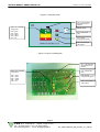
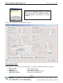
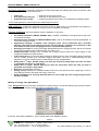
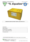
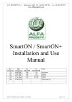
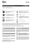
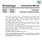
Revision no. 0 dd. 14/04/2008
SERVICE MANUAL SMART ENERGY CB
“SMART ENERGY CB”
SERVICE MANUAL
P.B.M. S.r.l. via Barella, Z.I. - VIGNOLA ( MO ) ITALIA
Tel. + 39 (059) 7705311 - Fax + 39 (059) 7705300
http://www.gruppopbm.it e-mail : [email protected]
file : SMART ENERGY CB_manuale_V1.0_GB.doc
Revision no. 0 dd. 14/04/2008
SERVICE MANUAL SMART ENERGY CB
CONTENTS
CHAPTER 1: FOREWORD.......................................................................................................................................3
CHAPTER 2: DESCRIPTION OF THE AP877 CONTROL CARD ..........................................................................4
CHAPTER 3: PROGRAMMING THE SMARTIC CONNECTOR.............................................................................7
CHAPTER 4: OPERATION....................................................................................................................................11
CHAPTER 5: DESCRIPTION OF THE Wa-CHARGING CHARACTERISTIC ......................................................12
CHAPTER 6: DESCRIPTION OF THE W0Wa-CHARGING CHARACTERISTIC .................................................13
CHAPTER 7: LIST OF LED INDICATIONS ...........................................................................................................14
CHAPTER 8: INSTALLATION, SAFETY, FAILURE DETECTION, AND MAINTENANCE..................................15
WIRING DIAGRAMS...............................................................................................................................................20
Smart Energy CB Wa single-phase .................................................................................................................20
Smart Energy CB Wa three-phase...................................................................................................................21
Smart Energy CB WOWa three-phase ............................................................................................................22
page 2
P.B.M. S.r.l. via Barella, Z.I. - VIGNOLA ( MO ) ITALIA
Tel. + 39 (059) 7705311 - Fax + 39 (059) 7705300
http://www.gruppopbm.it e-mail : [email protected]
file : SMART ENERGY CB_manuale_V1.0_GB.doc
Revision no. 0 dd. 14/04/2008
SERVICE MANUAL SMART ENERGY CB
CHAPTER 1: FOREWORD
SMART ENERGY CB battery chargers are controlled by the AP877 electronic card which interfaces with the
SMARTIC II connector installed on battery through an RS485 communication bus.
Communication takes place through 2 signals connected to the auxiliary contacts of the battery charger plug,
which connecting battery to battery charger interconnect with the corresponding contacts on the battery-side
connector, reaching from there SMARTIC II.
Any action performed by the AP877 card, and therefore by the battery charger, is controlled by the SMARTIC II
connector. Measured values (like the presence of mains voltage), or any events detected by the AP877 card, are
communicated to the SMARTIC II. It uses this info together with the info checked directly, like battery voltage,
current, Ah in the battery, to manage the operation of the battery charger.
The charging system is therefore configured as shown in the picture below:
Battery
SMART ENERGY CB
SMARTIC II
Battery connector with
auxiliary contacts for
communication with the
battery charger
Battery
charger
connector with auxiliary
contacts
for
communication
with
SMARTIC II
Below you will find basic information concerning SMARTIC II and the programming of charge parameters on it.
For complete information on the operation of the SMARTIC II connector, its programming modes, possibility
to set times for starting the charging process when energy is cheaper, refer to the user manual of the SMARTIC
II device enclosed.
The AP877 card controls SMART ENERGY battery chargers, both single and three-phase. This card is
suitable for chargers charging batteries with different capacities and voltages from 12 to 96V and with Wa or
W0Wa charging characteristics.
page 3
P.B.M. S.r.l. via Barella, Z.I. - VIGNOLA ( MO ) ITALIA
Tel. + 39 (059) 7705311 - Fax + 39 (059) 7705300
http://www.gruppopbm.it e-mail : [email protected]
file : SMART ENERGY CB_manuale_V1.0_GB.doc
Revision no. 0 dd. 14/04/2008
SERVICE MANUAL SMART ENERGY CB
CHAPTER 2: DESCRIPTION OF THE AP877 CONTROL CARD
Pictures below show the layout of the main components both on components and welding sides.
Figure 2.1: layout of components side of the AP877 card
J4: pins nos. 4, 3, 2, 1
F1: fuse for
power supply
card
J5: pins nos. 3, 2, 1
J6: pins nos.
8, 7, 6, 5, 4, 3, 2, 1
P1:
pushbutton
RL2
SW1
ON/OFF
RL3
RL1
page 4
P.B.M. S.r.l. via Barella, Z.I. - VIGNOLA ( MO ) ITALIA
Tel. + 39 (059) 7705311 - Fax + 39 (059) 7705300
http://www.gruppopbm.it e-mail : [email protected]
file : SMART ENERGY CB_manuale_V1.0_GB.doc
Revision no. 0 dd. 14/04/2008
SERVICE MANUAL SMART ENERGY CB
Figure 2.2: adhesive panel
LD4 = LED indicating
the electrolyte level
ON/OFF
LED’s bar indicating
charge level:
ON/OFF button
LB5 = green
LB4 = green
LB3 = yellow
LB2 = yellow
LB1 = red
LD1 = Failure LED
(red)
LD2 = End of
charging LED (green)
LD3 = Final Charge
LED (yellow)
Figure 2.3: layout of welding site
LD4 = LED indicating
the electrolyte level
ON/OFF
LED’s bar indicating
charge level:
LD1 = Failure LED
(red)
LB5 = green
LB4 = green
LB3 = yellow
LB2 = yellow
LB1 = red
LD2 = End of
charging LED (green)
LD3 = Final Charge
LED (yellow)
page 5
P.B.M. S.r.l. via Barella, Z.I. - VIGNOLA ( MO ) ITALIA
Tel. + 39 (059) 7705311 - Fax + 39 (059) 7705300
http://www.gruppopbm.it e-mail : [email protected]
file : SMART ENERGY CB_manuale_V1.0_GB.doc
Revision no. 0 dd. 14/04/2008
SERVICE MANUAL SMART ENERGY CB
Below you will find a description of components shown in the figures above.
J4 connector
PIN
1
2
3
4
Location on
Location
battery
charger battery
connector
connector
Description
5V
GND
B
A
Function
Not connected
Not connected
RS485-B line
RS485-A line
right
left
on Colour on the
CV876 cable
left
right
White or yellow
Brown or green
Connector L5
PIN
Description
Function
1
B + = Battery +
Power supply positive input
2
B - = Battery Power supply negative input
3
AC = mains presence
Sensing mains presence
Faston J6
PIN
Description
1
1st stage (W0)
2
2nd stage
(Wa)
3
4
5
6
7
ON
24V AC
OFF
AUX-NA
AUX-COM
8
AUX-NC
Connector P1
PIN
Description
1
Push-button
2
Push-button
DIP SWITCH SW1
PIN
Description
1
Not used
2
Not used
3
Not used
4
Not used
Function
Line of 1st stage contactor (WO) if the battery charger is
WOWa
Line of 2nd stage contactor (Wa) if the battery charger is
WOWA
Reference
RL3.NC
ON/OFF contactor line if the battery charger is Wa
Contactor power supply 24V AC
NC contact of ON/OFF relay
NO contact - auxiliary relay (enabled at charge end)
Common contact – auxiliary relay (enabled at charge
end)
NC contact of the auxiliary relay (enabled at charge end)
RL3.C = RL1.NO
RL1.C
RL1.NC
RL2.NO
RL2.C
RL3.NO
RL2.NC
Function
ON/OFF push-button – pin 1
ON/OFF push-button – pin 2
Function
Not used
Not used
Not used
Not used
page 6
P.B.M. S.r.l. via Barella, Z.I. - VIGNOLA ( MO ) ITALIA
Tel. + 39 (059) 7705311 - Fax + 39 (059) 7705300
http://www.gruppopbm.it e-mail : [email protected]
file : SMART ENERGY CB_manuale_V1.0_GB.doc
Revision no. 0 dd. 14/04/2008
SERVICE MANUAL SMART ENERGY CB
CHAPTER 3: PROGRAMMING THE SMARTIC CONNECTOR
Below you will see how rated data of batteries and chargers can be programmed on the SMARTIC II connector.
You will also find an introduction to basic parameters to be entered for the proper operation of the SMART
ENERGY CB battery charger.
Programming can be performed from a PC through the AP160UIR USB cable and the SMARTVIEW II software
or, in the case of SMARTIC II GPRS, from the WEB site www.alfaprogetti.com, entering from there the SMART
SERVICE area.
Below you will find a description of the programming through SMARTVIEW II.
To perform the programming you need to:
1) Have a AP160UIR cable
2) Install the driver for the USB cable /IR AP160UIR (driver for Operating systems Windows 2000, XP e
Vista)
3) Install the SMARTVIEW II software, available at the WEB site www.alfaprogetti.com in the download
area, on your PC.
And perform following steps:
-
Connect the AP160UIR adapter to an USB port
Connect the AP160UIR to the IR connector of SMARTIC II
Execute the SmartView II program
Press the password key and enter a password (PWD) with level 2, enabled to the programming of
parameters on SMARTIC II
Note:
The SmartView II program has 3 different access levels available:
• Level 0 password:
Lowest password level
The user is authorized only to consult data
• Level 1 password:
Middle password level
Previous level functions and data download onto PC
• Level 2 password:
Highest password level
Previous level functions and data writing onto SMARTIC II connector
The authorization level associated with the entered PWD is shown on the status bar of the application
package (below SW window)
ON LINE mode
OFF LINE mode
Connection
centralized
inside the
network
to
the
database
company
Disconnection from the
centralized
database
Password entry
page 7
P.B.M. S.r.l. via Barella, Z.I. - VIGNOLA ( MO ) ITALIA
Tel. + 39 (059) 7705311 - Fax + 39 (059) 7705300
http://www.gruppopbm.it e-mail : [email protected]
file : SMART ENERGY CB_manuale_V1.0_GB.doc
Revision no. 0 dd. 14/04/2008
SERVICE MANUAL SMART ENERGY CB
By pressing the CONNECT SMARTIC key, serial
ports of the PC are tested looking for a SMARTIC
connector connected. In the example to the left, a
connected SMARTIC was detected on the COM2
serial port.
Click on a tab on page top to select programming page:
Battery rated parameters:
Rated parameters of the battery on which a SMARTIC II connector is installed and size of current sensor:
•
•
•
•
Battery Voltage
Battery Ah
Charging current
Rated sensor current
= rated voltage of battery
= rated capacity of battery
= rated current of the battery charger
= current size of the Hall Sensor
page 8
P.B.M. S.r.l. via Barella, Z.I. - VIGNOLA ( MO ) ITALIA
Tel. + 39 (059) 7705311 - Fax + 39 (059) 7705300
http://www.gruppopbm.it e-mail : [email protected]
file : SMART ENERGY CB_manuale_V1.0_GB.doc
Revision no. 0 dd. 14/04/2008
SERVICE MANUAL SMART ENERGY CB
Discharge parameters: parameters controlling the discharge stage and enabling the forks lock function under
special working conditions of the forklift truck.
•
•
•
Forks lock
Anti opportunity charging
Underdischarge voltage
= Selection of forks lock function
= Selection of anti opportunity function
= Voltage level below which battery is considered as underdischarged
For any other parameter, please refer to the SMARTVIEW II manual.
WEB parameters: configuration parameters providing access to WEB service. The parameters only depend on
the contract you made with your telephone company (only for S2GPRS connectors).
Charging parameters: show the operation mode of SMARTIC II connector.
•
•
•
•
•
•
•
•
•
•
•
Ah-method (enabled for SMART ENERGY CB): if enabled, it disables the charging method with timecontrolled final charge.
SmartCB Control (enabled for SMART ENERGY CB): it has to be enabled for allowing SMARTIC to
control the charging process
Opportunity Charging: if enabled, short charging cycles can be performed with a possible
advance interruption of the charging process with no indication of failures and collection of data
from different consecutive charging processes (used with AGV systems)
Recharging increase %: energy percentage dissipated during the charging process, that is Ah increase
percentage compared to the Ah discharged in the same cycle.
Voltage threshold: Gassing Point: it makes the charging process switch from initial charge to final
charge and enables the relevant timers.
Final charge time: time measured after reaching the gassing point in time controlled charging processes
and for a safety timeout in Ah controlled charging processes. This time is measured during the first
alignment cycle to set a starting point corresponding to a fully charged battery.
Safety timer 1st stage: Should voltage not reach the threshold voltage within this time, an alarm
is generated and charge is interrupted.
Safety timer 2nd stage: Should capacity not reach the rated value within this time, an alarm is
generated and charge is interrupted.
Autostart: Autostart delay selection.
Energy saving: Enabling of a scheduler where times have to be entered for each single day in order to
let charging processes start when the energy cost is low.
Setup: Pushbutton for selecting Autostart times for each single day if the energy saving function
has been enabled.
Writing of energy save parameters
If the “Energy Saving” entry has been selected in the charge section, the relevant Setup mask can be accessed.
Once data have been changed, press the OK key to close the mask.
Press the “Send data to SMARTIC ” key to transfer data to the SMARTIC device.
page 9
P.B.M. S.r.l. via Barella, Z.I. - VIGNOLA ( MO ) ITALIA
Tel. + 39 (059) 7705311 - Fax + 39 (059) 7705300
http://www.gruppopbm.it e-mail : [email protected]
file : SMART ENERGY CB_manuale_V1.0_GB.doc
Revision no. 0 dd. 14/04/2008
SERVICE MANUAL SMART ENERGY CB
Example: if you want to set the timeband 20:00 Æ 6:00 for weekdays and 0:00 Æ 23:59 (the whole day)
for Saturdays and Sundays, you need to set it as follows:
20:00
06:00
20:00
06:00
20:00
06:00
20:00
06:00
20:00
06:00
00:00
23:59
00:00
23:59
Once data have been entered in the scheduler, press the OK key to exit from it.
Once configuration parameters have been entered, press the “SEND DATA TO SMARTIC ” key and “SET
CLOCK” key.
page 10
P.B.M. S.r.l. via Barella, Z.I. - VIGNOLA ( MO ) ITALIA
Tel. + 39 (059) 7705311 - Fax + 39 (059) 7705300
http://www.gruppopbm.it e-mail : [email protected]
file : SMART ENERGY CB_manuale_V1.0_GB.doc
Revision no. 0 dd. 14/04/2008
SERVICE MANUAL SMART ENERGY CB
CHAPTER 4: OPERATION
•
•
•
•
•
•
•
•
On connecting Smart Energy to battery by means of a SMARTIC II connector, communication between
the 2 devices begins. This is indicated by a green blinking LED, located next to the circular connector, which
the communication cable is connected to, on SMARTIC II. This is also indicated by the battery charger
performing an Autotest, where all LED’s light up in sequence. Afterwards only will the LB1…LB5 LED’s
remain lit, depending on the charge state of the battery. When Smart Energy is connected to battery for the
first time, the red LB1 LED will blink, which indicates that battery is empty.
The red FAULT LED will blink after the Autotest, if connection to mains is not performed.
Once connection to mains has been performed, the charging process starts as indicated by the LB1,
LB2…LB5 LED’s, which will light up in sequence from the bottom to the top.
After a certain amount of time, depending on the initial discharge state, battery will reach the gassing
threshold and final charge will begin, as indicated by the yellow LD3 LED lighting up.
On charge completion, the green L2 LED, indicating end of charging, will light up.
The charging process can be stopped anytime by pressing the ON-OFF button on the battery charger.
Charge interruption will be indicated by a failure to light up in sequence of the LED’s (LB1 …LB5). Pressing
the button again, the charging process is restarted and the LB1…LB5 LED’s will light up in sequence from
the bottom to the top.
All LED indications described above correspond to identical indications given by homologous LED’s on the
SMARTIC II connector.
For further information on operation, programming modes, possibility of setting times of the SMART.IC®
connector in order to charge batteries taking advantage of low-cost energy, please refer to the User Manual
of the SMART.ICII® device.
page 11
P.B.M. S.r.l. via Barella, Z.I. - VIGNOLA ( MO ) ITALIA
Tel. + 39 (059) 7705311 - Fax + 39 (059) 7705300
http://www.gruppopbm.it e-mail : [email protected]
file : SMART ENERGY CB_manuale_V1.0_GB.doc
Revision no. 0 dd. 14/04/2008
SERVICE MANUAL SMART ENERGY CB
CHAPTER 5: DESCRIPTION OF THE Wa-CHARGING CHARACTERISTIC
Figure 5.1: Description of the Wa charging characteristics
I
V
100%
2.70 V/cell
50%
2.40 V/cell
25%
2.00 V/cell
INITIAL CHARGE
FINAL CHARGE
PAUSE
EQUALIZING
time
The charging characteristic shown above is made up of the following stages:
• Initial charge with decreasing current until the set gassing point is reached. Should this stage last longer than
10 hours (settable time), the charging process is stopped and a fault is signalled (safety time exceeded
during stage 1).
• Final charge: it is performed in different ways depending on the status of the Ah control.
If it is enabled the final charge is performed following a special algorithm, thanks to which it is possible to
determine how many Ampere-hours have to be reinstated into the battery. If the charging time exceeds 6
hours (settable time), the charging process is stopped and a fault is signalled (safety time exceeded during
stage 2).
In a time controlled charge, the charging process is stopped after a set time (standard setting: 3h).
The first charge after disconnection of SMARTIC II from power supply is time controlled.
● Pause: waiting for battery cooling down ((6 hours long).
● Equalizing charge: Equalizing is made up of a certain amount of pulse packages, each of which consists of
charges (T.ON=5 min.) and pauses (T. OFF=55min.). Goes on, until battery is disconnected from
battery charger.
page 12
P.B.M. S.r.l. via Barella, Z.I. - VIGNOLA ( MO ) ITALIA
Tel. + 39 (059) 7705311 - Fax + 39 (059) 7705300
http://www.gruppopbm.it e-mail : [email protected]
file : SMART ENERGY CB_manuale_V1.0_GB.doc
Revision no. 0 dd. 14/04/2008
SERVICE MANUAL SMART ENERGY CB
CHAPTER 6: DESCRIPTION OF THE W0Wa-CHARGING CHARACTERISTIC
I
100%
V
Figure 6.1: Description of the Wa charging characteristics
2.70 V/cell
75%
2.40 V/cell
50%
25%
2.00 V/cell
INITIAL CHARGE
FINAL CHARGE
PAUSE
EQUALIZING
time
The charging characteristic shown above is made up of the following stages:
• Initial charge with a higher current (equal to 1/5 of the battery capacity) for a faster charging process. This is
obtained by connecting the mains voltage to a primary winding with fewer turns, thus obtaining a higher output
current on the secondary winding.
Should this stage last longer than 10 hours (settable time), the charging process is stopped and a fault is
signalled (safety time exceeded during stage 1). If the charge has been programmed in Ah and the capacity
in the battery exceeds the rated value by 10%, the charge stops and a failure is signalled (safety
amperehours exceeded).
Final charge begins on reaching the threshold set by means of the JA1-JA7 jumpers and adjusted, if needed,
by means of the P1 trimmer.
• Final charge: at the beginning of the final charge the mains voltage is disconnected from the primary winding
of the WO transformer, then it is connected to the Wa primary winding which allows the charging current to be
reduced by 20% compared to the rated current.
It is performed in different ways depending on the status of the Ah control.
If it is enabled the final charge is performed following a special algorithm, thanks to which it is possible to
determine how many Ampere-hours have to be reinstated into the battery. If the charging time exceeds 6
hours (adjustable time), the charging process is stopped and a fault is signalled (safety time exceeded
during stage 2).
In a time controlled charge, the charging process is stopped after a set time (standard setting: 3h).
The first charge after disconnection of the SMARTIC II connector from power supply, is time controlled.
● Pause: waiting for battery cooling down ((6 hours long)
● Equalizing charge
Equalizing is made up of a certain amount of pulse packages, each of which consists of charges (T.ON=5
min.) and pauses (T. OFF=55min.). Goes on, until battery is disconnected from battery charger.
page 13
P.B.M. S.r.l. via Barella, Z.I. - VIGNOLA ( MO ) ITALIA
Tel. + 39 (059) 7705311 - Fax + 39 (059) 7705300
http://www.gruppopbm.it e-mail : [email protected]
file : SMART ENERGY CB_manuale_V1.0_GB.doc
Revision no. 0 dd. 14/04/2008
SERVICE MANUAL SMART ENERGY CB
CHAPTER 7: LIST OF LED INDICATIONS
LD4 = LED indicating
electrolyte
level
ON/OFF
LED’s bar indicating
charge level:
ON/OFF butt
LB5 = green
LB4 = green
LB3 = yellow
LB2 = yellow
LB1 = red
LD1 = Failure LED
(red)
LD2
=
End
of
charging LED (green)
LD3 = Final charge
LED (yellow)
The table below show indications given through LED’s.
Table 7.1: Description of LED’s indications
LED indications
Only mains power supply
Only battery power supply with empty
battery (first switch on)
Autostart
Initial charge
Final charge
End of charging
Pause during equalizing or floating
charge
Charge during equalizing or floating
charge
Mains failure
Communication failure with SMARTIC II
Overload cutout failure*
Safety timer fault, 1st stage
Safety Ah fault, 1st stage:
110% battery charge during 1st stage
Safety timer fault 2nd stage with Ah control
Electrolyte control not programmed
Electrolyte control programmed and level
above threshold (standard value 128)
Electrolyte control programmed and level
below threshold (standard value 128)
Legend:
OFF
ON
BLK
BLV
BLF
*
SCORR
LD1
RED
LD2
GREEN
LD3
YELLOW
LB1,LB2,LB3,
LB4,LB5
OFF
-
LD4
GREEN/
RED
OFF
-
OFF
BLK
OFF
-
BLK
OFF
OFF
OFF
BLK
BLK
OFF
OFF
ON
-
BLK
OFF
ON
ON
-
-
SCORR.
SCORR.
ON
-
BLF
OFF
OFF
OFF
OFF
BLK
ON
ON
ON
-
-
-
OFF
-
-
-
-
GREEN
RED
GREEN
-
-
-
-
RED
-
OFF
LB1 BLV
= LED is OFF
= LED is constant
= LED is blinking slowly (T = 1 sec)
= LED is blinking quickly (T = 0.2 sec)
= LED flashes (for 0.2 sec) every 2 seconds
= refer to Chapter no. 8 as for faults
= LED can be in different conditions
= lights up from the bottom to the top ( = during the charge)
page 14
P.B.M. S.r.l. via Barella, Z.I. - VIGNOLA ( MO ) ITALIA
Tel. + 39 (059) 7705311 - Fax + 39 (059) 7705300
http://www.gruppopbm.it e-mail : [email protected]
file : SMART ENERGY CB_manuale_V1.0_GB.doc
Revision no. 0 dd. 14/04/2008
SERVICE MANUAL SMART ENERGY CB
CHAPTER 8: INSTALLATION, SAFETY, FAILURE DETECTION, AND MAINTENANCE
In this chapter the main info are provided, necessary to the Service Personnel to carry out a correct installation
of the battery charger, a quick detection of the most common failures, and a proper maintenance of the unit.
8.1.
INSTALLATION
The general notes on installation are already provided in the user manual enclosed to each battery charger.
Below only the basic info are summarized.
• It is essential to connect the charger to a mains supply of standards corresponding to the power of the
battery charger installed to be sure that the charger functions properly.
• The charger is equipped with taps to adjust the charger to mains, compensating for possible differences
between the voltage available at the user’s site and the rated voltage.
• Single-phase chargers are preset for a rated voltage of 230V AC.
• Three-phase chargers are preset for a rated voltage of 400V AC.
• Checking the mains voltage is essential: a mains voltage which is too high or too low compared to the
rated value, may result in a big different current delivered by the battery charger with following malfunctions
of the charger and lower performances of the battery.
8.2.
SAFETY NOTES
1) Ensure that the battery charger is positioned onto a solid and flat and even floor, and is protected against
possible impacts from forklift trucks and other vehicles.
2) The battery charger has to be installed in a site free from materials which may prevent its natural ventilation,
necessary to dissipate the produced heat.
3) Do not position the charger near explosive, inflammable, and/or dangerous materials.
4) Make sure that the battery charger is neither exposed to rain, moisture or fog, nor splashed with water. Do
not install it outdoor*, under unstable sheds or shelters.
* with the exception of special versions with protection class IPX3 or higher.
5) Check condition of sockets, fuses and/or switches present at user’s site and of connection cables. Do not
use additional cables to prolong the existing power cord!!
6) Make sure that battery charger is equipped with an electrical connector suitable for its power and current and
is connected to an adequate mains socket!! (check inputs and power on the rating plate).
7) Check connections between battery and charger: if they are damaged and/or worn-out they may produce
dangerous overheatings.
8) All checks and/or settings have to be performed by qualified, skilled, and authorised personnel only.
8.3 FAILURE DETECTION
Below you will find only general information. Since different kinds of failures and/or malfunctions may occur,
please refer to experienced Service Technicians for any problem.
As for the battery chargers in question, the following is true:
Wa- or WOWa-chargers with decreasing currents may also show seeming malfunctions due to external
causes, such as electrical systems and/or batteries in bad conditions. Take this into account when
checking them.
8.3.1.
NECESSARY INSTRUMENTS
- Handheld multifunctional digital tester
- DC clamp meter
8.3.2. FIRST CHECKS TO BE PERFORMED
•
•
•
•
Preliminary check on the general conditions of battery charger and battery (see previous paragraph).
Make sure that the power cord of the charger is properly connected to the mains socket and that the mains
switch is OFF.
Check the mains power supply inside the battery charger.
Make sure that charger has been properly connected to battery and check the condition of connectors.
page 15
P.B.M. S.r.l. via Barella, Z.I. - VIGNOLA ( MO ) ITALIA
Tel. + 39 (059) 7705311 - Fax + 39 (059) 7705300
http://www.gruppopbm.it e-mail : [email protected]
file : SMART ENERGY CB_manuale_V1.0_GB.doc
Revision no. 0 dd. 14/04/2008
SERVICE MANUAL SMART ENERGY CB
8.3.3.
FAILURE DETECTION AND MEASURES
FAILURE
POSSIBLE CAUSES
REMEDIES AND/OR CHECKS TO BE PERFORMED
1) Check the protection fuse on DC output (battery side).
2) Check the fuse on the AP877 card.
BATTERY IS
CONNECTED BUT THE
CARD DOES NOT
SIGNAL IT (CHARGER
OFF)
3)
- Blown fuses
- Defective connections
and/or contacts
4)
- Defective card
Check charging cables path making sure that there are
neither bad contacts on plugs nor overheatings on
cable segments or terminals.
Make sure that the digital tester detects battery voltage
presence on the card connector (follow the relevant
wiring diagram).
5) Check and, if needed, replace the AP877 control card.
BATTERY
IS
1) Check charging cables path making sure that there are
CONNECTED BUT THE
neither bad contacts on plugs nor overheatings on
- Defective connections
CHARGER DOES NOT
cable segments or terminals.
and/or contacts
START THE CHARGE
2) Check and, if needed, replace the AP877 control card.
- Defective card
AND THE CARD SIGNALS
- Defective SMARTIC II 3) Check if the green LED on SMARTIC II blinks (LED on
A SERIAL ERROR (red
AP876 card, next to serial connector).
flash)
1) Check the phase voltage output from the contactor
contacts and phase voltage input to main Transformer
BATTERY AND MAINS - Power failure
(TR).
ARE CONNECTED, THE - Blown fuses
CONTACTOR OR RELAY - Defective connections 2) Check that cables are in good conditions and there are
CLOSES
BUT
THE and/or contacts
no defective cables and/or terminals.
CHARGER DOES NOT Defective
rectifier
3) Check the output fuse on battery side (F2)
DELIVER ANY CURRENT
bridge
4) Check the efficiency of the rectifier bridge* (RD).
1) Battery already charged or not completely discharged.
- Power failure
2) Failure of one or more mains phases; check the mains
- Blown fuses
fuses and the contacts of the contactor (TL).
- Defective connections
3) Check that the pin for adjustment to mains (CM) is in
THE
BATTERY and/or contacts
the correct position as to the mains present.
CHARGER
DELIVERS Defective
rectifier
LITTLE CURRENT
bridge
4) Check the integrity of cables making sure that there are
- Low mains voltage
no burnt wires or oxidized terminals in the power circuit
- Wrong wiring of the
up to the charging cables.
Main Transformer
5) Check the condition of the rectifier bridge* (RD).
1) Make sure that the charger has a power suitable for the
battery to be recharged.
THE
DELIVERS
CURRENT
2) Check that the pin for adjustment to mains (CM) is in
- Mains very high
the correct position as to voltage available.
CHARGER - Adjustments not correct
3) Check that battery does not have too long and/or too
TOO MUCH - Battery too low
strong discharges compared to its own capacity.
- Wrong wiring of the
Main Transformer
4) Check mains voltage.
5) Check the proper connection of the Input Voltage on
the input connector of Transformer.
page 16
P.B.M. S.r.l. via Barella, Z.I. - VIGNOLA ( MO ) ITALIA
Tel. + 39 (059) 7705311 - Fax + 39 (059) 7705300
http://www.gruppopbm.it e-mail : [email protected]
file : SMART ENERGY CB_manuale_V1.0_GB.doc
Revision no. 0 dd. 14/04/2008
SERVICE MANUAL SMART ENERGY CB
FAILURE
POSSIBLE CAUSES
REMEDIES AND/OR CHECKS TO BE PERFORMED
1) Make sure that the power (kW) available at customer’s
site is corresponding to that needed by the charger.
2) Check the auxiliary transformer (TA) for good working
order.
3) Check the TL contactor coil, making sure that there are
neither burnings nor short-circuits.
4) Check the Main Transformer (TR), making sure that
there are neither short-circuited nor burnt windings.
ONE OR MORE MAINS
5) Make sure that the rectifier bridge* (RD) has not short- Little power available
FUSES BURN, OR THE
circuited.
Short-circuited
CUT-OUT SWITCH ON
6) Check that charger does not deliver too much current
components
THE PANEL OPERATES
(see the above-mentioned information).
7) If the cut-out-switch on the panel operates after a few
minutes, check the switch installed since the charger is
a particularly heavy load from an electrical point of
view.
It is suggested to use automatic and/or differential cutouts as protections of battery chargers with operation
characteristics suitable for the specific load (K and D
curves).
BURNT FUSE ON CARD
- Defective card or wrong 1) Make sure that the power supply of the card is lower
than 144V.
power supply of the
card.
2) Replace the AP877 card.
1) Check that polarity of the output cables and on battery
connector is correct (polarity reversal may occur when
maintenance is performed and/or cables and/or battery
connectors are replaced).
- Polarity reversal
BURNT OUTPUT FUSE
- Defective and/or short2) Check that battery charger does not deliver too much
ON BATTERY SIDE
circuited components
current (see the above-mentioned information).
3) Make sure that the rectifier bridge* (RD) is not shortcircuited.
1) Check that SMARTIC II has been programmed
correctly related to connected battery (battery voltage,
THE CHARGER DOES - Card setting not correct
capacity, etc.).
- Battery not in good
NOT STOP
2) Press the ON/OFF key on the battery charger and
AT
THE
END
OF condition
check the ON/OFF relay for proper operation.
CHARGING
- Defective card
THE
CHARGER
DETECTS AND SIGNALS - Overall check
AN "ALARM" CONDITION
1) Check mains voltage and working order of the battery
charger.
2) Check working order of battery, cell by cell, making
sure that there are no short-circuited or low-voltage
cells.
3) Check SMARTIC II for proper programming.
page 17
P.B.M. S.r.l. via Barella, Z.I. - VIGNOLA ( MO ) ITALIA
Tel. + 39 (059) 7705311 - Fax + 39 (059) 7705300
http://www.gruppopbm.it e-mail : [email protected]
file : SMART ENERGY CB_manuale_V1.0_GB.doc
Revision no. 0 dd. 14/04/2008
SERVICE MANUAL SMART ENERGY CB
( * ) Checking
the rectifier bridge (RD)
The rectifier bridge is made up of auto diodes on aluminium sheets which act as dissipaters.
To achieve different current capacities, the bridge is made up of a variable number of diodes, positioned in
parallel on the same plate.
To test operation of the Bridge, disconnect it from the charger.
Some diodes have the anode (positive pole) on the phase inputs and the cathode (negative pole) connected to
the output positive pole of the bridge (corresponding to the negative pole of the battery).
To check the condition of these diodes, use a Digital tester in “Check-Diode” mode and make sure that a diode
voltage (0.4V – 1V) is present by pointing the positive test prod on the Phases and the negative test prod on the
output positive pole. Make sure that there is an infinite diode voltage between the output positive pole and each
mains input.
The other diodes have the cathode (negative pole) on the phase inputs and the anode (positive pole) connected
to the output negative pole of the Bridge (corresponding to the battery negative pole).
To check the condition of these diodes, use a Digital tester in “Check-Diode” mode and make sure that a diode
voltage (0.4V – 1V) is present by pointing the positive test prod on the Phases and the negative test prod on the
output positive pole. Make sure that there is an infinite diode voltage between the positive output pole and each
mains input.
In addition to these instrumental checks, the following empirical checks can be performed:
• Visual checks to exclude that there are blown diodes or an unsoldered rheophore.
• If strong vibrations are heard during the charging process and the charging process is not performed
regularly because the cut-out-switch or the fuses operate, it means that the bridge is in short-circuit and
needs replacing.
• On the other hand it is easy to diagnose the open bridge failure on a three-phase charger by operating the
charger without connecting the battery and forcing the power supply of the transformer. If an anomalous
transformer voltage, instead of a no-load voltage, is detected under these conditions, it means that the
rectifier bridge is at least partially open and needs replacing.
• The no-load output voltage of chargers corresponds to the values contained in the following table (provided
that transformer is correctly powered).
RATED BATTERY
VOLTAGE
12V
24V
36V
40V
48V
72V
80V
96V
NO-LOAD OUTPUT VOLTAGE (DC)
FOR 1-PHASE BATTERY CHARGERS
14 ÷ 15V
28 ÷ 30V
42 ÷ 44V
46 ÷ 48V
56 ÷ 58V
85 ÷ 87V
95 ÷ 98V
112 ÷ 115V
NO-LOAD OUTPUT VOLTAGE (DC)
FOR 3-PHASE BATTERY CHARGERS
18 ÷ 24V
33 ÷ 38V
50 ÷ 58V
60 ÷ 70V
72 ÷ 80V
100 ÷ 108V
110 ÷ 120V
130 ÷ 150V
page 18
P.B.M. S.r.l. via Barella, Z.I. - VIGNOLA ( MO ) ITALIA
Tel. + 39 (059) 7705311 - Fax + 39 (059) 7705300
http://www.gruppopbm.it e-mail : [email protected]
file : SMART ENERGY CB_manuale_V1.0_GB.doc
Revision no. 0 dd. 14/04/2008
SERVICE MANUAL SMART ENERGY CB
8.3.4.
MAINTENANCE AND CLEANING
All maintenance and cleaning actions have to be performed by qualified, skilled, and authorised
personnel.
•
•
•
•
The battery charger is an electrical device with no moving mechanical parts, therefore it does not need any
special maintenance.
It is however suggested to check, inspect, and clean the charger at least once a year if it operates in a fairly
“clean” environment.
In “hard” conditions, that is in dusty and wet environments, checks have to be performed more frequently.
The main checks to be performed are the following:
− Place the charger/s outdoor and remove the closing panel.
− Wear a faceplate and protection devices. Using compressed air, remove dust accumulated inside the
charger.
− Use non-corrosive detergents to remove sludge deposits or other dirt.
Once the charger has been cleaned, perform the following actions:
− Check the general condition of components and their integrity.
− Replace oxidized cables and/or terminals, if any.
− Use proper sprays to clean electrical contacts on contactors, switches, and selector switches.
− Check the tightening of screws and bolts, replace rusted parts, if any.
− Perform a “dry cleaning” or use proper sprays to clean electronic cards.
− Check the status of both control and power connectors. Check the “wear” of power connectors on
battery and replace them, if necessary.
− Check the condition of electrical plugs.
Once all the above-mentioned actions have been taken, close panels, doors and covers again, and place the
charger/s in its/their position/s again.
page 19
P.B.M. S.r.l. via Barella, Z.I. - VIGNOLA ( MO ) ITALIA
Tel. + 39 (059) 7705311 - Fax + 39 (059) 7705300
http://www.gruppopbm.it e-mail : [email protected]
file : SMART ENERGY CB_manuale_V1.0_GB.doc
Revision no. 0 dd. 14/04/2008
SERVICE MANUAL SMART ENERGY CB
WIRING DIAGRAMS
Smart Energy CB Wa single-phase
page 20
P.B.M. S.r.l. via Barella, Z.I. - VIGNOLA ( MO ) ITALIA
Tel. + 39 (059) 7705311 - Fax + 39 (059) 7705300
http://www.gruppopbm.it e-mail : [email protected]
file : SMART ENERGY CB_manuale_V1.0_GB.doc
Revision no. 0 dd. 14/04/2008
SERVICE MANUAL SMART ENERGY CB
Smart Energy CB Wa three-phase
page 21
P.B.M. S.r.l. via Barella, Z.I. - VIGNOLA ( MO ) ITALIA
Tel. + 39 (059) 7705311 - Fax + 39 (059) 7705300
http://www.gruppopbm.it e-mail : [email protected]
file : SMART ENERGY CB_manuale_V1.0_GB.doc
Revision no. 0 dd. 14/04/2008
SERVICE MANUAL SMART ENERGY CB
Smart Energy CB WOWa three-phase
page 22
P.B.M. S.r.l. via Barella, Z.I. - VIGNOLA ( MO ) ITALIA
Tel. + 39 (059) 7705311 - Fax + 39 (059) 7705300
http://www.gruppopbm.it e-mail : [email protected]
file : SMART ENERGY CB_manuale_V1.0_GB.doc