1
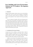
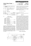
DOUBLE LOCKSTITCH HIGH-SPEED SEAMER
WITH DIRECT DRIVE
WITH BOTTOM AND NEEDLE FEED
SETUP, INSTRUCTION- & SERVICE MANUAL
GC6760
SERIES
2
TYPICAL GC6760 Series
3
TYPICAL GC6760 Series
Thank you for purchasing a TYPICAL sewing machine.
Please read the safety instructions carefully before you
start the machine.
With industrial machines you normally work directly in front
of the moving parts like the needle or the take-up-lever.
A risk of injury can occur from this parts. So make sure that
you are familiar with the machine and listen to the orders of
the instructor for a save and correct handling.
The instruction manual must be always available at the
workplace. Every person that works on the machine must be
familiar with the instruction manual. Only authorized persons
may work on the machine.
4
TYPICAL GC6760 Series
CONTENT
1 //
1/1
1/2
1/3
1/4
1/5
2 //
SAFETY
General safety instructions
Important points for the user
Operating and technical staff
Safety symbols
Safety symbols on the machine
5
5
5
5
6
7
TECHNICAL DATA
8
3 //DESCRIPTION OF
THE MAIN PARTS
9
4 //
INSTALLATION
4/1 Location of the machine
4/2
Carry the machine
4/3
Tilting the machine head
4/4
Re-positioning the machine
4/5
Table top drawing
4/6Installation
4/6/1 Controller and connecting rod
4/6/2 Main switch
4/6/3 Oil pan
4/6/4 Rubber pads and knee lever rod
4/6/5 Machine head
4/6/6Sticker
4/6/7 Thread stand
4/6/8 Installing and adjusting the knee lever 4/7Lubrication
4/8
Test run
5 //
10
11
11
11
11
12
13
13
13
13
14
14
15
15
16
17
18
5/1 5/2
5/3
5/4
5/5
5/6
5/7
5/8
SETTING UP
Inserting the needle
Re-moving the bobbin case
Winding the bobbin
Inserting the bobbin
Threading the upper thread
Setting the stitch length
Using the thread wiper
Using the knee lever
19
6 //
SEWING
23
6/1 6/2
6/3
Switching on and back tacking
Setting the stitch density
Sewing the stitch density
19
19
20
21
21
22
22
22
23
24
24
7 //
THREAD TENSION
7/1 Setting the lower thread tension 7/2
Setting the upper thread tension
7/3
Adjusting the foot pressure
7/4Adjusting the thread length at
the needle after thread cutting
8 //
25
25
25
26
26
CLEANING & MAINTENANCE 27
8/1 Daily cleaning and maintenance
8/1/1Cleaning
8/1/2 Checking the gear box oil level
8/1/3 Re-filling the lubrication oil
8/1/4 Checking the oil level
8/1/5 Checking the needle and thread 8/2Lubricating
28
28
29
30
30
31
32
9 //SETTING THE
HOOK LUBRICATION
33
10 // ADJUSTMENTS
34
9/1 Checking and adjusting the lubrication 10/1 Adjusting the safety switch
10/2
Adjusting the take up spring
10/3
Adjusting the thread regulator
10/4
Adjusting the presser foot height
10/5
Adjusting the feed dog height
10/6
Adjusting the feed dog angle
10/7 Pre-adjustment of the needle bar height
10/8
Adjusting the feed lift movement 10/9Adjusting the hook distance,
needle bar raise and needle height
10/10 Adjusting the thread cutter
10/10/1 Pre-adjusting the roller lever
10/10/2 Pre-adjusting the cam
10/10/3 Setting the movable thread catcher
10/10/4 Timing the cam
10/10/5 Setting the thread release
10/10/6 Setting the knife pressure
10/11 Adjusting the foot pedal
10/12 Sewing stretch and high pile material
10/13Adjusting the electric back-tack switch
on the machine head
33
35
36
37
37
38
39
40
41
42
43
43
43
44
45
46
46
47
48
48
11 //ERROR MESSAGES & POSSIBLE
TROUBLE SHOOTING
49
12 // DISPOSAL OF MACHINE
55
5
TYPICAL GC6760 Series
1 // SAFETY
1/1 General Safety Instructions
This manual and the warning symbols on the machine should
ensure the safe use of the machine, so that no accidents and
injuries may occur. Please read this instruction and also the
safety instructions of the motor manufacturer carefully.
The machine may only be set into operation after this instruction manual has been read and the operator has been trained
by authorized personal.
The machine may only be used as specified and with the
appropriate safety devices. General safety instructions must
be applied.
Take note of the danger and safety instructions on the
machine.
The machine must be switched off, or plug pulled when maintenance and other work e.g. changing of needle, sewing foot,
needle plate, feed dog, bobbin or threading is done, also when
leaving the working place.
Daily maintenance work may only be taken out by properly
trained personnel.
Repairs and special maintenance may only be done by technical personnel or specially trained staff.
Only qualified mechanic may take out work on the electrical
equipment.
Works on live parts are not allowed. Conversions or modifications to the machine may only be done with the common
safety measures.
Only original TYPICAL spare parts or parts which are cleared
by TYPICAL are allowed to use when repairing the machine.
The machine can only be used when the whole unit complies
with the EC-Directive.
The connecting cable must be equipped with a country-specific
connecting plug. This must be done by an electrician.
1/2 Notice to the owner
This manual must be at all times be available for the operator
as it is part of the machine. Make sure that the persons whom
are working on the machine read it before starting the machine
for the first time.
The owner must make sure that the machine is in good
working order.
The owner must check that all safety devices are in place and
in working order.
The owner must make sure that only authorize, trained persons
are working on the machine
1/3 Operators and Technical Staff
It is the operator´s responsibility to take care of small
adjustments, operating and cleaning of the machine.
The operator has to refrain from any actions that can
interfere with the safety of the machine. There is no jewelry,
changings or rings to be worn while working on the machine.
The clothing should be tight fitting. Only authorized personnel
is allowed on the workplace. The incidence of an error on the
machine that can interfere with the safety must be reported
to the supervisor.
The skilled technical staff is responsible for lubricating,
maintenance, repairing and adjusting of the machine.
The machine must be switched of before starting any work
on the machine and be secured that it can´t be switched on
by evident. Exceptions are listed in the regulation EN 50110.
The safety guards must be replaced after finishing the repair
and maintenance work.
Operators and technical staff must take attention of the safety
and operating instructions in this manual.
6
TYPICAL GC6760 Series
1 // SAFETY
1/4 Safety Symbols
Caution
When ignoring this sign injury or damage to the machine or
equipment can occur
A triangle always means „“Danger““. The picture inside the
triangle shows the kind of danger that can occur. Injury is
possible when ignored.
This sign indicates that you are not allowed to do something.
This symbol indicates that you have to do something.
In this case to earth the machine.
7
TYPICAL GC6760 Series
1 // SAFETY
1/5 Warning signs on the machine
The following warning signs are on the machine. Please follow
these whenever you use the machine. If they are not readable
or removed please contact your TYPICAL-Dealer.
1
Caution
Moving parts can cause injuries. Please follow the safety
precautions. Push the main switch before you thread the
machine or change the needle, bobbin e.g. or clean the
machine.
A
3
2
1
The machine must be earthed at all times. Otherwise
there is the danger of electrocution. The functioning of the
machine can also be impaired.
B
4
Safety devices
A Finger guard
B Take up lever guard
2
3
↓
Work direction
4
Danger
4
8
TYPICAL GC6760 Series
2 // TECHNICAL DATA
•
•
•
•
•
•
Stitch type 301
Max. sewing speed 4.000 s.p.m. (GC6760 MD3)
Max. stitch length 5,5 mm (GC6760 HD3)
Max. foot lift 16 mm with knee lever
Floating foot fine adjustment for better sewing quality
Adjustable take up lever (58 -62 mm) for better sewing
results on different material
AUTOMATIC CLOSED LUBRICATION SYSTEM
SUBCLASSES
• GC6760MD3
High speed sewing machine for fine to medium thread and
material (needle bar raise 33 mm)
• GC6760HD3
High speed sewing machine for heavy thread and material
(needle bar raise 35 mm)
301
67630-
MD3
•
4,000
•
4.5
HD3
•
3,500
•
5.5
134/DPx5
75-110
134/DPx5
120-140
33
•
6/16
•
•
•
°
M
35
•
6/16
•
•
•
°
H
9
TYPICAL GC6760 Series
3 // NAMES OF THE MAIN PARTS
13
2
14
1
12
11
3
10
4
9
15
5
8
7
6
1//
2//
3//
4//
5//
6//
7//
8//
9//
10//
Bobbin winder
Thread wiper
Lifting lever
Back tack button
Sewing foot
Control circuit
Knee lever
Main switch
Oil sight window
Revers lever
11// Stitch length regulator
12// Hand wheel
13// Tread stand
Safety devices
14// Take up lever guard
15// Finger guard
10
TYPICAL GC6760 Series
4 // INSTALLATION
Caution
Please note that the machine may only be installed by qualified personnel.
Caution
Contact your TYPICAL-Dealer or an electrician when work on the power supply is necessary.
Caution
The weight of the machine is 46 kg. The installation should be taken out by two persons.
Caution
Connect the machine to the electricity when finished installing the machine.
Injury may occur by accidental starting of the machine when touching of the foot pedal.
Caution
Hold the machine with both hands when tilting it back or repositioning the machine head.
When you hold the machine only with one hand it can slip an you can insure your hand.
11
TYPICAL GC6760 Series
4 // INSTALLATION
4/1 Work place
Never place the machine next to a TV, radio or cordless phone.
This devices could be interfered by the machine.
Don´t use extension leads on the machine. Plug it directly into
the socket. Otherwise it can cause problems.
4/2 How to carry the machine
Transport the machine with appropriate hoist.
4/3 Tilting the sewing head
The table top should have a strength of 40 mm to hold the
weight of the machine and stand the vibration of the machine.
4/4 Re-positioning the machine
Remove tools close to the hole in the table top.
Lift the machine head with both hands back in position.
12
TYPICAL GC6760 Series
4 // INSTALLATION
4/5 Table Top Drawing
The table top should have a strength of 40 mm to hold the
weight of the machine and stand the vibration of the machine.
Drill the required holes like shown in the drawing.
13
TYPICAL GC6760 Series
4 // INSTALLATION
4/6 Setup
4/6/1 Control and connecting rod
(1) Control
(2) Screws (3x)
(3) Nuts (3x)
(4) Spring washer (3x)
(5) Washer (3 x)
(6) Connecting rod
(7) Nut
2
1
5
4
3
7
6
4/6/2 Main on/off switch
(1) Main on/off switch
(2) Screws (2x)
1
2
4/6/3 Oil pan
(1) Rubber cushion left (2x)
(2) Rubber cushion right (2x)
(3) Oil pan
3
14
TYPICAL GC6760 Series
4 // INSTALLATION
4/6/4 Rubber cushion and knee lever rod
(1) Rubber cushion (2x)
1
2
(2) Nägel (4 Stück)
(3) Kniehebelstange
3
1
4/6/5 Machine head
(1) Hinges (2 x)
(2) Machine head
(3) Sewing head support
2
3
Make sure that the sewing head support is
absolute secure positioned.
Otherwise the machine is instable when tilted back.
1
1
4/6/6 Sticker
(1) Re-move sticker
1
15
TYPICAL GC6760 Series
4 // INSTALLATION
4/6/7 Thread stand
(1) Thread stand
Tighten the nut (4) to secure both rubber rings (2) and washer
(3). The thread stand must sit firm and shouldn´t move.
1
2
3
4
16
TYPICAL GC6760 Series
4 // INSTALLATION
4/6/8 Assembly and adjusting of the knee lever
(1) Knee lever pad
4
(2)Holder
2
3
1
1. Put the holder (2) on the bold (3) and tighten screw (4).
2. T urn the hand wheel until the feed dog is positioned
underneath the needle plate.
4
5
3. Lower the sewing foot (5) with the lifting lever (4)
8m
4. Loosen nut (6)
m
6
9
8
5. T urn the stop screw (8) until you have a clearance of
approximately 2mm to the lever (7) when you push the
knee lever pad lightly.
2m
m
10
7
11
6. Tighten nut (6)
7. Loosen nut (9)
8. T urn the stop screw (10) until you have a clearance
between the stop screw (10) and the lever (11) of approximately 8 mm.
5
Foot lifting 16 mm
9. T urn the stop screw (10) until the sewing foot is in the
desired position. The clearance for the sewing foot is
approximately 16 mm when the knee lever is pad is
pushed to the maximum.
10. Tighten nut (9) when you finished with the adjustments.
17
TYPICAL GC6760 Series
4 // INSTALLATION
4/7 Lubrication
Caution
The machine must only be plugged in when the all the lubricating work is complete.
Injuries could occur when the foot pedal is touched accidently.
Always wear protective glasses and safety gloves when you work with lubricating oil and grease to
avoid contact with the eyes and skin that may cause inflammations. Under no circumstances eat or drink
lubricating oil or grease. Keep out of reach for children.
The machine must always be lubricated and the oil reservoir
must be filled before the first use of the machine.
Check lubrication when machine was not used for a long time.
Use only lubricants which are recommended by TYPICAL.
1. R emove rubber plug (1). Fill in 150 ml lubricating oil from
the oil bottle supplied with the machine (2) into the oil
reservoir. Take care of the filling level (3).
1
2. Replace rubber plug (1)
2
3
3. C heck oil level on the gauge (4) it must be on the upper
mark of the gauge.
4. O
il must be refilled when the oil level (4) has dropped to
the lower mark.
3
Upper
gauge level
4
Lower
gauge level
18
TYPICAL GC6760 Series
4 // INSTALLATION
4/8 Test run
Caution
Never touch moving parts with your hands or tools while machine is running.
It can lead to injury or damage to the machine.
1. Switch on machine.
1
2. T est if the machine, by lightly touching pedal (1) in
direction B, starts to sew at slow speed.
3. T he machine should attain full speed when
the pedal is pushed to the limit (Position C)
4. W
hen the foot pedal (1) is released (Position A) the
machine must stop with the needle in the lower position.
5. T he foot will be lifted by lightly touching
the pedal (1) in direction D. (optional extra)
A
B
C
D
E
6. P ushing the pedal in position E will activate the
automatic thread cutter and the needle will move
in the upper position.
19
TYPICAL GC6760 Series
5 // SETTING UP
5/1 Inserting needle
Caution
Switch off machine before you insert the needle.
You can injure yourself, when the foot pedal is touched by accident.
1. T urn the hand wheel to bring the needle bar
is in the highest position.
2. Loosen needle set screw (1)
3. P ush the needle (2) straight up to the top.
Make sure that the long groove shows to the left side.
1
2
4. Tighten needle set screw (1)
Long groove
Front
5/2 Re-moving the bobbin case
Caution
Switch off machine before you insert the needle.
You can injure yourself, when the foot pedal is touched by accident.
1. T urn the hand wheel until the needle is above the needle
plate.
2. P ull the latch (1) on the bobbin case to the front and
remove the bobbin case.
1
3. Remove the bobbin case (2).
Inside the bobbin case is a stop motion spring (3) to
avoid spinning of the bobbin e.g. when thread cutting.
For heavy thread
3
2
20
TYPICAL GC6760 Series
5 // SETTING UP
5/3 Bobbin winding
Caution
Do not touch moving parts. This can lead to injury or damage to the machine.
1. Switch on machine.
1
3
2. Place bobbin (1) on the bobbin winder spindle (2)
3. W
ind the thread a view times in the shown direction on
the bobbin (1)
4. Push the bobbin winder lever (3) in direction of the bobbin.
2
5. Lift the sewing foot with the lifting lever.
6. To start the winding press the fool pedal.
7. T he bobbin winder lever (3) will release automatically
when winding is finished.
4
8. A
fter finishing the bobbin winding remove bobbin and cut
the thread on the cutter (4)
Loosen the screw (5) and adjust the bobbin winder lever
to the desired thread amount.
The capacity of the bobbin should be utilized by 80 %.
5
More thread
6
Less thread
21
TYPICAL GC6760 Series
5 // SETTING UP
5/4 Inserting the bobbin case
Caution
Switch off machine before inserting the bobbin case.
Injury may occur if foot pedal is pressed accidently.
1. T urn the hand wheel until needle is above the needle
plate.
Illustration 1
Illustration 2
2
3
1
2. P ut the bobbin in the bobbin case that it turns clockwise
when you pull the thread. (Illustration 2)
3. P ull the thread in the slot (1) under the tension spring (2)
and through the tread guide (3) (Illustration 2)
Illustration 3
4. C heck if the bobbin turns clockwise when you pull the
thread. (Illustration 2)
5. H
old the bobbin case on the latch (4) and insert into the
hook. (Illustration 3)
4
5/5 Threading the machine
Caution
Switch off machine before inserting the bobbin case.
Injury may occur if foot pedal is pressed accidently.
1. B ring the take up lever (1) in the highest position by
turning the hand wheel. This will make it easier to thread
the machine. It will also make sure that the tread is not
pulled out when you start the machine.
1
2
10
1
3
4
5
11
9
6
8
7
12
13
14
35 - 40 mm
22
TYPICAL GC6760 Series
5 // SETTING UP
5/6 Adjusting the stitch length
1. P ress the lock lever on the adjusting knob (1) upwards.
Now it is unlocked.
2. T urn the adjusting knob (2) that the desired stitch length
is shown on the highest position of the knob. The higher
the number the longer is the stitch. Please note that the
numbers are only guidelines. Depending on the thickness
and type of the material the stitch length can vary.
First sew a view stitches and adjust accordingly.
The adjusting knob can be turn more easily, when
changing from a long to a shorter stitch length, when
you push the back tack lever (3) half way down.
3. T o lock the lock lever on the adjusting knob push it
hard down.
4. C heck that the adjusting knob (2) doesn‘t turn while the
machine is running.
5/7 Usage of the thread wiper
1. Push the switch on the tread wiper (1) to position 1.
1
2
2. T he thread wiper (2) will now work after the tread is
cut off.
5/8 Usage of the knee lever
1. To lift the presser foot (2) push the knee lever (1).
1
2
23
TYPICAL GC6760 Series
6 // SEWING
Caution
Make sure all safety devices are in place before you start the machine.
Injury may occur if these devices are missing.
Caution
If the machine starts accidently by touching the foot pedal injury may occur.
For this reason switch off machine before you commence with the following works:
• Threading the machine
• Changing the needle or bobbin
The machine must be also be switched off when you leave the machine or the machine is not in use.
Caution
Never touch moving parts or hold objects onto machine while you are sewing.
Both can lead to injury or damage to the machine.
Caution
Hold machine with both hands when tilting the machine backwards or bringing it back in position.
If you hold it with only one hand it could slip and your hand could be jammed by the machine.
6/1 Start the machine and back tacking
1. S witch the machine on the main switch on. To start
sewing press foot pedal forwards.
1
2. B y touching the back tack button (1) or revers lever (2) you
revers the sewing direction.
3. R elease the back tack button (1) or revers lever (2) and the
machine will work forwards again.
2
24
TYPICAL GC6760 Series
6 // SEWING
6/2 Set the stop for the stitch condensing
With the TYPICAL GC6760 Series you can achieve stitch
condensing by a setting on the revers lever.
1.
Loosen screw (1)
2.
Set the stop for the stitch condensing (2) on the red mark
and tighten screw (1) again. The stitch length will be 2
(Illustration at the bottom of the page).
3.
If a shorter stitch condensing is required move the stop
further down.
4.
If a longer stitch condensing is required move the stop
further up.
1.
Push the revers lever (2) right down on the point where
you want to start the stitch condensing.
2.
When you want a normal back tack, press the back tack
button (1) on the machine head.
2
1
6/3 Sewing a stitch condensing
2
1
Stitch condensing
Sewing direction
25
TYPICAL GC6760 Series
7 // THREAD TENSION
For an even stitch the upper and lower tension must
be adjusted to an optimal setting.
Upper thread
Lower thread
In this case is the upper thread tension is to loose or the
lower thread tension to tight. Tighten the upper thread tension
or loosen the lower thread tension.
In this case is the upper thread tension is to tight or the
lower thread tension to loose. Loosen the upper thread tension
or tighten the lower thread tension
Caution
Switch the machine off before removing or inserting the bobbin case.
Injuries may occur if foot pedal is pressed accidently.
7/1 Setting the lower tread tension
1.
Hold the bobbin case as shown in the picture.
2.
Turn the adjusting screw (1) until the bobbin case slides
slowly down by it´s own weight while holding it on the
thread.
1
Lower tension
Tighten tension
7/2 Setting the upper thread tension
You have to adjust the upper tension after setting the lower
thread tension, to get an even stitch.
1.
Lower the sewing foot.
2.
Regulate the upper thread tension by turning the
tension dial (2). Turn clockwise for a tighter tension, or
anticlockwise for a lower tension.
2
Lower tension
Tighten tension
26
TYPICAL GC6760 Series
7 // THREAD TENSION
For an even stitch you also have to achieve an optimal foot
pressure. This means as soft as possible, but hard enough that
the material doesn‘t shift.
Upper thread
In this case the foot pressure is to light.
You must tighten the foot pressure.
Skipped stitches
Uneven
stitch length
In this case the foot pressure is too high.
You must loosen the foot pressure.
Crushed seam
7/3 Adjusting the foot pressure
2
wird schwächer
wird stärker
1.
Loosen the lock nut. (1)
2.
Turn the adjusting screw (2), to loosen or tighten the
pressure on the presser foot. Turn the screw (2) clockwise
to tighten or anticlockwise to loosen the pressure.
3.
Tighten lock nut (1) after adjustment.
1
7/4 Setting the thread end length from the needle after cutting
The upper tension opens when the tread is cut. The tension is
only conducted by the pretension (1).
shorter
longer
1
35 - 40 mm
1.
The standard thread length for the upper thread, after
cutting is 35 to 40 mm
2.
You must raise the setting on the pretension to shorten
the rest thread length on the needle. When you reduce
the tension the rest thread length will be longer.
27
TYPICAL GC6760 Series
8 // CLEANING AND MAINTENANCE
Caution
Switch off machine before you start cleaning it.
Injury may occur if foot pedal is pressed accidently.
Caution
Always wear protective glasses and safety gloves when you work with lubricating oil and grease to
avoid contact with the eyes and skin that may cause inflammations. Under no circumstances eat or drink
lubricating oil or grease. Keep out of reach for children:
Caution
Hold the machine with both hands when tilting the machine backwards or bringing it back in position.
If you hold it with only one hand it could slip and your hand could be jammed by the machine.
28
TYPICAL GC6760 Series
8 // CLEANING AND MAINTENANCE
8/1 Daily cleaning and maintenance
Regular cleaning and maintenance will guarantee perfect
running of the machine and will help to extend the economic
life-time of your sewing machine. The following cleaning work
should be done daily. The machine must also be cleaned and
checked when it was not used for a long time.
8/1/1 Cleaning
1. Lift the presser foot.
1
2. Remove needle plate (2) by loosening the screws (1).
2
3. Remove dust from the feed dog (3) with a soft wire brush.
3
4. Replace needle plate (2) and tighten both screws (1).
5. Tilt sewing head with both hands backwards.
6. Remove bobbin case (4)
7. R emove bobbin from bobbin case (4) and
clean bobbin case with a lint-free cloth.
8. D
ust the hook (5) with a soft cloth and
check if the hook (5) is in a good working order.
9. P ut bobbin back into bobbin case (4) and
replace into hook (5).
4
4
5
29
TYPICAL GC6760 Series
8 // CLEANING AND MAINTENANCE
8/1/2 Checking the transmission oil level
When the machine is tilted backwards for a while the oil
amount in the felt will diminish put the oil level on the oil sight
window (1) will raise. The exact amount of oil can´t be read.
For this reason check the oil level immediately after tilting the
machine backwards.
1
The oil level reading on the oil sight window (1) can vary depending on the angle of the tilted machine. Make sure that the
sewing head support (2) is installed in the right position. The
correct position of the sewing head support (2) is shown in the
table-top drawing on page 12.
approx.
1 mm
The oil level should be approx. 1 mm above the center mark on
the oil sight window(1). By delivery of the machine ex works
there is 70 ml oil supplied.
1.
Check the oil level by looking from the front
at the oil sight window.
2.
If the oil level is to low refill oil.
2
1
1
30
TYPICAL GC6760 Series
8 // CLEANING AND MAINTENANCE
8/1/3 Refill oil
Use only oil which is recommended by TYPICAL.
2
1
1.
Remove rubber plug (2)
2.
Refill oil until oil level is approx. 1 mm above the center
mark on the oil sight window. Replace only 10 mm at one
time. Than check again. If it is still too low repeat. Never
fill in too much oil at one time otherwise it can spill out.
3.
Replace rubber plug (2) to the opening.
4.
Bring sewing head back in the upright position.
The rubber plug has a small opening to regulate the
air pressure. In case it has to be replaced make sure
that you use one which is recommended by TYPICAL.
2
1
ca. 1 mm
8/1/4 Checking the oil level
1
Upper
gauge level
2
Lower
gauge level
1.
Check the oil level on the oil sight window (1)
2.
Refill oil when the oil level is below the lower mark (2) on
the oil sight window.
31
TYPICAL GC6760 Series
8 // CLEANING AND MAINTENANCE
8/1/5 Checking needle and thread
1. C heck if the needle is bend or the point is broken off.
Replace if necessary.
1
2
2. Check the upper treading of the machine.
10
3
4
5
11
9
6
8
12
13
7
32
TYPICAL GC6760 Series
8 // CLEANING AND MAINTENANCE
8/2 Lubricating
Use only grease which is recommended by TYPICAL.
1. Switch machine off on the main switch.
2. Remove the screws which are marked with arrows.
3. G
rease the marked spots until grease is coming
out slightly.
4. T ighten screws and set screws to push the
grease into the openings.
5. T urn the hand wheel a few times in order to spread the
grease with the needle bar.
6. W
ipe excess grease with a cloth around the screws and
set screws, below the needle bar and the lower part of
needle bar frame clean.
33
TYPICAL GC6760 Series
9 // ADJUSTING THE HOOK LUBRICATION
Caution
Do not touch any moving parts like the hook or the feeding mechanism,
when you check the hook oil level with the help of an oil check paper. Injury may occur.
When you replace the hook or set the sewing speed of the
machine, check how much oil is exposed to the hook with the
help of the following instructions.
9/1 Checking and adjusting the amount of lubrication
1. Remove the upper thread.
2. Lift the sewing foot with the lifting lever.
approx. 25 mm
3. L et the machine run for approx. one minute without really
sewing. Follow the same start and stop pattern as you
would normally do.
1
approx. 70 mm
4. P lace the oil check paper (1) below the hook (2) and hold
it in position. (You can also use a normal sheet of paper
instead of the oil check paper) Let the machine run at
normal speed for 8 seconds.
2
Bed
5. Check the amount of oil sprayed on the paper.
1
5-10 mm
Sprayed oil
Too much
Correct
Too little
6. T urn the adjusting screw (3) to regulate the amount of
lubrication. Turn clockwise to increase lubrication and
anti-clock wise to decrease the amount of lubrication.
7. Check the amount of lubrication again.
3
8. R epeat until you have the desired amount of
hook lubrication.
9. C
heck the oil level again after the machine was for 2
hours in use.
Less oil
More oil
34
TYPICAL GC6760 Series
10 // ADJUSTMENTS
Caution
Maintenance and inspection of the sewing machine should be done by qualified technicians.
Caution
Work on electric parts can only be taken out by qualified personnel.
Please contact your TYPICAL dealer or an electrician.
Caution
Refit all safety devices to the machine in case they were removed and
make sure that they are in good working order.
Caution
Hold the sewing head with both hands when you tilt the machine backwards or bring back in original
position. Because of the weight of the machine it can slip when you hold it with only one hand and your
hand might be jammed by the machine.
Caution
Switch the machine off and pull the plug when doing the following work on the machine. Injury may occur
by accidently starting the machine:
• Cleaning and maintenance
• Changing of wear and tear parts like the hook and knives
Caution
If it is necessary for certain adjustments to keep the machine on the power supply please be extra
careful an follow all the safety precautions.
35
TYPICAL GC6760 Series
10 // ADJUSTMENTS
10/1 Adjust the safety switch
The safety switch (1) is normally at position A.
A
Make sure that the distance between the safety switch (1)
and the table top is correct for proper functioning. It can be
negative to the functioning of the safety switch (1) if the
distance between machine head and table top cut-out bigger
than shown below .
1
B
The distance between machine head and table top cut-out is
standardly 1.5 mm. If the distance is 3.5 mm or more install
with the help of a washer (2) between the machine and the
switch (see illustration).
In case one washer is not enough to fit the safety switch you
can use washers of the same size.
2
1
1
1.5 mm
Sewing
machine
2
Table
2
1
If the spring travel way is too small,
the safety switch has no function.
3.5 mm or more
2
Distance too big
The required spring travel way will stay the same when
you change the position of the safety switch.
2
Shorten distance
36
TYPICAL GC6760 Series
10 // ADJUSTMENTS
10/2 Adjust the take up spring
The pre-set position of the take up spring (1) is 6 to 8 mm
(4 to 6 mm for the specification H) above the upper edge of
the thread guide when the sewing foot is lowered.
1. Lower the sewing foot (1)
(M): 6-8 mm
(H): 4-6 mm
2. Loosen the set screw (2)
3. T urn the holder for the thread tension (3) to
adjust the position of the take up spring.
1
2
3
4. T ighten the set screw (2)
Take up spring strength:
The pre-set strength of the take up spring (4) varies
depending on the version of the machine.
M: 0.25 to 0.35 N
H: 0.30 to 0.5 N
5. H
old the upper thread above the tension knob tight and
pull with the thread from the left side the take up spring
(4) to the same height than the lower edge of the thread
guide (5). Measure the strength of the take up spring now.
4
5
6. P ush a screw driver in the slot of the tension stud (6) and
turn, to adjust the strength of the take up spring.
When you use a tension measuring device (7) (optional extra)
you can see the reading on the scale on the side of the red line.
6
7
Scale
(M): 0.25 to 0.35 N
(H): 0.30 to 0.5 N
37
TYPICAL GC6760 Series
10 // ADJUSTMENTS
10/3 Adjust the thread control
The basic setting for the tread control (1) is with the screw (2)
in the centre of the long slot of the thread control. Loosen the
screw (2) to adjust the thread control (1).
More thread
1. W
hen sewing heavy material move the thread control
to the left for more thread in the seam.
Less thread
2. O
n fine material move the tread control to the
right for less thread in the seam.
1
2
10/4 Adjusting the presser foot height
When you lift the presser foot (1) with the help of the hand
lever (2) it should be 6 mm high.
4
3
1. L oosen the nut (3) on the adjusting screw (4). Turn the
adjusting screws until there is no more pressure on the
foot.
2. Lift the hand lever (2). The presser foot (1) will lift as well.
5
3. Remove the plug (5).
6
4. L oosen the screw (6) and push or pull the presser bar (7)
with the sewing foot up or down until it is 6 mm high.
2
5. M
ake sure that the presser foot is positioned parallel to
the needle plate and tighten screw (6).
7
6. Replace plug (5).
7. A
djust the pressure on the pressure foot with the
adjusting screw (4) and tighten the nut (3).
1
6 mm
38
TYPICAL GC6760 Series
10 // ADJUSTMENTS
10/5 Adjust the feed dog height
The feed dog (1) should be 1.0 mm (M-Version) or 1.2 mm
(H-Version) above the needle plate on the turning point.
(M): 1 mm
(H): 1.2 mm
1
raising
1.
Turn the hand wheel, to bring the
feed dog (1) to the highest position.
3
2.
Tilt the machine with both hands backwards.
2
3.
Loosen screw (2).
4.
Set the feed lifting eccentric (3) with the
notch on the line (4).
5.
Tighten screw (2) afterwards.
5
4
lowering
4
3
2
Turn the feed driving eccentric (5) in order to avoid changing
the feed dog angle (1) when doing the above work.
(Illustration B)
Illustration A
raising
3
Illustration B
raising
1
Needle plate
3
1
raising
2
lowering
lowering
lowering
39
TYPICAL GC6760 Series
10 // ADJUSTMENTS
10/6 Adjust the feed dog angle
The feed dog (1) must be parallel with the needle plate surface
when it exits the needle plate.
1.
Turn the hand wheel until the feed dog (2) is the same
height as the needle plate.
2.
Tilt the machine with both hands backwards.
3.
Loosen both set screws (4).
4.
Turn the eccentric (2) until the notch is on the marking.
5.
Tighten both screws (4).
(M): 1 mm
(H): 1.2 mm
1
Lift front
2
2
If the feed dog is lowered in front it will stretch the material
slightly.
If the feed dog is lifted in front it will gather the material
slightly.
4
Lower front
Turn the eccentric (5) to change the angle of the feed dog (1)
even further, while you do above work. (Illustration D)
5
Illustration C
Illustration D
Lift front
Parallel
1
Lower back
2
Lift front
3
Lower front
Lift back
1
2
Lower front
40
TYPICAL GC6760 Series
10 // ADJUSTMENTS
10/7 Pre-adjustment of the needle bar height
The needle height should be pre-adjusted that the lower end
of the needle bar (1) touches the gauge (2) when it is in the
lowermost position.
1
1. R emove the presser foot (3), needle plate (4) and
feed dog (5).
2
2. B ring the needle bar in the lowermost position
by turning the hand wheel.
3. Remove the rubber plug (6) on the front plate.
4. Loosen screw (7)
5. S et the gauge (2) like shown in the illustration in the
machine.
6. M
ove the needle bar (1) up or down until it touches the
gauge.
7. Tighten screw (7).
8. Re-place rubber plug (6).
9. Replace feed dog (5), needle plate (4) and sewing foot (3)
7
6
1
3
4
Presser foot with
finger protector
3
5
41
TYPICAL GC6760 Series
10 // ADJUSTMENTS
10/8 Adjust lower feeding movement
The point of the needle must be, depending on the machine
version, (M=2 mm, H=4 mm) above the needle plate (2) , when
the feed dog(1), coming up is flush with the needle plate
(Illustration A and B).
A (M)
Max.
2 mm
1
2
B (H)
Max.
4 mm
1
2
The standard setting is when the marking „ –„ on the
drive shaft is opposite the punch mark „o“ and the line 4
(see Illustration C).
1.
Adjust stitch length to maximum setting.
2.
Tilt machine with both hands backwards.
3.
Loosen both set screws (5) and turn the
eccentric according to the instructions.
4.
Tighten both set screws (5) after adjustment.
3
The pre-set timing of needle- and feed mechanism should not
be altered, it could lead to needle breakage.
5
C
4
Standard
42
TYPICAL GC6760 Series
10 // ADJUSTMENTS
10/9 Adjusting the hook distance, needle bar rise and needle height
3
1
2
D
4
0.5 0.7 mm
(M): 1.8 mm
(H): 2.2 mm
Illustration 1
0 - 0.05 mm
The point of the hook (3) must be in the center of the needle (4)
when the needle bar (1) is 1.8 mm (2.2 mm version H) after the
lower turning point and must have a distance of 0 to 0.05 mm
to the needle.
The eye of the needle must be 0.5 to 0.7 mm below the point of
the hook. (Readjustment see 10/7 on page 40).
The needle bar (1) must be, as shown in illustration 1, in line
with the line D on the upper edge of the gauge, when you use
a gauge (2).
1. Remove presser foot (5), needle plate (6) and feed dog (7).
0 - 0.05 mm
3
2. S et stitch length as follows:
<M> Stitch length 0
<H> Stitch length 3
8
9
4
3. Loosen the screws (9) on the hook (8) so it can be turned.
4. M
ove the needle bar (1) up by turning the
hand wheel until it touches the gauge.
1
5
6
7
8
8
(M): 0.4 - 0.7 mm
(H): 0.6 - 1.1 mm
5. In this position turn the hook (8) to the center of
the needle (4). Keep a distance of 0 to 0,05 mm to
the side of the needle.
6. Tighten all 3 set screws (9).
7. R eplace feed dog (7), needle plate (6) and presser foot (5)
in this order.
43
TYPICAL GC6760 Series
10 // ADJUSTMENTS
10/10 Adjusting the thread cutter
10/10/1 Pre-adjusting the roller lever
The distance between the roller and the shaft must be about
3 mm when the lever (1) (Illustration 1) is touching the stop (2)
at position (A) (Illustration 2).
3
2
1. P ush the lever (1) to the stop (2), loosen screw (3), turn
the roller lever until a distance of 3 mm between roller
and shaft is achieved. (Make sure that the roller lever and
shaft are under spring pressure)
2. Tighten screw (3) in this position.
1
Illustration 1
1
1
A
2
Illustration 2
10/10/2 Pre-adjusting the cam
The cam (1) must have a distance of 0.8 to 1.0 mm to the roller
(2) when the tread cutter is in inoperative position. The first
screw (3) of the cam (1) must be opposite the roller (2) when
the needle bar is on the upper turning point.
3
2
1
1. Loosen screw (3)
2. M
ove cam (1) to the side until a distance of 0.8 to 1 mm is
achieved.
3. T urn the cam (1) until the first screw (3) is opposite the
roller (2) when the needle bar is on the upper turning point.
(Caution: Point 2 mustn´t be touched)
0.8 - 1.0 mm
3
Illustration 1
1
4. Tighten screws (3)
2
3
Illustration 2
44
TYPICAL GC6760 Series
10 // ADJUSTMENTS
10/10/3 Setting the movable thread catcher
2
1.0 1.5 mm
2
1
The cutting edge must be about 1 to 1.5 mm behind the knife
edge of the stationary knife (2) when the movable thread
catcher (Illustration 1) is on the front turning point.
1. T urn the hand wheel until the needle is coming up from
the lower turning point and the point of the needle is in
line with the needle plate. Move the lever (A) (Illustration
2) to the left to initiate cutting operation. (Secure lever in
this position)
1
Illustration 1
A
2. T urn hand wheel until the movable thread catcher (1) is in
the foremost turning point. (Illustration 1)
3. In this position loosen screw (4) (Illustration 3) and adjust
movable thread catcher (1) (Illustration 1) that it is about 1
to 1.5 mm behind the knife edge of the stationary knife (2).
4. Tighten screw (4) (Illustration 3).
Illustration 2
4
3
Illustration 3
45
TYPICAL GC6760 Series
10 // ADJUSTMENTS
10/10/4 Timing the cam
The take up lever must be 2 mm before the upper turning point
when the movable thread catcher is at the foremost turning
point and the treads are cut.
1
1. L oosen screws (1) (Illustration 1) so you can
just turn the cam.
2. T urn the hand wheel until the needle is coming up from
the lower turning point and the point of the needle is in
line with the needle plate. Move the lever (A) (Illustration
2) to the left to initiate cutting operation. (Secure lever in
this position)
1
Illustration 1
A
3. T urn hand wheel until the movable thread catcher (1) is in
the foremost turning point. (Illustration 1)
4. T urn the cam so that the movable thread catcher is at the
foremost turning point (Make sure the cam is not moving
to the side!)
5. Tighten screws (1) (Illustration 1).
Illustration 2
2.0 mm before top dead centre
of the take up lever
Top dead centre
of the take up lever
46
TYPICAL GC6760 Series
10 // ADJUSTMENTS
10/10/5 Setting the tension release
The tension discs (1) (Illustration 2) should be about
0.5 to 1.0 mm apart when the lever (A) (Illustration 2) is
at the left position.
A
2
2
Illustration 1
1. T urn the hand wheel until the needle is coming up from
the lower turning point and the point of the needle is in
line with the needle plate. Move the lever (A) (Illustration
2) to the left to initiate cutting operation. (Secure lever in
this position)
2. L oosen the counter nuts (2) (Illustration 1) and turn until a
distance of 0.5 to 1.0 mm is achieved.
3. Tighten counter nuts (2).
1
1
Illustration 2
10/10/6 Set knife pressure
The knife pressure should be as low as possible but the thread
must be cut securely. Low knife will result in less wear and
tear on the parts.
1. T urn the screw (A) (Illustration) clock wise for more
pressure and anti-clock wise for less pressure
Illustration 1
A
47
TYPICAL GC6760 Series
10 // ADJUSTMENTS
10/11 Adjusting the foot pedal
Components of the speed control unit:
A
B
C
D
1
2
3
Decrease
Spring for the forward force adjustment
Bolt for the revers force adjustment
Pedal / pedal arm
Transmission shaft for the pedal
Increase
B
Adjustment
Forward run
Result
Move spring A to the right =
Power decrease
Power setting
Move spring A to the left =
Power increase
Revers run
Turn Bolt B to
= force decrease
Power setting
Turn Bolt B to
= force increase
Pedal deflection
Move shaft D to the right =
Deflection is higher
Setting
Move shaft D to the left=
Deflection is lower
C
D
Decrease
Increase
A
48
TYPICAL GC6760 Series
10 // ADJUSTMENTS
10/12 Sewing of stretch- or high pile material
1
Floatation
space
2
When sewing stretch- or high pile material it can happen, that
the material is pushed apart by the pressure of the foot. The
seam is stretched and puckered. To get a better better result
with these materials you can, on the GC6760, put the presser
foot, with the help of an adjustable stop, in a state of floatation. The height of the presser foot above the needle plate
must be established by testing on the various materials.
1.
Move the feed dog (2) below the needle plate (3) by
turning the hand wheel.
2.
Lower the presser foot (1) onto the needle plate (3).
3.
Loosen the nut (4)
4.
Set the required floating height with the help of a screw
driver on the set screw (5).
To lift the presser foot, turn the set screw (5) clockwise.
To lower presser foot, turn the set screw (5) anti-clockwise.
5.
Tighten nut (4) when required height is reached.
6.
Test if result is satisfactory.
3
5
4
Lower
Lift
10/13 Adjusting the electric back tack switch on the machine head
The switch (1) can be attached like shown in illustration A or B
as desired.
A
1
1.
Loosen screws (2).
2
2.
Push the switch unit (3) to the desired position A or B.
3
3.
Tighten screws (2) again.
B
1
2
3
49
TYPICAL GC6760 Series
11 // ERROR MESSAGES & POSSIBLE TROUBLESHOOTING
Check the following points before you send a service- or repair
request when you have problems with the machine. Switch the
machine of and contact a qualified technician or your dealer if
you can not rectify the fault with the help of this instructions.
Caution
Switch the machine off and pull the plug. Wait for at least 5 minutes before you open the
front unit and control unit. This parts are under high voltage and contact may cause dangerous injuries.
Caution
Switch the machine off and pull the plug before you start looking for the fault.
Injury may occur when the machine is started accidently by pushing the foot pedal.
11/1 Loose upper thread tension
When the upper thread tension is to loose it can be, because
the upper tension is to loose, or the lower tension is to tight.
Check the upper and lower thread tension and readjust if
necessary. See point 7/1 and point 7/2 in this manual.
11/2 Loose lower thread tension
When the lower thread tension is to loose it can be, because
the lower tension is to loose, or the upper tension is to tight.
Check the lower and upper thread tension and readjust if
necessary. See point 7/1 and point 7/2 in this manual
11/3 Loops appear
When loops appear in the seam it can be possible, that
thread path is not smooth, or the bobbin is not turning evenly.
Polish the thread path with fine sandpaper or a
fine-grained file. Take the bobbin case out and check
thread tension. In case the bobbin or the bobbin case
is damaged replace it.
50
TYPICAL GC6760 Series
11 // Error messages & possible troubleshooting
11/4 Missing stitches when you start sewing
Missing stitches when you start sewing can have
various reasons.
1. Check if the tension on the take up spring is to tight.
2. Check if the take up spring is in the right position.
3. C heck if the upper thread end is long enough after cutting.
Adjust the pre tensioner if necessary.
4. C heck that the thread is cut off cleanly. Sharpen the
stationary knife or replace the stationary knife and the
moving knife.
5. C heck if the thread end from the bobbin is long enough
after cutting. When the bobbin is spinning in the bobbin
case replace brake spring.
6. C heck if the needle is to heavy for your material.
Replace with a thinner needle if necessary.
7. C heck the sewing speed when you start sewing. Use the
soft-start-function if necessary.
11/5 Skipped stitches while sewing
Skipped stitches while sewing can have various reasons.
1. C heck if the point of the needle is bend or blunt. Replace
if necessary.
2. Check if the needle is inserted the right way.
3. Check if the machine is threaded properly.
4. Check if the needle is to thin for the material.
5. Check the foot pressure. It is maybe to soft or to hard.
6. Check the tension on the take up spring.
51
TYPICAL GC6760 Series
11 // Error messages & possible troubleshooting
11/6 Irregular stitch length
Irregular stitch length can have various reasons.
1. Check the foot pressure and adjust if necessary.
2. Check the feed dog height.
3. C heck if the bobbin is scratched.
A damaged bobbin can be polished with an
oiled grindstone.
11/7 Puckered seam
A puckered seam can have various reasons.
1. Check if the upper thread tension is to tight.
2. Check if the lower thread tension is to tight.
3. Check if the tension on the take up spring is to tight.
4. Check if the take up spring is in the right position.
5. Check if the foot pressure is to tight.
6. C heck if the sewing speed is to high. Reduce the sewing
speed if necessary with the speed-control-button.
11/8 Shifted material layers
Check the foot pressure when the upper and lower material
layers are shifted.
52
TYPICAL GC6760 Series
11 // Error messages & possible troubleshooting
11/9 Lower thread builds knots not the beginning / Bobbin spins when thread is cut
Knots on the beginning of the seam or the spinning of the
bobbin when the tread is cut can have various reasons.
1. C heck if the bobbin is turning the right way
when you pull the tread.
2. C heck if there is to much thread on the bobbin.
It should be only filled to 80 % of the bobbin capacity.
3. Check if the break spring is fitted.
4. C heck if the bobbin turns freely.
Replace bobbin if necessary.
11/10 Upper and lower thread breakage
Upper and lower thread breakage can have various reasons.
1. C heck if the needle is bend or the point of the needle is
damaged.
2. Check if the needle is put in the right way.
3. Check if the machine is threaded the right way.
4. C heck if the hook is lubricated properly. When the oil level
is on the last line refill oil.
5. C heck the upper and lower thread tension. It maybe to
tight or to loose.
6. C heck the way of the take up spring. In case the operating
distance is too small, the tension can be to loose.
7. C heck if there is damage to the hook, feed dog or any
other parts.
8. C heck if the thread path is damaged. Is this the case
polish the thread path with fine sandpaper or replace the
damaged part.
53
TYPICAL GC6760 Series
11 // ERROR MESSAGES & POSSIBLE TROUBLESHOOTING
11/11 Faulty thread cutting
It can have various reasons when the upper and lower thread
are not cut properly.
1.
Check if the stationary or movable knife is
blunt or damaged. Replace if necessary.
2.
Check if the needle is inserted properly.
11/12 Needle breakage
Needle breakage can have various reasons.
1.
Check if the needle is inserted properly.
2.
Check that the material is not pushed or
pulled when sewing.
3.
Check if the needle is bend or the point of the needle
is damaged. Maybe the eye of the needle is blocked.
Replace needle if necessary.
Never leave pieces of the broken needle in the material.
When you break a needle always look for all the pieces.
11/13 Oil level not visible
If you can not see the level on the oil sight window check
if there is enough oil in the machine. To do so tilt machine
backwards.
54
TYPICAL GC6760 Series
11 // Error messages & possible troubleshooting
11/14 Machine doesn‘t start
In case the machine doesn‘t start, when you switch it on and
press the foot pedal, check if the power plug (1) is plugged into
the control.
1
11/15 Machine doesn‘t run at high speed
When the machine doesn‘t run at high speed, check the
settings of the sewing speed and / or the speed of the back
tack unit.
11/16 Machine stops while sewing
It can have various reasons when the machine stops while you
are sewing.
1. C heck if the number of stitches is fixed. Press the button
for fixing the number of stitches to switch this function
off.
2. C heck if the voltage is to low. A to long cable lower the
voltage as well when there are to many machines are in
use at the same time on one plug. This can activate the
reset-function, so the machine stops even so the power
supply seams normal.
11/17 No readout on the control panel
It can have various reasons when there is no readout on
the control panel.
1. C heck if the power supply was
unplugged from the control.
1
2. C heck the connection between the
control panel (1) and controller is intact.
55
TYPICAL GC6760 Series
12 // Disposal of machine
The orderly disposal of the machine is the responsibility of the
customer. Materials used for the machine are steel, aluminum,
brass and various plastic material. The electronic parts contain
various plastic material and copper.
The local environmental protection regulations must be
observed when the machine is disposed. A special disposal
company must be possibly used.
Caution!
Parts with lubricant residue must be separately
disposed according to some local environmental
protection regulations!
The packaging of the machine is made out of paper,
cardboard and VCE-Vlies. The proper disposal the packaging
is the responsibility of the customer.
DOUBLE LOCKSTITCH HIGH-SPEED SEAMER
WITH DIRECT DRIVE
WITH BOTTOM AND NEEDLE FEED
GC6760
This machine may only be operated by adequately trained operators
only after having completely read and understood the instruction manual.
Certificate of the
international ISO9001
XI’AN TYPICAL INDUSTRIES CO., LTD.
XI´AN TYPICAL EUROPE GmbH
No. 335, South Taibai Road
Xi’an 710068, P.R.China
Tel.: +86-29-88279093 // 88279150 // 88279151
Fax: +86-29-88249715 // 88245215
Hertelsbrunnenring 9
D-67657 Kaiserslautern
Tel.: +49 (0)631 316019-0
Fax: +49 (0)631 316019-11
E-mail: [email protected]
www.chinatypical.com
E-mail: [email protected]
www.typical-europe.com
Certificate of the
ISO14001
Certificate of the
international CE
Certificate for
Ecolabelling Product
Certificate for Energy
Conservation Product
GC6760-Serie – Manual – EN – 07-2012
Parts are subject to changes in design without prior notice.