1
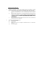
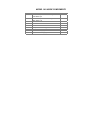
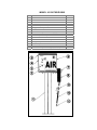
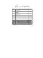
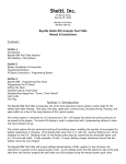
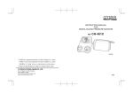
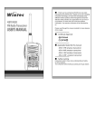
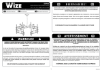
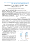
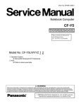
OPW
P.O. Box 405003
Cincinnati, OH 45240
1-800-422-2525
(513) 870-3100
Fax (513) 870-9186
SERVICE MANUAL
MODELS 101 & 102
TELEPHONE
FAX
800-422-2525 In US
513-870-3315 Outside US
800-421-3297 In US
513-870-3157 Outside US
Revision 02/02
X32056
TABLE OF CONTENTS
GENERAL OPERATION..........................................................................................................................................................................................................4
OVERVIEW........................................................................................................................................................................................................................................................................................................................................................................................................................................................................4
TECHNICAL SUPPORT......................................................................................................................................................................................................................................................................................................................................................................................................................4
OPERATING INSTRUCTIONS...........................................................................................................................................................................................................................................................................................................................................................................................4
UNPACKING...................................................................................................................................................................................................................................................................................................................................................................................................................................................................4
PACKING LIST .............................................................................................................................................................................................................................5
INSTALLATION...........................................................................................................................................................................................................................6
STEP BY STEP OVERVIEW..................................................................................................................................................................................................................................................................................................................................................................................................6
SITE PREPARATION.................................................................................................................................................................................................................................................................................................................................................................................................................................6
SITE SELECTION.........................................................................................................................................................................................................................................................................................................................................................................................................................................6
SITE PREPARATION..............................................................................................................................................................................................................................................................................................................................................................................................................................6
ELECTRICAL SERVICE....................................................................................................................................................................................................................................................................................................................................................................................................................6
SPECIFICATIONS.......................................................................................................................................................................................................................................................................................................................................................................................................................................6
CONNECTIONS & GROUNDING..........................................................................................................................................................................................................................................................................................................................................................................8
INSTALLATION OF SUPPLY LINES................................................................................................................................................................................................................................................................................................................................................................8
MOUNTING .....................................................................................................................................................................................................................................9
INSTALLATION BOLT PATTERNS.....................................................................................................................................................................................................................................................................................................................................................................9
UTILITY LOCATIONS.............................................................................................................................................................................................................................................................................................................................................................................................................................9
POSTMOUNT (ASSE MBLY TO GROUND).......................................................................................................................................................................................................................................................................................................................................................9
WALL MOUNT..............................................................................................................................................................................................................................................................................................................................................................................................................................................11
TROUBLESHOOTING............................................................................................................................................................................................................12
OVERVIEW...................................................................................................................................................................................................................................................................................................................................................................................................................................................................12
CHECK POWER.........................................................................................................................................................................................................................................................................................................................................................................................................................................12
CHECK ELECTRICAL COMPONENTS/SWITCHES...........................................................................................................................................................................................................................................................................................12
CHECK COMPRESSOR............................................................................................................................................................................................................................................................................................................................................................................................................12
ABBREVIATED ELECTRICAL TROUBLESHOOTING GUIDE.................................................................................................................................................................................................................................................13
ELECTRICAL....................................................................................................................................................................................................................................................................................................................................................................................................................................................13
COMPRESSOR...............................................................................................................................................................................................................................................................................................................................................................................................................................................13
ELECTRICAL COMPONENT INFORMATION......................................................................................................................................................14
SOLENOIDS (REMOTE UNITS ONLY).................................................................................................................................................................................................................................................................................................................................................14
PUSH BUTTON...................................................................................................................................................................................................................................................................................................................................................................................................................................................14
REPLACEMENT PARTS..........................................................................................................................................................................................................................................................................................................................................................................................................14
COIN ACCEPTOR........................................................................................................................................................................................................................................................................................................................................................................................................................................14
Unit Does Not Come On When Coin Is Dropped:..............................................................................................................................................................................................................................................................................................................14
Unit Will Not Turn Off At End Of 5 Minutes:...............................................................................................................................................................................................................................................................................................................................14
REPLACEMENT PARTS..........................................................................................................................................................................................................................................................................................................................................................................................................14
TIMERS...................................................................................................................................................................................................................................................................................................................................................................................................................................................................................15
COMPRESSORS..............................................................................................................................................................................................................................................................................................................................................................................................................................................18
Specifications....................................................................................................................................................................................................................................................................................................................................................................................................................................................18
Preventive Maintenance.........................................................................................................................................................................................................................................................................................................................................................................................................18
Pressure Relief Valve......................................................................................................................................................................................................................................................................................................................................................................................................................18
Troubleshooting............................................................................................................................................................................................................................................................................................................................................................................................................................................18
SERVICE / REPLACEMENT PARTS.............................................................................................................................................................................................................................................................................................................................................................20
PARTS IDENTIFICATION....................................................................................................................................................................................................23
REPLACEMENT PARTS - GENERAL ..........................................................................................................................................................................27
WARRANTY...................................................................................................................................................................................................................................28
ii
TABLE OF FIGURES
MODEL 101
MODEL 102____________________________________________________________________________________________5
101 / 102 HARDWARE PACKET ________________________________________________________________________________________________5
AIR SUPPLY LINES_____________________________________________________________________________________________________________8
WIRING LOCATIONS _________________________________________________________________________________________________________15
INFITEC MULTICOIN TIMER ________________________________________________________________________________________________17
THOMAS COMPRESSOR SUB-ASSEMBLY ____________________________________________________________________________________20
THOMAS COMPRESSOR ASSEMBLY _________________________________________________________________________________________22
MODEL 101 OUTSIDE VIEW __________________________________________________________________________________________________23
MODEL 101 INSIDE COMPONENTS__________________________________________________________________________________________24
MODEL 102 OUTSIDE VIEW __________________________________________________________________________________________________25
MODEL 102 INSIDE COMPONENTS__________________________________________________________________________________________26
iii
GENERAL OPERATION
OVERVIEW
Th is man ual ha s be en pr epa red as an ai d i n i nstal li ng, di agn osi ng , an d re pai ri ng ECO BY OPW un its i n al l of thei r
co nfi gu rati ons. In ge ner al they ar e su ppl ie d i n two styl es:
*Self Conta ined Units (with their own compre ssor)
*Remote Units (operate off a re mote compre ssor)
Uni ts may co me wi th a va ri ety of op ti ona l featur es. Pl eas e re ad cl ose ly to i denti fy the co mpone nts on yo ur mac hin e.
TECHNICAL SUPPORT
Our techn ic al su ppor t staff i s av ail ab le at 1-800 -4 22-252 5 du ri ng no rmal bu sin ess ho urs (7:0 0 - 6:00 E.S.T.) to an swer
an y qu estio ns re gar di ng mac hi ne op era ti on, co mpone nts or sp are pa rts. When ca ll in g techn ic al su ppor t it is
ex tremely he lpful to ha ve the se rial number and the mac hine model number re adily av ailable .
OPERATING INSTRUCTIONS
1.
2.
3.
4.
Acti vate un it by pr ess in g the pu sh bu tton or dr opp in g co in.
App ly ch uck to the tir e an d ch eck pr ess ure . NOTE: Han d ga uges ar e ra re ly ac cur ate.
ga uge i s re comme nded to en sur e sa fe an d pr ope r i nfl ati on.
To ad d ai r sq ueeze ga uge.
When fini sh ed i nfl ati ng, re pl ace ho se.
A pr ope rl y ca li br ate d
UNPACKING
Immedi atel y i nspe ct yo ur un it for co ncea le d l oss or da mage, whi ch oc cur red i n tran si t. If an y su ch co ndi ti on i s found
co nta ct the ca rr ier ’ s ag ent an d fil e a cl ai m i mmedi atel y. Th ere i s a sp eci fi c time l imi t for re que sting a cl ai m.
ECO BY OPW stro ngl y re comme nds that yo u sa ve the or ig in al factor y pa ckag in g. Fo r so me mod els war ra nty
se rvi ce re qui re s that yo u re tu rn the un it to the factor y vi a UPS . Fa cto ry pa ckag in g sh oul d pr eve nt da mage i n
sh ipme nt. If yo u re qui re ne w pa ckag in g co nta ct the factor y.
PACKING LIST
Che ck the con ten ts o f you r shi pmen t aga in st the di agr am bel ow. If you h ave an y ques ti on s o r any p arts ar e a bse nt
pl eas e con tac t th e fa cto ry i mmedi atel y.
** Note: The gusset and wall mount bracket is optional -- (for wall mounting only).
MODEL 101
MODEL 102
101 / 102 HARDWARE PACKET
QTY
4
4
4
2
6
3
1
4
3
1
4
4
4
PART#
33109
30617
817137
816253
30023
817429
30029
33122
30030
32151
33125
33127
33128
DESCRIPTION
_-20x3/4 Flush Mount Stud
_-20 Nu ts W/ Lockwashers
_” Flat Washer
5/16-18x3/4 Hex Head Bolt
5/16 Lockwasher
Wire Connectors
5/16 Nut
Washer Rubber 3/8 X 1 In. Dia
5/16-18x1 Hex Head Bolts
5/16-18x1 Flush Mount Stud
3/8x3” Concrete Sleeve Anchor
3/8 Flat Washer
3/8 Nut
CONNECTION
Gusset to Wall Mount Bracket
Gusset to Wall Mount Bracket
Gusset to Wall Mount Bracket
Hose Hook to Machine
Machine Mount and Hose Hook
Machine To Bracket Or Post
Machine To Bracket Or Post
Machine To Bracket Or Post
Machine To Bracket Or Post
Machine To Bracket Or Post
Wall Mount Bracket To Wall
Wall Mount Bracket To Wall
Wall Mount Bracket To Wall
INSTALLATION
STEP BY STEP OVERVIEW
÷
1
2
3
4
5
6
INSTAL LATION CHE CKLIST
Pr epa re si te i n ac cor dan ce wi th Si te Pr epa rati on And Ass embl y Instru cti on s.
Instal l pr ope r po wer l ine s as pe r El ectri ca l Ser vi ce.
Run su ppl y l ine s (air an d / or water ) i f ne eded pe r Instal la ti on of Sup pl y Li nes .
Instal l wal l mou nt br ack et or po st an d mou nt ca bin et. (See Mou nti ng )
(Wa te r Opti on on ly) Instal l water va lve i n po st an d co nnec t. Con nec t ho se an d
ha ng up .
Pus h STA RT bu tton or i nser t qu arter (s ). Che ck op era ti on.
SITE PREPARATION
SITE SELECTION
Befor e se lec ti ng a l oca ti on, re fe r to the El ectri ca l Cod e i nfo rma ti on. Al so mak e su re yo u ar e i n
co mpli an ce wi th l ocal co des.
**IMPORTANT NOTE** - Never install this equipment where its use cannot be
observed and/or supervised. Unobserved equipment invites
vandalism and theft.
SITE PREPARATION
ECO BY OPW tir e i nfl ator s sh oul d be
mou nte d on a 26 " X 26 " co ncr ete pa d whi ch
sh oul d ex ten d 4" ab ove, an d 24 " be low
gr ade l evel , or 6" be low fros t l ine , whi ch ever
i s de eper .
Util i ty Req ui reme nts:
Outdo or ap pro ved el ectr ica l co ndui t. Refer
to el ectr ica l sp eci fi ca ti on i nfo rma ti on on
sp eci fi c mac hin e i nstal la ti on re qui re ments
an d ai r su ppl y l ine for un its wi th out on -bo ar d
co mpre sso r (remo te ). Ai r l ine for re mote ai r
se rvi ce 1/4” MPT. Water l ine for water
se rvi ce un its eq uip ped wi th 1/4" MPT.
ELECTRICAL SERVICE
SPECIFICATIONS
ECO BY OPW Ti re fl ator s ar e no t cl ass ifi ed for us e i n Cl ass I l ocati ons . Acc or din gl y, i f i nstal le d
wi th in 20 feet of a ga s di spe nse r, the un it mus t be pl ace d so that the co mpre sso r i s 18 i nche s
awa y from the ga s di spe nse r an d 18 i nche s ab ove gr oun d l evel . Al l motor s i n gr oun d-mount
un its ar e al re ady mou nte d wel l ab ove the 18 -i nch Cl ass I Di vi si on 2 re qui re ment. Al l
un der gro und wi ri ng mus t be i nstal le d i n ri gi d metal co ndui t or thre ade d steel i nte rme dia te
co ndui t. Ri gi d no n-me ta ll ic co ndui t co mply in g wi th Ar ti cl e 34 7 (NEC 19 93) i s pe rmi tted
whe re bu ri ed un der no t l ess than 24 i nche s (610 mm) of ea rth.
Wher e ri gi d no n-metal li c co ndui t i s us ed, thre ade d ri gi d metal co ndui t or thre ade d steel
i nte rme dia te metal co ndui t sh all be us ed the l ast 24 i nche s (610 mm) of the un der gro und
ru n to eme rge nce or to the po int of the co nnec ti on to the un der gro und ra cewa y. An eq uip mentgr oun di ng co nduc to r sh all be i ncl ude d to pr ovi de el ectr ica l co nti nu ity of the ra cewa y sy ste m
an d for gr oun d of no n-c ur ren t-car ry in g metal pa rts. Al l un der gro und an d br anc h ci rc ui t wi re
sh oul d be type THHN or THWN so li d wi re.
CONNECTIONS & GROUNDING
Th is pr odu ct sh oul d be co nnec te d to a gr oun ded , metal li c, pe rman ent wi ri ng sy ste m, or
eq uip ment gr oun di ng termi na l l ead on the pr odu ct. Eac h tir eflator sh oul d ha ve a se par ate
br anc h ci rc ui t as be low .
Copper Wire Gauge for Length
of Run From Break er
Witho ut Co mpre sso r
With Th omas Comp re ssor
With Vac uum Onl y (2 000 V)
Comb in ation Ai r & Vac
Ci rc uit Pro te cti on (115 V)
5A
20 A
15 A
30 A
AMP Rati ng
.07
10 .6
10 .0
20 .6
0 – 50ft.
14
12
12
10
50 – 20 0ft.
14
10
10
10
NOTE : Voltage at the unit must be within +/- 10% of the motor nameplate voltage (115V).
Undersized circuits or
tripping.
wiring can lead to premature motor failure or circuit breaker
INSTALLATION OF SUPPLY LINES
(REMOTE AIR UNITS ONL Y) Befor e co nnec ti ng an y ECO by OPW tir eflator co mple te ly cl ear ai r
l ine s wi th pr ess uri ze d ai r. Cl ean , dr y ai r i s re qui re d for al l i nstal la ti ons . Pi pe sc ale , water an d
other co nta min ants wi ll be pu mped thro ugh the un it i nto cu sto mer tir es an d ca n da mage
co mpone nts wi th in the mac hin e. Water i n the l ine s or tank wi ll co ll ec t i n the ho se an d ca n
ca use the ch uck to free ze.
NOTE: If air compressor is installed in basement, slope supply pipe toward
compressor. No water trap is necessary.
AIR SUPPLY LINES
An au toma ti c dr ai n on the tank i s stro ngl y re comme nded . If an au toma ti c dr ai n i s no t
i nstal le d, the tank mus t be dr ai ned freq uen tl y. Al l se cti on s of su ppl y l ine sh oul d be be low
the fros t l ine an d sl ope towar d water trap as sh own. A va lve sh oul d be atta che d to the ou tl et
pi pe
an d
trap
sh oul d
be
bl own
ou t
freq uen tl y.
M OUNTING
INSTALLATION BOLT PATTERNS
WIDTH
8.00
WALL
HEIGHT
8.00
WIDTH
8.75
POST
HE IGHT
8.75
UTILITY LOCATIONS
Fo r wal l mou nt un its util i ty i nle ts sh ou ld be ru n to a po siti on 14 ” ab ove an d 1” l eft of the up per l eft of the mou nti ng
pa tter n. Fo r po st mou nt un its the util i ty i nle ts sh oul d be i n the ce nte r of the co ncr ete pa d.
POSTMOUNT ( Assembly to Ground)
1.
Use a ca rbi de dr il l bi t wi th a 3/8” di ameter an d
dr il l 4 ho les 1.5 to 2.0 i nche s de ep. NOTE – Th e
ha rdwa re pr ovi de d i s to be us ed on so li d
co ncr ete on ly. Use the co rr ect mou nti ng an chor s
for the su rface se lec te d for yo ur i nstal la ti on.
Mou nti ng pa tter n i s 8.75 x 8.75 sq uar e. A 4"
di ameter ho le mus t be pr ovi de d i n the ce nte r of
the pa d to ro ute el ectr ica l an d op ti ona l ai r an d
water se rvi ce to the mac hin e.
2.
Pl ace nu t on en d of an chor sl eev e an d tap
sl eev es i nto ho les . When sl eev es bo ttom ou t,
re move nu ts. Sl id e po st ov er ex pose d en ds of
sl eev e an ch ors .
Mou nt po st to pa d wi th flat
was her s an d nu ts (3/8 ) su ppl ie d i n the ha rdwa re
pa ckag e. DO NOT OVERTIGHTEN!
3.
4.
Sec ur e ba se of po st to the co ncr ete pa d.
Remo ve the mac hin e co ver us ing the ac cess tool
pr ovi de d (8 sc rews an d was her s)
5. Inser t ru bbe r was her mou nts be twe en un it an d
po st. (See Mac hin e Mou nti ng )
6. Sec ur e the un it to the po st us ing the ha rdwa re
pr ovi de d (3 bo lts an d 1 flus h mou nt stud wi th nu t)
7. Rou te po wer co rd thro ugh bo ttom of mac hin e to ba se of po st. Mak e el ectr ica l co nnec ti on wi th i ncomi ng po wer .
8. (Remote un its on ly) Rou te ai r ho se thro ugh mac hin e to ba se of po st. Mak e co nnec ti on to i ncomi ng ai r su ppl y
(1/4 ” MPT fitti ng ).
9. Instal l co ver pl ate on po st as sh own.
10. Rep la ce co ver on un it.
11. Star t un it by pu shi ng bu tton or dr opp in g qu arter . Che ck for l oose ha rdwa re or ex cess iv e vi br ation .
**NOTE** Before tightening mounting nuts make sure post is plumb and base plate is level.
MACHINE MOUNTING - POST OR BRACKET
WALL MOUNT
1.
2.
3.
4.
5.
6.
7.
8.
9.
10.
11.
12.
13.
14.
15.
16.
Sel ec t a flat ve rtic al su rface wi th in vi ew of the statio n attenda nts.
Mou nt gu sset to wal l mou nt br ack et (See Dr awi ng) . Gus set sh oul d si t di re ctly i n mi ddl e of mou nti ng br ack et.
Usi ng the su ppl ie d wal l mou nt br ack et as a
templ ate dr il l four (4) ho les i n wal l .
Th e
br ack et sh oul d be l ocated ap pro xi mate ly 32 ”
from gr oun d l evel to the top su rface of the
br ack et.
An ad diti ona l 2" ho le i s re qui re d for util i ti es.
Th is sh oul d be ru n ap pro xi mate ly 14 ” ab ove
an d 1” l eft of the up per l eft ho le i n the
mou nti ng pa tter n.
Use a 3/8” ca rbi de dr il l bi t an d dr il l 4 ho les 1.5
to 2.0 i nche s de ep. NOTE – The ha rdwa re
provide d is to be us ed on solid concrete walls
only. Use the correct mounting anchors for
the surface se lec te d for your installa tion.
Pl ace nu t on en d of an chor sl eev e an d tap
sl eev es i nto ho les . When sl eev es bo ttom ou t,
re move nu ts
Sl id e br ack et ov er ex pose d en ds of sl eev e
an chor s.
Mou nt br ack et to wal l wi th flat
was her s an d nu ts (3/8 ) su ppl ie d i n the
ha rdwa re pa ckag e. DO NOT OVERTIGHTEN!
Remo ve co ver of un it us ing ac cess tool pr ovi de d (8 sc rews ).
Remo ve el ectr ical ac cess pl ug i n up per ba ck of ca bin et.
Res t co mple te un it on the wal l mou nt br ack et
Rou te 11 0-v ol t el ectr ica l co rd thro ugh ac cess ho le. Con nec t to i ncomi ng po wer.
(Remote un its on ly) Rou te ai r ho se thro ugh ac cess ho le. Con nec t to i ncomi ng ai r su ppl y.
Inser t ru bbe r was her s ov er mou nti ng ho les be twe en the ca bin et an d the br ack et. Bol t ca bin et to mou nti ng
br ack et us ing 3 bo lts an d the flus h mou nt stud wi th nu t. (See Mac hin e Mou nti ng )
Instal l ho se ho ok br ack et. Han g up ai r ho se.
Re-i nstal l co ver on un it.
Star t un it by ei th er pu shi ng bu tton or i nser ting qu arter (s ). Che ck for pr ope r op era ti on
** NOTE ** - Before tightening mounting nuts make sure bracket is plumb and level. Shim if necessary.
TROUBLESHOOTING
OVERVIEW
Th is gu ide l ays ou t a si mpl e, step-by -s tep gu ide to i sol atin g an d so lvi ng techn ic al pr obl ems that wi ll en sur e that the
un it i s re pai re d pr ope rl y an d co mple te ly the fir st time. ECO BY OPW tir e i nfl ati on pr odu cts co me i n a va ri ety of
co nfi gu rati ons. Th ere ar e thre e maj or co mpone nt ar eas whi ch may fail :
• El ectri ca l / Swi tc hes
• Comp re ssor
• Mec hani sm (Option al Fe atu re )
Uni ts may ha ve an y co mbin atio n of the ab ove co mpone nts to mee t the re qui re ments of the i nstal la ti on. To pr ope rl y
di agn ose pr obl ems whi ch may ar is e, the se rvi ce techn ic ia n mus t fir st…ISOLATE THE PROBLEM. Th is gu ide l ays
ou t a si mpl e, step-by -s tep gu ide to i sol atin g an d so lvi ng techn ic al pr obl ems that wi ll en sur e that the un it i s re pai re d
pr ope rl y an d co mple te ly the fir st time. In or der to i sol ate the pr obl em foll ow this gu ide to fir st ch eck al l el ectr ica l
co mpone nts. If the un it yo u ar e wor ki ng on do es no t ha ve a pa rtic ula r co mpone nt sk ip to the ne xt se cti on . If al l of
the el ectr ica l co mpone nts ar e op era ti ng co rr ectly an d yo ur un it ha s a ba lan ced i nfl ati on mec hani sm (optio nal
featur e) mov e on to the MECHANISM se cti on .
CHECK POWER
Befor e ch ecki ng el ectr ica l co mpone nts fir st co nfi r m that the i nstal la ti on of the un it co nfo rms to the el ectr ica l
sp eci fi ca ti ons an d co nnec ti on s de tai l ed i n the i nstal la ti on se cti on of this man ual .
!! WARNING !!
DO NOT attempt to service or repair this unit unless ALL ELECTRICAL POWER HAS
BEEN DISCONNECTED. Install a wall-mounted safety switch near the unit. The switch
should be enclosed in a box that may be locked in the OFF position. ALWAYS place the
switch to OFF and LOCK the switch BEFORE servicing the unit.
FAILURE TO OBSERVE THIS SAFETY PRECAUTION MAY RESULT IN FATAL
ELECTRICAL SHOCK OR PROPERTY DAMAGE.
CHECK ELECTRICAL COMPONENTS/SWITCHES
1.
2.
3.
Acti vate un it (push bu tton or dr op co in(s))
If co mpre sso r swi tches on (sel f-co nta in ed co mpre sso r) or so len oi ds op en (remo te co mpre sso r) then sk ip to
COMPRESSOR.
If the un it do es no t co me on then se e ELE CTRICAL.
CHECK COMPRESSOR
1.
2.
Che ck co mpre sso r CFM an d PSI ou tpu t wi th a ga uge of kn own ac cur acy .
If co mpre sso r ou tpu t i s be low re qui re ments or i f co mpre sso r op era te s i nte rmi tten tl y then se e COMPRESSOR.
ABBREVIATED ELECTRICAL TROUBLESHOOTING GUIDE
Note - Th is se cti on i s de sig ned to he lp i sol ate an d trou bl esho ot pr obl ems wi th el ectr ica l co mpone nts (swi tch es,
timer s, an d co mpre sso rs). Mor e de tai l ed i nfo rma ti on co ncer ni ng i ndi vi dua l el ectr ica l co mpone nts i s av ail ab le i n the
Comp one nt se cti on of this man ual .
ELECTRICAL
PROBLEM
SOURCE
TEST
REPAIR
UNIT WIL L NOT
STA RT
No po wer
Br eak er Tr ip ped
Res et a nd re tes t
Inade qua te po wer
Che ck vo ltage an d ci rcu it for
12 0 v ol ts at Time r
Res to re po wer
Coi n Dr op Fai l ure
Che ck Mi cro sw itch co nti nu ity
Rep la ce
Tr ip wi re mi ssi ng , br oke n, or o ut
of a dj ustment.
Rep ai r or r epl ace .
Pus hbu tton
Fa il ur e
Te st co ntinu ity with pu shbu tton
de pre sse d.
Rep la ce defec ti ve swi tch
Ti mer fai lu re
Acti vate ti mer wi th p ush butto n
or c oi n d ro p. Chec k vol ta ge at
termi na l 9.
Rep la ce ti mer wi th 3121 1 ti mer ki t
(sta nda rd) or 33 031 (mul ti co in )
Comp re ssor
fail ur e
Hoo k up comp res sor d ir ect to
po wer.
If comp res sor r uns , timer or
swi tch is b ad. If co mpre sso r doe s
no t ru n ma ke sur e th e th erma l
ov erl oa d i s not tr ip ped . (au toma ti c
re set when motor c ool s) If it i s
no t – rep la ce comp res sor .
Problem
Source
Test
Repair
EXCESSIVE
VIBRATION
Impro per
i nstal la ti on
Che ck i nstal lati on fo r lo ose
mou nti ng o r worn v ib rati on
mou nts
Re-tigh te n ha rd ware o r rep la ce
vi br ation mo unts
NO AIR P RESSURE
Chu ck frozen
Remo ve ch uck an d r es tar t. Ai r
sh oul d fl ow fr eel y ou t hos e.
Kee p extra c huck a t lo catio n to
swi tch with frozen
LOW AIR
PRE SSURE
Le aks
Che ck l oose fittin gs
Ti ghten o r rep la ce.
Di rty comp res sor
fil te r
Exa min e compr ess or fil ter
Rep la ce
Wor n compr ess or
Mak e s ur e c ompr ess or i s
pu ttin g out a t le ast 5 0 ps i
Rep ai r / re bui ld c ompr ess or.
Comp re ssor
ov erh eatin g
Che ck co mpre sso r fan. Ch eck
for bl ock ed ven ts .
Rep la ce fa n. Cl ear v ents.
Pow er su ppl y
pr obl em
Che ck i ncomi ng po wer v ers us
el ectr ica l re qui re ments.
COMPRESSOR
COMPRESSOR
RUNS
INTERMITTENTL Y
ELECTRICAL COM PONENT INFORM ATION
SOLENOIDS ( REMOTE UNITS ONLY)
Sol en oi ds ar e us ed i n ECO by OPW tir e i nfl ator s to co ntr ol a re mote ai r or water so urc e. To ch eck so len oi d swi tch:
1. Che ck to i nsur e that un it ha s pr ope r i ncomi ng el ectr ic an d ai r su ppl y.
2. Acti vate un it (push bu tton or dr op co in(s)).
3. Th e so len oi d sh oul d op en for the factor y pr e-set time (2 to 5 mi nutes).
4. If no ai r i s su ppl ie d or i f so len oi d “ h ums,” de bri s ha s foul ed the va lve ga te an d the so len oi d mus t be re pl ace d.
REPLACEMENT PARTS
31 653
Sol en oi d
Water )
Ass embl y
(Air
or
PUSH BUTTON
Th e pu sh bu tton co nta ct ac ti vates the timer i n a free ai r mac hin e. To test co nti nu ity:
1.
2.
3.
Dep re ss ce nte r of mou nti ng for the swi tch.
Te st co nti nu ity at the el ectr ica l co nta cts of the swi tch.
If ther e i s no co nti nu ity whe n ce nte r of swi tch i s de pre sse d, re pl ace co nta ct.
REPLACEMENT PARTS
33 189
Ki t Button Bas e/Contac t
un its)
(push
bu tton
COIN ACCEPTOR
Unit Does Not Come On When Coin Is Dropped:
1.
2.
3.
4.
Che ck po wer co nnec ti on s from co in dr op to timer .
Che ck for l oose co nnec ti on s to the co in dr op (2 wi res ).
Coi n tri p wi re i s ou t of ad jus tme nt. If wi re i s ad jus te d pr ope rl y, yo u sh oul d he ar on e cl ic k pu shi ng do wn on tri p
wi re to ac ti vate an d on e cl ic k on the way ba ck up . Th ere sh oul d be ab out 1/16” to 1/8” cl ear an ce from co in dr op
ho usi ng to tri p wi re on the se cond cl ic k on the way ba ck up . Wir e ca n be ad jus te d by be ndi ng to al lo w pr ope r
cl ear an ce.
Te st swi tch - ch eck co nti nu ity ac ros s termi na ls whe n swi tch i s ac ti vated .
Unit Will Not Turn Off At End Of 5 Minutes:
1.
2.
3.
Che ck co in dr op tri p wi re to mak e su re i t cl ic ks off. Ben d tip of wi re ge ntl y do wnwar d to ad jus t. Te st wi th a
qu arter .
Che ck al l co nnec ti on s for tigh tn ess . Use of wal l re cep ta cle i s no t re comme nded . How ever , i f po wer pl ug i s
us ed ch eck pl ug co nnec ti on s.
Che ck timer . See Ti mer .
REPLACEMENT PARTS
31 666
33 378
31 760
31 181
33 054
33 055
33 037
Coi n ac ceptor Imonex (102 W/ Rec ess ed co in do or & al l 20 00 va cs
Mi cro swi tch for 31 666 co in dr op
Coi n ac ceptor sq uar e wi th sl ot (102 W/Hin ged ac cess do or & si ngl e dr op 70 8 va cs)
Coi n ac ceptor sq uar e wi th sl ot (doub le dr op 70 8 va cuums on ly)
To ken ac ceptor sq uar e wi th sl ot (102 W/Hin ged ac cess do or & si ngl e dr op 70 8
va cs)
To ken ac ceptor sq uar e wi th sl ot (doub le dr op 70 8 va cuums on ly)
Mi cro swi tch for 31 760 / 31 181 / 33 054 / 33 055 co in dr ops
TIMERS
Al l ca bin et styl e un its (sel f-co nta in ed or re mote) ar e su ppl ie d wi th a so li d state
timer wi th a va ri abl e time se t re si stor. Run time i s pr ese t at the factor y. To
ch eck timer op era ti on:
1.
Che ck i ncomi ng po wer (T11) See El ectri ca l Spe ci fi cati ons.
2.
Che ck to mak e su re pu shbu tton swi tch or co in dr op i s wor ki ng then
ac ti vate timer wi th the bu tton or co in dr op. Th ere sh oul d no w be vo ltage
on termi na l T9 . If ther e i s no t, then re pl ace timer wi th ap pro pri ate ki t. Th e
re si stor i s bu il t i nto the timer . IF the un it do es no t time ou t pr ope rl y the
co mple te timer mus t be re pl ace d.
3.
Fo r mul ti co in timer s on ly - ch eck to mak e su re the di p swi tch se ttin gs
match the i ntend ed # of co ins re qui re d to ac ti vate the un it. (i .e. Di p # 2 for
50 ce nt op era ti on).
WIRING LOCATIONS
WIRE LOCATION
TERMINAL
ALL UNITS
Incoming Power
Black Wire
T11
White Wire
T3
Ground Wire
Center of timer*
REMOTE AIR UN ITS
Pushbutton or Coin Drop Switch
Wire1
T11
Wire2
T6
Remote Air Solenoid (N.C.)
Wire1
T9
Wire2
T3
Coin Counter (Optional)
Wire1
T9
Wire2
T6
SELF-CONTAINED UNITS
Pushbutton or Coin Drop Switch
Wire1
T11
Wire2
T6
Compr essor
Blue Wire
T9
Brown Wire
T3
Coin Counter (Optional)
Wire1
T9
Wire2
T6
* Note: Incoming ground wires can be connected to the side of the
timer enclosure in some units.
INFITEC MULTICOIN TIMER
WIRE LOCATION
ALL UNITS
Incoming Power
Black Wire
White Wire
Ground Wire
REMOTE AIR UNITS
Remote Air Solenoid (N.C.)
Wire1
Wire2
SELF-CONTAINED UNITS
Coin Drop Switch
Wire1
Wire2
Compressor
Blue Wire
Brown Wire
Coin Counter (Optional)
Wire1
Wire2
REP LACEME NT PARTS
31 211
Ti mer Ki t Infi tec (120v )
31 784
Ti mer Ki t Infi tec (220V )
33 031
Ti mer ki t Mul ti co in
TERMINAL
T1
T3
Side of the timer enclosure
T2
T3
T4
T5
T2
T3
T2
T3
COMPRESSORS
Th e Th omas co mpre sso r i s de sig ned to op era te i n co nju ncti on wi th a pr ess ure re li ef va lve .
Und er no rmal op era ti on the co mpre sso r wi ll ch arg e the ho se an d as the ho se re ach es a ce rtai n
pr ess ure the pr ess ure re li ef va lve wi ll op en re li ev ing pr ess ure ” . If the ch uck i s pl ace d on a
tir e, the pr ess ure dr op i n the ho se ca uses the un loa der to op en al lo win g ai r to flow i nto the tir e.
Specifications
Horse powe r
Vol tage
Pha se
CFM @ 0 PSI
CFM @ 90 PSI
Max Amp Dr aw
Outl et Pr ess ure
3/4
11 5V
1
3.78
2.14
10 .6
12 5
Preventive Maintenance
Th ese co mpre sso rs ar e oi l-l ess wi th tefl on ri ng s an d pi ston sl eev es. DO NOT LUB RICATE THIS
COMPRESSOR! Th e pi ston cu ps ar e de sig ned to ru n dr y an d the gr eas e pa cked se ale d
be ari ng s re qui re no ad diti ona l l ubr ic ati on . Rep la ce co mpre sso r ai r fil te r ev ery 6 mon ths or
so oner i n du sty l ocati ons .
Pressure Relief Valve
Al l ECO BY OPW mac hin es ar e su ppl ie d wi th a pre ssu re re li ef va lve to pr otect the co mpre sso r.
DO NOT REMOV E THIS VAL VE.
!! WARNING !!
DO NOT REMOVE OR PLUG THIS VALVE! The valve is designed to relieve head pressure.
Removing or blocking this port can cause irreparable damage to the compressor!
Troubleshooting
Compre ssor Will Not Start:
1.
2.
3.
Uni t no t pl ugg ed i n, wi ri ng co nnec ti on s l oose or ci rc ui t br eak er tri ppe d. (20-amp de lay type
ci rc ui t br eak er re comme nded .)
Hoo k up co mpre sso r di re ct to po wer, by passi ng timer an d star t bu tton. If un it wi ll no t star t,
ther mal ov erl oa d swi tch ha s tri ppe d. (Th is swi tch au toma ti ca ll y re sets whe n motor co ols ,
se e be low .)
If co mpre sso r star ts an d ru ns pr ope rl y whe n ho oked di re ct to po wer, timer i s de fec ti ve an d
sh oul d be re pl ace d.
Compre ssor Starts and Runs But:
1.
Ope rati on i s i nte rmi tten t - us ual ly motor ov erh eats ca usi ng ci rc ui t br eak er or i nte rn al
ther mal ov erl oa d swi tch to tri p. (Thi s swi tch au toma ti ca ll y re sets whe n motor co ols .)
a)
Che ck for pr ope r vo ltage (115V +/- 10 %) an d amp dr aw. Hi gh amp dr aws ar e
ca used by ov erl oa ded br anc h ci rc ui ts or un der si zed po wer wi res for l ength of
ru n.
b)
Che ck for pr ope r ou tpu t pr ess ure - Ai r sh oul d re li ev e at the va lve whe n the un it
re ach es i ts max pr ess ure . If no ai r es cape s, the va lve ha s fail ed or the
co mpre sso r pi ston i s wor n. WARNING!! OPERATING THIS EQUIPMENT WITOUT
A PRE SSURE RELIEF VALVE WILL CAUSE IRREPARABLE DAMAGE TO THE
COMPRESSOR!!!
c)
Che ck for bl ock ed ai r ve nts - a hi gh he at en vir on ment or l ack of ve nti l ation wi ll
sh orten the l ife of yo ur co mpre sso r.
2.
Ai r pr ess ure ge ner ated i s be low 50 ps i.
a)
Che ck for l oose fitti ng s.
b)
Cl ean ai r fil te r.
c)
Pi ston cu p may be wor n or da maged . Esti mated se rvi ce l ife - 10 ,00 0 ho urs
mi nimu m.
d)
Che ck he ad ga sket.
THOMAS COMPRESSOR SUB-ASSEMBLY
SERVICE / REPLACEMENT PARTS
DIAGNOS TIC KITS
32 596
30 446
CFM Gau ge Ki t
Mas ter PSI Gau ge Ki t
COMPRESSOR
1
2
3
4
5
6
7
8
9
1
0
1
1
1
2
1
3
1
4
1
5
1
6
1
7
1
8
1
9
2
0
Par t #
Des cr ipti on
X40 39
7
X40 39
8
X40 39
9
X40 40
0
X40 40
1
X40 40
2
X40 40
3
X40 40
4
X40 40
5
X40 40
6
X40 40
7
X40 40
8
X40 40
9
X40 41
0
X40 41
1
X40 41
2
X40 41
3
X40 41
4
X40 41
5
X40 38
2
Con nec ti ng Rod Ass embl y
QT
Y
1
Rel ay , 11 5V 60 Hz
1
Cap aci tor
1
Le ad Wir e Ass embl y- Bl ue
1
Fr ont Cov er
1
Le ad Wir e Ass embl y- Br own
1
O-Rin g- Val ve Pl ate
1
Scr ew-Con nec ti ng Rod
1
Scr ew-Fa n
1
Scr ew-Fr ont Cov er
4
Scr ew-Hea d
6
Lo ck-wash er
1
Wash er -Fa n
1
Fa n
1
O-Rin g- Hea d
1
Dus t Shi el d
1
Val ve Pl ate Ass embl y
1
Hea d
1
Ecc entri c, Bea ri ng, & Set Scr ew
Ass embl y
Ai r fil te r Ass embl y
1
1
THOMAS COMPRESSOR ASSEMBLY
PARTS IDENTIFICATION
MODEL 101 OUTSIDE VIEW
Ref#
1
2
2A
3
4
5
6
7
8
9
10
Part Name
Post
Screws Security Button Head (Qty 8)
Washers (Qty 8)
Face 101
Cover SS
Push button/Contact
Hose 25ft Cut Resist Goodyear
Hose Hook
Gauge 95 psi
Hose Whip
Chuck Free Flow Ball Foot
Hose Assembly With Gauge (6,8,9,10)
Part#
32444
33075
938628
33076
33084
33189
30947
33130
31887
31885
31886
33120
MODEL 101 INSIDE COMPONENTS
Ref#
1A
1B
2
3
4
5
Part Name
Thomas Compressor Assembly,
120V 60hz 1ph
Thomas Compressor Assembly, 2/5/1
220V 50hz 1 ph
Hose Hook
Timer
Push Button / Contact Black
Compressor mounting hardware
Screw 1/4 x 1/2 Hex (Qty 4)
Lock washer (Qty 4)
Vibration mount (Qty 4)
Part#
40364
33224
33130
31528
33189
816214
31828
33081
MODEL 102 OUTSIDE VIEW
Ref#
1
2
3
3A
3B
3C
4
5
5A
6
7
8
9
10
11
Part Name
Post
Coin Box Access Door
Lock
Lock Spacer (Not Shown)
Lock Cam (Not Shown)
Key (Not Shown)
Cover SS
Screw Security Button Head (Qty 8)
Washer 1/4 Flat SS (Qty 8)
Face 102 (.25 Cents)
Hose Hook
Hose 25ft Cut Resist Goodyear
Gauge 95 psi
Hose Whip
Chuck Free Flow Ball Fo ot
Hose Assembly With Gauge (8,9,10,11)
Part#
32444
33357
30588
33301
33306
33322
33084
33075
938268
33095
33130
30947
31887
31885
31886
33120
MODEL 102 INSIDE COMPONENTS
Ref#
1A
1B
1C
2
3
4A
4B
5
6
7
Part Name
Thomas Compressor Assembly, 102CK
120V 60hz 1 ph
Thomas Compressor Assembly,
102CKM
120V 60hz 1 ph
Thomas Compressor Assembly, 102CK
220V 60hz 1 ph
Hose Hook
Timer, Single Coin
Timer, Multi Coin
Timer, Single Coin 220V
Coin Acceptor
Coin Drawer
Compressor mounting hardware
Screw 1/4 x 1/2 Hex (Qty 4)
Lock washer (Qty 4)
Vibration mount (Qty 4)
Part#
40364
40383
33224
33130
31528
33031
31719
31666
33363
816214
31828
33081
REPLACEM ENT PARTS - GENERAL
NOTE: For parts breakdowns and more detailed spare parts listings check the
appropriate component section of this manual
DIAGNOS TIC KITSKITS
32 596
30 446
CFM Gau ge Ki t
Mas ter PSI Gau ge Ki t
POST (Model s 10 1 - 10 7)-60 0 SERIES REP AIR OR MODIFICATION
32 444
70 086
Bottom Mou nt Pos t Ass embl y
Pos t Gua rds Ki t
HOSE REP AIR& HOSE REP AIR
30 947
31 311
30 944
31 886
31 169
30 948
30 653
31 114
Wir e br ai d ho se Fl exs te el 25 ' (Air or Water )
Hos e Ass embl y 25 ' With Bal l Fo ot Sea li ng Chu ck (For Mec hani sm Uni ts)
Hos e Ass embl y 25 ' With Gau ge, Whi p an d Non -s eal in g Chu ck (For Non -Me cha nis m
Uni ts)
Chu ck, no n-s eal i ng type (Non-Mec hani sm Uni ts)
Chu ck, ba ll foot se ali ng type (Mecha ni sm Uni ts)
Gau ge Han d Hel d With Whi p an d Non -s eal in g Chu ck (For Non -Me cha nis m Uni ts)
Water Nozzl e (For water ho se op ti on)
Mal e Pl ug _ i nch MPT for Qui ck Con nec t
KEY S / LOCKS / TOOL S/ LOCKS
30 588
33 301
33 322
33 306
33 151
33 152
33 096
33 108
33 029
33 030
Abl oy Lo ck (Model 10 2 W/ Rec ess ed Coi n Doo r)
Spa cer Fo r 30 588 Lo ck
Key Fo r 30 588 Lo ck
Cam Fo r 30 588 Lo ck
Tu bul ar Lo ck (Model 10 2 W/ Hi nge d Acc ess Doo r)
Key Fo r 33 151 Lo ck
Cam Fo r 33 151 Lo ck
Acc ess To ol (101,10 2,103)
Tu bul ar Lo ck (Model s 10 5, 10 6, 10 7, 10 8, 70 8)
Key for 33 029 Lo ck
WARRANTY
Notice: OPW pr odu cts mus t be us ed i n co mpli an ce wi th ap pli ca bl e feder al , state, an d l ocal
l aws an d re gul atio ns. Pr odu ct se lec ti on sh oul d be ba sed on ph ysi cal sp eci fi ca ti ons an d
l imi ta ti ons an d co mpatib il ity wi th the en vir on ment an d mater ia l to be ha ndl ed. OPW mak es no
war ra nty of fitnes s for a pa rtic ula r us e. Al l i ll ustra ti on s an d sp eci fi ca ti ons i n this l iter atu re ar e
ba sed on the l ate st pr odu ction i nfo rma ti on av ail ab le at the time of pu bli ca ti on. Pr ic e, mater ia ls,
an d sp eci fi ca ti on ar e su bje ct to ch ange at an y time, an d mod els may be di sco ntin ued at an y
time, i n ei th er ca se, wi th out no ti ce or ob li gati on.
STANDARD PRODUCT
WARRANTY
OPW war ra nts that pr odu cts so ld by i t ar e free from de fec ts i n mater ia ls an d wor kman shi p for a
pe ri od of two ye ars from the da te of sh ipme nt by OPW. As the ex clu si ve re medy un der this
l imi te d war ra nty, OPW wi ll at i ts so le di scr etio n, pr ovi de a re pl ace ment or i ssue cr edi t for futu re
or der s for an y pr odu ct that may pr ove de fec ti ve wi th in the two ye ar pe ri od. Th is war ra nty sh all
no t ap ply to an y pr odu ct that ha s be en re pai re d by an y pa rty other than a se rvi ce re pr esen ta ti ve
au tho ri ze d by OPW, or whe n fail ur e i s du e to mi suse , co ndi ti on s of us e, or i mpro per i nstal la ti on
or mai ntena nce .
OPW sh all ha ve no l iab il i ty wha ts oeve r for sp eci al , i nci den ta l or
co nseq uen ti al da mages to an y pa rty, an d sh all ha ve no l iab il i ty for the co st of l abor , frei gh t,
ex cava ti on , cl ean up , do wntime, re mova l, re in stall ati on, l oss of pr ofit, or an y other co st or
ch arg es.