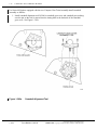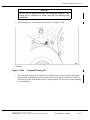
1
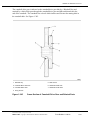
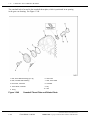
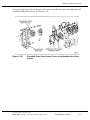
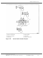
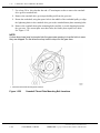
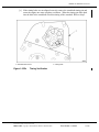
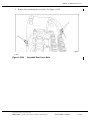
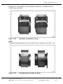
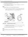
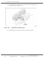
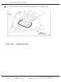
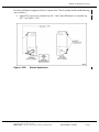
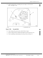
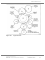
SERIES 60 SERVICE MANUAL
Figure 1-344
Engine Gear Train
All information subject to change without notice.
6SE483 0204 Copyright © 2002 DETROIT DIESEL CORPORATION
From Bulletin 11-60-02
1-427
1.23
CAMSHAFT AND CAMSHAFT BEARING
Figure 1-344a
1-428
Series 60 2002 Engine Compact Gear Train Assembly
From Bulletin 11-60-02
All information subject to change without notice.
6SE483 0204 Copyright © 2002 DETROIT DIESEL CORPORATION
SERIES 60 SERVICE MANUAL
The camshaft drive gear is indexed to the camshaft drive gear hub by a Woodruff key and
retained by a bolt which goes through the camshaft drive gear and hub and threads into the
end of the camshaft. The camshaft has a dowel which indexes and fits into the mating hole in
the camshaft hub. See Figure 1-345.
1. Woodruff Key
5. Seal Groove
2. Camshaft Drive Gear Hub
6. Camshaft Dowel Hole
3. Camshaft Drive Gear
7. Camshaft Thrust Plate
4. O-ring Groove
Figure 1-345
Cross-Section of Camshaft Drive Gear and Related Parts
All information subject to change without notice.
6SE483 0204 Copyright © 2002 DETROIT DIESEL CORPORATION
From Bulletin 11-60-02
1-429
1.23
CAMSHAFT AND CAMSHAFT BEARING
The camshaft hub is located in the camshaft thrust plate, which is positioned in an opening
in the gear case housing. See Figure 1-346.
1. Bolt, Thrust Plate Retaining (2) or (3)
6. Gear Case
2. Bolt, Camshaft Hub Retaining
7. Seal, Thrust Plate
3. Drive Gear, Camshaft
8. Camshaft
4. Thrust Plate, Camshaft
9. Key
10. Hub
5. O-ring
Figure 1-346
1-430
Camshaft Thrust Plate and Related Parts
From Bulletin 11-60-02
All information subject to change without notice.
6SE483 0204 Copyright © 2002 DETROIT DIESEL CORPORATION
SERIES 60 SERVICE MANUAL
Access openings are provided in the gear case cover for camshaft drive gear lash adjustment and
camshaft retaining bolt removal. See Figure 1-347.
Figure 1-347
Camshaft Drive Gear Access Cover and Adjustable Idler Gear
Access
All information subject to change without notice.
6SE483 0204 Copyright © 2002 DETROIT DIESEL CORPORATION
From Bulletin 11-60-02
1-431
1.23
CAMSHAFT AND CAMSHAFT BEARING
A cover is provided at the rear end of the camshaft and is secured to the No. 7 camshaft bearing
cap and the cylinder head by three bolts. See Figure 1-348.
Figure 1-348
Rear Camshaft Access Cover
Vertical oil passages at the front and rear of the cylinder head deliver oil from the cylinder block
front and rear oil galleries to the No. 1 and 7 lower camshaft bearing saddles. From there, the
oil is directed upward (through the enlarged stud hole) to the No. 1 and 7 upper bearing caps.
A drilled passage in each of these caps exits at the rocker arm shaft seat area, where it indexes
with a hole in each rocker arm shaft. The rocker arm shafts have internal oil passages that
deliver oil to the rocker arm bushings and intermediate upper camshaft bearings. Some of the
oil supplied to the rocker arm bushing passes through the oil hole in the bushing to the rocker
arm. The rocker is drilled to supply oil to the camshaft follower, roller pin, and bushing. The
rocker is also drilled to supply oil to the valve adjusting screw, valve button, retainer clip, intake,
and exhaust valve stems and the fuel injector follower. The No. 4 camshaft cap is "Y" drilled,
forming an oil path connection between the front and rear rocker arm shafts, to ensure complete
lubrication. See Figure 1-349.
1-432
From Bulletin 11-60-02
All information subject to change without notice.
6SE483 0204 Copyright © 2002 DETROIT DIESEL CORPORATION
SERIES 60 SERVICE MANUAL
1. Rocker Arm, Exhaust Valve
4. Rocker Arm Shaft
2. Rocker Arm, Fuel Injector
5. Cylinder Head
3. Camshaft Cap
6. Rocker Arm, Intake Valve
Figure 1-349
Cylinder Head Lubrication Schematic
All information subject to change without notice.
6SE483 0204 Copyright © 2002 DETROIT DIESEL CORPORATION
From Bulletin 11-60-02
1-433
1.23
CAMSHAFT AND CAMSHAFT BEARING
1.23.1
Repair or Replacement of Camshaft and Camshaft Bearing
To determine if repair or replacement of the camshaft and camshaft bearings is necessary, perform
the following procedure. See Figure 1-350.
Figure 1-350
1-434
Flowchart for Repair or Replacement of Camshaft and Related
Parts
From Bulletin 11-60-02
All information subject to change without notice.
6SE483 0204 Copyright © 2002 DETROIT DIESEL CORPORATION
SERIES 60 SERVICE MANUAL
1.23.2
Removal of Camshaft and Camshaft Bearing
Removal of camshaft and camshaft bearings as follows:
1. Remove the valve rocker cover. Refer to section 1.6.2 (one-piece), refer to section 1.6.3
(two-piece), refer to section 1.6.5 (three-piece).
2. Remove the five bolts that secure the camshaft drive gear access cover to the gear case.
See Figure 1-347.
3. Remove both rocker arm shaft assemblies. Refer to section 1.3.2.
NOTICE:
Only special tool, J 35652-B, should be used to hold the
camshaft drive gear stationary while loosening or tightening the
camshaft drive gear-to-camshaft bolt. Other tools or devices
can cause engine damage.
4. Insert the shoe of the camshaft drive gear torque holding tool, J 35652-B, through a
lightening hole of the camshaft drive gear.
5. Bar the engine over slightly to position the camshaft drive gear holding tool so that the
bolt holes in the holding tool align with the access cover bolt holes in the gear case cover,
using the 3/4 in. square hole in the center of the crankshaft pulley.
6. Install J 35652-B to the gear case, engaging one of the lightening holes in the camshaft
drive gear. Use two of the access cover bolts to secure the tool to the gear case.
See Figure 1-351.
Figure 1-351
Camshaft Drive Gear Torque Holding Tool Installation
All information subject to change without notice.
6SE483 0204 Copyright © 2002 DETROIT DIESEL CORPORATION
From Bulletin 11-60-02
1-435
1.23
CAMSHAFT AND CAMSHAFT BEARING
7. Use a long 3/4 in. drive breaker bar and a 27 mm impact socket to remove the camshaft
drive gear-to-camshaft bolt.
8. Remove the camshaft drive gear torque holding tool from the gear case.
9. Rotate the crankshaft, using the square hole in the middle of the crankshaft pulley, to align
the lightening holes in the camshaft drive gear to the camshaft thrust plate mounting bolts.
10. Remove the camshaft thrust plate mounting bolts carefully, to avoid dropping them into
the gear case. The current plate uses three bolts, the former plate requires two bolts.
See Figure 1-352.
NOTE:
A clean shop towel may be inserted into the gear case opening to trap the bolts in case
they are dropped. Do not allow the shop towel to drop into the gear case.
1. Camshaft Thrust Plate Mounting Bolt Locations
Figure 1-352
1-436
Camshaft Thrust Plate Mounting Bolt Locations
From Bulletin 11-60-02
All information subject to change without notice.
6SE483 0204 Copyright © 2002 DETROIT DIESEL CORPORATION
SERIES 60 SERVICE MANUAL
11. Install J 35906, to the camshaft drive gear access opening, using three of the access
cover bolt holes. Engage the puller screw in the threads of the camshaft drive gear hub,
until the screw is tight. See Figure 1-353.
Figure 1-353
Camshaft Thrust Plate Remover
All information subject to change without notice.
6SE483 0204 Copyright © 2002 DETROIT DIESEL CORPORATION
From Bulletin 11-60-02
1-437
1.23
CAMSHAFT AND CAMSHAFT BEARING
12. Continue turning the puller screw to pull the camshaft drive gear hub and thrust plate
forward approximately 6-7 mm (1/4 in.) until the thrust plate seal is clear of the camshaft
front bearing cap and cylinder head. See Figure 1-354.
Figure 1-354
Camshaft Thrust Plate Clearance
13. Remove the three bolts that secure the rear camshaft cover to the engine and remove
the cover.
1-438
From Bulletin 11-60-02
All information subject to change without notice.
6SE483 0204 Copyright © 2002 DETROIT DIESEL CORPORATION
SERIES 60 SERVICE MANUAL
14. Remove the remaining seven camshaft cap bolts. Remove the No. 1 and 7 studs using
socket tool, J 36003 part of J 36003–A. See Figure 1-355.
Figure 1-355
Camshaft Cap Stud Removal
15. Remove the seven camshaft bearing caps and the upper bearing shells. Keep the caps and
shells together for possible later installation. Tag the bearing cap location, as they must
always be installed in the same location.
16. The camshaft gear pilot tool will remain in place, holding the camshaft drive gear
in contact with the adjustable idler gear, to prevent accidental disengagement. This
arrangement makes it unnecessary to re-time the gear train.
NOTE:
The camshaft gear can go out of time if the pilot tool is removed.
17. Slide the camshaft rearward to completely disengage the dowel from the hub. Lift out
the camshaft.
18. Remove the lower camshaft bearing shells, and group them with the upper shells and
caps for possible reuse.
All information subject to change without notice.
6SE483 0204 Copyright © 2002 DETROIT DIESEL CORPORATION
From Bulletin 11-60-02
1-439
1.23
CAMSHAFT AND CAMSHAFT BEARING
The Series 60 2002 Engine has a new Compact Geartrain Assembly. Camshaft, Camshaft Drive
Gear and Camshaft Gear Cover will be removed as an assembly.
For engines equipped with the Compact Geartrain Assembly remove camshaft as follows.
1. Rotate the engine by hand to get the No. 1 piston at TDC. Do this by installing the
crankshaft timing pin J 45947 into its braket and barring the engine over by hand until the
timing pin drops into the locating hole in the crankshaft, the engine is now at TDC on
cylinder No.1. See Figure 1-355a.
1. Timing Pin
Figure 1-355a
Crankshaft Timing Pin
2. Remove the five bolts for the camshaft gear cover inspection plate and remove the plate.
To verify camshaft timing proceed as follows:
1-439a
[a]
Look at the timing hole in the camshaft gear.
[b]
The timing hole should be aligned with the timing hole in the back of the gear cover,
located at the 5 o’clock position. See Figure 1-355b.
From Bulletin 11-60-02
All information subject to change without notice.
6SE483 0204 Copyright © 2002 DETROIT DIESEL CORPORATION
SERIES 60 SERVICE MANUAL
[c]
If the timing holes are not aligned correctly remove the crankshaft timing pin and
rotate the engine one more complete revolution . When the timing pin drops back
into the hole in the crankshaft check the timing of the camshaft. Refer to step 2.
1. Camshaft Gear Cover
Figure 1-355b
2. Timing Hole
Timing Verification
All information subject to change without notice.
6SE483 0204 Copyright © 2002 DETROIT DIESEL CORPORATION
From Bulletin 11-60-02
1-439b
1.23
CAMSHAFT AND CAMSHAFT BEARING
3. Remove bolt from front of camshaft gear cover. See Figure 1-355c.
1. Bolt
Figure 1-355c
2. Camshaft Gear Cover
Camshaft Gear Cover Bolt
NOTE:
If timing is correct and the repair being made does not require that the engine is turned
over, clean off an area where the camshaft gear and idler gear teeth mesh and mark
the teeth with a suitable marker for a reference point when reassembling the camshaft.
This procedure will make assembly easier.
1-439c
From Bulletin 11-60-02
All information subject to change without notice.
6SE483 0204 Copyright © 2002 DETROIT DIESEL CORPORATION
SERIES 60 SERVICE MANUAL
4. Remove four camshaft gear cover bolts. See Figure 1-355d.
1. Bolt
Figure 1-355d
Camshaft Gear Cover Bolts
All information subject to change without notice.
6SE483 0204 Copyright © 2002 DETROIT DIESEL CORPORATION
From Bulletin 11-60-02
1-439d
1.23
CAMSHAFT AND CAMSHAFT BEARING
5. Remove three bolts inside of camshaft gear cover. See Figure 1-355e.
1. Bolt
Figure 1-355e
1-439e
Camshaft Gear Cover Bolts
From Bulletin 11-60-02
All information subject to change without notice.
6SE483 0204 Copyright © 2002 DETROIT DIESEL CORPORATION
SERIES 60 SERVICE MANUAL
6. Remove one bolt and one stud bolt from camshaft caps No. 1 and 7, remove camshaft
caps. See Figure 1-355f.
1. Bolt
2. Stud Bolt
Figure 1-355f
Camshaft Cap Bolt and Stud Bolt
7. Remove the remaining five camshaft cap bolts, and camshaft caps.
To avoid injury when removing or installing a heavy engine
component, ensure the component is properly supported
and securely attached to an adequate lifting device to
prevent the component from falling.
8. Lift camshaft and camshaft gear cover assembly from camshaft bearings and gear case.
Use lifting tool J 46305 to assist in lifting camshaft gear cover assembly.
All information subject to change without notice.
6SE483 0204 Copyright © 2002 DETROIT DIESEL CORPORATION
From Bulletin 11-60-02
1-439f
1.23
CAMSHAFT AND CAMSHAFT BEARING
1.23.3
Disassembly of Camshaft and Camshaft Bearing
Refer to section 1.24.2 for disassembly of camshaft drive gear, camshaft hub and thrust plate
assembly.
NOTE:
Disassembly of camshaft and drive gear assembly is not required for inspection.
Disassembly will require timing of the camshaft gear again.
For Series 60 engines equipped with Compact Gear Train Assembly disassemble camshaft from
the camshaft gear as follows.
1. Use suitable fixture to secure the camshaft assembly from movement.
2. Install a heavy duty gear puller capable of withstanding the 7000 PSI required to remove
the gear from the camshaft. Support the backside of the camshaft gear cover as close to
the camshaft as possible to prevent damaging the gear cover and gently press the camshaft
off the gear holding the camshaft as it is pressed through the gear. Removing the camshaft
gear and cover together.
NOTICE
Extreme care must be taken not to support the camshaft gear
cover at the outer edges.
1.23.3.1
Inspection of Camshaft and Camshaft Bearing
Inspect camshaft and camshaft bearings as follows:
1. Clean all of the removed parts in clean fuel oil.
2. Ensure all oil passages are clear.
To avoid injury from flying debris when using compressed
air, wear adequate eye protection (face shield or safety
goggles) and do not exceed 40 psi (276 kPa) air pressure.
3. Dry with compressed air.
4. Inspect the rocker arm components for scoring. Refer to section 1.3.2.2.
5. Replace damaged rocker arm components.
6. Inspect the camshaft lobes and journals for scoring, pitting, or flat spots.
NOTE:
Camshafts may exhibit surface pits on the exhaust lobes. See Figure 1-356. Extensive
durability and field testing has shown that surface pits on the exhaust lobes can occur
early in the operation of the engine. These blemishes do not adversely affect engine
1-440
From Bulletin 11-60-02
All information subject to change without notice.
6SE483 0204 Copyright © 2002 DETROIT DIESEL CORPORATION
SERIES 60 SERVICE MANUAL
performance or the durability of the camshaft and followers. Camshafts with this
condition may be reused.
Figure 1-356
Camshafts Acceptable for Reuse
NOTE:
Camshafts exhibiting extensive wear and pitting must be replaced. See Figure 1-357.
Figure 1-357
Camshafts Not Acceptable for Reuse
All information subject to change without notice.
6SE483 0204 Copyright © 2002 DETROIT DIESEL CORPORATION
From Bulletin 11-60-02
1-441
1.23
CAMSHAFT AND CAMSHAFT BEARING
7. If the camshaft is scored, inspect the camshaft follower rollers.
8. Replace damaged camshaft followers.
9. If there is a doubt as to the acceptability of the camshaft for further service, determine the
extent of camshaft lobe wear as follows:
NOTE:
The camshaft can be in or out of the engine during this procedure.
[a]
Using a feeler gage, 0.038-0.254 mm (0.0015 -0.010 in.) and a piece of square, hard
material 3 x 10 x 25 mm (1/8 in. x 3/8 in. x 1 in.), measure the flat on the injector rise
side of the camshaft lobes and nose of valve lobes. See Figure 1-358.
Figure 1-358
Checking Camshaft Lobe Wear
[b]
If the flats measure greater than 0.076 mm (0.003 in.) in depth and there are no other
camshaft defects, replace the camshaft.
[c]
Inspect the camshaft bearings for signs of excessive wear, scoring or pitting.
[d]
Replace camshaft bearings as necessary.
NOTE:
If one camshaft bearing needs to be replaced, replace both of the camshaft bearing
shells.
1-442
From Bulletin 11-60-02
All information subject to change without notice.
6SE483 0204 Copyright © 2002 DETROIT DIESEL CORPORATION
SERIES 60 SERVICE MANUAL
[e]
Check the camshaft bearing clearance using plastic gaging material under each
upper shell.
NOTE:
Check camshaft bearing clearance with bearing shells, camshaft, bearing caps and
rocker arm shafts (without rocker assemblies in place) installed, and cap bolts, studs and
nuts tightened to specification.
[f]
Allowable clearance is 0.09 - 0.166 mm (0.0035 -0.0065 in.) or a maximum of
0.191 mm (0.0075 in.) with used parts.
[g]
Replace excessively worn or scored parts.
[h]
After completing the camshaft bearing clearance measurements, remove the rocker
arm shafts, bearing caps, camshaft, and camshaft bearings. Keep the caps and shells
together for possible reuse.
[i]
Clean all of the plastic gaging material from the bearing shells and camshaft journals
if used parts are to be reused.
[j]
Remove all of the Gasket Eliminator® from both the cylinder head and camshaft caps.
Refer to section "Cleaning" in the "General Information" section at the beginning of
this manual.
[k]
Coat the No. 1 and 7 bearing shell inserts with clean engine oil and install them to
their respective locations in the cylinder head and camshaft caps.
[l]
Install the camshaft to its normal position in the bearing saddles. Install the No. 1
and 7 camshaft caps to the cylinder head.
[m]
Install the No. 1 and 7 camshaft cap outboard bolts and inboard studs and torque,
using tool J 36003 part of J 36003–A to the studs to 128–148 N·m (94–109 lb·ft).
All information subject to change without notice.
6SE483 0204 Copyright © 2002 DETROIT DIESEL CORPORATION
From Bulletin 11-60-02
1-443
1.23
CAMSHAFT AND CAMSHAFT BEARING
[n]
Using a dial indicator with magnetic base, check the run-out of the camshaft at the
No. 4 bearing journal. See Figure 1-359.
Figure 1-359
[o]
1-444
Camshaft Run-out Measurement
If camshaft run-out exceeds 0.050 mm (0.002 in.), replace the camshaft.
From Bulletin 11-60-02
All information subject to change without notice.
6SE483 0204 Copyright © 2002 DETROIT DIESEL CORPORATION
SERIES 60 SERVICE MANUAL
1.23.4
Assembly of Camshaft and Camshaft Bearing
Refer to section 1.24.3 for assembly of camshaft drive gear, camshaft hub and thrust plate
assembly.
1.23.5
Installation of Camshaft and Camshaft Bearing
Install the camshaft and camshaft bearings as follows:
1. Coat the lower camshaft bearing shells with clean engine lubricating oil, and install them
to their original positions. Note the position of oil holes and locating tangs.
NOTE:
If new bearings are to be installed, the upper and lower shells MUST be replaced as a set.
To avoid injury from flying debris when using compressed
air, wear adequate eye protection (face shield or safety
goggles) and do not exceed 40 psi (276 kPa) air pressure.
2. When installing a new camshaft, steam clean it to remove the rust preventive and blow
dry with compressed air.
All information subject to change without notice.
6SE483 0204 Copyright © 2002 DETROIT DIESEL CORPORATION
From Bulletin 11-60-02
1-445
1.23
CAMSHAFT AND CAMSHAFT BEARING
3. Before installing the camshaft dowel into the camshaft hub, ensure that the dimple in the
thrust plate is located at the 12 o'clock position to properly position bolt holes to cam
cap and cylinder head. See Figure 1-360.
Figure 1-360
Indexing Camshaft Dowel
4. Coat the lobes and journals of the camshaft with clean engine lubricating oil. Index the
dowel pin in the camshaft with the dowel hole in the camshaft hub.
5. Lower the camshaft into position and slide the camshaft forward, making certain that the
camshaft dowel indexes with its mating hole in the camshaft thrust plate hub.
6. Install the upper bearing shells to the No. 1, 4 and 7 camshaft caps, noting the position of
the oil holes and locating tangs.
NOTICE:
Do not apply oil to the number 1 or number 7 camshaft bearing
shells. These shells must be clean and dry for proper sealant
application. Applying oil to the number 1 or number 7 shells may
result in oil leakage from the camshaft bearing caps. NOTE: The
camshaft will still have adequate clearance from the number 1
and number 7 shells due to the oil film thickness on bearings 2
through 6.
7. Coat the number 2 through number 6 bearing shells with clean engine lubricating oil.
8. For engines built after May 1999, a race track seal is used on the Number 1 bearing cap.
For bearing cap Number 7, use one rubber O-ring in the counterbore in the cylinder
1-446
From Bulletin 11-60-02
All information subject to change without notice.
6SE483 0204 Copyright © 2002 DETROIT DIESEL CORPORATION
SERIES 60 SERVICE MANUAL
head. Before assembling the camshaft cap to the cylinder head, ensure the O-ring is in
place on the cylinder head.
9. For engines built prior to May 1999, install the two rubber O-rings to the counterbores in
the cylinder head at the Number 1 and 7 camshaft cap locations. Before assembling the
camshaft caps to the cylinder head, ensure the two O-rings are in place on the cylinder
head.
NOTICE:
For proper adhesion, assemble parts while RTV is wet. So not
allow RTV to form a skin. Gasket Eliminator must be kept from
the bearing shell sets and bearing surfaces. Gasket Eliminator
cures with the absence of air. The length of time between
installation of the Number 1 and 7 camshaft caps, and torquing
the camshaft cap bolts and nuts should be kept to a minimum or
improper lubrication will result causing engine damage.
10. Clean and dry the camshaft bearing cap joint face surfaces as well as the portions of the
cylinder head face that mate with. These areas must be clean and dry for proper sealant
adhesion. Use LPS®, Permatex®, or an equivalent non-filming degreaser.
All information subject to change without notice.
6SE483 0204 Copyright © 2002 DETROIT DIESEL CORPORATION
From Bulletin 11-60-02
1-447
1.23
CAMSHAFT AND CAMSHAFT BEARING
11. Apply a continuous 1.6 mm (1/16 in.) bead of DDC gasket eliminator part number
23523064, or equivalent, to the joint face surfaces of the No. 1 and 7 camshaft caps. The
bead must extend to the front edge of both caps. See Figure 1-361.
Figure 1-361
Gasket Eliminator Application
12. Install the No. 1, 4 and 7 camshaft caps, with bearing shells in place, to their respective
locations.
13. Install and tighten the two inboard studs and outboard bolts on bearing caps No. 1 and 7
using tool J 36003 part of J 36003–A, torque to 128–148 N·m (94–109 lb·ft).
14. Install the No. 4 bearing cap outboard bolt and torque it to 126-146 N·m (93-108 lb·ft).
15. Remove the three bolts holding the camshaft gear pilot, J 35906 to the gear case. Remove
the camshaft gear pilot.
16. Working through the camshaft drive gear access hole in the front of the gear case, tap
the center of the camshaft drive gear with a fiber mallet or plastic hammer to move the
camshaft thrust plate, hub and camshaft drive gear rearward in the gear case until the
camshaft thrust plate bolts can be started in the cylinder head and No. 1 camshaft cap.
All information subject to change without notice.
1-448
From Bulletin 11-60-02
6SE483 0204 Copyright © 2002 DETROIT DIESEL CORPORATION
SERIES 60 SERVICE MANUAL
NOTICE:
Use care to ensure that the camshaft dowel is not disengaged
during this step or damage to engine may result.
NOTICE:
Use care to prevent dropping thrust plate mounting bolts into the
gear case. If not removed, fasteners dropped into the gear case
may cause severe engine damage during start-up.
17. Install the thrust plate mounting bolts through the thrust plate and into the cylinder head
and No. 1 camshaft cap. Using a 13 mm socket and ratchet, tighten the bolts alternately
and progressively to draw the thrust plate straight into the gear case. Torque the bolts to
30-38 N·m (22-28 lb·ft).
18. Coat the threads and underside of the head of the camshaft drive gear-to-camshaft bolt
with INTERNATIONAL COMPOUND #2® (or equivalent). Install the bolt to the
camshaft, finger-tighten.
NOTE:
The camshaft should be held in place while starting the camshaft drive gear-to-camshaft
bolt, to prevent disengaging the camshaft dowel from the thrust plate hub and requiring
disassembly and timing of camshaft.
NOTICE:
Only J 35652 should be used to hold the camshaft drive gear
stationary while loosening or tightening the camshaft drive
gear-to-camshaft bolt to prevent component damage.
19. Insert J 35652 through a lightening hole of the camshaft drive gear.
20. Bar the engine over slightly to position the camshaft drive gear holding tool so that the
bolt holes in the holding tool align with the access cover bolt holes in the gear case cover
using the 3/4 in. square hole in the center of the crankshaft pulley to bar the engine over.
21. Install the two of the access cover bolts to secure the tool to the gear case.
22. Torque bolt to 75 N·m (55 lb·ft).
All information subject to change without notice.
6SE483 0204 Copyright © 2002 DETROIT DIESEL CORPORATION
From Bulletin 11-60-02
1-449
1.23
CAMSHAFT AND CAMSHAFT BEARING
23. Turn bolt an additional 120 degrees. See Figure 1-362.
Figure 1-362
Torque Turn Limits
24. Remove the camshaft drive gear torque holding tool, J 35652-A.
25. Adjust the camshaft drive gear-to-adjustable idler gear lash. Refer to section 1.21.2.1.
NOTE:
Correct camshaft drive gear lash adjustment depends on the bolt and stud for No. 1 and
7 camshaft caps, the outboard bolt on No. 4 camshaft cap, and the camshaft drive
gear-to-camshaft retaining bolt being tightened to the specified torque. However, the
valve and injector spring pressures will not allow correct camshaft rotation. Therefore, do
NOT install the rocker arm shaft assemblies before the camshaft gear lash has been
measured and adjusted.
All information subject to change without notice.
1-450
From Bulletin 11-60-02
6SE483 0204 Copyright © 2002 DETROIT DIESEL CORPORATION
SERIES 60 SERVICE MANUAL
For Series 60 2002 Engines equipped with the new Compact Gear Train Assembly. Install the
camshaft gear on the camshaft as follows:
1. Using a suitable press, support the camshaft securely on the press. The bottom of camshaft
must be firmily secured to prevent any movement.
2. Install the camshaft gear into the camshaft gear cover and lower it as a assembly onto
the nose of the camshaft.
3. Align the key in the camshaft with the key way in the camshaft gear.
4. Gently press the gear all the way onto the camshaft until it bottoms and is fully seated on
the camshaft
All information subject to change without notice.
6SE483 0204 Copyright © 2002 DETROIT DIESEL CORPORATION
From Bulletin 11-60-02
1-450a
1.23
CAMSHAFT AND CAMSHAFT BEARING
For Series 60 Engines equipped with the new Compact Gear Train Assembly install camshaft
assembly as follows:
1. Install camshaft alignment tool J 45946 in camshaft gear cover and camshaft gear, making
sure the pin on the tool is entered into the timing hole in the backside of the camshaft
gear cover. See Figure 1-362a.
Figure 1-362a
Camshaft Alignment Tool
All information subject to change without notice.
1-450b
From Bulletin 11-60-02
6SE483 0204 Copyright © 2002 DETROIT DIESEL CORPORATION
SERIES 60 SERVICE MANUAL
NOTICE:
Do not bar the engine over with the timing pin installed. The
timing pin is designed to break and will not damage the
crankshaft.
2. Verify timing pin is in crankshaft locator hole. See Figure 1-362b.
1. Timing Pin
Figure 1-362b
Crankshaft Timing Pin
3. If the adjustable idler gear was removed or replaced remove the cover plate and loosen
the three hub retaining nuts so the gear hub can be easily moved. Install tool J 46306 to
hold idler gear hub at the middle of travel, this procedure will assist in correctly installing
the camshaft gear.
All information subject to change without notice.
6SE483 0204 Copyright © 2002 DETROIT DIESEL CORPORATION
From Bulletin 11-60-02
1-450c
1.23
CAMSHAFT AND CAMSHAFT BEARING
4. Ensure two seals are properly installed in camshaft gear cover. see Figure 1-362c
Figure 1-362c
1-450d
Camshaft Cover Seals
From Bulletin 11-60-02
All information subject to change without notice.
6SE483 0204 Copyright © 2002 DETROIT DIESEL CORPORATION
SERIES 60 SERVICE MANUAL
5. Apply RTV along split line on gear case. See Figure 1-362d.
1. RTV Sealant
4. Lifting Tool J 46305
2. Seal
5. Camshaft
3. Camshaft Gear Cover
Figure 1-362d
Application of RTV Sealant along Split Line
NOTE:
Camshaft gear cover assembly must be installed promptly to avoid the setting of the RTV.
To avoid injury when removing or installing a heavy engine
component, ensure the component is properly supported
and securely attached to an adequate lifting device to
prevent the component from falling.
6. Install two guide studs J 46302 into gearcase to guide camshaft gear cover assembly onto
gear case. Using lifting tool J 46305 place front lifting hook between the number 2 injector
lobe and intake valve and the rear hook between number 4 injector lobe and intake valve,
lower camshaft assembly into position on bearings and gear case. See Figure 1-362d
NOTE:
Insure that the seal on the rear of the camshaft gear cover does not catch on the edge of
the cylinder head.
All information subject to change without notice.
6SE483 0204 Copyright © 2002 DETROIT DIESEL CORPORATION
From Bulletin 11-60-02
1-450e
1.23
CAMSHAFT AND CAMSHAFT BEARING
7. After the assembly is in position remove the alignment tool and guide studs and install
the camshaft gear cover bolts by hand. The timing hole in the back of the camshaft gear
cover should be visible in the center of the hole in the gear. Install and tighten the four
attachment bolts to the gear case until the camshaft gear cover just contacts the gear case
do not torque. Reinstall the alignment tool to verify timing is correct. If timing is correct
procede with installing the No. 1 camshaft cap. See Figure 1-362e .
NOTE:
Verify alignment tool is installed correctly. Incorrect installation will result in gear not
being in time and the procedure will need to be repeated.
1. Camshaft Gear Cover
Figure 1-362e
2. Timing Hole
Timing Verification
All information subject to change without notice.
1-450f
From Bulletin 11-60-02
6SE483 0204 Copyright © 2002 DETROIT DIESEL CORPORATION
SERIES 60 SERVICE MANUAL
For Series 60 Engines equipped with new Compact Gear Train Assembly install camshaft bearing
caps as follows:
8. Apply RTV to grooves in camshaft cap No. 1 and Gasket Eliminator® to camshaft cap
No.7. See Figure 1-362f.
Figure 1-362f
Sealant Application
All information subject to change without notice.
6SE483 0204 Copyright © 2002 DETROIT DIESEL CORPORATION
From Bulletin 11-60-02
1-450g
1.23
CAMSHAFT AND CAMSHAFT BEARING
NOTICE:
If the camshaft gear cover bolts and/or the camshaft cap bolts
are tightened down with the camshaft gear out of time damage
to the camshaft gear cover and the timing pin will result.
9. Install No. 1 and 7 camshaft bearing caps with one bolt and one stud bolt in each and
tighten. See Figure 1-362g.
1. Bolt
Figure 1-362g
2. Stud Bolt
Camshaft Bearing Cap Bolt and Stud Bolt
10. Install the remaining five camshaft caps onto cylinder head with one bolt for each
camshaft cap.
11. Torque all camshaft cap bolts and stud bolts to 126-146 N·m (93-108 lb·ft).
All information subject to change without notice.
1-450h
From Bulletin 11-60-02
6SE483 0204 Copyright © 2002 DETROIT DIESEL CORPORATION
SERIES 60 SERVICE MANUAL
12. Install three bolts inside camshaft gear cover and torque to 10 N·m (7
lb·ft). See Figure 1-362h.
1. Bolt
Figure 1-362h
Camshaft Gear Cover Bolts
All information subject to change without notice.
6SE483 0204 Copyright © 2002 DETROIT DIESEL CORPORATION
From Bulletin 11-60-02
1-450i
1.23
CAMSHAFT AND CAMSHAFT BEARING
13. Install four camshaft gear cover bolts torque to 56-66 N·m (44-48 lb·ft) using torque
sequence as shown in Figure 1-362i .
Figure 1-362i
Bolt Torque Sequence
14. Torque the three bolts previously installed inside camshaft gear cover to 56-66 N·m
(44-48 lb·ft). See Figure 1-362h.
All information subject to change without notice.
1-450j
From Bulletin 11-60-02
6SE483 0204 Copyright © 2002 DETROIT DIESEL CORPORATION
SERIES 60 SERVICE MANUAL
15. Install remaining bolt to camshaft gear cover torque to 136 N·m (100
lb·ft). See Figure 1-362j.
1. Bolt
Figure 1-362j
2. Camshaft Gear Cover
Camshaft Bolt
16. Ensure timing of the gear has been verified. Refer to Step 6.
17. Remove timing pin from crankshaft and alignment tool from gearcase cover.
18. Check camshaft gear lash and adjust if necessary. Refer to Section 1.21.
All information subject to change without notice.
6SE483 0204 Copyright © 2002 DETROIT DIESEL CORPORATION
From Bulletin 11-60-02
1-450k
1.23
CAMSHAFT AND CAMSHAFT BEARING
This page intentionally left blank.
1-450l
From Bulletin 11-60-02
All information subject to change without notice.
6SE483 0204 Copyright © 2002 DETROIT DIESEL CORPORATION