1
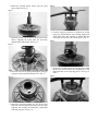
Form No. 0453-851 Arctic Cat® Wildcat Installation Instructions - Service Parts Wildcat Clutch Kit (p/n 1436-812) NOTE: Read these Installation Instructions thoroughly before beginning the installation process. Retain these Installation Instructions for future reference. Application: All 2012-2013 Wildcat models excluding models with the Team Rapid Response Clutches. Kit includes: p/n QTY DESCRIPTION 0823-164 0823-167 0823-170 0823-271 0823-295 0823-298 0823-303 0823-348 0823-358 0823-359 0823-360 0823-372 0823-377 0823-379 0823-380 0823-382 0453-851 19 Gram Roller (Red) 21 Gram Roller (Blue) 23.5 Gram Roller (Green) Spacer (91) 28 Gram Roller (Grey) 33.25 Gram Roller (Black) Driven Clutch Spring Driven Clutch Spring Spacer (90) Spacer (92) Spacer (93) 24 Gram Roller Driven Clutch Spring Driven Clutch Spring 45° Driven Clutch Cam 35° Driven Clutch Cam Instructions 8 8 8 1 8 8 1 1 1 1 1 8 1 1 1 1 1 NOTE: To remove the drive clutch and driven pulley from the vehicle, refer to the appropriate model year Wildcat Service Manual. DISASSEMBLING DRIVE CLUTCH 1. Remove the cap screws securing the CVT cover; then using a rubber mallet, gently tap on the cover tabs to loosen the cover. Account for a gasket and two alignment pins. 2. Remove the nut securing the movable drive face; then remove the face. Account for a spacer and a flat washer. 3. Remove the movable drive face plate; then remove and retain existing rollers. 4. Install new desired Rollers. ATV-1152A DISASSEMBLING DRIVEN CLUTCH NOTE: For this procedure, Clutch Spring Compressor Kit (p/n 0444-272) is required. NOTE: To remove the drive clutch and driven pulley from the vehicle, refer to the appropriate model year Wildcat Service Manual. ! WARNING The clutch assemblies are under extreme spring pressure, and only experienced technicians using the proper tools should perform service on these components. Failure to follow proper procedures could result in serious injury or death. Always wear safety glasses and observe proper shop techniques. Keep bystanders clear of work area at all times. 1. Secure the clutch spring compressor base in a work vise attached to a stable work table or work bench.See Fig. 1. ! WARNING Use only a spring compressor tool base with a screw length of 14” or greater or serious injury could occur. GZ074 Fig. 1 Fig. 4 WC422A 2. Place the driven pulley assembly onto the base; then note the location of the spring anchors in the movable sheave and cam and mark them for assembly purposes. See Fig. 2 and 3. WC418A 4. Turn the wing nut counterclockwise to relax the spring. As the cam clears the key in the fixed driven shaft, there will be a slight clockwise rotation of the cam. This is normal due to spring preload. ! WARNING Fig. 2 If at anytime the cam hangs up or the tool feels slack and the spring is not completely extended, stop and determine the cause. Failure to do so could result in the driven pulley assembly suddenly coming apart and severe injury or death could occur. 5. Completely relax the spring until all pressure is removed from the compression yoke; then remove the wing nut, compression yoke, snap ring, and centering bushing. 6. Remove the cam and spring; then remove the movable driven sheave. Account for a square key. WC753 7. Remove the fixed driven sheave from the compression tool base. Fig. 3 INSPECTING 1. Inspect the sheave faces for cracks, grooving, or “checking”. See Fig. 5 and 6. Fig. 5 WC391A 3. With the centering bushing, compression yoke, and wing nut in place, tighten the wing nut sufficiently to relax pressure on the snap ring and remove the snap ring. See Fig. 4. WC381 Fig. 6 Fig. 9 WC383 WC383A 2. Inspect the cam shoes on the movable driven sheave for chipping, excessive scoring, or general condition. See Fig. 7. 6. Inspect the spring for kinks by rolling on a flat surface. The spring should roll freely with no eccentricities. 7. Inspect spring ends and spring anchors in cam and movable driven sheave for wear or enlarged spring anchor holes. Fig. 7 NOTE: If any of the components fail the above inspection, the driven pulley must be replaced. CALIBRATING WC384A NOTE: Always replace the cam shoes as a complete set. 3. Inspect the cam ramp faces for galling, scoring, or excessive wear. See Fig. 8. Fig. 8 NOTE: The Wildcat ROV was designed for the average rider under average operating conditions. Because actual operating conditions may differ from rider to rider, a variety of clutching calibration components is available. Please see the attached clutching calibration sheet at the end of these instructions. ASSEMBLING ! WARNING The clutch assemblies are under extreme spring pressure, and only experienced technicians using the proper tools should perform service on these components. Failure to follow proper procedures could result in serious injury or death. Always wear safety glasses and observe proper shop techniques. Keep bystanders clear of work area at all times. 1. Clamp the Clutch Spring Compressor in a suitable work vise; then set the fixed driven sheave on the base. See Fig. 10. Fig. 10 WC382 4. Inspect the key and key ways in the cam and fixed driven sheave for excessive wear. 5. Inspect the wear bushings in the movable driven sheave for wear or loose fit in the sheave. Replace as a set. See Fig. 9. WC387 2. Install the movable driven sheave onto the fixed sheave shaft. See Fig. 11. Fig. 14 Fig. 11 WC414 WC388 3. Install the spring over the hub of the movable driven sheave engaging the spring into the previously marked spring anchor hole. See Fig. 12. 6. Turn the wing nut clockwise to compress the spring being very careful that the cam correctly engages the fixed driven hub; then continue to tighten until the cam ramps are just above the cam shoes. See Fig. 15. Fig. 15 Fig. 12 WC398 WC391A 4. Place the cam over the spring and align the spring tip to the previously marked anchor hole. See Fig. 13. 7. Rotate the moveable sheave and cam together to align the keyway; then install the key making sure it fits flush and clear of the snap ring groove. See Fig. 16 and 17. Fig. 16 Fig. 13 WC753 5. Install the centering bushing into the fixed driven hub; then with the sharp side upward, place the snap ring onto the assembly and install the compression yoke and wing nut. See Fig. 14. WC411A Fig. 17 Fig. 18 WC412 WC419 8. Rotate the moveable sheave clockwise to the correct side of the cam ramp; then tighten with a wingnut to compress the cam to clear the snap ring groove. Install the snap ring making sure it is seated properly. See Fig. 18. 9. Using the snap ring tool, spin the snap ring in the groove to ensure it is securely seated. Turn the wing nut counterclockwise slowly allowing the cam to contact the snap ring and relieve pressure. 10. Remove the wing nut, compression yoke, and centering bushing; then remove the driven pulley assembly from the clutch spring compressor. NOTE: To install the drive clutch and driven pulley, refer to the appropriate model year Wildcat Service Manual. Printed in the U.S.A. ®™Trademarks of Arctic Cat Inc., Thief River Falls, MN 56701 0213