1
GAS ANALYZER
Mod. INFRAGAS-291 / HF
SERVICE
MANUAL
Edition: May 1998. Vers. 1.19
ASSEMBLAD - Technical office - Automotive Division
Master file: pc-c:\winword\dm94\291\R291gb12.doc
GB
Infragas-291 / HF service manual
INDEX
1
1.1
1.2
1.3
1.4
1.5
1.6
1.7
DESCRIPTION
General specifications
Keyboard
Display and lamps
Printer
Standard accessories
Rear panel
Optional accessories
page
"
"
"
"
"
"
"
4
4
5
6
8
8
9
9
2
2.1
2.2
2.3
2.4
2.5
DESCRIPTION OF OPERATIONS
Installation procedure
Powering up the instrument
Use of the instrument
Calibration using gas bottle
Oxygen transducer replacement
page
"
"
"
"
"
10
10
10
10
11
11
3
3.1
3.2
PERFORMING A TEST
Standard test
Cares and notes
page 12
"
12
"
14
4
REAL-TIME CLOCK SETUP
page 16
5
5.1
5.2
5.3
5.4
5.5
5.6
5.7
5.8
5.9
5.10
5.11
5.12
5.13
5.14
5.15
STANDARD GAS CALIBRATION
Periodic maintenance utility program
P.E.F. factor setting
Factory setting data display
Workshop customization
Customization data display
Calibration bottle certified data
Current concentration of bottle
Date & time setting
Current analyzer date & time display
Automatic gas calibration procedure
Temperature and pressure calibration
Reinitialize the analyzer
Analog channels voltage levels
Warm reset
Back to dos
page
"
"
"
"
"
"
"
"
"
"
"
"
"
"
"
6
6-1
6-1-1
6-1-2
OPERATION AVAILABLE FROM KEYBOARD page 23
Function enabling/disabling using keyboard
“
23
Skip Warm-up phase
“
23 <== (###)
Removing customization from the printer test report “
23 <== (###)
ASSEMBLAD S.r.l. - Costruzioni Elettroniche
Via Marzabotto, 4 - 50013 Campi Bisenzio - Florence - Italy
Tel. +39-55-890485 - Fax +39-55-890496
17
17
18 <==
18
19
19
19 <==
19
19
19
20 <==
21 <==
21 <==
21
22
22
(###)
(###)
(###)
(###)
(###)
2
Infragas-291 / HF service manual
6-1-3
6-2
6-2-1
6-2-2
Modifying P.E.F. value
Normal operation (routine)
Updating the clock/Calendar
Select the right fuel
6-3 Gas calibration using keyboard
6-3-1 Calibration from keyboard using Gas Bottle
“
“
“
“
23 <== (###)
24
24
24
“
“
24 <== (###)
25 <== (###)
7
TECHNICAL DATA
page 26
8
TROUBLESHOOTING
page 28
9
RESIDUAL HC TEST
page 33
10
AIRTIGHT SEAL TEST
page 33
(*) = OPTIONAL
Note: (###) the meaning of this mark it’s: OPERATION ACCESSIBLE AT THE
AUTHORIZED SERVICE ONLY and it’s necessary to know the Password to entry. This
operations are described in the Service Manual only.
Password: GHZGCR
ASSEMBLAD S.r.l. - Costruzioni Elettroniche
Via Marzabotto, 4 - 50013 Campi Bisenzio - Florence - Italy
Tel. +39-55-890485 - Fax +39-55-890496
3
Infragas-291 / HF service manual
1 DESCRIPTION
Infragas 291 is a self-calibrating, multifunctional infrared exhaust gas analyzer, with
microprocessor based electronic circuitry.
1.1 GENERAL SPECIFICATIONS
1)
CO, CO2 and HC measurements based upon a NDIR method. HC range is 5000 ppm
wide, in order to allow a quantitative evaluation of the performance of each cylinder. A
"corrected" value of CO (see Chapter 3) is available on the print out.
2)
O2 measurement (*) performed using an electrochemical transducer provided on the
rear panel of the instrument.
3)
RPM measurement performed using the RPM Inductive Probe to be connected with
one of the cylinders and has a 2/4 stroke selection.
4)
Ambient Pressure measurement (PRESS mb) based upon a specific pressure
transducer provided inside the instrument.
5)
Ambient (AMB °C) and Oil Temperature (OIL °C) measurements performed using 2
separate temperature transducers provided one in the temperature probe (*) and the
other inside the instrument.
6)
Lambda and Air Fuel Ratio (AFR) computations obtained from gas measurement to
test car manufacturer spec's (see Chapter 3).
7)
Real-Time Clock-Calendar with battery backup allowing a data retention period of 5
days (guaranteed). A special function is provided to update the Real-Time Clock (see
Chapter 4).
8)
Automatic Condensate Drainage with massage on display and automatic stop of gas
suction. However, condensate may be manually emptied by depressing the drainage
valve pushbutton below the condensate filter.
9)
Green high-efficiency LED display to improve brightness.
10) 24 column Impact Printer to report all data measured ( both displayed or not). Printed
repord may also be customized (*) with the Workshop Data.
11) Functional 5-keys Membrane Keypad for a good protection against dust and oil. Two
red LED lamps monitor power on (ON) and pump on (PUMP).
12) Green high-efficiency LED lamps to monitor 4S / 2S selection, measurement selected
on the FUNCTION display, power on and pump on. Besides, power on led blinks in
case of voltage supply out of limits provided (220 Vac +/- 15 %).
ASSEMBLAD S.r.l. - Costruzioni Elettroniche
Via Marzabotto, 4 - 50013 Campi Bisenzio - Florence - Italy
Tel. +39-55-890485 - Fax +39-55-890496
4
Infragas-291 / HF service manual
13) Gas filtering devices (condensate filter and particle filter) provided externally on the
rear panel for a quick maintenance.
14) Error and Special Operating condition messages on display to signal the occurrency
of situations like flow missing (Err1) and condensate drainage (Con).
15) Self-calibration feature (using MEAS key) with "Cal" message on display and
automatic switch to gas suction at the end of this stage. Self-calibration does not
require removal of the hose from car exhaust pipe.
16) Standard RS-232 Serial Interface for future expansions for data processing
equipments and for other external equipments.
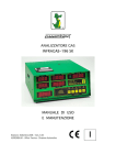
1.2 KEYBOARD
Infragas 291 keyboard is composed of 5 keys each corresponding to a specific function.
1)
MEAS (MEASURE) key : causes the instrument to start a new measurement by
initially performing a self-calibration stage. At the beginning the instrument switches
its internal valve to suck in ambient air. This stage requires approx. 30 sec. during
which the message "Cal" appears on CO and CO2 displays and data on gas displays
(including HC and O2) have no meaning. During this stage a new push of MEAS key
causes a termination of measurement sequence. At the end of self-calibration stage
the message "Cal" disappears and instrument automatically switches to suck in gases
from the hose, thus keeping the suction pump on until the START / STOP key has
been pressed or after about 10 minutes from this operation.
2)
START / STOP key: causes the suction pump to switch off. Pump state is displayed
by the pump lamp placed beside the key. For restart the Pump is necessary to push
the MEAS key.
3)
4S / 2S key: allows selection of RPM computation mode, related to the engine type
(4-stroke or 2-stroke); the lighting of one of the two lamps placed beside RPM display
indicates selection made (see also Cap. 6-2-2 for motor fuel selections).
4)
FUNC key: allows selection of measurement to be displayed on FUNCTION display.
Available measurements are:
-
Engine Oil Temperature (OIL °C)
Ambient Temperature (AMB °C) the value displayed show the inside temperature
Ambient Pressure (PRESS mb)
Lambda value for many motor fuel (blinking O2 led and "L" on the rightmost digit)
Air / Fuel Ratio (blinking O2 led and "A" on the rightmost digit)
Each push of the FUNC key causes a switching of selection from top to bottom as
indicated by the corresponding lamp placed beside.
ASSEMBLAD S.r.l. - Costruzioni Elettroniche
Via Marzabotto, 4 - 50013 Campi Bisenzio - Florence - Italy
Tel. +39-55-890485 - Fax +39-55-890496
5
Infragas-291 / HF service manual
Regardless of selection made on FUNCTION display, a printing will include every
measurement performed by the instrument, even if not displayed.
5)
PRINT key: performs the print out of all measured and / or computed data (both
displayed or not) together with date and time and Workshop data (*) if provided.
Lambda value is relative to different propellant. A CO corr. parameter (corrected CO
value) is also printed (see Chapter 3).
If you need to have another report you must repeat the sequences: START/STOP
MEAS and after “Cal” time
PRINT when the display has a stable appearance.
1.3 DISPLAY AND LAMPS
INFRAGAS-291 / HF has on the front panel 5 displays and 6 led lamps; displays are
splitted into 3 sets.
1)
2)
Infrared bench related displays : CO, CO2 and HC displays. This set is placed on the
right upmost part of the panel; it constantly shows measured data except:
-
during warm-up time the CO display show the PEF value, CO2 show the writing
“PEF”, and the Function display show the Warm-up time remaning in minutes.
-
during self-calibration stage CO and CO2 displays have the "Cal" message on,
while gas data (including HC and O2) are meaningless.
-
in case of an insufficient flow on gas path occurs, on CO CO2 and HC displays
the message “Err1” appears. In this conditions gas measurement is inhibited.
-
in case of condensate excess, on CO and CO2 displays the message "Con"
appears indicating that instrument has stopped suction and provides for automatic
drainage. During this stage gas measurement is inhibited.
Auxiliary parameters displays; this set, placed on the left upmost part of the front
panel, includes:
-
RPM display and 4S / 2S lamps indicating selection made by 4S / 2S key. RPM
display continuously shows engine RPM whichever are instrument operating
conditions ( see also Cap. 6-2-2).
ASSEMBLAD S.r.l. - Costruzioni Elettroniche
Via Marzabotto, 4 - 50013 Campi Bisenzio - Florence - Italy
Tel. +39-55-890485 - Fax +39-55-890496
6
Infragas-291 / HF service manual
3)
Auxiliary parameters displays; this set, placed on the left downmost part of the front
panel, includes FUNCTION display and four selection lamps on the left showing one
of the six available parameters selectable by FUNC key:
-
Engine Oil Temperature
Ambient Temperature
Ambient Pressure
Oxygen Concentration
Lambda value
Air / Fuel Ratio
FUNCTION display always shows the selected measure except in the following
cases:
-
O2 measurement: while self-calibrating ("Cal" message on CO and CO2 displays)
or condensate draining ("Con" message on CO and CO2 displays) function data
are meaningless;
-
for every selection: in case of missing flow in pneumatic circuitry, FUNCTION
display shows the "Err1" message and gas data are meaningless.
ASSEMBLAD S.r.l. - Costruzioni Elettroniche
Via Marzabotto, 4 - 50013 Campi Bisenzio - Florence - Italy
Tel. +39-55-890485 - Fax +39-55-890496
7
Infragas-291 / HF service manual
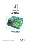
1.4 PRINTER
The instrument is equipped with a 24 column impact printer. Both paper roll and ink-ribbon
cartridge are of easy and quick replacement, being accessible from the door provided on
the front panel of the instrument.
Printer reports, whenever required, all the available paramenters together with data and
time and Workshop data (*) if provided. Whatever may be selected on FUNCTION
display, all the auxiliary parameters are printed out.
Note
After one print report it is always necessary to perform a calibration pressing
START/STOP key then MEAS key before to request another operation of PRINT.
Press to remove printer ribbon
Press to advance paper
1.5 STANDARD ACCESSORIES
1)
2)
3)
4)
5,80 m. hose with gas takeup tip.
RPM probe.
Line power cord.
This manual.
ASSEMBLAD S.r.l. - Costruzioni Elettroniche
Via Marzabotto, 4 - 50013 Campi Bisenzio - Florence - Italy
Tel. +39-55-890485 - Fax +39-55-890496
8
Infragas-291 / HF service manual
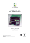
1.6 REAR PANEL
On INFRAGAS-291 / HF rear panel the following devices are displaced:
1)
2)
3)
4)
5)
6)
7)
8)
9)
10)
11)
Power supply socket and switch with fuse holder.
RPM probe connector.
Temperature probe connector.
Standard RS-232 serial interface connector.
Gas outlet.
Condensate filter with gas inlet junction and a connection to the drainage valve.
Particles filter.
Oxygen transducer holder with cover (*).
Drainage valve.
Identification plate.
Drainage pipe
1.7 OPTIONAL ACCESSORIES
1)
2)
3)
4)
5)
Oil Temperature probe.
Infrared remote control.
Trolley.
Personalized print out (see Cap. 5-4 Workshop customization)
Oxygen transducer (for INFRAGAS-291 / HF which has not that sensor but it is
possible to install it later. When Oxygen trasducer it is installed or replaced you must
have gas calibration).
ASSEMBLAD S.r.l. - Costruzioni Elettroniche
Via Marzabotto, 4 - 50013 Campi Bisenzio - Florence - Italy
Tel. +39-55-890485 - Fax +39-55-890496
9
Infragas-291 / HF service manual
2
DESCRIPTION OF OPERATIONS
2.1 INSTALLATION PROCEDURE
Remove the instruments from its package, install it on a trolley and connect accessories
as follows:
-
connect RPM inductive probe to the RPM connector placed on rear panel;
-
connect gas hose to the gas takeup tip being sure that the arrow on the filter
placed on the hose is in the direction of gas flow, then connect the other side of
the hose to the condensate filter on rear panel;
- connect temperature probe (*), if provided, to the rear panel connector;
Leave accessories always connected to the instrument, even if not used, to speed up
operations.
Warning:
once unpacked, the instrument may have internal NiCd battery discharged; this means
that real-time clock has no date / time or a date / time value incorrect. In this case the
instrument must be connected to power and left powered on continuously for 24 hours to
insure full charge to internal NiCd battery. Then follow instructions to setup real-time clock
(see Chapter 4).
2.2 POWERING UP THE INSTRUMENTS
Connect the line power cord to the instrument and switch it on; the instrument starts
printing the preamble. Wait for 15 min. (15 min it is the max. time) of warm-up time before
to start measurements on gases. The “Function” display show the warm-up time
remaining.
Warm-up procedure doesn’t stop until the analyzer reach the requested temperature.
After this procedure the analyzer automatically performs a self-calibration then it will pass
to the exhaustion stage.
2.3 USE OF THE INSTRUMENT
1)
After switching on, the instrument automatically sets to the following conditions:
-
4-stroke engine type (RPM selection)
During the “Cal” procedure you can select the engine fuel (see 6--2-2)
O2 display (FUNCTION selection)
ASSEMBLAD S.r.l. - Costruzioni Elettroniche
Via Marzabotto, 4 - 50013 Campi Bisenzio - Florence - Italy
Tel. +39-55-890485 - Fax +39-55-890496
10
Infragas-291 / HF service manual
2)
Insert takeup tip into the motorcar exhaust pipe, connect RPM probe to one of the
spark plugs cables and insert the temperature probe, if provided, into the oil
measuring rod receptacle.
3)
After warm-up, instrument is ready to work; user may select, using FUNC key, one of
the auxiliary parameters available on FUNCTION display; moreover the engine type
may be selected using 4S / 2S key for RPM measurement.
4)
For gas measurement user presses MEAS key causing a self-calibration, after which
analyzer passes to a gas exhaustion stage. During this period the instrument, if gas is
present, periodically performs calibrating procedures (every 10 min.), while
automatically turns the pump off in case of gas lack for at least 10 min.
5)
Operator may decide everytime to print out data using PRINT key, provided that
pump is on.
6)
Once measurement has been completed, or whenever the operator wants, he may
decide to terminate gas exhaustion pressing START / STOP key. However, if no
action is taken the instrument automatically turns the pump off after approx. 10 min.
of continuous operation, to preserve the pump from an useless stress.
2.4 CALIBRATION USING GAS BOTTLE
Manufacturer recommends a calibration with certified gas bottle (see Chapter 5) every six
months. In some countries legislation defines specific rules. Please contact our distributor
for this periodical service activity.
2.5 OXYGEN TRANSDUCER REPLACEMENT
The oxygen transducer (*) life-time is 12 months (minimum) from the date of delivery.
Please contact our distributor for periodical replacement
ASSEMBLAD S.r.l. - Costruzioni Elettroniche
Via Marzabotto, 4 - 50013 Campi Bisenzio - Florence - Italy
Tel. +39-55-890485 - Fax +39-55-890496
11
Infragas-291 / HF service manual
3
PERFORMING A TEST
3.1 STANDARD TEST
Here the suggested procedure to test an engine is explained. It is also shown that
INFRAGAS-291 / HF is a complete instrument to test in an exhaustive way the combustion
process and all the related devices of a car engine.
A)
Install and switch on the instrument as explained in the preceding chapters.
B)
Insert the gas takeup tip into the exhaust pipe.
C)
Start the car engine and connect the RPM probe to one of the spark plugs cables,
being sure that the arrow on the body of the clamp is in the direction of cylinder. Then
select the engine type using 4S / 2S key.
D)
Insert the temperature probe into the oil rod receptacle.
E)
Using FUNC key select ambient temperature (AMB °C) and verify that its value is in
the range 5÷40 °C.
F)
Using FUNC key select ambient pressure (PRESS mb) and verify that its value is in
the range 850÷1050 mbar.
G) Using FUNC key select oil temperature and wait until this parameter has reached 80
°C to be sure that engine has been properly warmed up. In case of lower temperature
keep the engine at about 2000 RPM until this temperature is reached.
H)
When the proper oil temperature has been reached verify that RPM value is in the
range declared by the car manufacturer. In case of missing declaration RPM must not
exceed 1000 RPM.
I)
If the 15 min. warm-up time is over, and Pump is OFF, press MEAS key and start
sampling exhaust gases (after a preliminary automatic self-calibration) until gas
readings are stable.
J)
Print data as a report of measurements done. Note that printer gives an additional
parameter: the corrected value of CO (CO corr). This paramenter is helpful in case of
leaks in the car exhaust pipe. Expression for CO corr is the following:
[CO] corr % = (#) x
[CO%] / ( [CO%]+[CO2%] )
where (#) it is:
= 15 for engines supplied with gasoline
= 12 for engines supplied with CH4
= 14 for engines supplied with GPL
if CO+CO2 is lower to 15, otherwise CO corr = CO
ASSEMBLAD S.r.l. - Costruzioni Elettroniche
Via Marzabotto, 4 - 50013 Campi Bisenzio - Florence - Italy
Tel. +39-55-890485 - Fax +39-55-890496
12
Infragas-291 / HF service manual
K)
Compare following data with the corresponding ones declared by the car
manufacturer, or with expected values:
-
CO
CO2
HC
O2
Lambda
AFR
AFR (Air Fuel Ratio) is a parameter computed by INFRAGAS-291 / HF software.
Lambda is a parameter computed as follows:
Lambda = Num / Den
where:
Num:
21 x [ [CO2] + ([CO]/2) + [O2] + ((HCV/4) x 3,5 / (3,5 + [CO] / [CO2]) - 0.00877 x ([CO2] + [CO]) ]
Den:
[21+0.5628 x ( ([CO]/[CO2]) / 3,5+([CO] / [CO2]) ) ]x[ 1+HCV/4 - 0,01754/2] x [CO2]+[CO]+[HC] x 6 x 10 -4 ]
where HCV = 1.85 for engine supplyed with Gasoline
= 2.57 for engine supplyed with GPL
= 4
for engine supplyed with Methane
With [CO], [CO2] e [O2] = % in vol.
and HC = ppm in vol.
If out of range data are measured, proceed with proper repairs and adjustments on
the motorcar.
L)
After this work, print a report of repairs and adjustments done.
ASSEMBLAD S.r.l. - Costruzioni Elettroniche
Via Marzabotto, 4 - 50013 Campi Bisenzio - Florence - Italy
Tel. +39-55-890485 - Fax +39-55-890496
13
Infragas-291 / HF service manual
3.2 CARES AND NOTES
-
During tests be sure that RPM probe cord is not passing close to the other
cylinders or to the coil to avoid electronic noises.
-
Be sure that arrow on the clamp of RPM probe is in the right direction (to the
cylinder).
-
Sometimes RPM probe cannot measure RPM. It depends on very special kind of
plug cords strongly shielded. In such cases write manually RPM on printed report
as read from the engine speed indicator.
-
Before every test, verify that condensate filter is not full of water to avoid an
unpredictable stop of the test itself for a possible automatic condensate drainage.
Press the drainage valve white button to manually empty the condensate filter.
-
The internal porous septum of condensate filter must be cleaned periodically to
avoid flow missing. To do this first be sure that pump is off, then remove the small
silicone hose from the drainage valve pinchcock and unscrew carefully but firmly
the plastic glass of filter; the internal septum can be removed by acting on the
screw placed below it. The porous septum can be cleaned by bathing it with
gasoline or trichloroethylene. After a while, blow in compressed air and put it back
in its place. Finally screw the plastic glass, being sure that the o-ring is well
positioned, and put the small silicone hose in the valve pinchcock.
-
Replace periodically the particle filter.
-
If the "Err1" message appears on FUNCTION display verify that:
- the gas tip and the hose are not blocked up or full of condensate;
- the condensate filter is not full;
- the particle filter is not damaged or blocked up;
- the gas exhaust of instrument is not blocked up. Note that in this case, after
having removed the block, it takes about 5 min. to restore O2 measurement
stability because of possible pneumatic stress of Oxygen sensor.
-
It is advisable to remove, almost every day, water from gas hose by blowing in
compressed air in the direction of particle filter arrow (from the tip to the
instrument) obviously after having removed the hose from the instrument.
-
When oil temperature is below 45 °C the "or" message (out of range) is displayed
on FUNCTION display, if oil temp. is selected.
-
The "or" message may also appear when Lambda and AFR are selected on
FUNCTION display. It means that these parameters are out of range (see ranges
in Chapter 6).
ASSEMBLAD S.r.l. - Costruzioni Elettroniche
Via Marzabotto, 4 - 50013 Campi Bisenzio - Florence - Italy
Tel. +39-55-890485 - Fax +39-55-890496
14
Infragas-291 / HF service manual
-
When ambient temperature is below 0 °C or above 45 °C the "or" message is
displayed on FUNCTION display if amb. temp. is selected.
-
When date / time values are not correct (out of range), date and time are not
printed by the instrument. A date / time setup procedure must be performed (see
Chapter 4).
-
When date / time values are lost due to power absence for a long period, perform
setup procedure and then keep instrument on for at least 24 hours to completely
charge internal NiCd battery.
-
The "ON" led on front panel blinks when power supply is out of its range (+ 10, 15 %).
ASSEMBLAD S.r.l. - Costruzioni Elettroniche
Via Marzabotto, 4 - 50013 Campi Bisenzio - Florence - Italy
Tel. +39-55-890485 - Fax +39-55-890496
15
Infragas-291 / HF service manual
4
REAL-TIME CLOCK SETUP (Manual adj)
This procedure is useful everytime a wrong date / time is printed due to a long period of
power absence (more than 5 days).
Wrong data from real-time clock can be detected in the preamble after switching on.
1) Press FUNC key and PRINT key simultaneously. The instrument will display the
"GiO" message on CO2 display (day setting) and a 2 digit number on CO display,
indicating currently stored day. Act on 4S / 2S and PRINT keys respectively to
increase and decrease current day value and then press FUNC key.
2) The instrument now shows the "MES" message on CO2 display (month setting)
and a 2 digit number on CO display, indicating currently stored month. Act on 4S /
2S, PRINT and FUNC keys as described above.
3) The instrument now shows the "Ann" message on CO2 display (year setting) and
a 2 digit number on CO display, indicating currently stored year. Act on 4S / 2S,
PRINT and FUNC keys as described above.
4) The instrument now shows the "orE" message on CO2 display (hour setting) and
a 2 digit number on CO display, indicating currently stored hour. Act on 4S / 2S,
PRINT and FUNC keys as described above.
5) The instrument now shows the "Min" message on CO2 display (minute setting)
and a 2 digit number on CO display, indicating currently stored minute. Act on 4S /
2S, PRINT and FUNC keys as described above.
After minutes setup, FUNC key pressure causes real-time clock setup termination and a
return to normal run.
ASSEMBLAD S.r.l. - Costruzioni Elettroniche
Via Marzabotto, 4 - 50013 Campi Bisenzio - Florence - Italy
Tel. +39-55-890485 - Fax +39-55-890496
16
Infragas-291 / HF service manual
5
STANDARD GAS CALIBRATION
5.1 PERIODIC MAINTENANCE UTILITY PROGRAM
Some of the operations available on INFRAGAS-291 / HF are feasible from keyboard or
remotely using a Personal Computer connected to the analyzer with a proper serial link
wiring.
Other functions are instead possible only with a remote control, activating the "Periodic
Maintenance Utility" program.
This program can be installed creating a directory named A291 on hard disk and then
copying in it all the contents of the distributed floppy disk.
It is also possible to execute an automatic installation inserting the distributed floppy disk
in its drive and keying in:
A:\INSTALL <enter>
or C: md A291 <enter> and Copy a:*.* C:\A291 <enter>
After the installation it is possible to start the program going under the directory named
A291 and then keying in:
A291 <enter>
An image described ahead and representing a choice menu will appear.
In the upper right part of the screen current date and time are displayed while in the
middle the available functions can be selected using arrow keys (in the last line a brief
description of currently selected option will appear).
Serial port configuration is performed pressing <F6> key and then a window allowing serial
communication parameters insertion will be displayed.
INFRAGAS-291 / HF default setting is:
Speed : 1200 Baud
Bit :
8
Parity : None
Now each selectable menu option will be explained.
Note: (###) the meaning of this mark it’s: OPERATION ACCESSIBLE AT THE
AUTHORIZED SERVICE ONLY and it’s necessary to know the Password to entry. This
operations are described in the Service Manual only.
ASSEMBLAD S.r.l. - Costruzioni Elettroniche
Via Marzabotto, 4 - 50013 Campi Bisenzio - Florence - Italy
Tel. +39-55-890485 - Fax +39-55-890496
17
Infragas-291 / HF service manual
5.2 P.E.F. FACTOR SETTING (###)
It is used to modify current P.E.F. (Propan/Hexane Factor).
It must be used only in the eventuality of a loss (for any reason) of the one recorded in
factory during test. This situation would in fact cause errors in reading HC values.
Current P.E.F. is visible on CO display after INFRAGAS-291 / HF switching on.
After selection of this option a window asking for the input of a 3-digit number
(representing new P.E.F. value x 1000) will appear.
5.3 FACTORY SETTING DATA DISPLAY
After the choice of this option factory data recorded in INFRAGAS-291 / HF are displayed
in the following way:
- Serial number
- P.E.F.
- Version and firmware release
ASSEMBLAD S.r.l. - Costruzioni Elettroniche
Via Marzabotto, 4 - 50013 Campi Bisenzio - Florence - Italy
Tel. +39-55-890485 - Fax +39-55-890496
18
Infragas-291 / HF service manual
5.4 WORKSHOP CUSTOMIZATION
This option allows INFRAGAS-291 / HF customization input.
Customization consists of 6 text lines (24 characters each) that will be printed on every
ticket.
5.5 CUSTOMIZATION DATA DISPLAYING
This option allows INFRAGAS-291 / HF current customization display.
5.6 CALIBRATION BOTTLE CERTIFIED DATA (###)
Selection of this function allows transmission to INFRAGAS-291 / HF of certified bottle gas
volumetric concentrations to be used for periodic gas calibration of the instrument.
Volumetric concentrations of CO e CO2 must be input in % while those of HC (Propan)
and Hexane in ppm (parts per million).
Hexane percentage, even if present, isn't used in gas calibration, so it is advisable to input
the default value of 1000.
5.7 CURRENT CONCENTRATION OF BOTTLE
Selection of this option causes display of INFRAGAS-291 / HF recorded data relative to
certified bottle gas volumetric concentrations. Analyzer will use these parameters during
gas calibration procedure.
5.8 DATE & TIME SETTINGS
This function performs internal clock setting using Personal Computer current date and
time, which are displayed in the upper right part of the screen with a green background.
5.9 CURRENT ANALYZER DATE & TIME DISPLAY
Choosing this option, INFRAGAS-291 / HF current date and time will be displayed on a
screen window.
ASSEMBLAD S.r.l. - Costruzioni Elettroniche
Via Marzabotto, 4 - 50013 Campi Bisenzio - Florence - Italy
Tel. +39-55-890485 - Fax +39-55-890496
19
Infragas-291 / HF service manual
5.10 AUTOMATIC GAS CALIBRATION PROCEDURE (###)
Selection of this option will start instrument automatic gas calibration procedure.
Preliminary stage is performed connecting reference bottle with INFRAGAS-291 / HF
exhausted gases input valve by means of a flexible pipe with an inside diameter of 5 mm
and not longer than 2 m.
Typically, bottle gas must be brought to the instrument with a relative pressure of 0.1 bar
and a flux of 1 litre / minute.
Bottle pressure-gauge mustn't indicate a pressure lower than 2 atm., otherwise it is
necessary to replace the bottle.
Bottle includes a test certificate on which gas concentration values are carried. Be sure
that such values are in accordance to the ones stored in INFRAGAS-291 / HF selecting
"Current concentration of bottle", otherwise they must be modified selecting "Calibration
certified bottle data".
Advised values for a good instrument setting are the following:
CO :
CO2 :
HC (Propan):
between 1.5 % and 4 %
between 9 % and 13 %
between 800 ppm e 2000 ppm
(everyone in Nitrogen).
At last, be sure that INFRAGAS-291 / HF is operative, that is having completed its initial
heating stage.
Then it is necessary to perform a zero calibration pressing <MEAS> key and after its
completion pump must be deactivated.
After these operations gas calibration can start selecting the corresponding option with
<enter> and opening bottle cock.
After a stabilization stage of gas inside analyzer (depending on pipe length and bottle
pressure, typically 20÷30 seconds) INFRAGAS-291 / HF buzzer rings to confirm selfcalibration request and then it rings again to confirm self-calibration completion.
Simultaneously, a successful message is displayed on the screen, together with the
direction of turning off and removing the bottle.
Procedure has thus come to the end.
ASSEMBLAD S.r.l. - Costruzioni Elettroniche
Via Marzabotto, 4 - 50013 Campi Bisenzio - Florence - Italy
Tel. +39-55-890485 - Fax +39-55-890496
20
Infragas-291 / HF service manual
5.11 TEMPERATURE AND PRESSURE CALIBRATION (###)
This option allows calibration of barometric pressure and temperature internal sensors.
Sensors are calibrated during factory test so this operation is necessary only in case of
replacement of one of them.
In order to perform this operation standard thermometer and barometer are necessary and
their values will have to be input in the screen window appeared after selection of this
option.
Standard thermometer must take temperature under stationary conditions, as close as
possible to INFRAGAS-291 / HF temperature sensors.
5.12 REINITIALIZE THE ANALYZER (###)
This option must be used with care and only in case of absolute necessity because it
implies INFRAGAS-291 / HF recorded data deletion and their replacement with the ones
given by the manufacturer and recorded during factory test.
This option is necessary only when INFRAGAS-291 / HF shows a completely wrong
behaviour or after replacement of some critical electronic components.
Because of the risks of this operations, before its execution it is necessary to input the
password "ASSEMBLAD". After, a window with instrument serial number will be displayed.
If there is more than one serial number it is possible to select the one of the instrument to
be reinitialized using arrow keys and then pressing <enter>.
After a few seconds the operation will be completed and a confirmation message will be
displayed.
Changes made will be manifest switching off and then on again INFRAGAS-291 / HF or
simply selecting "Warm reset" option.
5.13 ANALOG CHANNELS VOLTAGE LEVEL
Selection of this option causes voltage display of all the analog channels in order to
perform channels gain calibration.
This operation has already been executed in factory so it is necessary only after
replacement of some critical electronic components.
Measurements are displayed in Volts and updated every second.
ASSEMBLAD S.r.l. - Costruzioni Elettroniche
Via Marzabotto, 4 - 50013 Campi Bisenzio - Florence - Italy
Tel. +39-55-890485 - Fax +39-55-890496
21
Infragas-291 / HF service manual
5.14 WARM RESET
This option performs INFRAGAS-291 / HF restart, like switching off and then on again the
instrument, but without doing it.
After that INFRAGAS-291 / HF starts its heating initial stage, which will end quickly
because in the meanwhile infrared emission hasn't been stopped.
5.15 BACK TO DOS
It allows program ending and the return to the operating system.
ASSEMBLAD S.r.l. - Costruzioni Elettroniche
Via Marzabotto, 4 - 50013 Campi Bisenzio - Florence - Italy
Tel. +39-55-890485 - Fax +39-55-890496
22
Infragas-291 / HF service manual
6
OPERATION AVAILABLE FROM KEYBOARD
Some the operations of service on INFRAGAS-291 / HF are feasible from Keyboard
6-1 FUNCTION ENABLING/DISABLING USING KEYBOARD
6-1-1 SKIP WARM-UP PHASE (###)
In order to skip the powering up initial 15 minutes of heating press simultaneously the
PRINT+4S/2S keys within 3 seconds after powering up.
The count down display goes to ‘0’ then after few seconds the analyzer starts its normal
cycle performing an electrical calibration.
Use this option with care because subsequent gas reading could be unreliable if the
camera was not working at its normal temperature.
Remember that during the initial 15 minutes of heating, the analyzer skip this phase itself
if it found an acceptable level of thermal heating.
6-1-2 REMOVING CUSTOMIZATION FROM THE PRINTED TEST REPORT (###)
Workshop customization data can reside both in internal erasable EEPROM as in non
erasable EPROM.
If erasable data are activated (via the serial link to an external PC running the “A291”
program) they prevail over the non erasable data written in EPROM.
Pressing symultaneously FUNC + 4S/2S keys within about 10 seconds after powering up
it is possible to inhibit data residents on erasable area; in this case on the test report the
workshop customization data resident in non erasable area (EPROM) will be printed.
Such workshop customization is void (six blank line) as default.
This operation allow to restore the old customization or to change the customization data
without using a PC but replacing the EPROM with a new one supplied by ASSEMBLAD
containing new workshop customization data.
6-1-3
MODIFYING P.E.F. VALUE
(###)
The right value of P.E.F. is registered by the manufacturer during the initial testing of the
analyzer, so there’s no need to change it later unless some special test made by
specialized technical operators.
ASSEMBLAD S.r.l. - Costruzioni Elettroniche
Via Marzabotto, 4 - 50013 Campi Bisenzio - Florence - Italy
Tel. +39-55-890485 - Fax +39-55-890496
23
Infragas-291 / HF service manual
The P.E.F. value can be changed pressing simultaneously FUNC + START/STOP keys
within 10 seconds after pwering up.
6-2 NORMAL OPERATIONS
(Routine)
6-2-1 UPDATING THE CLOCK/CALENDAR
New Date & Time can be updated using an external PC running the ‘A291’ program
connected via the serial line.
If a PC can’t be used press simultaneously the FUNC + PRINT keys.
The CO2 display will show in turn Gio, Mes, Ann, Ore, Min as Day, Month, Year, Hours,
Minutes and the CO display the current setting for the value involved.
The values shown in the CO display can be changed using the key 4S/2S to increase and
the key PRINT to decrease them.
The key FUNC confirm the value shown then propose the next one in the shown CO2 list.
6-2-2
SELECT THE RIGHT FUEL
For each vehicle test the right fuel must be selected in order to evaluate the values of
LAMBDA and the CO corrected according to the existing laws.
The selection is possible during the phase of electrical autozeroing preceding each vehicle
test. In this situation the string ‘CAL’ is written on both CO and CO2 display and the RPM
display show the actual selected fuel as:
bEn0
Met0
GPL0
Cat0
= Super-premium petrol
= Methane
= Liquefied petroleum gas (LPG)
= Unleaded gasoline
Press in this phase the key 4S/2S until the right kind of fuel is shown.
The selection made is active until a new one is issued.
At the powering up the fuel selected is the default one as ‘bEn0’.
6-3 GAS CALIBRATION USING KEYBOARD
(###)
Important
The gas calibration procedure can be executed by qualified personnel by means of
external PC running the ‘A291’ program linked via the serial line.
ASSEMBLAD S.r.l. - Costruzioni Elettroniche
Via Marzabotto, 4 - 50013 Campi Bisenzio - Florence - Italy
Tel. +39-55-890485 - Fax +39-55-890496
24
Infragas-291 / HF service manual
It is also possible to activate the same procedure by the keyboard but this function is
enabled/disabled during the factory test depending on which Country the analyzer must be
used.
6-3-1
Calibration from keyboard using Gas bottle (###)
a)
Press FUNC key and MEAS key simultaneously.
The instrument will display current values of the gas concentration for
the calibration bottle and show 'bott' in the FUNCTION display.
Be sure that values shown does match exactly the values written
in the certified bottle.
If this is not the case adjust the values registered until an exact match
is performed using the FUNC key to select the digit to modify (the
blinking one) and PRINT key and 4S/2S key to increment/decrement
the selected digit.
Procedure is aborted by the START/STOP key or after 15 seconds
without any action on the keyboard.
b)
When the exact match is reached press the MEAS key to start the
calibration procedure and then open the gas bottle.
The instrument will start doing an electrical autozeroing first followed,
when the pump goes off, by the proper gas calibration emitting a first
'beep'.
If the bottle is still closed or perhaps disconnected a warning flashing
message 'bott' will appear in the FUNCTION display and the
instruments starts to emit a sustained 'beep' until the calibration is
done or the key START/STOP is depressed.
c)
the
If the calibration procedure succeeds a second 'beep' is emitted and
instrument goes back to its normal functions.
Calibration data concerning the bottle concentration remains stored inside the
instrument so, there's no need of multiple actions on the keyboard. Only two
keys are requested to performe the gas calibration if periodically the same
bottle is used.
If gas calibration is performed using single gas bottles instead of the ternary
one, the above procedure must be repeated once for each gas, putting to 0.0
the concentration values of gases each time not involved.
ASSEMBLAD S.r.l. - Costruzioni Elettroniche
Via Marzabotto, 4 - 50013 Campi Bisenzio - Florence - Italy
Tel. +39-55-890485 - Fax +39-55-890496
25
Infragas-291 / HF service manual
7
TECHNICAL DATA
Ranges of measurements and display resolution:
CO
CO2
HC
HC
O2 (*)
O2 (*)
RPM
Oil Temp. (*)
Amb. Temp. (*)
Amb. Press.
RANGE
RESOLUTION
0 ÷ 9.99 vol %
0 ÷ 19.9 vol %
0 ÷ 999 vol %
1000 ÷ 5000 ppm
0 ÷ 9,99 vol %
10 ÷ 25 vol %
400 ÷ 9000 rpm
45 ÷ 120 °C
0 ÷ 100 °C
850 ÷ 1050 mbar
0.01 %
0.1 %
1 ppm
10 ppm
0,01 %
0.1 %
10 rpm
0.1 °C
0.1 °C
1 mbar
Ranges and display resolutions of computed data:
CO corr.
AFR
Lambda
RANGE
RESOLUTION
0 ÷ 9.99 vol %
7.0 ÷ 23.0
0.50 ÷ 1.50
0.01 %
0.1
0.01
Displays and leds:
5 high efficiency green led displays.
led indicators for FUNCTION display selection.
led indicators for 4S / 2S type of engine.
Power on led indicator.
Pump on led indicator.
Keyboard:
5 functional keys keypad.
Printer:
24 column impact printer with personalizable print out.
Serial interface:
Standard RS-232 serial interface for connections with future expansions or data
processing equipments.
ASSEMBLAD S.r.l. - Costruzioni Elettroniche
Via Marzabotto, 4 - 50013 Campi Bisenzio - Florence - Italy
Tel. +39-55-890485 - Fax +39-55-890496
26
Infragas-291 / HF service manual
Other functions:
Flow missing warning message on display.
Automatic and manual condensate drainage.
Automatic self-calibration.
Voltage out of range indication.
Future developments:
The instrument has the possibility to add a further standard RS-232 serial interface.
Moreover it is possible to update software to comply with future European or local
laws.
Response time:
10 sec. (3 m sampling hose).
Warm-up time:
15 min. max.
Operating temperature:
5 ÷ 40 °C
Power supply:
220 Vac, 50 Hz with 0.5 A max absorption (110, 230, 240 Vac and/or 50, 60 Hz on
request)
Dimensions:
480 x 300 x 650 mm
Weight:
20 Kg approx.
ASSEMBLAD S.r.l. - Costruzioni Elettroniche
Via Marzabotto, 4 - 50013 Campi Bisenzio - Florence - Italy
Tel. +39-55-890485 - Fax +39-55-890496
27
Infragas-291 / HF service manual
8
TROUBLESHOOTING
Ref.
Fault
Possible Cause or Remedy
1
The analyzer does not go on.
Remove the power supply cord. Open the
door to the fuse box on the switch unit
and replace the blown fuse.
2
When powered up all the
the displays read zero and
even the printer is off.
Switch off the analyzer, remove Int. Circ.
MC146818A (RTC) from its base and
reinsert it.
3
All the displays read zero
with gas inside.
The printer only prints the
the initial message.
As above (the analyzer probably has an
old version of the program)
4
All the displays read zero.
The printer is operating
normally.
Check voltage on the three analog channels as described in the service manual.
The cause could be low infrared
emissions. If this recurs, replace the infrared
emitter and then carry out electric and gas
calibrations.
5
Some of the displays show
values close to the upper
limit of the scale, such as
CO=9.99 or CO2=19.9, etc.
Check voltage on the three analog channels as described in the service manual.
The cause could be a lack of infrared
emissions. If this recurs, replace the
infrared emitter and then carry out
electric and gas calibrations.
6.
One or more displays remain
at zero or close to the maximum value on the scale.
Check voltage on the three analog channels as described in the service manual.
The problem may be due to a broken
infrared receiver. If this recurs, replace
the infrared receiver or the entire preamp
board and then carry out electric and gas
calibrations.
7
Values of CO, CO2 and HC
shown of display are not
stable during the time.
Check, make stronger or replace the
electrical connection between the
voltage regulator LM350K (installed
dirctly on the chassis) and the screwed
wire below the chassis.
After that, check the electrical level of the
three channels (CO, CO2, HC). If needed
adjust them then recalibrate the analyzer
with the gas reference bottle.
ASSEMBLAD S.r.l. - Costruzioni Elettroniche
Via Marzabotto, 4 - 50013 Campi Bisenzio - Florence - Italy
Tel. +39-55-890485 - Fax +39-55-890496
28
Infragas-291 / HF service manual
8
the same as above.
Check if the clamp that hold the infrared
emitter is strong. If not, tighten the nuts on the
anchor plate.
After that, check the electrical level of the
three channels (CO, CO2, HC). If needed
adjust them then recalibrate the analyzer
with the gas reference bottle.
9
Oxygen levels are always
high, even in the presence
of other gases.
Check the expiry date on the sensor
(the mean life is 12 months).
10
The printout does not show
the date, or it shows the
wrong date
The clock lost its data because the
analyzer was switched off for too long.
Switch on the analyzer for at least 12
hours, reset the clock as described in
the operator’s manual.
11
When the analyzer is
switched on the PEF shown
is not the same as stated.
The analyzer has suffered an electric
shock. Reinitialize using the disk
supplied with the device. Check the
service manual for the mode.
12
Some values on the display
are absurd.
The analyzer has suffered an electric
shock. Reinitialize using the disk
supplied with the device. Check the
service manual for the mode. Carry out
electric and gas calibrations.
13
The printer does not start
when you press the PRINT
key.
Make sure the pump is on. Remember that
only one printout is possible for each
measure cycle.
14
As above
Press START/STOP then MEAS, at the
end of the CAL phase check again with a
PRINT command (some laws forbid
consecutive printing of two results).
15
The printer only issues part
of the ticket, then it stops.
If the analyzer is programmed for Cat0”
catalyzed vehicles (unleaded fuel) the
procedure is correct. Bring motor to
the accelerated minimum, press PRINT
again, the printer will complete the message.
16
One or more displays read
CON.
The analyzer is draining condensate.
Wait for the timer to run out. This device
trips more frequently in cold temperatures
ASSEMBLAD S.r.l. - Costruzioni Elettroniche
Via Marzabotto, 4 - 50013 Campi Bisenzio - Florence - Italy
Tel. +39-55-890485 - Fax +39-55-890496
29
Infragas-291 / HF service manual
Make sure that the condensate drains
are always free and not blocked.
17
One or more displays read
Err0 or Err1
The analyzer shows a low flow of
aspirated gases. Make sure that the gas
inlet probe is free of condensate and has
dry bends. Make sure that the paper prefilter on the gas tube is not blocked or
dirty. Make sure that the filter on the
condensate separator is not dirty, if
necessary remove, wash, dry and replace
it.
Make sure that the exhaust gas tube on the
analyzer is free (sometimes microorganisms
colonize this terminalpart and block gas outlet).
If the problem persists in spite of all the
above checks, disconnect the power
supply and the pressure switch. If the
problem still persists, check the circuit
board, or try to replace the pressure
switch.
18
One or more displays read
-or
The measurement is out of range. .
19
One or more displays read
---.
The measurement is not available due to
lack of probe or it is not programmed.
20
One or more displays read
Out.
The internal temperature range for proper
analyzer function has reached the allowed
minimum or maximum.
21
The display readings quiver.
Outside interference has generated an
alarm in the display. Switch off the
analyzer, then switch in back on to cancel
this effect. (Make sure that the RPM
probe wire does not cause interference).
22
The RPM displays gives
discontinuous readings.
Make sure that the RPM clamp is firmly
closed and that there is no interference
from nearby cables. Make sure there are
no breaks on the spark plug cable and
that it is not excessively shielded. Take
appropriate measures if necessary.
(Some models of Infragas have a variable
external damper to compensate for strong
signals, use it if necessary).
Make sure that there are no breaks or
cracks in the ferrite core of the clamp.
ASSEMBLAD S.r.l. - Costruzioni Elettroniche
Via Marzabotto, 4 - 50013 Campi Bisenzio - Florence - Italy
Tel. +39-55-890485 - Fax +39-55-890496
30
Infragas-291 / HF service manual
23
There is no reading on the
oil temperature display, or
the reading is -or or ---.
Oil temperature is only shown when the
probe detects temperatures above 45°C.
Never put the oil temperature probe in
water, it could be irreparably damaged.
24
The ON (power) led on the
keypad is flashing.
The power supply voltage is beyond the
range for proper operation.
Some programs can print a message
such as “Mains voltage out of range”
once each time the device is switched on
Take appropriate precautions which may
include using a mains voltage stabilizer.
25
The oxygen display reading
remains high while the other
gas readings are normal or
low.
Check the gas inlet probe from the
muffler, there may be breaks in it.
Check airtight seals as described in the
operator’s or service manual.
26
The PUMP light on the keypad
is on, but the reading never
changes.
Make sure that the pump is actually
aspirating gas. If there is no aspiration
the pump may be blocked or the
membrane is broken. Replace the pump.
27.
The analyzer cannot connect
properly with the PC for
service via the serial port.
Make sure that the serial cable
connecting the PC and the analyzer is
properly inserted.
Makes sure you have the A291 disk or
program and the File for the analyzer
available.
Make sure that the dialogue was properly
set with the F6 function key: COM1 or
COM2 according what is available and
what you are connected with on the PC,
make sure that the other parameters are
1200, 8, NONE.
Return to the A291 menu and selected
“Current Analyzer Date & Time Display”
the analyzer should respond on the PC
monitor and indicate time and date. If this
does not happen, carefully recheck the
serial cable, PC port and settings.
28
The service PC cannot
find the analyzer file.
Find the disk for the analyzer you are
checking. You can identify it by the
analyzer serial number (in models only
by the last 4 digits).
If you are working with the PC using the
C drive, copy File Aaxxxxxx . 291” into
ASSEMBLAD S.r.l. - Costruzioni Elettroniche
Via Marzabotto, 4 - 50013 Campi Bisenzio - Florence - Italy
Tel. +39-55-890485 - Fax +39-55-890496
31
Infragas-291 / HF service manual
the appropriate directory from the disk the
one that comes with the analyzer.
29
The analyzer carries out
unexpected electric calibrations.
There are probably voltage changes on
the 220 Vac power supply.
The printed message (on some versions
of the program) could show whether the
problem is due to mains voltage or frequency.
30.
During measurements the
analyzer periodically carries
out “cal” electric calibrations
even though they were not
requested.
Operation should be considered normal.
The analyzer carries out periodic “Cal”
calibrations from the program when it
detects gas in the chamber, it can also
carry out other unexpected calibrations
when it detects that some parameters
do not fall within its correct measuring
logic.
31
The printed report contains
a white (unprinted) vertical
strip.
This is due to a fault in the print
mechanism which is irreparably
damaged. Contact the technical service
department to have the printer replaced.
32
After a “CAL” phase
the HC display shows a value
above 20 ppm.
Leave the pump on, with the gas probe in
free air. The gas probe and filters
could be contaminated by previous
vehicles with high HC values.
33
The analyzer does not pass
the airtight test.
See “Airtight Test” chapter in the operator’s
manual.
ASSEMBLAD S.r.l. - Costruzioni Elettroniche
Via Marzabotto, 4 - 50013 Campi Bisenzio - Florence - Italy
Tel. +39-55-890485 - Fax +39-55-890496
32
Infragas-291 / HF service manual
9
RESIDUAL HC TEST
The instrument does not have an automatic device for residual HC readings and function
inhibition in the event that HC values exceed 20 ppm. Therefore, this must be done by the
operator.
Method:
Disconnect the gas probe from the vehicle being tested. Now have the analyzer carry out
a calibration or auto-clear by pressing the MEAS key. After the “CAL” phase the CO, CO2
and HC displays should go down to zero relatively quickly.
The CO and CO2 readings will certainly drop down rapidly, but the HC display could
remain above 20 ppm especially if vehicles particularly rich in HC had been tested earlier.
Eliminating Residual HC
If residual HC exceeds ppm, leave the analyzer with the pump on and with the gas probe
in air until the HC readings go below the required level.
Persistent HC Residues:
If, even after the above procedure and reasonable pumping time, HC readings remain
high, some parts of the gas probe or condensate filter will have to be cleaned. Disconnect
the tube from the probe. To clean the condensate filter switch off the analyzer and see the
chapter WARNINGS AND PRECAUTIONS in this manual).
Remember to replace the corpuscular filter at the input to the gas probe periodically, as a
large amount of oil and contaminant deposits form on it. And this could be the cause of
very high HC residues.
10 AIRTIGHT SEAL TEST
To carry out the seal test, proceed as follows:
After carrying out a calibration, and with the pump on, place the specific cap for this test
(supplied with the analyzer) on the tip of the gas probe (or close off the holes on the end
of the gas probe if you do not have the cap). as soon as the cap is on, the analyzer should
realized that cannot draw in gas and the FUNCTION display will read “Err1”. If this
appears, the seal test has been successfully passed.
If the analyzer does not have the required seal, no “Err1” reading will appear and you will
have to investigate to find out what is wrong. Normally the problem is due to some
breakage on the uptake probe or on the rubber tube leading to the analyzer.
If you cannot remedy this fault, contact an authorized service center for advice and/or
spare parts to eliminate the problem.
ASSEMBLAD S.r.l. - Costruzioni Elettroniche
Via Marzabotto, 4 - 50013 Campi Bisenzio - Florence - Italy
Tel. +39-55-890485 - Fax +39-55-890496
33
Infragas-291 / HF service manual
COPYRIGHT
by
ASSEMBLAD S.r.l.
via Marzabotto, 4
50013 Campi Bisenzio (Florence) ITALY
Tel. 055 / 890485 Fax 055 / 890496
Reproduction and/or disclosure prohibited
Release: May 1998
EMC 89/336
EN 50081-1 / EN 50082-1
EN 60204-1
sono marchi registrati
e
Service = pc-c:\winword\dm94\291\R291gb12.doc
Operating = pc-c:\winword\dm94\291\M291gb12.doc
ASSEMBLAD S.r.l. - Costruzioni Elettroniche
Via Marzabotto, 4 - 50013 Campi Bisenzio - Florence - Italy
Tel. +39-55-890485 - Fax +39-55-890496
34