1
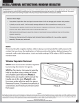
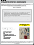
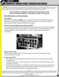
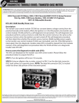
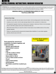
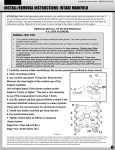
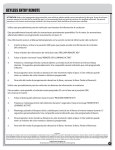
924-073
INSTALL INSTRUCTIONS: POWER SEAT TRACK
ATTENTION: Refer to the appropriate shop manual for your vehicle to obtain specific service procedures for this part. If you do not have
a service manual or lack the skill to install this part, it is recommended that you seek the services of a qualified technician. Pay special
attention to all cautions and warnings included in the shop manual. Read and follow all instructions carefully.
Tools required for proper removal of motor and regulator:
•
•
•
•
•
•
•
•
•
•
•
12 Point 15MM Deep Socket
12 Point 5/16” Shallow Socket (Or E-10)
12 Point 7/16” Shallow Socket (Or E-14)
12 Point 3/8” Shallow Socket (Or E-12)
12 Point 3/8” Shallow Socket ¼” Drive
3” ¼” Drive Extension
Appropriate Ratchets and at Least a 3”
Extension for Above Sockets
15MM Wrench
T-20 Screwdriver
Bench Mounted Vice
Small Ball Peen Hammer
•
•
•
•
•
•
•
•
Small Punch
Assortment of Flathead Screwdrivers
Piece Of Sandpaper
Small Tube of Loc-Tite
(Medium Removable Strength)
Small Amount of Grease (Any Common
Automotive Grease is Fine)
Large Piece of Cardboard (To Protect Seats
When Upside Down on Floor)
Roll of Teflon Tape
Paper Towel or Rags
STEP 1: Move the seat to the most rear-ward
position to gain access to the front two nuts. Using
the 15 MM deep 12 point socket, remove the nuts
from both rails.
STEP 2: Now move the seat to the most forward
and upward position (very important to ensure lead
screw alignment).
STEP 3: Remove plastic trim cover near inboard rail
by pulling straight upward on it. This will take some
force if it hasn’t been off before. Now remove the
two rear rail bolts using your ratchet and 7/16” 12
Point shallow socket. These will also come out hard
if they have not been out before.
Disclaimer:
Even though every attempt is made to ensure this information is complete and accurate, it is impossible to account for all possible circumstances or situations. Please consult with a qualified auto technician
before attempting to perform any work you are not qualified to do. Automobiles can be hazardous to work on; be sure to take all necessary safety precautions. Failure to do so may result in property damage
or personal injury. Certain motor vehicle standards and performance requirements may apply to your motor vehicle (such as Federal Motor Vehicle Safety Standards by the National Highway Traffic Safety
Administration). Be sure that your work is performed in accordance with such standards and that you do not disable any motor vehicle safety feature.
©2012 Dorman Products, Inc.
No reproductions in whole or in part without prior written approval.
1
924-073
INSTALL INSTRUCTIONS: POWER SEAT TRACK
ATTENTION: Refer to the appropriate shop manual for your vehicle to obtain specific service procedures for this part. If you do not have
a service manual or lack the skill to install this part, it is recommended that you seek the services of a qualified technician. Pay special
attention to all cautions and warnings included in the shop manual. Read and follow all instructions carefully.
STEP 4: Unplug electrical connector underneath the
front of the seat by depressing lock tab and pulling
on vehicle end of harness and position harness
out of the way so the seat does not catch on it
upon removal. Note the factory routing so it can be
routed in the same position as before.
STEP 5: Remove seat by pulling straight upward
so that the rail mounting points will clear the front
studs and carefully remove from vehicle (have an
assistant if necessary and be careful not to scratch
the paint!). Designate a clean work area (large piece
of cardboard works) and position the seat as shown
to allow comfortable access to working on the track.
STEP 6: Using the ratchet and the 5/16” 12 point
socket, remove the two bolts holding the aluminum
block assembly to the outboard rail (the rail nearest
the outside of the vehicle) and position aside.
STEP 7: Using a ratchet and the15mm deep-well
12 point socket, remove the the two nuts as shown
above from the rail to floor mounting bracket
and remove bracket from rail noting position of
bracket. There is one regular hole and one oblong
hole, make a mark on both the rail and bracket if
necessary to ensure proper installation later. Now
using the ball peen hammer and supporting the
rail from the other side with your hand, carefully
drive out the rear stud to allow rail to slide back far
enough to access to the screw and block assembly
retaining bolt through large hole found between
the two studs.
Disclaimer:
Even though every attempt is made to ensure this information is complete and accurate, it is impossible to account for all possible circumstances or situations. Please consult with a qualified auto technician
before attempting to perform any work you are not qualified to do. Automobiles can be hazardous to work on; be sure to take all necessary safety precautions. Failure to do so may result in property damage
or personal injury. Certain motor vehicle standards and performance requirements may apply to your motor vehicle (such as Federal Motor Vehicle Safety Standards by the National Highway Traffic Safety
Administration). Be sure that your work is performed in accordance with such standards and that you do not disable any motor vehicle safety feature.
©2012 Dorman Products, Inc.
No reproductions in whole or in part without prior written approval.
2
924-073
INSTALL INSTRUCTIONS: POWER SEAT TRACK
ATTENTION: Refer to the appropriate shop manual for your vehicle to obtain specific service procedures for this part. If you do not have
a service manual or lack the skill to install this part, it is recommended that you seek the services of a qualified technician. Pay special
attention to all cautions and warnings included in the shop manual. Read and follow all instructions carefully.
STEP 8: Now slide rail back until you can access the
bolt retaining the screw and block assembly to the
rail. There is a nut on the back side of the rail that
must be held for bolt removal. Using the 15mm
wrench, slide wrench through side access hole as
shown above and secure nut on backside of rail
and remove bolt using the 3/8” 12 point shallow
socket and ratchet. The nut is flanged and will stay
on wrench provided you do nut turn the wrench
upside down, so simply slide wrench out of access
hole after bolt is removed and set aside.
STEP 9: Holding rail towards back of seat, use the
T-20 screwdriver to remove the two bolts attaching
the drive mechanism to the rail and pull driveshaft
out of screw assembly by pulling straight back and
position out of the way of the screw assembly.
Please note: Be very gentle when tightening the two bolts attaching the drive
assembly to the rail, these do not need to be very tight to retain the drive assembly
and the aluminum drive can be stripped very easily if over tightened.
STEP 10: Now push end of screw assembly out of
plastic bushing toward rear of seat as shown above,
then slide the rail to gain access to screw assembly
mounting bracket on other end of rail. Using a
flathead screwdriver, pivot bracket 180 degrees. This
will take some patience as it is a tight clearance, but
is necessary for the screw and block assembly to
clear the rivet located on the rail for removal of the
assembly.
STEP 11: Sliding the rail to the most rearward
position (towards seat back), use both hands and
push from one end of the screw and block assembly
and pull from the bracket you rotated 180 degrees
(some wiggling is necessary) and remove rod and
block assembly from rear side of track.
Disclaimer:
Even though every attempt is made to ensure this information is complete and accurate, it is impossible to account for all possible circumstances or situations. Please consult with a qualified auto technician
before attempting to perform any work you are not qualified to do. Automobiles can be hazardous to work on; be sure to take all necessary safety precautions. Failure to do so may result in property damage
or personal injury. Certain motor vehicle standards and performance requirements may apply to your motor vehicle (such as Federal Motor Vehicle Safety Standards by the National Highway Traffic Safety
Administration). Be sure that your work is performed in accordance with such standards and that you do not disable any motor vehicle safety feature.
©2012 Dorman Products, Inc.
No reproductions in whole or in part without prior written approval.
3
924-073
INSTALL INSTRUCTIONS: POWER SEAT TRACK
ATTENTION: Refer to the appropriate shop manual for your vehicle to obtain specific service procedures for this part. If you do not have
a service manual or lack the skill to install this part, it is recommended that you seek the services of a qualified technician. Pay special
attention to all cautions and warnings included in the shop manual. Read and follow all instructions carefully.
STEP 12: Shown above is the removed screw
and block assembly. You can now see why it was
necessary to have the seat all the way forward so
the block assembly is tight against the end of the
screw assembly to allow perfect alignment upon reinstalling block assembly. Wiggling block assembly
back and forth you should now also be able to see
where that back and forth seat movement was
coming from. The rubber bushing degrades with
time and allows the free movement of the block
assembly. Utilizing this repair kit, the special nylon
will not fail as the original rubber has as shown
above. Thread aluminum block assembly all the way
off of lead screw and then remove remaining rubber
bushing as well as threaded steel block nut, and
clean all parts thoroughly.
STEP 13: Now take the machined special nylon
washers and insert them in block as shown above
with one flat side down and one flat side visible (the
only side visible when the washers are installed in
the block, also noting that the “peak“ on the steel
nut should be up and visible). They will be a snug
fit, use the screwdriver as a punch and very lightly
tap them in with the hammer if needed, you want
these to have a tight, zero clearance fit. If unable
to insert them with light force, sand the face down
slightly with the sandpaper constantly checking
your progress to maintain a zero clearance fit
between the steel block nut and aluminum housing
(you shouldn’t have to as they are machined within
.004“). When you get the washers seated in the
block, look through center of block assembly to
ensure the hole through the center of the washers
are aligned with the hole in the threaded steel block
and the top flat of the washers are flush or slightly
below the ridge of the aluminum block assembly.
If not, try pushing the washers in further or pulling
them slightly up to align the holes and assure a
flush fit with the aluminum block assembly.
Disclaimer:
Even though every attempt is made to ensure this information is complete and accurate, it is impossible to account for all possible circumstances or situations. Please consult with a qualified auto technician
before attempting to perform any work you are not qualified to do. Automobiles can be hazardous to work on; be sure to take all necessary safety precautions. Failure to do so may result in property damage
or personal injury. Certain motor vehicle standards and performance requirements may apply to your motor vehicle (such as Federal Motor Vehicle Safety Standards by the National Highway Traffic Safety
Administration). Be sure that your work is performed in accordance with such standards and that you do not disable any motor vehicle safety feature.
©2012 Dorman Products, Inc.
No reproductions in whole or in part without prior written approval.
4
924-073
INSTALL INSTRUCTIONS: POWER SEAT TRACK
ATTENTION: Refer to the appropriate shop manual for your vehicle to obtain specific service procedures for this part. If you do not have
a service manual or lack the skill to install this part, it is recommended that you seek the services of a qualified technician. Pay special
attention to all cautions and warnings included in the shop manual. Read and follow all instructions carefully.
STEP 14: Wipe the grease off of the screw assembly
and lightly apply new grease, working it up and
down the screw. Afterwards, thread aluminum
block assembly back onto screw assembly (one
screw is left hand thread, one is right hand thread)
and continue to thread up the screw until it is fully
seated against the end of the screw as shown.
STEP 15: Finally, insert the screw and block
assembly back into the seat track and place the
stud that you tapped out of the rail in step 7 in a
suitable vice. Using the flange nut that you took off
the stud, work the nut back and forth on the bolt
numerous times until you can easily thread the nut
at least halfway up the block by hand to ensure stud
will not spin when you tighten the nut back up. For
re-assembly, reverse procedure starting with step 10
and working your way back to the beginning, being
sure that you use Loc-Tite on the bolts. You may
need the punch (and hammer) to re-seat the stud
removed in step 7.
Disclaimer:
Even though every attempt is made to ensure this information is complete and accurate, it is impossible to account for all possible circumstances or situations. Please consult with a qualified auto technician
before attempting to perform any work you are not qualified to do. Automobiles can be hazardous to work on; be sure to take all necessary safety precautions. Failure to do so may result in property damage
or personal injury. Certain motor vehicle standards and performance requirements may apply to your motor vehicle (such as Federal Motor Vehicle Safety Standards by the National Highway Traffic Safety
Administration). Be sure that your work is performed in accordance with such standards and that you do not disable any motor vehicle safety feature.
©2012 Dorman Products, Inc.
No reproductions in whole or in part without prior written approval.
5