1
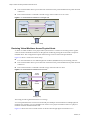
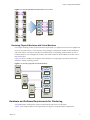
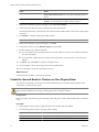
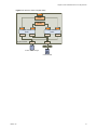
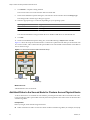
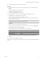
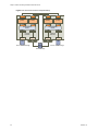
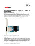
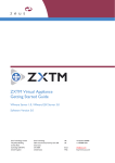
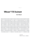
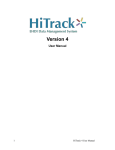
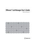
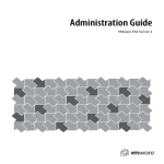
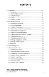
Setup for Failover Clustering and
Microsoft Cluster Service
ESX 4.0
ESXi 4.0
vCenter Server 4.0
This document supports the version of each product listed and
supports all subsequent versions until the document is replaced
by a new edition. To check for more recent editions of this
document, see http://www.vmware.com/support/pubs.
EN-000121-03
Setup for Failover Clustering and Microsoft Cluster Service
You can find the most up-to-date technical documentation on the VMware Web site at:
http://www.vmware.com/support/
The VMware Web site also provides the latest product updates.
If you have comments about this documentation, submit your feedback to:
[email protected]
Copyright © 2011 VMware, Inc. All rights reserved. This product is protected by U.S. and international copyright and intellectual
property laws. VMware products are covered by one or more patents listed at http://www.vmware.com/go/patents.
VMware is a registered trademark or trademark of VMware, Inc. in the United States and/or other jurisdictions. All other marks
and names mentioned herein may be trademarks of their respective companies.
VMware, Inc.
3401 Hillview Ave.
Palo Alto, CA 94304
www.vmware.com
2
VMware, Inc.
Contents
Updated Information 5
About This Book 7
1 Getting Started with MSCS 9
Clustering Configuration Overview 9
Hardware and Software Requirements for Clustering 11
Supported Shared Storage Configurations 12
vSphere MSCS Setup Limitations 12
MSCS and Booting from a SAN 13
Setting up a Continuous Clustered Replication Environment for Microsoft Exchange 13
2 Cluster Virtual Machines on One Physical Host 15
Create the First Node for Clusters on One Physical Host 15
Create the Second Node for Clusters on One Physical Host 16
Add Hard Disks to the First Node for Clusters on One Physical Host 17
Add Hard Disks to the Second Node for Clusters on One Physical Host 18
3 Cluster Virtual Machines Across Physical Hosts 21
Create the First Node for Clusters Across Physical Hosts 21
Create the Second Node for Clusters Across Physical Hosts 22
Add Hard Disks to the First Node for Clusters Across Physical Hosts 23
Add Hard Disks to the Second Node for Clusters Across Physical Hosts 24
4 Cluster Physical and Virtual Machines 27
Create the First Node for a Cluster of Physical and Virtual Machines 27
Create the Second Node for a Cluster of Physical and Virtual Machines 28
Add Hard Disks to the Second Node for a Cluster of Physical and Virtual Machines 29
Install Microsoft Cluster Service 30
Create Additional Physical-Virtual Pairs 30
5 Upgrade Clustered Virtual Machines 31
6 vSphere MSCS Setup Checklist 33
Index 35
VMware, Inc.
3
Setup for Failover Clustering and Microsoft Cluster Service
4
VMware, Inc.
Updated Information
This Setup for Failover Clustering and Microsoft Cluster Service guide is updated with each release of the product
or when necessary.
This table provides the update history of the Setup for Failover Clustering and Microsoft Cluster Service guide.
Table 1.
Revision
Description
000121-03
n
Minor change in “Setting up a Continuous Clustered Replication Environment for
Microsoft Exchange,” on page 13 section.
000121-02
n
Added one more point in “vSphere MSCS Setup Limitations,” on page 12 section
000121-01
n
The topic “vSphere MSCS Setup Limitations,” on page 12 now states that
clustering with iSCSI, FCoE, and NFS is not supported.
Minor revisions.
n
000121-00
VMware, Inc.
Initial release.
5
Setup for Failover Clustering and Microsoft Cluster Service
6
VMware, Inc.
About This Book
This book, Setup for Failover Clustering and Microsoft Cluster Service, describes the types of clusters you can
implement using virtual machines with Microsoft Cluster Service for Windows Server 2000 and Windows
Server 2003, and Failover Clustering for Windows Server 2008. You get step-by-step instructions for each type
of cluster and a checklist of clustering requirements and recommendations.
Unless stated otherwise, the term Microsoft Cluster Service (MSCS) applies to Microsoft Cluster Service with
Windows 2000 Server and Windows Server 2003 and Failover Clustering with Windows Server 2008.
®
Setup for Failover Clustering and Microsoft Cluster Service covers ESX, ESXi, and VMware vCenter Server.
Intended Audience
This book is for system administrators who are familiar with VMware technology and Microsoft Cluster
Service.
NOTE This is not a guide to using Microsoft Cluster Service or Failover Clustering. Use your Microsoft
documentation for information about installation and configuration of Microsoft Cluster Service or
Failover Clustering.
Document Feedback
VMware welcomes your suggestions for improving our documentation. If you have comments, send your
feedback to [email protected].
VMware vSphere Documentation
The vSphere documentation consists of the combined VMware vCenter Server and ESX/ESXi documentation
set.
Abbreviations Used in Figures
The figures in this book use the abbreviations listed in Table 2.
Table 2. Abbreviations
Abbreviation
Description
FC
Fibre Channel
SAN
Storage area network type datastore shared between managed hosts
VM#
Virtual machines on a managed host
VMware, Inc.
7
Setup for Failover Clustering and Microsoft Cluster Service
Table 2. Abbreviations (Continued)
Abbreviation
Description
VNIC
Virtual NIC
VSCSI
Virtual SCSI adapter
Technical Support and Education Resources
The following technical support resources are available to you. To access the current version of this book and
other books, go to http://www.vmware.com/support/pubs.
Online and Telephone
Support
To use online support to submit technical support requests, view your product
and contract information, and register your products, go to
http://www.vmware.com/support.
Customers with appropriate support contracts should use telephone support
for the fastest response on priority 1 issues. Go to
http://www.vmware.com/support/phone_support.html.
8
Support Offerings
To find out how VMware support offerings can help meet your business needs,
go to http://www.vmware.com/support/services.
VMware Professional
Services
VMware Education Services courses offer extensive hands-on labs, case study
examples, and course materials designed to be used as on-the-job reference
tools. Courses are available onsite, in the classroom, and live online. For onsite
pilot programs and implementation best practices, VMware Consulting
Services provides offerings to help you assess, plan, build, and manage your
virtual environment. To access information about education classes,
certification programs, and consulting services, go to
http://www.vmware.com/services.
VMware, Inc.
Getting Started with MSCS
1
®
VMware vSphere supports clustering using MSCS across virtual machines. Clustering virtual machines can
reduce the hardware costs of traditional high-availability clusters.
NOTE VMware High Availability (HA) supports a clustering solution in conjunction with vCenter Server
clusters. The Availability Guide describes VMware HA functionality.
This chapter includes the following topics:
n
“Clustering Configuration Overview,” on page 9
n
“Hardware and Software Requirements for Clustering,” on page 11
n
“Supported Shared Storage Configurations,” on page 12
n
“vSphere MSCS Setup Limitations,” on page 12
n
“MSCS and Booting from a SAN,” on page 13
n
“Setting up a Continuous Clustered Replication Environment for Microsoft Exchange,” on page 13
Clustering Configuration Overview
Several applications use clustering, including stateless applications such as Web servers, and applications with
built-in recovery features such as database servers. You can set up MSCS clusters in several configurations,
depending on your environment.
A typical clustering setup includes:
n
Disks that are shared between nodes. A shared disk is required as a quorum disk. In a cluster of virtual
machines across physical hosts, the shared disk must be on a Fibre Channel (FC) SAN.
n
A private heartbeat network between nodes.
You can set up the shared disks and private heartbeat using one of several clustering configurations.
Clustering Virtual Machines on a Single Host
A cluster of virtual machines on a single host (also known as a cluster in a box) consists of two clustered virtual
machines on the same ESX/ESXi host connected to the same storage, either local or remote. This configuration
protects against failures at the operating system and application level, but it does not protect against hardware
failures.
Figure 1-1 shows a cluster in a box setup.
n
VMware, Inc.
Two virtual machines on the same physical machine (ESX/ESXi host) run clustering software.
9
Setup for Failover Clustering and Microsoft Cluster Service
n
The virtual machines share a private network connection for the private heartbeat and a public network
connection.
n
Each virtual machine is connected to shared storage, which can be local or on a SAN.
Figure 1-1. Virtual Machines Clustered on a Single Host
private
network
virtual machine
Node1
cluster
software
virtual machine
Node2
cluster
software
public
network
physical machine
storage (local or SAN)
Clustering Virtual Machines Across Physical Hosts
A cluster of virtual machines across physical hosts (also known as a cluster across boxes) protects against
software failures and hardware failures on the physical machine by placing the cluster nodes on separate
ESX/ESXi hosts. This configuration requires shared storage on an FC SAN for the quorum disk.
Figure 1-2 shows a cluster-across-boxes setup.
n
Two virtual machines on two different physical machines (ESX/ESXi hosts) run clustering software.
n
The virtual machines share a private network connection for the private heartbeat and a public network
connection.
n
Each virtual machine is connected to shared storage, which must be on a SAN.
Figure 1-2. Virtual Machines Clustered Across Hosts
private
network
virtual machine
Node1
cluster
software
virtual machine
Node2
cluster
software
public
network
physical machine
physical machine
storage (SAN)
This setup provides significant hardware cost savings.
You can expand the cluster-across-boxes model and place multiple virtual machines on multiple physical
machines. For example, you can consolidate four clusters of two physical machines each to two physical
machines with four virtual machines each.
Figure 1-3 shows how four two-node clusters can be moved from eight physical machines to two.
10
VMware, Inc.
Chapter 1 Getting Started with MSCS
Figure 1-3. Clustering Multiple Virtual Machines Across Hosts
1
2
3
4
5
7
6
8
VM1
VM2
VM3
VM4
VM5
VM6
VM7
VM8
physical
machine
physical
machine
Clustering Physical Machines with Virtual Machines
For a simple clustering solution with low hardware requirements, you might choose to have one standby host.
Set up your system to have a virtual machine corresponding to each physical machine on the standby host,
and create clusters, one each for each physical machine and its corresponding virtual machine. In case of
hardware failure in one of the physical machines, the virtual machine on the standby host can take over for
that physical host.
Figure 1-4 shows a standby host using three virtual machines on a single physical machine. Each virtual
machine is running clustering software.
Figure 1-4. Clustering Physical and Virtual Machines
virtual
machine
cluster
software
cluster
software
virtual
machine
cluster
software
cluster
software
virtual
machine
cluster
software
cluster
software
physical
machine
Hardware and Software Requirements for Clustering
All vSphere MSCS configurations require certain hardware and software components.
Table 1-1 lists hardware and software requirements that apply to all vSphere MSCS configurations.
VMware, Inc.
11
Setup for Failover Clustering and Microsoft Cluster Service
Table 1-1. Clustering Requirements
Component
Requirement
Virtual SCSI adapter
LSI Logic Parallel for Windows 2000 Server
LSI Logic Parallel for Windows Server 2003
LSI Logic SAS for Windows Server 2008
Operating system
Windows Server 2003 SP2, Windows 2000 Server SP4, or Windows Server 2008
Virtual NIC
Use the default type for all guest operating systems.
I/O timeout
Set to 60 seconds or more. Modify
HKEY_LOCAL_MACHINE\System\CurrentControlSet\Services\Disk\TimeOutValue.
The system might reset this I/O timeout value if you recreate a cluster. You must reset the value
in that case.
Disk format
Select Support clustering features such as Fault Tolerance to create disks in
eagerzeroedthick format.
Disk and networking
setup
Add networking before disks. Refer to the VMware knowledge base article at
http://kb.vmware.com/kb/1513 if you encounter any errors.
Number of nodes
Use two-node clustering.
NTP server
Synchronize domain controllers and cluster nodes with a common NTP server, and disable hostbased time synchronization when using clustering in the guest.
Supported Shared Storage Configurations
Different MSCS cluster setups support different types of shared storage configurations. Some setups support
more than one type. Select the recommended type of shared storage for best results.
Table 1-2 lists supported setups for each clustering solution.
Table 1-2. Shared Storage Requirements
Storage Type
Clusters on One Physical
Machine
(Cluster in a Box)
Clusters Across
Physical Machines
(Cluster Across
Boxes)
Clusters of Physical
and Virtual Machines
(Standby Host
Clustering)
Virtual disks
Yes
(recommended)
No
No
Pass-through RDM
(physical compatibility mode)
No
Yes
(recommended)
Yes
Non-pass-through RDM
(virtual compatibility mode)
Yes
Yes
No
NOTE Clusters across physical machines with non-pass-through RDM is supported only for clustering with
Windows 2000 Server or Windows Server 2003. It is not supported for clustering with Windows Server 2008.
vSphere MSCS Setup Limitations
Before you set up MSCS, review the list of functionality that is not supported for this release, and any
requirements and recommendations that apply to your configuration.
The following environments and functionality are not supported for MSCS setups with this release of vSphere:
12
n
Clustering on iSCSI, FCoE, and NFS disks.
n
Mixed environments, such as configurations where one cluster node is running a different version of
ESX/ESXi than another cluster node.
VMware, Inc.
Chapter 1 Getting Started with MSCS
n
Clustered virtual machines as part of VMware clusters (DRS or HA).
n
Use of MSCS in conjunction with VMware Fault Tolerance.
n
Migration with VMotion of clustered virtual machines.
n
N-Port ID Virtualization (NPIV)
n
With native multipathing (NMP), clustering is not supported when the path policy is set to round robin.
n
You must use hardware version 7 with ESX/ESXi 4.0.
n
With native multipathing (NMP), clustering is not supported when the path policy is set to round robin.
Third-party multipathing plug-ins might support round robin or other load balancing behavior with
Microsoft clusters. Support of third-party multipathing plug-ins is provided by the plug-in vendor.
MSCS and Booting from a SAN
You can put the boot disk of a virtual machine on a SAN-based VMFS volume.
MSCS is supported in a setup where virtual machines boot from an FC SAN.
Booting from a SAN is complex. Problems that you encounter in physical environments extend to virtual
environments. For general information about booting from a SAN, see the Fibre Channel SAN Configuration
Guide.
Follow these guidelines when you place the boot disk of a virtual machine on a SAN-based VMFS volume:
n
Consider the best practices for boot-from-SAN that Microsoft publishes in the following knowledge base
article: http://support.microsoft.com/kb/305547/en-us.
n
Use StorPort LSI Logic drivers instead of SCSIport drivers when running Microsoft Cluster Service for
Windows Server 2003 or 2008 guest operating systems.
n
Test clustered configurations in different failover scenarios before you put them into production
environments.
Setting up a Continuous Clustered Replication Environment for
Microsoft Exchange
You can set up a Continuous Cluster Replication or Database Availability Groups with Exchange 2010 in your
vSphere environment.
When working in a vSphere environment:
n
Use virtual machines instead of physical machines as the cluster components.
n
Use physical compatibility mode RDMs.
If the boot disks of the CCR virtual machines are on a SAN, refer to “MSCS and Booting from a SAN,” on
page 13.
For more information, refer to Microsoft’s documentation for CCR clusters on the Microsoft Web site.
VMware, Inc.
13
Setup for Failover Clustering and Microsoft Cluster Service
14
VMware, Inc.
Cluster Virtual Machines on One
Physical Host
2
You can create a two-node MSCS cluster on a single ESX/ESXi host.
Prerequisites
A cluster of virtual machines on one physical machine requires an ESX/ESXi host with the following:
n
For ESX hosts, use one physical network adapter for the service console. Use a separate physical network
adapter for clustered virtual machines to connect with external hosts.
n
For ESXi, use one physical network adapter for the VMkernel. Use a separate physical network adapter
for clustered virtual machines to connect with external hosts.
This chapter includes the following topics:
n
“Create the First Node for Clusters on One Physical Host,” on page 15
n
“Create the Second Node for Clusters on One Physical Host,” on page 16
n
“Add Hard Disks to the First Node for Clusters on One Physical Host,” on page 17
n
“Add Hard Disks to the Second Node for Clusters on One Physical Host,” on page 18
Create the First Node for Clusters on One Physical Host
To create the first node, you create and configure a virtual machine with two virtual network adapters and
install a guest operating system on the virtual machine.
You configure the virtual network adapters to handle virtual machine traffic for the cluster: a private network
connection for the private heartbeat and a public network connection.
Procedure
1
Open the vSphere Client and connect to the ESX/ESXi host or a vCenter Server system.
Use the user name and password of the user who will own the virtual machine.
2
In the vSphere Client inventory, right-click the host and select New Virtual Machine.
3
Proceed through the wizard to create the virtual machine.
VMware, Inc.
Option
Action
Configuration
Select Typical.
Name and Location
Enter a name and select a location.
Datastore
Select a datastore as the location for the virtual machine configuration file
and the virtual machine disk (.vmdk) file.
Guest Operating System
Select the Windows Server operating system that you intend to install.
15
Setup for Failover Clustering and Microsoft Cluster Service
Option
Action
Create Disk
Enter the appropriate value in Virtual disk size. Select Support clustering
features such as Fault Tolerance to create a disk in eagerzeroedthick
format.
Ready to Complete
Select Edit the virtual machine settings before completion and click
Continue. The Virtual Machine Properties dialog box appears.
4
In the Virtual Machine Properties dialog box, select New NIC (adding).
5
Under Network Connection, select a label from the Network Label list.
The network label refers to the network to be used for virtual machine traffic for the cluster, either public
or private.
6
Click Finish to complete creating the virtual machine.
NOTE Do not add shared cluster disks at this time.
7
In the Virtual Machine Properties dialog box, click Add.
8
From the list of devices, select Ethernet Adapter and click Next.
9
Select the adapter type and network label.
n
If you selected a private network for the first network adapter, you must select a public network for
this network adapter.
n
If you selected a public network for the first network adapter, you must select a private network
adapter.
10
Click Next, and click Finish to complete creating the device.
11
Install a Windows Server operating system on the virtual machine.
The new node appears in the virtual machine inventory.
What to do next
Clone the virtual machine to create the second node.
Create the Second Node for Clusters on One Physical Host
To create the second node, you clone the first virtual machine that you created using the vSphere Client
connected to a vCenter Server system.
CAUTION If you clone a virtual machine with an RDM setup, the cloning process converts the RDMs to virtual
disks. Unmap all RDMs before cloning, and remap them after cloning is complete.
Prerequisites
Before you begin, shut down the guest operating system and power off the virtual machine that you intend to
clone.
Procedure
16
1
In the vSphere Client inventory, right-click the virtual machine and select Clone.
2
Proceed through the wizard to clone the virtual machine.
Page
Action
Name and Location
Enter a name (for example, Node2_Template) and select a location.
Host/Cluster
Select the host or cluster where you will run the virtual machine.
VMware, Inc.
Chapter 2 Cluster Virtual Machines on One Physical Host
Page
Action
Datastore
Select a datastore as the location for the virtual machine configuration file
and the .vmdk file.
Disk Format
Select Same format as source.
Customization
Select Do not customize.
Ready to Complete
Click Finish to create the virtual machine.
You have created a virtual machine with two network adapters. The operating system you chose for the first
node is installed on the second node.
What to do next
Add a shared quorum disk.
Add Hard Disks to the First Node for Clusters on One Physical Host
In an MSCS cluster, storage disks are shared between nodes. You set up a quorum disk and an optional shared
storage disk.
Procedure
1
In the vSphere Client inventory, select the newly created virtual machine and select Edit Settings.
The Virtual Machine Properties dialog box appears.
2
Click Add, select Hard Disk, and click Next.
3
Select Create a new virtual disk and click Next.
4
Select the disk size.
5
Under Disk Provisioning, select Support clustering features such as Fault Tolerance.
You can also use a mapped SAN LUN set to virtual compatibility mode.
6
Click Next.
7
From the Virtual Device Node drop-down menu, select a new SCSI controller (for example, SCSI (1:0)).
NOTE You must select a new virtual device node. You cannot use SCSI 0.
8
Click Next, and click Finish.
The wizard creates a new hard disk and a new SCSI controller.
9
In the Virtual Machine Properties dialog box, select the new SCSI controller and click Change Type.
The Change SCSI Controller Type dialog box appears.
10
Select the appropriate type of controller, depending on your operating system.
Operating System
Type of Controller
Windows 2000 Server
LSI Logic Parallel
Windows Server 2003
LSI Logic Parallel
Windows Server 2008
LSI Logic SAS
You must download the LSI Logic Parallel driver for Windows 2000 Server on the LSI Web site.
11
Click OK.
12
On the Virtual Machine Properties dialog box, set SCSI Bus Sharing to Virtual and click OK.
VMware, Inc.
17
Setup for Failover Clustering and Microsoft Cluster Service
Figure 2-1 shows the setup: a virtual machine connected to the shared storage on the Fibre Channel (FC) SAN
and to local or remote storage for the virtual disk. The virtual machine has two available network connections,
one for the private heartbeat and one for public communications.
Figure 2-1. Cluster in a Box Setup for One Node
NIC1
virtual switch1
virtual switch2
VNIC1
VNIC2
virtual machine
Node1
VSCSI1
VSCSI2
SCSI1
SCSI2
physical
machine
FC
local or remote storage
remote storage
What to do next
Add hard disks to the second node.
Add Hard Disks to the Second Node for Clusters on One Physical Host
To allow shared access to clustered services and data, point the quorum disk of the second node to the same
location as the first node’s quorum disk. Point any shared storage disks to the same location as the first node’s
shared storage disks.
Prerequisites
Before you begin, obtain the following information:
n
Which virtual device node is for the first virtual machine's shared storage disks (for example, SCSI (1:0)).
n
The location of the quorum disk specified for the first node.
Procedure
1
In the vSphere Client inventory, select the second virtual machine that you created and select Edit
Settings.
The Virtual Machine Properties dialog box appears.
2
Click Add, select Hard Disk, and click Next.
3
Select Use an existing virtual disk and click Next.
4
Select the same virtual device node you chose for the first virtual machine’s shared storage disks (for
example, SCSI (1:0)), and click Next.
NOTE The location of the virtual device node for this virtual machine’s shared storage must match the
corresponding virtual device node for the first virtual machine.
5
In Disk File Path, browse to the location of the quorum disk specified for the first node.
Figure 2-2 shows the complete setup.
18
VMware, Inc.
Chapter 2 Cluster Virtual Machines on One Physical Host
Figure 2-2. Cluster in a Box Complete Setup
NIC1
virtual switch1
(public)
virtual switch2
(private)
VNIC1
VNIC2
virtual machine
Node1
VSCSI1
physical machine
VNIC2
VNIC1
virtual machine
Node2
VSCSI2
VSCSI2
SCSI1
SCSI2
VSCSI1
FC
local or remote storage
remote storage
VMware, Inc.
19
Setup for Failover Clustering and Microsoft Cluster Service
20
VMware, Inc.
Cluster Virtual Machines Across
Physical Hosts
3
You can create a MSCS cluster that consists of two virtual machines on two ESX/ESXi hosts.
Prerequisites
A cluster across physical hosts requires specific hardware and software.
n
ESX/ESXi hosts that have the following:
n
Two physical network adapters dedicated to the MSCS cluster and to the public and private networks.
n
One physical network adapter dedicated to the service console (ESX hosts) or the VMkernel (ESXi
hosts).
n
Fibre Channel (FC) SAN. Shared storage must be on an FC SAN.
n
RDM in physical compatibility (pass-through) or virtual compatibility (non-pass-through) mode. VMware
recommends physical compatibility mode. The cluster cannot use virtual disks for shared storage.
Failover clustering with Windows Server 2008 is not supported with virtual compatibility mode (nonpass-through) RDMs.
This chapter includes the following topics:
n
“Create the First Node for Clusters Across Physical Hosts,” on page 21
n
“Create the Second Node for Clusters Across Physical Hosts,” on page 22
n
“Add Hard Disks to the First Node for Clusters Across Physical Hosts,” on page 23
n
“Add Hard Disks to the Second Node for Clusters Across Physical Hosts,” on page 24
Create the First Node for Clusters Across Physical Hosts
To create the first node, you create and configure a virtual machine with two virtual network adapters and
install a guest operating system on the virtual machine.
You configure the virtual network adapters to handle virtual machine traffic for the cluster: a private network
connection for the private heartbeat and a public network connection.
Procedure
1
Open the vSphere Client and connect to the ESX/ESXi host or a vCenter Server system.
Use the user name and password of the user who will own the virtual machine.
2
VMware, Inc.
In the vSphere Client inventory, right-click the host and select New Virtual Machine.
21
Setup for Failover Clustering and Microsoft Cluster Service
3
Proceed through the wizard to create the virtual machine.
Option
Action
Configuration
Select Typical.
Name and Location
Enter a name and select a location.
Datastore
Select a datastore as the location for the virtual machine configuration file
and the virtual machine disk (.vmdk) file.
Guest Operating System
Select the Windows Server operating system that you intend to install.
Create Disk
Enter the appropriate value in Virtual disk size. Select Support clustering
features such as Fault Tolerance to create a disk in eagerzeroedthick
format.
Ready to Complete
Select Edit the virtual machine settings before completion and click
Continue. The Virtual Machine Properties dialog box appears.
4
In the Virtual Machine Properties dialog box, select New NIC (adding).
5
Under Network Connection, select a label from the Network Label list.
The network label refers to the network to be used for virtual machine traffic for the cluster, either public
or private.
6
Click Finish to complete creating the virtual machine.
NOTE Do not add shared cluster disks at this time.
7
In the Virtual Machine Properties dialog box, click Add.
8
From the list of devices, select Ethernet Adapter and click Next.
9
Select the adapter type and network label.
n
If you selected a private network for the first network adapter, you must select a public network for
this network adapter.
n
If you selected a public network for the first network adapter, you must select a private network
adapter.
10
Click Next, and click Finish to complete creating the device.
11
Install a Windows Server operating system on the virtual machine.
The new node appears in the virtual machine inventory.
What to do next
Clone the virtual machine to create the second node.
Create the Second Node for Clusters Across Physical Hosts
To create the second node in a cluster of virtual machines across physical hosts, you clone the first virtual
machine you created onto a second ESX/ESXi host using the vSphere Client connected to a vCenter Server
system.
CAUTION If you clone a virtual machine with an RDM setup, the cloning process converts the RDMs to virtual
disks. Unmap all RDMs before cloning, and remap them after cloning is complete.
Prerequisites
Before you begin, shut down the guest operating system and power off the virtual machine you intend to clone.
22
VMware, Inc.
Chapter 3 Cluster Virtual Machines Across Physical Hosts
Procedure
1
In the vSphere Client inventory, right-click the virtual machine and select Clone.
2
Proceed through the wizard to clone the virtual machine.
Page
Action
Name and Location
Enter a name and select a location.
Host or Cluster
Select the second host for the cluster setup.
Resource Partition
Select the resource pool for the virtual machine, or select the host if no
resource pools exist.
Datastore
Select a datastore as the location for the virtual machine configuration file
and the .vmdk file.
Customization
Select Do not customize.
Ready to Complete
Click OK to create the virtual machine template.
You have created a virtual machine with two network adapters. The operating system you chose for the first
node is installed on the second node.
What to do next
Add a shared quorum disk.
Add Hard Disks to the First Node for Clusters Across Physical Hosts
In an MSCS cluster, storage disks are shared between nodes. You set up a quorum disk and an optional shared
storage disk.
Prerequisites
Before you add hard disks to the first node, complete the following tasks:
n
For each virtual machine, configure the guest operating system’s private and public IP addresses.
n
Ask your SAN administrator for the location of unformatted SAN LUNs. The hard disks you create in this
task must point to SAN LUNs.
NOTE Use RDMs in physical compatibility mode. The procedure below uses physical compatibility mode.
Procedure
1
In the vSphere Client inventory, select the newly created virtual machine and select Edit Settings.
The Virtual Machine Properties dialog box appears.
2
Click Add, select Hard Disk, and click Next.
3
Select Raw Device Mappings and click Next.
4
Select an unformatted LUN and click Next.
5
Select a datastore and click Next.
This datastore must be on a SAN because you need a single shared RDM file for each shared LUN on the
SAN.
6
Select Physical as the compatibility mode and click Next.
A SCSI controller is created when the virtual hard disk is created.
7
Select a new virtual device node (for example, select SCSI (1:0)), and click Next.
NOTE This must be a new SCSI controller. You cannot use SCSI 0.
VMware, Inc.
23
Setup for Failover Clustering and Microsoft Cluster Service
8
Click Finish to complete creating the disk.
The wizard creates a new SCSI controller and a new hard disk.
9
In the Virtual Machine Properties dialog box, select the new SCSI controller and click Change Type.
The Change SCSI Controller Type dialog box appears.
10
Select the appropriate type of controller, depending on your operating system.
Operating System
Type of Controller
Windows 2000 Server
LSI Logic Parallel
Windows Server 2003
LSI Logic Parallel
Windows Server 2008
LSI Logic SAS
You must download the LSI Logic Parallel driver for Windows 2000 Server on the LSI Web site.
11
Click OK.
12
On the Virtual Machine Properties dialog box, set SCSI Bus Sharing to Physical and click OK.
Figure 3-1 shows the setup: the virtual machine is connected to a public network and a private network with
two virtual switches, and is connected to the quorum disk on FC SAN and the virtual machine virtual disk on
local or remote storage.
Figure 3-1. Cluster Across Boxes with First Node Set Up
NIC1
NIC2
virtual switch1
(public)
virtual switch2
(private)
VNIC1
VNIC2
virtual machine
Node1
VSCSI1
VSCSI2
physical
machine
SCSI1
SCSI2
FC
local or remote storage
remote storage
What to do next
Add hard disks to the second node.
Add Hard Disks to the Second Node for Clusters Across Physical Hosts
To allow shared access to clustered services and data, point the quorum disk of the second node to the same
location as the first node’s quorum disk. Point any shared storage disks to the same location as the first node’s
shared storage disks.
Prerequisites
Before you begin, obtain the following information:
n
24
Which virtual device node is for the first virtual machine's shared storage disks (for example, SCSI (1:0)).
VMware, Inc.
Chapter 3 Cluster Virtual Machines Across Physical Hosts
n
The location of the quorum disk specified for the first node.
Procedure
1
In the vSphere Client inventory, select the second virtual machine that you created and select Edit
Settings.
The Virtual Machine Properties dialog box appears.
2
Click Add, select Hard Disk, and click Next.
3
Select Use an existing virtual disk and click Next.
4
In Disk File Path, browse to the location of the quorum disk specified for the first node.
5
Select Physical as the compatibility mode and click Next.
A SCSI controller is created when the virtual hard disk is created.
6
Select the same virtual device node you chose for the first virtual machine’s shared storage disks (for
example, SCSI (1:0)), and click Next.
NOTE The location of the virtual device node for this virtual machine’s shared storage must match the
corresponding virtual device node for the first virtual machine.
7
Click Finish.
The wizard creates a new hard disk and a new SCSI controller.
8
In the Virtual Machine Properties dialog box, select the new SCSI controller and click Change Type.
The Change SCSI Controller Type dialog box appears.
9
Select the appropriate type of controller, depending on your operating system.
Operating System
Type of Controller
Windows 2000 Server
LSI Logic Parallel
Windows Server 2003
LSI Logic Parallel
Windows Server 2008
LSI Logic SAS
You must download the LSI Logic Parallel driver for Windows 2000 Server on the LSI Web site.
10
Click OK.
11
Set SCSI Bus Sharing to Physical and click OK.
Figure 3-2 shows the completed setup, including the shared storage on the quorum disk and the shared private
network.
VMware, Inc.
25
Setup for Failover Clustering and Microsoft Cluster Service
Figure 3-2. Cluster Across Boxes Complete Setup
NIC1
NIC2
NIC2
NIC1
virtual switch1
(public)
virtual switch2
(private)
virtual switch2
(private)
virtual switch1
(public)
VNIC1
VNIC2
VNIC2
VNIC1
virtual machine
Node1
VSCSI1
virtual machine
Node2
VSCSI2
VSCSI2
physical
machine
SCSI1
VSCSI1
physical
machine
SCSI2
SCSI2
FC
FC
local or remote storage
SCSI1
local or remote storage
remote storage
26
VMware, Inc.
Cluster Physical and Virtual Machines
4
You can create an MSCS cluster in which each physical machine has a corresponding virtual machine. This
type of configuration is known as a standby host cluster.
Prerequisites
A standby host cluster has specific hardware and software requirements.
n
Use ESX/ESXi hosts that have the following:
n
Two physical network adapters dedicated to the MSCS cluster and to the public and private networks.
n
One physical network adapter dedicated to the service console (ESX hosts) or the VMkernel (ESXi
hosts).
n
Use RDMs in physical compatibility mode (pass-through RDM). You cannot use virtual disks or RDMs
in virtual compatibility mode (non-pass-through RDM) for shared storage.
n
Use the STORport Miniport driver for the Fibre Channel (FC) HBA (QLogic or Emulex) in the physical
Windows machine.
n
Do not run multipathing software in the physical or virtual machines.
n
Use only a single physical path from the host to the storage arrays in standby host configurations.
This chapter includes the following topics:
n
“Create the First Node for a Cluster of Physical and Virtual Machines,” on page 27
n
“Create the Second Node for a Cluster of Physical and Virtual Machines,” on page 28
n
“Add Hard Disks to the Second Node for a Cluster of Physical and Virtual Machines,” on page 29
n
“Install Microsoft Cluster Service,” on page 30
n
“Create Additional Physical-Virtual Pairs,” on page 30
Create the First Node for a Cluster of Physical and Virtual Machines
The first node in a standby host setup is a physical machine.
For information about setting up a physical machine that participates in an MSCS cluster, see the Microsoft
Cluster Service documentation.
VMware, Inc.
27
Setup for Failover Clustering and Microsoft Cluster Service
Procedure
u
Set up the physical machine using the settings listed in the table.
Component
Requirement
Windows Cluster Administrator
application
Advanced minimum configuration if Windows 2003 is used.
Network adapters
At least two.
Storage
Access to the same storage on a SAN as the ESX/ESXi host on which the
corresponding virtual machine will run.
Operating system
Installed on each physical machine.
What to do next
Create the second node by setting up a virtual machine for clustering across physical machines.
Create the Second Node for a Cluster of Physical and Virtual Machines
To create the second node, you set up a virtual machine for clustering across physical machines.
You configure the virtual network adapters to handle virtual machine traffic for the cluster: a private network
connection for the private heartbeat and a public network connection.
Prerequisites
Before you begin, make sure that the shared storage that is visible from the physical machine that you
configured in “Create the First Node for a Cluster of Physical and Virtual Machines,” on page 27 is also visible
from the virtual machine.
Procedure
1
Open the vSphere Client and connect to the ESX/ESXi host.
Use the user name and password of the user who will own the virtual machine.
2
In the vSphere Client inventory, right-click the host and select New Virtual Machine.
3
Proceed through the wizard to create the virtual machine.
Option
Action
Configuration
Select Typical.
Name and Location
Enter a name and select a location.
Datastore
Select a datastore as the location for the virtual machine configuration file
and the virtual machine disk (.vmdk) file.
Guest Operating System
Select the Windows Server operating system that you intend to install.
Create Disk
Enter the appropriate value in Virtual disk size. Select Support clustering
features such as Fault Tolerance to create a disk in eagerzeroedthick
format.
Ready to Complete
Select Edit the virtual machine settings before completion and click
Continue. The Virtual Machine Properties dialog box appears.
4
In the Virtual Machine Properties dialog box, select New NIC (adding).
5
Under Network Connection, select a label from the Network Label list.
The network label refers to the network to be used for virtual machine traffic for the cluster, either public
or private.
6
28
Click Finish to complete creating the virtual machine.
VMware, Inc.
Chapter 4 Cluster Physical and Virtual Machines
7
In the Virtual Machine Properties dialog box, click Add.
8
From the list of devices, select Ethernet Adapter and click Next.
9
Select the adapter type and network label.
n
If you selected a private network for the first network adapter, you must select a public network for
this network adapter.
n
If you selected a public network for the first network adapter, you must select a private network
adapter.
10
Click Next, and click Finish to complete creating the device.
11
Install a Windows Server operating system on the virtual machine.
The new node appears in the virtual machine inventory.
What to do next
Add hard disks to the second node.
Add Hard Disks to the Second Node for a Cluster of Physical and Virtual
Machines
When you add hard disks to the second node, you set up the disks to point to the quorum disk and shared
storage disks, if any, for the first node. The setup allows shared access to clustered services and data.
Procedure
1
In the vSphere Client inventory, select the newly created virtual machine and select Edit Settings.
The Virtual Machine Properties dialog box appears.
2
Click Add, select Hard Disk, and click Next.
3
Select Raw Device Mappings and click Next.
4
Select the LUN that is used by the physical machine.
5
Select the datastore, which is also the location of the boot disk, and click Next.
6
Select Physical as the compatibility mode and click Next.
A SCSI controller is created when the virtual hard disk is created.
7
From the Virtual Device Node drop-down menu, select a new SCSI controller (for example, SCSI (1:0)).
NOTE You must select a new virtual device node. You cannot use SCSI 0.
8
Click Next, and click Finish.
The wizard creates a new hard disk and a new SCSI controller.
9
In the Virtual Machine Properties dialog box, select the new SCSI controller and click Change Type.
The Change SCSI Controller Type dialog box appears.
VMware, Inc.
29
Setup for Failover Clustering and Microsoft Cluster Service
10
Select the appropriate type of controller, depending on your operating system.
Operating System
Type of Controller
Windows 2000 Server
LSI Logic Parallel
Windows Server 2003
LSI Logic Parallel
Windows Server 2008
LSI Logic SAS
You must download the LSI Logic Parallel driver for Windows 2000 Server on the LSI Web site.
11
Click OK.
12
On the Virtual Machine Properties dialog box, set SCSI Bus Sharing to Physical and click OK.
What to do next
Install Microsoft Cluster Service.
Install Microsoft Cluster Service
For Windows Server 2003 operating systems only, after you set up the first and second nodes, you must
configure Microsoft Cluster Service.
See Microsoft’s documentation for creating and configuring server clusters on the Microsoft Web site.
In some complex storage solutions, such as an FC switched fabric, a particular storage unit might have a
different identity (target ID or raw disk ID) on each computer in the cluster. Although this is a valid storage
configuration, it causes a problem when you want to add a node to the cluster.
The following procedure allows you to avoid target identity problems when using clustering with Windows
2003.
Procedure
1
Within the Microsoft Cluster Administrator utility, on the Select Computer page, click Advanced to disable
the storage validation heuristics.
2
Select the Advanced (minimum) configuration option, and click OK.
Microsoft Cluster Service should operate normally in the virtual machine after it is installed.
What to do next
Create additional physical-virtual pairs, if necessary.
Create Additional Physical-Virtual Pairs
If you have additional physical machines, you can create additional clusters for each.
Procedure
30
1
On the ESX/ESXi host, set up an additional virtual machine for the physical machine.
2
Cluster the physical machine with the new virtual machine.
VMware, Inc.
Upgrade Clustered Virtual Machines
5
You can upgrade clustered virtual machines following the procedures in the Upgrade Guide. Perform upgrades
in the order listed for each upgrade scenario.
NOTE During the upgrade process, you do not need to change legacy configuration parameters that are not
listed in this guide.
Upgrade ESX 3.x to ESX 4.0
Upgrade ESX 3.x hosts to ESX 4.0 using the procedure Upgrading ESX 4.0 in the Upgrade Guide, ESX 4.0, ESXi
4.0, and vCenter Server 4.0.
Upgrade ESX 2.5.2 to ESX 4.0
You must follow these steps for the upgrade to complete successfully.
1
Upgrade ESX 2.5.2 hosts to ESX Server 3 using the procedure, Upgrading VMware ESX Server in the
Installation and Upgrade Guide, VMware Virtual Infrastructure.
2
Update clusters on ESX Server 3 hosts using the procedure, Updating Clusters in Setup for Microsoft Cluster
Service, ESX Server 3.0 and VirtualCenter 2.0.
3
Upgrade ESX 3.x hosts to ESX 4.0 using the procedure Upgrading ESX 4.0 in the Upgrade Guide, ESX 4.0,
ESXi 4.0, and vCenter Server 4.0.
VMware, Inc.
31
Setup for Failover Clustering and Microsoft Cluster Service
32
VMware, Inc.
6
vSphere MSCS Setup Checklist
When you set up MSCS on ESX/ESXi, refer to the checklists to configure your environment according to the
requirements. You can also use the checklists to verify that your setup meets the requirements if you need
technical support.
Requirements for Clustered Disks
Each type of clustered disk has its own requirements, depending on whether it is in a single-host cluster or
multihost cluster. Table 6-1 lists the requirements.
Table 6-1. Requirements for Clustered Disks
Component
Single-Host Clustering
Multihost Clustering
Clustered virtual disk (.vmdk)
SCSI bus sharing mode must be set
to virtual.
Not supported.
Clustered disks, virtual
compatibility mode (non-passthrough RDM)
Device type must be set to virtual
compatibility mode.
SCSI bus sharing mode must be set
to virtual mode.
A single, shared RDM mapping file
for each clustered disk is required.
Device type must be set to virtual compatibility
mode for cluster across boxes, but not for
standby host clustering or cluster across boxes
on Windows 2008.
SCSI bus sharing mode must be set to physical.
Requires a single, shared RDM mapping file for
each clustered disk.
Clustered disks, physical
compatibility mode (passthrough RDM)
Not supported.
Device type must be set to Physical
compatibility mode during hard disk creation.
SCSI bus sharing mode must be set to physical
(the default).
A single, shared RDM mapping file for each
clustered disk is required.
All types
All clustered nodes must use the same target ID (on the virtual SCSI adapter) for the
same clustered disk.
A separate virtual adapter must be used for clustered disks.
Other Requirements and Recommendations
Table 6-2 lists the components in your environment that have requirements for options or settings.
VMware, Inc.
33
Setup for Failover Clustering and Microsoft Cluster Service
Table 6-2. Other Clustering Requirements and Recommendations
Component
Requirement
Disk
If you place the boot disk on a virtual disk, select Support Clustering Features such as Fault
Tolerance during disk provisioning.
The only disks that you should not create with the eagerzeroedthick option are RDM files (both
physical and virtual compatibility mode).
Windows
Use Windows Server 2003 SP2 (32 bit), Windows Server 2003 (64 bit) SP2, Windows 2000 Server SP4,
or Windows Server 2008.
Only two cluster nodes.
Disk I/O timeout is 60 seconds or more
(HKEY_LOCAL_MACHINE\System\CurrentControlSet\Services\Disk\TimeOutValue).
NOTE If you recreate the cluster, this value might be reset to its default, so you must change it again.
The cluster service must restart automatically on failure (first, second, and subsequent times).
ESX configuration
Do not overcommit memory. Set the Memory Reservation (minimum memory) option to the same as
the amount of memory assigned to the virtual machine.
If you must overcommit memory, the swap file must be local, not on the SAN.
Multipathing
Running third-party multipathing software is not supported.
Required Information for Technical Support
Table 6-3 lists the files and settings to collect if you require technical support. Technical support uses these files
and settings to analyze clustering issues.
NOTE Verify that your setup complies with the checklists in Table 6-1 and Table 6-2 before you contact technical
support.
Table 6-3. Information Required by Technical Support
File or Information
Description or Location
vm-support tarball
Contains the vmkernel log, virtual machine configuration
files and logs, and so on.
Application and system event logs of all virtual machines
with the problem
Cluster log of all virtual machines with the problem
%ClusterLog%, which is usually set to %SystemRoot
%\cluster\cluster.log.
Disk I/O timeout
HKEY_LOCAL_MACHINE\System\CurrentControlSet\Ser
vices\Disk\TimeOutValue
vSphere Client display names and Windows NETBIOS
names of the virtual machines experiencing the problem
Date and time that the problem occurred
34
SAN configuration of the ESX system
Details about LUNs, paths, and adapters.
(Optional) Memory dump of the virtual machine
Required if a guest virtual machine fails (a blue screen
appears with an error message).
VMware, Inc.
Index
A
H
abbreviations 7
hardware requirements 11
hardware version 7 12
high availability (HA) 9
B
boot from SAN 13
C
clustering
hardware requirements 11
limitations 12
multiple host 10
overview 9
physical and virtual machines 11, 27
types of applications 9
virtual machines across hosts 10, 21
virtual machines on one host 9, 15
compatibility mode
physical 12, 21, 23, 24, 27
virtual 12, 21, 27
continuous clustered replication (CCR) 13
D
disks
adding to nodes 17, 18, 23
format 11
quorum 17, 23, 29
shared 17, 23, 29
E
I
iSCSI 12
iSCSI SAN 13
L
LSI Logic Parallel 11, 17, 23, 24, 29
LSI Logic SAS 11, 17, 23, 24, 29
M
Microsoft Cluster Service (MSCS)
boot from SAN 13
installing 30
Microsoft Exchange and CCR, See continuous
clustered replication (CCR)
multipathing 27
multiple host clustering 10
N
N-Port ID Virtualization (NPIV) 12
native multipathing (NMP) 12
NFS 12
NIC, virtual 11
NTP server 11
eagerzeroedthick 11, 15, 21
ESX/ESXi 15, 21, 27
Ethernet adapter 15, 21
P
F
Q
Fault Tolerance (FT) 12
feedback 7
Fibre Channel (FC) SAN 9, 13, 17, 21
first node, creating 15, 21, 27
format
disks 11, 15, 21
eagerzeroedthick 11, 15, 21
thick 11
G
guest operating system requirements 11
VMware, Inc.
physical compatibility mode 12, 21, 23, 24, 27
physical-virtual pairs, creating 30
quorum disk 17, 23, 29
R
RDM
non-pass-through 12, 27
pass-through 12, 27
requirements
checklist 33
clustering 11
guest operating system 11
hardware 11
35
Setup for Failover Clustering and Microsoft Cluster Service
S
SAN, boot from 13
SCSI adapter, virtual 11
SCSI bus sharing
physical 23, 24, 29
virtual 17
second node, creating 16, 22, 28
service console 15, 21, 27
shared storage
disks 17, 23, 29
supported configurations 12
single host clustering 9
standby host 11, 27, 28
storage
quorum disk 17, 23, 29
shared 12, 17, 23, 29
support 7
T
technical support checklist 33
thick format, disks 11
U
upgrading virtual machines 31
V
virtual compatibility mode 21, 27
virtual machines, upgrading 31
VMkernel 15
vmkfstools 16, 22
VMotion 12
36
VMware, Inc.