1
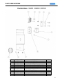
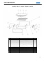
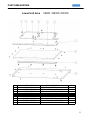
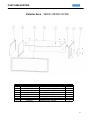
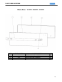
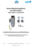
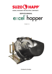
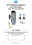
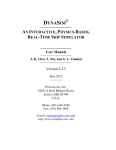
Service
Manual
This manual is to be used by qualified appliance technicians only. VIKING
does not assume any responsibility for property damage or personal injury
for improper service procedures done by an unqualified person.
This Base Manual covers general and
specific information including, but not
limited to the following models:
VEWD173
VEWD103
VEWD163
DEWD102
DFWD171
DFWD101
SMC-0016
April 2010
Safety Information
SAVE THESE INSTRUCTIONS
REVIEW ALL SERVICE INFORMATION IN THE APPROPRIATE SERVICE MANUAL AND TECHNICAL SHEETS
BEFORE BEGINNING REPAIRS.
Pride and workmanship go into every product to provide our customers with quality appliances. It is possible,
however, that during the lifetime of a product service maybe require. Products should be serviced only by a qualified
authorized service technician who is familiar with the safety procedures required to perform the repair and is equipped
with the proper tools, parts, testing instruments, and the appropriate service manual.
Safety Information
We have provided many important safety messages
throughout this manual and on the product. Always
read and obey all safety statements. To properly
identify a safety statements look for the following
safety alert symbol.
This symbol alerts personnel to hazards that can
many different types of altering messages. All safety
messages will be preceded by a safety alert symbol
and the word “DANGER”, “WARNING”or
“CAUTION”.
DANGER
Immediate hazards which WILL result in severe
personal injury or death.
All safety messages will identify the hazard, tell you
how to reduce the chance of injury, and inform you
what can happen if the instructions are not followed.
WARNING
To avoid risk of serious injury or death, repairs
should not be attempted by unauthorized
personnel.
CAUTION
VIKING will not be responsible for any injury or
property damage from improper service
procedures. If performing service on your own
product, you must assume responsibility for any
personal injury or property damage which may
result.
WARNING
Hazards or unsafe practices which COULD result
in severe personal injury or death.
CAUTION
Hazards or unsafe practices which COULD result
in minor personal injury, product or property
damage.
2
Table of Contents
Description
Page
GENERAL INFORMATION
Safety Information… … … … … … ......................
Table of Contents… … … … … … .....................
2
3
DISASSEMBLY
Control Location and access … .… … … … ........ 4
Terminal Block and Control access … … .… ..... 5
Drawer removal … .......… … … … … … … … .… .. 6
Thermostat and heating element location.....… .. 7
Model and Serial location… … … … … … … … … … 7
Element and Thermostat removal… … … … … … .. 8
ELECTRICAL
Wiring Diagram… … … … … … … … … … … … … … . 9
PARTS BREAKDOWNS
Control Area ....................................................
Drawer Area ....................................................
Lower Unit Area ..............................................
Exterior Area ...................................................
Door Area .......................................................
10
11
12
13
14
3
DISASSEMBLY
VEWD / DEWD / DFWD – Warming Drawer
The 30" Built-In warming drawer is shown below (FIG 1) with the front door assembly removed. When the
drawer is extended out you will have access to the temperature control (FIG 2 inset)
FIG 1
FIG 2
The temperature range of the warming draw er is between 90° F (Min) to 250"F (Max) The
temperature is control by the thermostat. In order to gain access to the thermostat and power
connections, removed the unit from the cabinet to expose the right side access panel. FIG 3
shows the cover inst alled (Outlined with dotted red line)
FIG 3
FIG 4
Romex cable
inlet
Remove the 3 Phillips Head screws to access the main terminal block . In FIG 3 we see the
opening in the rear of the warming draw er for the Romex power supply line (Supplied by
electrician).
4
DISASSEMBLY
With the side panel removed, access to the main terminal block is possible. FIG 5 shows the main
terminal block. The Romex cable is feed through the cable hold down clamp (Circled), and then
the power connections are made at the terminal block.
FIG 5
Line Ground Neutral
FIG 6 shows the Component compartment where the thermostat control is housed. The Capillary
tube of the thermostat is routed through the side wall to the sensor. In this same location is where
the heating element connections are located. One side is wired directly to Neutral. The other to
the Thermostat. The indicator lamp is directly above the thermostat (Not shown)
FIG 6
Thermostat
connections
Thermostat
bulb
Heating
Element
connections
5
DISASSEMBLY
To gain access to the heating element and thermostat sensor bulb, it will be necessary to remove
the draw assemb ly. With draw er fully extended, release the draw by lifting up on the locking tabs
(one on each side) FIG 7 shows the location of the locking tabs.
FIG 7
Lift up on
each side
FIG 8 shows the draw being lifted away from the drawer tracks. Remove and place on a protected surface.
FIG 8
6
DISASSEMBLY
With the drawer removed we now have access to the thermostat bulb and heating element. FIG 9 shows the
location of the Model and Serial number location, thermostat senor bulb and the left and right rear door catch
assemblies (Circled in red).
FIG 9
Door Catch
Door Catch
Draw track LT
Draw track RT
Thermostat
bulb
Thermostat
bulb
Model / Serial
information
Model – Serial
location
Fig 10 shows a close-up of the thermostat cap tube routed through the hold down clamp and the senor bulb in
its mounting bracket.
FIG 10
Capillary tube hold
down clamp
Thermostat bulb
mounting bracket
7
DISASSEMBLY
In order to remove and replace the heating element, you will need to remove (10) Phillips head screws. Each
hold down bracket shown in FIG 11 (Circled in Red) is held in place with (2) screws each.
FIG 11
FIG 12 shows the right side entrance where the thermostat and heating element enter the
chamber of the warming drawer. Remove the (2) screws shown to pull the heating element from the unit.
FIG 12
8
WIRING DIAGRAM
WIRING DIAGRAM - VEWD / DEWD / DFWD
Heating Element
Volts:
120
Amps:
4
Watts: 475
Ohms: 30.3
Supply Voltage
120
Thermostat
90° - 250° Fahrenheit
9
PARTS BREAKDOWN
Control Area VEWD / DEWD / DFWD
ITEM
1
2
3
4
5
6
7
8
9
10
11
PART NUMBER
PE070147
NON SERVICEABLE
NON SERVICEABLE
NON SERVICEABLE
A1002457
NON SERVICEABLE
NON SERVICEABLE
PB010167
021270-000
017211-000
020766-000
PART DESCRIPTION
TERMINAL BLOCK (VDSC)
10 X 1 PH. HD. PAN HD. SMS
10 X 1/2 PAN PH. TEK ZINC
POWER CORD MOUNTING BRKT (VDSC)
POWER CORD MOUNTING STRAP (VDSC)
DISGN WD TSTAT SPACER (DEWD170/100)
6-32 X 3/8" PHILL PAN MS
THERMOSTAT - (VEWD)
DEWD102 CONTROL PANEL
INDICATOR LIGHT XL SNAP IN CLEAR LIGHT
DESIGNER WD KNOB
QTY
1
4
4
1
1
1
1
1
1
1
1
10
PARTS BREAKDOWN
Drawer Area VEWD / DEWD / DFWD
ITEM
1
2
3
4
5
6
7
8
9
10
11
12
13
14
PART NUMBER
NON SERVICEABLE
NON SERVICEABLE
NON SERVICEABLE
020945-000
NON SERVICEABLE
PC020022
NON SERVICEABLE
NON SERVICEABLE
NON SERVICEABLE
NON SERVICEABLE
01589-000
B20016091
NON SERVICEABLE
PC040019
PART DESCRIPTION
30" I/S TOP PANEL VEWD103
DRAWER STOP 27"
10 X 1/2 PAN PH. TEK ZINC
FRONT RACK - 30" (VEWD)
REAR INSIDE PANEL - 30" (VEWD)
WARMING DRAWER SLIDES
10 X 3/8 GREEN GROUNDING SCREW
RH INNER WALL VEWD
6-32 HEX NUT
6-32 X 3/8" PHILL PAN MS
WARMING DRAWER 30" ASM
GASKET FRAME (VEWD103)
LH INNER WALL VEWD
POP RIVET ( 0.125 GR X 0.156 DIA )
QTY
1
1
23
2
1
1
1
1
8
8
1
1
1
8
11
PARTS BREAKDOWN
Lower Unit Area
1
2
3
4
5
6
7
8
9
10
NON SERVICEABLE
PJ010009
NON SERVICEABLE
NON SERVICEABLE
021274-000
NON SERVICEABLE
NON SERVICEABLE
NON SERVICEABLE
NON SERVICEABLE
NON SERVICEABLE
VEWD / DEWD / DFWD
10 X 1/2 PAN PH. TEK ZINC
ELEMENT - 30" (VEWD)
WIRE CLAMP
THERMAL BULB BRKT (VEWD)
WD Finger Stopper
ELEMENT BRACKET (VEWD)
BRACKET (VEWD)
BOTTOM INSIDE PANEL - 30" (VEWD)
30"" WARMING DRAWER BRKT
30" WARMING DRAWER BOTTOM AL
45
1
1
1
1
4
1
1
1
1
12
PARTS BREAKDOWN
Exterior Area
ITEM
1
2
3
4
5
6
7
8
PART NUMBER
015044-000
NON SERVICEABLE
015890-000
NON SERVICEABLE
NON SERVICEABLE
PD040005
021273-000
A1004135
VEWD / DEWD / DFWD
PART DESCRIPTION
LH OUTER SIDE PANEL (DEWD102)
LH INNER WALL VEWD
WARMING DRAWER FRAME
30" OUTER TOP PANEL VEWD103
10 X 1/2 PAN PH. TEK ZINC
SNAP BUSHING - 7/8"
RH OUTER SIDE PANEL (DEWD102)
ACCESS PLATE (VEWD)
QTY
1
1
1
1
13
1
1
1
13
PARTS BREAKDOWN
Door Area VEWD / DEWD / DFWD
ITEM
1
2
3
4
PART NUMBER
N/A
N/A
N/A
PE050023
PART DESCRIPTION
SEE IPL FOR PART NUMBERS
SEE IPL FOR PART NUMBERS
SEE IPL FOR PART NUMBERS
INDICATOR LITE
QTY
1
1
1
1
14