1
DC
OPERATION
AND
SERVICE MANUAL
ELECTRONICS, INC.
60003- 07
1105 HAMILTON COURT
MENLO PARK, CA 94025
3 April 1998
Revise d
{650} 322-0711
1
ELECTRONICS, INC.
1105 HAMIL TON COURT •
MENLO PARK
•
CALIFORNIA • 94025
650-322-0711 • 800-548-6305 OUTSIDE CALIFORNIA • FAX 650-326-1993
CERTIFICATION
Rod-L Electronics, Inc. certifies that this instrument was thoroughly
inspected and tested and found to meet its published specifications
when it was shipped from the factory.
WARRANTY AND ASSISTANCE
This Rod-L Electronics, Inc. instrument is warranted against defects
in materials and workmanship for 5 years following date of delivery.
Rod-L Electronics, Inc. will repair or replace this instrument (at our
discretion) if proven to be defective during the warranty period
provided it is returned to Rod-L Electronics, Inc.
Rod-L Electronics, Inc. recommends that this instrument be
calibrated on a 6-month cycle. Under no circumstance should a 12month cycle be exceeded. This warranty remains valid providing
calibration is performed at least once every 12 months by Rod-L
Electronics, Inc. This warranty is nontransferable and is offered
solely to the purchaser.
'
This warranty is void if the instrument has been changed, modified, or
otherwise altered without the expressed permission of Rod-L
Electronics, Inc.
Rod-L Electronics, Inc. is not liable for
consequential damages. No other warranty is expressed or implied.
Returned Material Authorization must be obtained from Rod-L
Electronics, Inc. before returning this instrument for warranty repair.
Transportation costs for return of defective instrument for warranty
repair must be prepaid . and borne by the customer. Rod-L
Electronics, Inc. will assume the cost of transportation when
returning Warranty Repaired Equipment to the customer. Such
method . of transportation shall be at the discretion of Rod-L
Electronics, Inc.
Section
6
Page
Bills of Materia ls, Schemat ics, Diagram s
BOMs for Assy' s . . . . . . . . . . . . . . . . . . . . . . . . . . . . . . . . . . . . . .
Wiring Diagram s, Assembly Prints, and Schemat ics
for all PCBs (in same order as BOMs) ........ ....
44
78
List of Figures and Tables
Table 1-1
Figure 2-1
Figure 2-2
Table 2-1
Figure 3-1
Figure 3-2
Figure 3-3
Figure 3-4
Figure 3-5
Table 4-1
DC Hipot Tester Specific ations ...... .
MlOODC Front Panel Controls ........ . .
MlOODC Rear Panel Controls ........ .. .
Factory Settings . . . . . . . . . . . . . . . . . . . . .
Instrume nt Function al Block Diagram ..
HV Generato r Function s . . . . . . . . . . . . . . .
HV Control Function s . . . . . . . . . . . . . . . . .
DC Hipot Test Times . . . . . . . . . . . . . . . . . .
General Control Function s ........ ... .
Fault Location Chart . . . . . . . . . . . . . . . . .
5
8
11
12
14
20
21
21
24
25
34
Section 1
INTRODUCTION
1-1.
Scope of This Manual
This publica tion provides operatin g and servicin g instruct ions
for the Rod-L Electro nics, Inc. Models MlOODC, M120DC, and M130DC
Hipot Test Instrum ents. It is divided into six sections .
Section
Section
Section
Section
Section
Section
1-2.
1
2
3
4
5
6
Introduc tion (capabi lities and specific ations)
Installa tion and Operatio n
Theory of Operatio n
Maintena nce and Service
Options
Parts Lists, Schemat ics and Diagrams
DC Hipot Tester General Descrip tion and Test Features
The Rod-L DC Hipot Test Instrum ents are essentia lly the same.
The MlOODC is the base model, and all the controls for the M120DC
are on the front panel.
All are rugged, self-con tained testers
designed for producti on and/or laborato ry use.
The DC Hipot
Tester's purpose is to provide a means for evaluati ng the dielect ric
withstan d capabil ities of electric and/or electron ic devices when
subjecte d to abnorma lly high input voltage s.
This is accompl ished
by monitori ng for "breakdo wn" in the form of arcing/c orona or
exceedin g of the maximum allowab le current, determin ed by the
position ing of "Curren t Trip Potentio meters."
The DC Hipot Testers perform a DC High Voltage leakage and
breakdow n dielect ric withstan d test.
They test and display DC
current and voltage. Specific ations are given in Table 1-1.
These models also conduct a low current Ground Continu ity Test
concurr ent with the Hipot Test to ensure that the Device Under Test
(DUT) is capable of effectiv ely shunting the "leakage " current
produced by the high voltage to earth ground.
For operator safety,
this CHASSIS GROUND SENSE connecti on must be made with a low
resistan ce return on the DUT.
Without this connecti on, the tester
cannot enter the READY state. Both the Chassis Ground and the power
cord Safety Ground
of the DUT are monitore d
and stressed
electron ically.
If either ground fails during the test, the Hipot
Tester automat ically goes into failure mode; i.e., high voltage is
shut down and there is a visual and audible alarm.
NOTE:
The CHASSIS GROUND SENSE circuit is intended to act as a safety
ground and ground continu ity test for devices employin g a
chassis ground plane.
For testing of two-wire devices or
6
three-w ire devices that are exempted by the pertinen t
regulato ry
agency
from
perform ing
a
chassis
ground
continu ity test, the CHASSIS GROUND SENSE connecti on can be
made to either Pin 2 of he rear panel high voltage connecto r
or to any appropr iate hi pot chassis point (e.g., handle,
screw, etc.)
Connect ion of the OUT to the Hipot Tester is made via the
front panel High Voltage Recepta cle (DUT's that termina te in a three
prong cord) or the rear panel High Voltage Connect or (all others.)
All models incorpo rate a rapid, automat ic electron ic shutdown
circuit to turn off the high voltage within 2ms (two millisec onds)
after a fault.
To prevent turn-on surges, the high voltage has an
electron ically controll ed rate-of -rise (adjusta ble from 50V/sec to
5000V/s ec.)
7
1-3.
Product Specifica tions (Table 1-1)
Table 1-1: DC Hipot Tester specificat ions
Test Current
40 microampe res (µA)
full scale (F.S.)
to
10
Test Voltage
User specified up to 5000
voe
milliampe res (mA)
Voltage Rate of Rise
50 V/second to 5000 V/second (adjustabl e)
High Voltage Test Time
1 second to 90 seconds (adjustabl e)
High Voltage Shutdown
Within 2 millisecon ds after a fault or end of
test is detected (electron ic shut down circuits)
Initial Turn-On Period
Requires 2 seconds normally for
test before starting Hipot test
Safety Ground Continuity
Reject level:
0.1 to 0.5D,
safety ground
(adjustabl e) ±0.0lQ
Accuracy (Current and Voltage Monitoring )
Better than 1%
Resolutio n (Output Voltage Control)
2.5V
Resolutio n (Output Current)
4 Microampe res (µA)
Input Power
115/230 VAC, 44-66 Hz., 360 watts, max
Ripple
1% at full load, 0.05% at zero current
Regulatio n
0.05% at full load
Environme ntal Operating Temperatu re
0° to 50° c, 32° to 122° F
Exterior Color
Mint grey and Olive Grey or Black
Weight
24 lbs (10.9 kg) net, 29 lbs (13.15 kg) shipping
Dimension s
16.75 x 13.25 x 5.5 inches (43 x 34 x 14 cm)
8
1-4.
safety Featur es
A)
''Chass is Ground Sense'' - Safety ground require d to begin a
test
B)
Loss of safety ground termin ates test cycle
C)
Front panel recept acle accepts 3-prong ed power cord from
DUT provid ing maximum safety and signif icantly reduce s
time require d to perform the test
D)
Recess ed START button
E)
Visual alarm at failure
F)
Audibl e alarm at failure (contin uous tone)
G)
Fast electro nic shut down of DC High Voltag e
H)
Hard RESET after failure require d to perform next test
I)
1-5.
Visual ly display ed Program ming of DC Curren t Trip Point
and High Voltag e
J)
Adjust able, linear Ramp Up of High Voltag e
K)
Comple te discha rge of Device Under Test (DUT)
L)
High Voltag e output closed to Ground when not in test
supplie d Equipm ent
A)
DC Hipot Test Instrum ent
B)
Power Cord, three pronge d, 6 ft
C)
Chassi s Ground Sense cable, 3 ft
D)
Kit for HV connec tor mate
E)
Operat ion/Se rvice Manual
F)
Extra fuse set for the alterna te AC supply voltag e
9
Section 2
INSTALLATIO N AND OPERATION
'•
The exclamation point within a
triangle is intended to tell the
user that important operating
and servicing instructions are
in the papers that are provided
with the equipment.
WARNING
Verify that the voltage selector switch is
positioned and the correct power supply cord is
selected to match the voltage source.
WARNING
This product is shipped with a high voltage
mating plug and hole cover installed on the rear
panel HV OUT/INTERFACE connector. To reduce the
risk of shock, this plug and cover must be used
whenever the high voltage interface cable is not
installed.
In addition, the high voltage interface cable
must only be used when both ends are terminated
at their respective equipment connectors.
To
reduce the risk of electric shock, the equipment
must
not
be
operated
with
one
end
not
terminated.
2-1.
General Information
This
section
contains
the
recommended
unpacking, inspection, installation , and operation.
2-2.
procedures
for
unpacking and Inspection
Retain the shipping carton and the padding material.
Rod-L
Electronics may assess a charge for a new shipping container if an
instrument is not received in the original container.
A shipping carton that appears damaged should be inspected and
unpacked with the carrier's agent present.
Inspect the instrument
for damage (scratches, dents, broken knobs or meters, etc.)
10
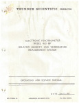
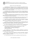
Figure 2-l:
.0
M100DC
l
b
3
6
0
0
0
0
5
7
MlOODC Front Panel Controls
IVlolVI
11
9
18
~
Alarm
V-SET lamp
emits audible signal on failure
on when V-SET switch is in set position
off when V-SET switch is in run position
3.
READY lamp
on when ready to begin Hipot Test
4.
I-SET lamp
on when I-SET switch is in set position
off when I-SET switch is in run position
5.
TESTING lamp
on during DC Hipot Test
6.
AC lamp
on when AC/DC switch is in AC position
7.
FAIL lamp
on if DC Hipot Test fails
8.
current meter
indicates current in DC mA (µA with Option 09);
inactive during AC Hipot Test;
indicates fail point when in I-SET mode
9.
HV ON lamp
flashes when 40VDC or more is present;
inactive during AC Hipot Test
10.
Voltage meter
indicates volts in DC kV; inactive for AC test;
indicates max DC kilovolts when in V-SET mode
HV output Block for input to DDT where DC or AC HV is applied
11.
receptacle
1
12.
LinePower switch turns on and indicates line power input
13.
START switch
initiates DC (or AC) Hipot Test if READY
14.
RESET button
resets Hipot
15.
DC/AC switch
chooses DC Hipot or the input from AC Hipot
16.
A/B switch
chooses A or B Ramp Rate and Test Time
17.* Select switch
(*Optional) chooses different parameter sets
18.
Chassis Ground for DDT chassis ground connection
Sense jack
1.
2•
If the instrument is found to be damaged upon receipt, notify
the carrier and Rod-L Electronics immediately.
2-3.
Installation
The Rod-L DC Hipot Test Instruments are suitable for either
bench or rack mounting.
To rack mount the instrument, use Option
15A.
The instructions for rack mounting are on page 39.
11
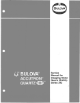
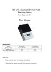
Figure 2-2:
MlOODC Rear Panel Controls
~\1&20
?•·•·}·
test . rise
0000
33 34 35 36
AC Fuses
Fl/F2 3A @ 115VAC, l.5A @ 230VAC
20. Voltage
chooses 115VAC or 230VAC input;
Selector Switch
be sure to install correct fuses
AC line power in receptacle
21.
22. HV In connector for AC Hipot Interface
HV Out connector for Ground Tester Interface
23.
24. AC Hipot Chassis connects Gnd of DC Hipot to Gnd of AC Hipot
Gnd Sense jack
to enable AC Hipot Test to start
25. Chassis Ground
for DUT chassis ground connection
sense jack
26.* Remote connector (*Optional) for Remote Interface
27.* Hands-Off con.s
(*Optional) for Hands-off palm switches
28.
V-SET pot
for voltage programming
I-SET pot
29.
for current trip programming
30. V-SET switch
in "set" position allows voltage programming
pot to be adjusted and viewed on the voltage
meter
I-SET switch
31.
in ''set'' position allows current ''trip'' fail
point programming pot to be adjusted and
viewed on the current meter
Ground jack
32.
for connecting tester's chassis' together
"A" Test Time Adjustment potentiometer
33.
"B" Test Time Adjustment potentiometer
34.
"A" Voltage Rise (Ramp Rate) Adjustment potentiometer
3 5.
36. "B" Voltage Rise (Ramp Rate) Adjustment potentiometer
37. Burn Switch
enables DC Hipot to perform destructive test
Note that on the Ml20DC, all controls are on the Front Panel.
19.
2-4.
Power Requirements
The Rod-L DC Hipot Testers require a power source of either
115 or 230 volts AC, 44 to 66 Hz, single-phase.
Prior to applying
power to the instrument, ensure the AC line voltage selector switch
on the Rear Panel is in the appropriate position.
When using the
Rod-L Hipot with other Rod-L Testers, the Ground Sense Circuit often
works better when the Rod-L Testers are connected to a line input
with the same ground circuit.
12
2-5.
Operating Controls
The front panel and rear panel controls and indicators for the
MlOODC are shown and briefly described in Figures 2-1 and 2-2. They
would all be on the Front Panel of the Model M120DC.
2-6.
storage
It is strongly recommended that the DC Hipot be packed as if
for reshipment.
Environmenta l conditions during storage and
reshipment should be as follows:
2-7.
A)
Maximum temperature:
167°F (75°C)
B)
Minimum temperature:
-40°F (-40°C)
Repackaging for Shipment
If possible, use the original shipping container and packing
materials. Otherwise:
A)
Wrap the DC Hipot in heavy paper or plastic before placing
it in the shipping container.
B)
Use plenty of packing material around the instrument, and
protect the front panel with cardboard or plastic bubble
packing.
Protect the instrument with two inch rubberized
foam pads placed along all surfaces of the instrument, or
with a layer of excelsior about 6 inches thick packed
firmly against all surfaces of the instrument.
C)
Use a strong, well-sealed shipping container
bursting test.)
D)
Mark the container "FRAGILE -
13
(350 lb/in 2
DELICATE INSTRUMENT."
WARNING
This instrum ent to be used ONLY in THREE__1URE
GR_OUNDED OUTLETS.
It is recomm ended that
period ic checks of the outlet and the ground
wire be made to ensure operato r safety .
2-8.
Initia l Instal lation and Power-u p
The Rod-L DC Hipot Tester is shipped configu red for 115 VAC
operat ion. Approp riate fuses (1.5 ampere) are also provid ed for 230
VAC operat ion.
Before applyin g 230 VAC power to the instrum ent,
ensure that the correc t fuses are install ed (see Fig. 2-2.,) then
ensure that the Voltag e Selecto r Switch on the Rear Panel is in the
correc t positio n.
CAUTION
Changi ng Fuses:
Turn off the Hipot Tester and
DISCONNECT THE POWER CORD..
Then instal l the
proper
fuses.
Otherw ise,
damage
to
the
instrum ent and/or operato r could result .
2-9.
Factory setting s
The Rod-L DC Hipot Tester is shippe d with the followi ng
factory -select ed setting s (unless otherw ise reques ted in writing by
the custom er) :
Table 2-l:
Factory Setting s
TEST MODE SWITCH
II
Voltag e
1500 VDC
1500 VDC
Maximum Curren t
5 mA
5 mA
Test (Dwell) Time
15 sec
2
Ramp Rate
200 V/sec
Input Line Voltag e Select
115 VAC
14
A II
II
B"
sec
1000 V/sec
2-10.
operational Check
is
This
an
operator
oriented
procedure
which
allows
operational check of the Rod-L DC Hipot Test Instrument without test
equipment.
Refer to Section 4 of this manual for a complete
calibration procedure.
Place the instrument in a sturdy position, preferably on an
insulated surface, with all surrounding metal/conduc tors grounded.
Position the power cord so as to avoid being walked on or pinched by
other equipment.
A)
Set LINE POWER switch to OFF.
B)
Validate that fuses Fl and F2 are the proper values.
C)
Verify Input Line Voltage Select switch position.
D)
Connect AC Power Cord to AC receptacle on the rear panel.
E)
Connect the AC Power Cord to a 115 VAC ±10% power source.
F)
Ensure that the V-SET and I-SET switches are in the "RUN"
position. Place the AC/DC switch in the DC position.
G)
Verify Remote/Local Switch is in Local position.
H)
Connect low current Ground Sense Cable to the CHASSIS
GROUND SENSE terminal on the front panel.
Then clip the
other end of the cable to the Hipot Tester chassis (the
handle is a convenient point.)
When Option 09 Low
Current is present, the alligator clip end has to be
connected to HV Return instead.
I)
Set LINE POWER switch to ON.
illuminate.
J)
NOTE:
The power ON lamp should
The green READY lamp should illuminate.
If the lamp in the power switch remains off, check for proper
AC line voltage.
If the lamp in the power switch is ON and the
green READY lamp remains off, check the CHASSIS GROUND SENSE
connections.
K)
With the READY lamp lit, push the START switch. The HV ON
lamp will begin flashing.
While the HV ON lamp is
flashing, quickly disconnect the CHASSIS GROUND SENSE
cable.
The FAIL lamp should 1 ight and the alarm sound,
indicating a Safety Ground failure.
15
WARNING
DC high voltag e is prese nt at the front panel HV
recep tacle block and the rear panel cylind rical
conne ctor when the HV ON lamp flashe s.
2-11.
L)
Push the RESET switch to exting uish the FAIL lamp and the
alarm.
M)
Recon nect the CHASSIS GROUND SENSE cable per step "H."
The READY lamp should re-illu minat e.
N)
Push START.
The HV ON lamp will begin flashi ng and the
OUTPUT VOLTAGE meter will indic ate the contro lled rise to
the prese t voltag e. The HV ON light will remain flashi ng
until the test time has expire d or a test failur e is
detec ted.
Fail Indic ations
Over curren t failur es are repres ented with the FAIL lamp
audib le alarm coming on contin uously unti 1 the RESET button and
is
presse d.
Ground Conti nuity faults are also depic ted with the FAIL
and audib le alarm coming on contin uousl y, and additi onally lamp
READY lamp turns off. The Hipot Teste r must be manua lly RESET , the
.
An Under Curre nt FAIL is indica ted with a tone that is about
one second long, then the Hipot Teste r resets itself .
Option 05 Hands -Off FAIL signa l is about two second s long, and
then the Hipot Teste r resets itself autom atical ly.
Option 20 Ohm Sense FAIL emits beeps at about 1 to 2 per
second until the reset button is pushed . Also, there are no
TESTING
nor FAIL lights . This does not denote failur e.
When Option 10 Audib le Test Tone
Teste r, the alarm will sound pulses at
whene ver a TEST is in progr ess.
2-12.
is instal led in a Hipot
3 to 6 beeps per second
set curren t Fail Point
When the I-SET switch is in the "set" positi on, adjus
I dial on the rear panel until the desire d settin g is indica t the
ted on
the curren t meter [CW (clock wise) to increa se.]
2-13.
Prese t Test Voltag e
With the V-SET switch in the "set" positi on, adjus t the V dial
to the desire d settin g (CW to increa se.)
Be sure to return the SET switch es to the RUN positi on.
16
2-14.
Prese t Test Time/ Rise Time
With the A/B switch in the A positi on, the A Test Time Pot can
be adjus ted (CW to increa se.)
A TEST must be in progr ess to adjus t
for desire d Ramp Rate (rate of rise to full voltag e.)
Remem ber,
increa sing the time will decrea se the Ramp Rate.
The "A" test time pot is used to adjus t for desire d dwell time
at full voltag e.
These adjust ments may reqire starti ng the TEST
sever al times .
The
positi on.
2-15.
"B"
times
are
adjust ed
with
the
A/B
switch
in
the
B
Autom atic Test Proced ure
Conne ct the Device Under Test (OUT) to the Hipot Teste r outpu
t
voltag e recep tacle.
Then conne ct the Chass is Ground Cable betwee n
the DC Hipot Teste r and an elect rical ground of the OUT.
If
READY light goes on a solid ground conne ction is sensed and the
the
testin g may procee d; if the READY light does not go on, the
ground
needs check ing.
When the READY light comes on, the OUT is ready to be hipot
tested with the START signa l coming from the REMOTE or the
START
switch .
NOTE:
If the DC Hi pot Tester is opera ted at maximu m voltag e and
maximu m curre nt simult aneou sly, then the opera tion duty
cycle
must not exceed 25%--w here duty cycle shall be define d as:
opera tion time
opera tion time + rest time
17
x 100%
2-16.
Using the DC Hipot Tester with a Rod-L AC Hipot
See the drawin gs at the rear of this manua l, #s 01076 -01,
01077 -01, and 01076 -01. One of these drawin gs should enable
settin g
up of the DC Hipot Teste r with a Ground Conti nuity Teste r and/o
r AC
Hipot Teste r.
Ensure the Teste rs are conne cted to the same AC Line Power
source .
The Ground Teste r /Hipo t Teste r Interf ace Cable is conne cted
from the AC Hipot Teste r to the conne ctor on the Rear Panel
of
DC Hipot Teste r labele d "AC Hipot, 11 which is the input HV conne the
ctor.
This ties the high voltag e, Start, and Reset signa ls from
the
AC
Hipot Teste r, so that the DUT need be conne cted only into the
Front
Panel Recep tacle of the DC Hi pot Teste r.
Then, when the
switch is switch ed to AC, and the Start button on the DC AC/DC
Hipot
Teste r is presse d, the AC Hipot begin s a test, and the high
voltag
e
is conne cted to the Front Panel Recep tacle of the DC Hipot Teste
r.
18