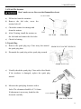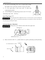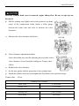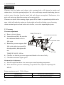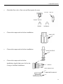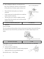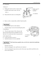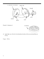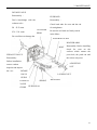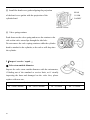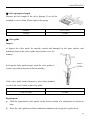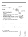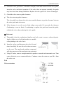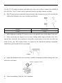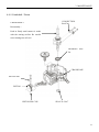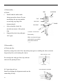
1
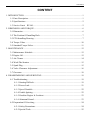
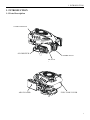
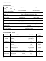
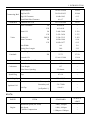
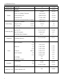
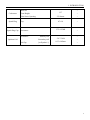
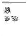
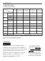
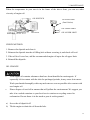
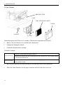
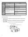
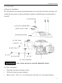
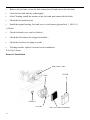
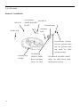
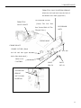
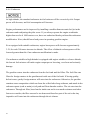
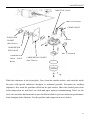
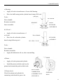
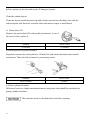
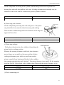
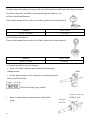
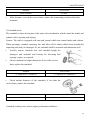
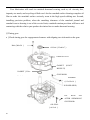
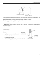
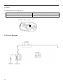
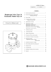
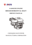
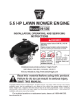
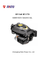
RV160 RV170 SERVICE MANUAL Chongqing Rato Power Co., Ltd CONTENT CONTENT 1. INTRODUCTION ................................................................................................................ 1 1-1 Parts Description......................................................................................................... 1 1-2 Specifications.............................................................................................................. 2 1-3 Service Limit RV160 ............................................................................................... 2 2. DIMENSION AND TORQUE ............................................................................................. 6 2-1 Dimension ................................................................................................................... 6 2-2 The Position Of Installing Hole .................................................................................. 7 2-3 PTO Installing Drawing.............................................................................................. 7 2-4 Torque Value ............................................................................................................ 10 2-5 Standard Torque Value ............................................................................................. 11 3. MAINTENANCE ............................................................................................................... 12 3-1 Maintenance Schedule .............................................................................................. 12 3-2 Engine Oil ................................................................................................................. 12 3-3 Air Cleaner ............................................................................................................... 14 3-4 Wash The Strainer .................................................................................................... 15 3-5 Spark Plug................................................................................................................. 15 3-6 Valve Clearance Adjustment .................................................................................... 16 3-7 Governor ................................................................................................................... 18 4. DISASSEMBLING AND SERVICING............................................................................. 19 4-1 Troubleshooting ........................................................................................................ 19 4-1-1 Starting Difficult ........................................................................................... 19 4-1-2 Power Lack .................................................................................................... 21 4-1-3 Speed Unstable .............................................................................................. 22 4-1-4 Unable Igniting .............................................................................................. 22 4-1-5 Gasoline Engine Is Overheat ......................................................................... 23 4-1-6 Abnormal Sound ........................................................................................... 23 4-2 Preparation Of Servicing .......................................................................................... 24 4-2-1 Safety Precautions ......................................................................................... 24 4-2-2 Special Tools ................................................................................................. 25 CONTENT 4-3 Dismounting Chart ................................................................................................... 26 4-4 Gasoline Engine ........................................................................................................ 27 4-4-1Recoil starter / fan cover ................................................................................ 27 4-4-2 Muffler .......................................................................................................... 30 4-4-3 Fuel Tank....................................................................................................... 31 4-4-4 Air Cleaner .................................................................................................... 32 4-4-5 Governor........................................................................................................ 34 4-4-6 Carburetor...................................................................................................... 36 4-4-7 Flywheel ........................................................................................................ 41 4-4-8 Cylinder Head / Valve ................................................................................... 45 4-4-9 Crankshaft / Piston ........................................................................................ 53 4-5 Electric Diagrams ..................................................................................................... 62 1. INTRODUCTION 1. INTRODUCTION 1-1 Parts Description START HANDLE OIL DIPSTICK SPARK PLUG MUFFLE R AIR CLEANER FUEL TANK COVER 1 1. INTRODUCTION 1-2 Specifications MODEL RV160 RV170 395×348×282(mm) 395×348×282(mm) 12.1Kg or 13.7kg 12.5Kg or 13.7Kg ITEM L×W×H(not including crankshaft output terminal) Dry Weight Engine Type Single Cylinder Horizontal,4-Stroke, OHV Displacement 163cc 173.2cc Bore × Stroke 68mm×45mm 70mm×45mm Theoretical Maximum Power 3.0kW/3,600r/min 3.2kW/3,600r/min Recommended Using Power 2.3Kw /3600r/min 2.4 kW/3,400r/min Maximum Torque 8.8N·m/2,500r/min 9.0N·m /2,500r/min Fuel Consumption 395g/ kw·h 395g/kw·h Cooling System Forced Air Ignition System Capacitance Discharge Type or Inductance Discharge Type PTO Shaft Rotation 1-3 Service Limit Vertical Shaft Output STANDARD SERVICE LIMIT Maximum Speed (No Load) 3400±100rpm -- Idle Speed 1900±100rpm -- 1.38Mpa/1200rpm -- PARTS Engine UNIT:mm RV160 ITEM Cylinder Compression Cylinder Head Sleeve I.D 68 68.165 Cylinder Head Warpage -- 0.10 Skirt O.D. 67.985 67.845 0.015-0.050 0.12 Piston Pin Bore I.D. 18.002-18.008 18.048 Piston Pin O.D 17.994-18.00 17.954 Piston Pin-to-Piston Pin Bore Clearance 0.002-0.014 0.08 Ring Side Clearance: second 0.030-0.065 0.15 Ring Enc Gap: second 0.2-0.4 1.0 Ring Width: second 1.5 1.37 Piston–to-Cylinder Clearance Piston Piston Rings 2 1. INTRODUCTION Connecting Rod Small End I.D 18.005-18.020 18.052 Big End I.D 30.020-30.033 30.066 0.040-0.063 0.12 0.1-0.7 1.1 29.970-29.980 29.92 IN 0.10±0.02 -- EX 0.15±0.02 -- IN 5.468-5.480 5.318 EX 5.435-5.450 5.275 IN/EX 5.500-5.512 5.562 IN 0.020-0.044 0.10 EX 0.050-0.077 0.12 Seat Width 0.8 2.0 Spring Free Length 34.0 32.5 IN 27.70 27.45 EX 27.75 27.50 13.966-13.984 13.916 14.0 14.048 Main Jet #65 -- Float Height 13.7 -- 2-5/8turns -- 0.7-0.8 -- 3.75-6.25kΩ -- Primary coil 0.8-1.0Ω -- Secondary coil 5.9-7.2kΩ -- (at flywheel) 0.4±0.2 -- STANDARD SERVICE LIMIT Maximum Speed (No Load) 3400±100rpm -- Idle Speed 1900±100rpm -- 1.38Mpa at 1200rpm -- Big Oil Clearance Small End Side Clearance Crankshaft Crankshaft Pin O.D Valve Clearance Stem O.D Valve Guide I.D Stem Clearance Cam Height Camshaft Journal O.D Crankcase Cover Camshaft Bracket I.D Carburetor Pilot Screw Opening Spark Plug Spark Plug Cap Gap Resistance Resistance Ignition Coil Air Gap RV170 PARTS Engine ITEM Cylinder Compression 3 1. INTRODUCTION Cylinder Head Sleeve I.D 72 71.165 Cylinder Head Warpage - 0.10 Skirt O.D. 69.985 69.845 0.015-0.050 0.12 Piston Pin Bore I.D. 18.002-18.008 18.048 Piston Pin O.D 17.994-18.00 17.954 Piston Pin-to-Piston Pin Bore Clearance 0.002-0.014 0.08 Ring Side Clearance: second 0.030-0.065 0.15 Ring Enc Gap: second 0.2-0.4 1.0 Ring Width: second 1.5 1.37 Small End I.D 18.005-18.020 18.052 Big End I.D 30.020-30.033 30.066 0.040-0.063 0.12 0.1-0.7 1.1 29.970-29.980 29.92 Piston–to-Cylinder Clearance Piston Piston Rings Connecting Rod Big Oil Clearance Small End Side Clearance Crankshaft Crankshaft Pin O.D IN 0.15±0.02 EX 0.20±0.02 IN 5.468-5.480 5.318 EX 5.435-5.450 5.275 IN/EX 5.500-5.512 5.562 IN 0.020-0.044 0.10 EX 0.050-0.077 0.12 Seat Width 0.8 2.0 Spring Free Length 34.0 32.5 IN 27.70 27.45 EX 27.75 27.50 13.966-13.984 13.916 14.0 14.048 Valve Clearance Stem O.D Valve Guide I.D Stem Clearance Cam Height Camshaft Journal O.D Crankcase Cover Camshaft Bracket I.D 4 1. INTRODUCTION Carburetor Main Jet #65 -- Float Height 13.7 -- 2-5/8turns -- 0.7-0.8 -- 3.75-6.25kΩ -- Pilot Screw Opening Spark Plug Spark Plug Cap Gap Resistance Resistance Ignition Coil Air Gap Primary coil 0.8-1.0 Ω Secondary coil 5.9-7.2 kΩ (at flywheel) 0.35~0.45mm ---- 5 2. DIMENSION AND TORQUE 2. DIMENSION AND TORQUE 2-1 Dimension 6 2. DIMENSION AND TORQUE 2-2 The Position Of Installing Hole 2-3 PTO Installing Drawing P1 Shaft P2 Shaft SEAT FACE SEAT FACE P1 Shaft P2轴 7 2. DIMENSION AND TORQUE P3 Shaft P26 Shaft SEAT FACE SEAT FACE P27 Schaft SEAT FACE 8 P28 Schaft SEAT FACE 2. DIMENSION AND TORQUE P29 Shaft SEAT FACE 9 2. DIMENSION AND TORQUE 2-4 Torque Value ITEMS FASTENERS TORQUE VALUE (N·m) Connection-Rod Bolt M7×1.0 12±1 Governor Gear Bolt M6×12 10±2 Crankcase Cover Bolt M8×50 26±1 M14-1.25 18±2 Cylinder Head Bolt M8×50 26±1 Rotation Shaft Bolt M8 ×1.25 24±2 Rotation Shaft Locked Nut M6 ×0.5 10±1 Cylinder Head Cover Bolt M6×12 6±1 Ventilation Chamber Cover Bolt M6×12 10±1 Side Shield Bolt M6×12 10±2 End Shield Bolt M6×16 10±2 M6×12 10±2 M6×20 10±2 Flywheel Nut(Aluminum) M14×1.5 52±4 Flywheel Nut(Cast Iron) M14×1.5 78±4 M6×25×1.0 10±2 M6×86 12±2 M6×88 12±2 Fuel Tank Support Bolt M6×12 10±2 Fuel Tank Bolt M6×14 6±2 M6 10±2 Throttle Control Sub Assemble Bolt M6×28 10±2 Air Cleaner Nut M6×1.0 10±2 Governor Support Nut M6×1.0 6±1 Muffler Support Bolt M6×12 10±2 Muffler Bolt M6×80 10±2 Muffler Cover Bolt M6×12 10±2 Engine Cover Bolt M5×16 6±1 M10 ×1.25 15-20(18) Spark Plug Brake Bolt Ignition Wire Bolt Stud Recoil Starter Reel Nut Drain Plug For unspecified bolt, screw and nut, refer to the standard torque value. 10 2. DIMENSION AND TORQUE 2-5 Standard Torque Value FASTENERS Bolt, Nut SPECIFICATION TORQUE VALUE(N·m) 5mm Bolt, Nut 4.5-6 6mm Bolt, Nut 8-12 8mm Bolt, Nut 18-25 10mm Bolt, Nut 29-34 12mm Bolt, Nut 49-59 4mm Screw 1.5-2.6 5mm Screw 3.5-5 6mm Screw 7-11 5mm Flange Bolt 3.6-6.9 6mm Screw 7-11 5mm Flange Bolt 3.6-6.9 6mm Flange Bolt 10-14 8mm Flange Bolt 20-26 10mm Flange Bolt 35-45 11 3. MAINTENANCE 3. MAINTENANCE 3-1 Maintenance Schedule FREQUENCY ITEM Engine Oil Oil Level Check EVERY 6 EACH FIRST MONTH EACH SEASON EACH YEAR MONTH OR 100 TIME OR 20 HRS OR 50 HRS OR 300 HRS HRS √ √ Replace Air Cleaner Oil Alert System Spark Plug Oil Strainer Valve Check √ √ √ Clean Replace Check √ Clean, Adjust √ Replace √ Clean √ Check-Adjust √* Cylinder Head Clean √* Fuel Tank Replace Clearance Every three years *These items should be serviced by company authorized dealer, unless you have the proper tools and mechanically proficient. 3-2 Engine Oil ● Engine oil is a key factor in deciding the engine’s performance. Do not apply engine oil with additives or 2-stroke gasoline engine oil, because they haven’t enough lubrication, and may shorten the engines service life. ● Check the engine with it stopped on a level ground. ● Engine oil capacity: RV160 & RV170 0.6L Engine oil recommended: SAE 10W-30 12 3. MAINTENANCE When the temperature in your area is in the frame of the above chart, you can use other viscosity of engine oil. OIL DIPSTICK SEALING RING (Don’t Refuse) OIL UPPER LIMIT OIL HOLE OIL LOWER LIMIT CHECK METHOD 1. Remove the dipstick and clean it. 2. Reinsert the dipstick into the oil filling hole without screwing it, and check oil level. 3. If the oil level is too low, add the recommended engine oil up to the oil upper limit. 4. Reinstall the dipstick. OIL CHANGE Used engine oil contains substances that have been identified as carcinogenic. If repeatedly left in contact with the skin for prolonged periods, it may cause skin cancer. Wash your hands thoroughly with soap and water as soon as possible after contact with used engine oil. Please dispose of used oil in manner that will pollute the environment. We suggest you take it in a sealed container to your local service station or recycling center for reclamation. Do not throw it in the trash or pour it on the ground. a) Screw the oil dipstick off. b) Tilt the engine to drain the oil from the hole. 13 3. MAINTENANCE 3-3 Air Cleaner BREATHE TUBE CASE AIR CLEANER ELEMENT COVER GASKET NUT M6 Wash the engine each 50 hrs (or 3 months). (Wash more frequently in dust area) Remove the air cleaner cover and take the element out. Change the damaged element. Clean the element before reusing. Clean the element: Wash the element with detergent and dry it. Foam Element Paper Element Immerse the element into the oil and squeeze the excessive oil. The element should be wet, but not drop the oil. Blow the compressed air from the inner side or lightly tap to move the dust. If dirty badly, replace in time. Be careful to prevent dirt from entering the air duct that leads to the carburetor. Place the foam element over the paper element, and cover the case cover on. 14 3. MAINTENANCE 3-4 Wash The Strainer Don’t smoke or use fire near the flammable solvent. FUEL TANK a) Fill the fuel into the container b) Remove the fuel tube, screw the strainer bolt off. c) Check the strainer for damage and clean the strainer. CLIP d) After Cleaning, install the strainer on OIL TUBE STRAINER the fuel tank and connect the fuel tube. e) Check for leaking. 3-5 Spark Plug a) Remove the spark plug cap. Clear away dirt around SPARK PLUG SOCKET WRENCH the spark plug base b) Dismantle the spark plug with a spark plug wrench. SPARK PLUG CAP c) Visually check the spark plug. Clean with a Steel brush. If the insulator is damaged, replace the spark plug instead. d) Measure the spark plug clearance with a feeler. The clearance should be 0.7~0.8mm. If adjustment is necessary, bend the side 0.70~0.80mm electrode carefully. SIDE ELECTRODE 15 3. MAINTENANCE e) To avoid cross-threading, first, screw in spark plug by hand, then tighten with a spark plug wrench to compress the gasket. f) If a new spark plug is used, more twist 1/2 turns after compressing the gasket. g) If reinstalling the used spark plug, just more twist 1/8-1/4 turns. Spark plug torque value:18±2N·m Spark Plug Type:F7TC The spark plug must be tightened securely, or it may become very hot to damage the engine. Only use recommended spark plug or the equivalent. Incorrect heat range of the spark plug may damage the engine. 3-6 Valve Clearance Adjustment Measure the valve clearance in the cold of the engine state. SPARK PLUG SPARK PLUG CAP a) Remove the bolt(M6×12), cylinder head cover, gasket, spark plug cap and spark plug. GASKET CYLINDER HEAD COVER BOLT M6×12 16 3. MAINTENANCE After the cylinder head cover is removed, engine oilmay flow. Be sure to wipe up any flowed oil. b) Pull the starting rope lightly and set the piston at top dead center of the compression stroke (Insert a feeler gauge between the rocker arm and valve to measure the valve clearance). c) Measure the valve clearance with feeler. FEELER d) Valve clearance adjustment method: Loose the locking nut, turn the adjusting nut to get the correct valve clearance. Screw down the locking nut. Torque value: 10N.m e) Recheck the valve clearance f) Set the new gasket with the projection of the cylinder head g) Install the cylinder head cover and tighten the four bolts to the specified torque. Torque value :6N.m Standard Valve Clearance Intake Valve 0.10±0.02mm Exhaust Valve 0.15±0.02mm Adjusting Nut Value Clearance Screw Down Decreasing Screw Off Increasing 17 3. MAINTENANCE Clearance too big: Intake and exhaust valve opening delay will shorten the intake and exhaust time, lower the opening height of the valve and change normal distributing phase to result in power lowering from the intake lack and exhaust uncompleted. Furthermore, also make vale train parts knock increasing and wearing quickly. Clearance too small: After running, engine parts will be heated to expand and push the valve open, which will make the engine not closing tight and result in leaking, power lowering, serious carbon deposit or burn on the valve surface, even valve impacting the piston. 3-7 Governor Governor adjustment a) Remove the air cleaner. b) Loosen the nut (M6). Be sure that THROTTLE VALVE GOVERNOR SUPPORT the carburetor throttle valve is GOVERNOR ARM fully open. c) Rotate the governor support shaft fully to the right (governor fully closed position), and tighten the nut. NUT M6 TORQUE VALUE: 10N.m d) Check to see that the governor support and throttle valve move freely. e) Check the maximum engine speed Maximum Speed Adjustment a) Start the engine and allow it to warm up to normal operating temperature. b) If the maximum speed not conforming to specified value, adjust the adjusting bolt M5×30. Engine maximum speed:3400±100rpm 18 Speed too big Turn the bolt counterclockwise. Speed too small Turn the bolt clockwise 3. MAINTENANCE 4. DISASSEMBLING AND SERVICING 4-1 Troubleshooting 4-1-1 Starting Difficult Spark plug is in bad conditions Fuel supply is normal. Fuel supply is not smooth or no fuel supply. CAUSE Normal spark plug Something wrong with the fuel system. Normal high –tension line spark. High-tension line no spark Normal spark plug spark Normal fuel supply system. Normal cylinder compression TROUBLE REMEDY There is no enough fuel in fuel tank and fuel cock is closed. Fill fuel, open fuel cock. Air vent in the fuel filler cap is clogged Dredge air vent. Improper or clogged main oil flow hole. Readjust or clean, blow to get through. Needle valve is not closed properly or start hole is clogged. Dismantle needle valve and repair, clean, blow to get through. Float is damaged or sticking. Repair float Fuel is too filthy or deteriorated Replace There is water in fuel. Replace Too much fuel in engine Drain extra fuel, dry up spark plug electrodes. Wrong fuel brand Select proper fuel brand corresponding with the requirements. Too much carbon deposit and dirt around electrodes. Clear away. Electrodes are burn damaged seriously or insulators damaged. Replace spark plug. Improper electrodes gap. Adjust to proper value. High –tension line is damaged. Replace Ignition coil is damaged. Replace Magneto loses magnetism. Replace Abnormal gap between the ignition coil and flywheel. Adjust gap 19 Normal spark plug. Normal fuel supply system. Abnormal cylinder compression. TROUBLE CAUSE REMEDY Piston ring is worn to or even over its wear limit Replace Piston ring is broken. Replace Piston ring is sticking. Clear up carbon fouling. Spark plug is not installed tighten or without a gasket. Tighten with a gasket in. Air leakage between cylinder block and cylinder head. Air leakage in the valves Check cylinder gasket, and the flatness of the surface by which cylinder block contacting with cylinder head Tighten cylinder head bolts in stipulated order to stipulated torque. Check valve. Clearance and tightness, repair if necessary. If still can’t starting, have the engine to our authorized dealer for repairing. ● Spark plug testing Make sure there is no spilled fuel outside the engine and that the spark plug isn’t dipped with fuel. When testing the spark plug, never hold the high- tension line of the spark plug with wet hand. To prevent fire, keep sparks far away from the spark plug mounting hole. RECOIL STARTER GRIP SPARK PLUG, SPARK PLUG CAP 20 3. MAINTENANCE Turn the fuel cock to “OFF” position, and drain the gasoline of the carburetor. Remove the spark plug and spark plug cap Pull the recoil starter grip to drain the gas in the cylinder. Install the spark plug cap. Put the control lever to “low” position. Pass negative pole (thread) of the spark plug through cylinder cover to connect grounding and pull the recoil starter grip to observe the spark. 4-1-2 Power Lack Ignition System Fuel Supply System CAUSE Poor Compression When increasing the throttle, speed increase slow or even decrease and stop running TROUBLE REMEDY Air in fuel line or fuel line clogged. Exhaust air or dredge fuel line Main oil flow hole is not adjusted properly. Readjust In carburetor, needle valve hole and main oil flow hole clogged. Clean and blow to get through Fuel cock is clogged up. Clean, replace damaged part Too much carbon deposit in combusting chamber. Clear away Too much car bon fouling in muffler and exhaust pipe. Clear away Air cleaner is clogged up. Clean air cleaner filter element Intake pipe is leaking. Repair or replace Piston or cylinder or piston ring is worn Replace the worn Air leakage from the surface by which cylinder Replace cylinder gasket block contacting with cylinder head. Too big or too small valve clearance. Readjust Valve tightness is poor. Repair Drain the oil of the fuel tank out. Drain the gasoline by loosening the oil drain bolt of the CYLINDER PRESSURE METER carburetor. Remove the spark plug cap and spark plug and install the cylinder pressure meter. Forcibly pull the recoil starter several times and measure compression force. (Compression Force:1.38Mpa/1200rpm) 21 4-1-3 Speed Unstable TROUBLE CAUSE Knocking Sound Abnormal Combustion Spark Lacking REMEDY Piston, cylinder or piston ring is worn excessively. Replace the worn Piston pin and piston pin hole are worn excessively. Replace piston or piston pin Tie rod small head is worn excessively. Replace tie rod Roller bearing for crankshaft main shaft is worn. Replace roller bearing Engine is too hot Shoot trouble Too much carbon deposit in combustion chamber Clear away Improper gasoline brand or low gasoline quality Replace with qualified gasoline There is water in float chamber Clean improper spark plug electrodes clearance Adjust Something wrong with induced coil, and so on Check and replace damaged parts 4-1-4 Unable Igniting CAUSE Ignition System The Other Unable Igniting Fuel Supply System TROUBLE 22 REMEDY Fuel is finished Refill fuel Carburetor is clogged Check fuel line and dredge Float is leaking Repair Needle valve is locked Dismantle float chamber and eliminate it Spark plug is punctured, or short-circuited by carbon deposit Replace spark plug Side electrode of spark plug is dropped out Replace spark plug and clean the cast High-tension wire is dropped out Weld on Ignition coil is punctured or short-circuited Replace ignition coil Parking wire is located on engine body Find out meeting and insulate Cylinder is seriously scored and valve dropped out Repair or replace damaged parts 3. MAINTENANCE 4-1-5 Gasoline Engine Is Overheat Gasoline Engine Is Overheat TROUBLE CAUSE REMEDY Oil insufficient in the gasoline Refill engine oil Exhaust pipe blocked up Clean exhaust pipe Shroud leaking Repair damaged part Cooling fins blocked by foreign matter Clear cooling fins Connection rod deformation to make piston and cylinder bushing side wear Replace connection rod Cylinder or piston or piston ring is worn to make hunting between cylinder and crankcase Replace the worn parts Improper adjustment of engine governor to produce speed high. Readjust engine governor Crankshaft main bearing burnt out Replace main bearing 4-1-6 Abnormal Sound TROUBLE CAUSE Piston, piston ring or cylinder is worn Beating sound REMEDY Replace the worn part Connection rod or piston pin and piston pin hole Replace the worn part are worn Crankshaft main neck is worn Replace bearing Piston ring is broken Replace piston ring Metal beating sound Too much carbon deposit in combusting chamber Clear away carbon deposit when abnormal Improper fuel brand Replace fuel combustion occurs Engine is overheat Find a cause and eliminate it The other Improper valve clearance Readjust valve clearance properly Fly wheel is not connected with crankshaft tightly Connect tightly 23 4-2 Preparation Of Servicing 4-2-1 Safety Precautions Indicate a possibility of invalid warranty and personal or equipment damage if instructions are not followed. Please pay special attention to the following: 1. Strictly set the engine according to the regulated power on the nameplate. Do not overload, overrun the engine or run it with low load and at low speed in a long time. 2. Use regulated brand of gas and diesel. The fuel should be fully deposited and filtrated before use. Keep clean the fuel filler, change the oil periodically. 3. Periodically check the installation, connection and the degree of tightness of the fixed bolt. Tighten it if necessary. 4. Periodically clean the element of the air cleaner, change it when necessary. 5. The engine is air-cooled, so clean the radiator, wind cover and fan in time in order to make the engine cool normally. 6. The operator should be familiar with the working principle and structure of the gasoline engine, knowing how to make an emergent stop and the operation of all controlling parts. Any one without training is forbidden to operate the engine. Keep periodical maintenance. Solve problems in time. Do not run the engine in spite of malfunction. 7. Running the engine in a well-ventilated place, keep it at least one meter away from building walls or other equipments, keep away from inflammables such as gasoline, amtmatches and so on to avoid possibility of fire. 8. Refuel in a well-ventilated area with the engine stopped, and in places refueling or storing gasoline, no smoking and any flames or sparks. 9. Refuel the fuel tank not too full so as to avoid fuel’s spilling out. If there is spilled fuel around, be sure to clean it thoroughly before starting. 10. Do not run the engine in airtight or ill-ventilated places. 11. The exhaust muffler is very hot during running the engine even after the engine stops. Never touch it, or you may get burns. Transport or store the engine with it cooling down entirely. 24 3. MAINTENANCE 12. Safe warning label: Please carefully read warning label before operating. Our company will not assume any responsibility, for person hurt, or equipment damaged caused by disregarding this warning label. DON’T BREATH EXHAUST IN. PLEASE READ THE PLEASE KEEP DON’T OPERATE OWNER’S THE FIRE FAR INDOORS. MANUAL CAREFULLY BEFORE AWAY. OPERATING. 4-2-2 Special Tools TOOL NAME APPLICATION NOTE Float lever gauge Carburetor float level inspection 1. Valve guide driver Valve guide removal, installation. 2. Retainer assembler Assembling ball bearing 3. Assembler handle Installing handle and bearing 4. Inner retainer assembler Assembling ball bearing and time. o Rectifying valve seat surface. o 6. Diamond lap 32 Rectifying valve seat surface. 7. Flywheel driver Dismounting flywheel 8. Bearing extractor Dismounting flywheel 9. Valve guide reamer Fine reaming the guide inner hole. 5. Diamond lap 45 25 4-3 Dismounting Chart ENGINE CARBURETOR FLYWHEEL AIR CLEANER SHROUD MUFFLER RECOIL STARTER ENGINE HOUSING 26 3. MAINTENANCE 4-4 Gasoline Engine 4-4-1Recoil starter / fan cover Removal: RECOIL STARTER GRIP Bolt M5×16 FUEL COVER ENGINE COVER CLIP NUT M6-8 RECOIL STARTER CASE RECOIL STARTER SPRING ROPE RETURN SPRING SPRING DRIVE CAM DRIVE GUIDE LOCKING Screw SHROUD STUD M6×88 27 Wear gloves and eye protection during disassembly, and take care not to allow the return spring to come out. Installation Instruction ① Pass the recoil starter rope through the rope in the recoil starter pulley and make a figure-eight knot at the rope end. Check the rope foe wearing and broken before reassembling, then, install it. ② Hang the side hook of the recoil starter spring in the CUTOUT groove of the recoil starter case, set the recoil starter spring into the case with counterclockwise rotating starter spring. REEL COVER GROOVE ③ Set the recoil starter spring outside hook into the groove of the recoil starter pulley. ④ Set the starter drive cam on the recoil starter pulley, and GROOVE install the return spring on the recoil starter pulley while hooking it on the side of the driving cam. ⑤ Install the spring, drive guide and fixing screw in order and tighten to the specified torque. Screw torque value:10±2 N·M 28 3. MAINTENANCE ⑥ Pass the recoil starter rope through the recoil starter case and recoil starter grip, and make a figure-eight knot at the rope end. ⑦ Pull the recoil starter rope lightly to check the drive cam for function. 29 4-4-2 Muffler Removal / Installation ⑤MUFFLER GASKET (Don’t Reuse) ③Bolt M6×80 ①Bolt M6×12 ④ MUFFLER ASSY. ②MUFFLER COVER Disassemble the muffler as shown on the figure. The muffler can produce carbon deposits in the long time operation and seriously trouble the exhaust system. To get the best performance, the muffler must be periodically removed the carbon deposits. Lightly tap the muffler and blow it with compressed air in cleaning carbon deposits. Replace it if the muffler exist in water and is seriously rusted to make noise increasing. Don’t clean with iron wire or the muffler material out to lower the muffler performance. Don’t reuse the muffler gasket. The muffler can glow heat. Please place the gasoline engine out touch of the passerby and children. Don’t place the flammable materials near the exhaust vent during operation. 30 3. MAINTENANCE 4-4-3 Fuel Tank a) Removal / Installation The fuel tank does not require general maintenance, but, sometimes the dusts and vapor will trouble the fuel system, so that, periodically washing it with lubrication oil and gasoline is required. ① BOLT M5×16 ① ① ② RECOIL STARTER GRIP ③FUEL TANK COVER ④ENGINE HOUSING ⑨ FUEL TANK CAPACITY:1.0L ⑧ ⑧ BOLT M6×14 ⑤ CLIP ⑥ FUEL TUBE ⑤ CLIP ⑦ FUEL STRAINER Don’t smoke and use fire near the flammable solvent. b) Clean / Installation Check the fuel tube for damage or leak. Fill the fuel into the proper container. Remove bolt( M5×16),recoil starter grip, fuel tank cover, and engine housing. 31 Remove the fuel tube, screw the fuel strainer bolt off and remove the fuel tank. Clean the fuel tank and dry it thoroughly. After Cleaning, install the strainer on the fuel tank and connect the fuel tube. Check the fuel tank for leak. Install the engine housing, fuel tank cover, recoil starter grip and bolt( M5×16) c) Notice Check fuel tank cover vent foe blocked; Check the fuel strainer for clogged or broken; Check the fuel hose for aging or cracks; If finding trouble, replace it in time before installation. 4-4-4 Air Cleaner Removal /Installation BREATHE TUBE CASE COVER GASKET NUT M6 32 AIR CLEANER ELEMENT 3. MAINTENANCE NOTICE Check for damage of the air cleaner and install. Note the installation direction, view from the air AIR CLEANER GASKET cleaner side. Before installing the breather tube, check for deterioration or damage. Replace if necessary. Pay attention to connect the beveled end smaller to the air cleaner case and other end to the engine. BREATHE TUBE Don’t wash the foam element with the gasoline, acidity, alkalic or organic solvent Don’t pull and wrest the sponge or it will be damaged. Don’t start the engine without air cleaner or the engine will be quickly worn. 33 4-4-5 Governor Removal / Installation GOVERNOR PIN 8×14 Bolt M6×12 SHAFT HOLDER PLATE WASHER 6mm WASHER OIL BLOCK 6mm GOVERNOR SLIDER: Insert the governor slider into the governor shaft and check for slider moving smoothly. GOVERNOR CRANKCASE DRIVEN GEAR: GOVERNOR HOLDER SHAFT COVER Before Installing, (Align The Shaft Groove With Check For Wear The Projection In Case). and damage of the gear. 34 3. MAINTENANCE THROTTLE VALVE RETURN SPRING (Hook the left end hook into the hole of the throttle valve shaft. projection.) THROTTLE VALVE SHAFT GOVERNOR LEVER ( Insert The Left End Into Vertical Hole Of The GOVERNOR ASSY. Throttle Valve) FIXING BOLT CHOKE SHAFT CHOKE LEVER(Hook NUT M6 the left end into upper hole of the choke shaft) THROTTLE CONTROL BOLT BOLT Subassembly. M6×28 M5×16 GOVERNOR SPRING LEFT HOOK POSITION 35 4-4-6 Carburetor At high altitude, the standard carburetor air-fuel mixture will be excessively rich. Output power will decrease, and fuel consumption will increase. Engine performance can be improved by installing a smaller diameter main fuel jet in the carburetor and readjusting the pilot screw. If you always operate the engine at altitudes higher than sea level 1000 meters over, have our authorized dealer perform this carburetor modification. If not, should lower load power in operating gasoline engine. Even equipped with suitable carburetor, engine horsepower will decrease approximately 3.5% for each 300 meter increase in altitude. The effect of altitude on horsepower will be lowered greater than this if no carburetor modification is made. If a carburetor suitable to high altitude is equipped with engine suitable to a lower altitude, the lean air fuel mixture will make engine output power lowering, over-heat and seriously damage. The gasoline enters into the carburetor from the fuel tank and fuel filter. The fuel filter can filter the foreign matters in the gasoline and oxide out of the fuel tank. If having quality defectiveness, partly foreign matters will enter into the carburetor. Otherwise, the gasoline contains some composition which can form the colloid after long sediment, and attach in the carburetor parts (such as main jet) oil path and float chamber surface. The air enter into the carburetor. Through air filter, based on the intake can not be too much resistance and other factors to consider, the filter can not be too dense and therefore part of the air in the tiny impurities will enter into the carburetor through the air cleaner. 36 3. MAINTENANCE THROTTLE VALVE THROTTLE SHAFT CHOKE SHAFT INSULATOR CHOKE GASKET (Don’t Reuse) CARBURETOR INSULATOR AIR CLEANER CARBURETOR Gasket Reuse) (Don’T CARBURETOR GASKET (Don’T Reuse) GASKET (don’t reuse Wash the carburetor in the clean place, first, clean the outside surface, and wash the inside the parts with special carburetor detergent or industrial gasoline. Exception for washing impurities, also wash the gasoline colloid on the part surface. Blow the washed parts clean with compression air, and don’t use cloth and paper against recontaminating. Don’t use the steel wire and other hard material to open the blocked hole to prevent carburetor performance from changing holes diameter. Use the gasoline and compression air to clean it. 37 a) Carburetor disassembly: THROTTLE STOP PILOT JET SCREW O-RING PILOT SCREW CARBURETOR (Clean With Compressed Air Before Installation) ) FLOAT PIN FLOAT VALVE MAIN NOZZLE MAIN JET FLOAT ( After installation, check for operation by lightly FLOAT CHAMBER pushing with a finger) GASKET DRAIN BOLT FLOAT CHAMBER SET BOLT (Tighten The Bolt (Install So That The Securely And Check For Drain Bolt Facing To Gasoline Leakage). Choke Valve.) Loosen the drain bolt and completely drain the fuel out before installing carburetor. 38 No fire. 3. MAINTENANCE Check the float valve, float seat and float spring for wear. FLOAT VALVE Seat FLOAT VALVE WORN NORMAL Clean with compressed air before installation. MAIN JET Clean with compressed air before installation. Clean with compressed air before MAIN NOZZLE O-RING installation. Apply light coat of oil to the O-ring to facilitate installation. O-RING IDLE SPEED JET CARBURETOR BODY 39 b) After washing the carburetor, reset the pilot screw back. Only repairing the carburetor can disassemble PILOT SCREW BROKEN it.If the pilot screw is broken, replace with new one. Disassemble the broken pilot screw from the PILOT SCREW carburetor. Put the spring onto the replaced pilot screw and then install it onto the carburetor. Turn the pilot screw in until it is lightly seated the bottom of hole, then turn the screw out the specified numbers of the turns. Pilot Screw Standard Opening State 2-5/8 turns out c) Inspection Float level height Place the carburetor in the position as shown and measure the distance between the float top and carburetor body when the float just contacts the seat without compressing the valve spring. FLOAT LEVEL GAUGE Specified Float Height 13.7mm If the height is out of specification, replace the float valve and recheck the float height Tool: Float level gauge. d) Carburetor idle speed adjusting Start the engine to preheat it to normal running temperature. Adjust the pilot screw to specified idle speed. Specified idle speed:1900±100rpm 40 3. MAINTENANCE 4-4-7 Flywheel ①Removal: a) Holding the flywheel with a commercially WHEEL PULLER (Commercial Available) available strap wrench, remove the nut (M14). FLYWHEEL b) Disassemble the starter cut and impeller. c) Remove with a commercially available flywheel puller. Do not hit the flywheel with a hammer. Avoid the magnet section when attaching the puller. ② Installation a) Clean the tapered part of dirt, oil grease and other foreign material before installation. Be sure that there is no washer and other foreign material on the magnetic part. FLYWHEEL BRAKE b) Set the key in the key groove. c) Install the flywheel over the crankshaft. The flywheel may push the key out of its slot, check after installation. Flywheel (cast iron) Attach by aligning the four small holes in the flywheel. Attach by aligning the lug on the rear side of the starter cup with the small hole at the center of the flywheel. 41 FLYWHEEL (CAST IRON) IMPELLER START ER Cup LUG HOLE HOLE Flywheel(aluminum) LUG FLYWHEEL d) Apply light coat of the oil to the threads and surface of the nut, and install the nut loosely. Torque:52N.m 42 3. MAINTENANCE ③Ignition coil NUT M14 STARTI NG Cup ×1.5 IMPELLER FLYWHEEL ASSY BOLT(M6×25) IGNITION COIL HIGH VOLTAGE IGNITION LINE (Check The Insulator For SPARK PLUG CAP Damage, If Damaged, Please Replace It) a) Remove the fuel tank, air cleaner, IGNITION COIL carburetor and recoil starter assy. b) Measure the clearance between the FLY WHEEL ignition coil and flywheel with the CLEARANCE 0.35-0.45mm feeler. c) Adjust the clearance of the ignition and flywheel. d) Adjusting method: Loosen the bolt and move the ignition coil up and down for adjusting the clearance, then, screw down the bolt. 43 Check the ignition coil (primary side) Measure the resistance of the primary coil by attaching one ohmmeter lead to the ignition coil’s primary terminal while touching the other tester lead to the iron core Primary side resistance value:0.8-1.0Ω (Secondary side) Measure the resistance of the secondary side of the coil with the spark plug cap removed, touching one test lead to the high tension cord while touching the other tester lead to the coil’s iron core. Secondary side resistance value:5.9-7.2kΩ Spark plug cap Measure the resistance of the spark plug cap by attaching one ohmmeter lead to the wire end of the plug cap while touching the other tester lead to the spark plug end. Resistance value:3.75-6.25kΩ 44 3. MAINTENANCE 4-4-8 Cylinder Head / Valve VALVE GUIDE EXHAUS INTAKE SPRING VALVE GUIDE T Valve Valve Head Seal RETAINER LIFTER PUSH ROD VALVE PUSH LOCKING ROD Guide ADJUSTING NUT BOLT ROCKER BOLT M6×12 Arm NUT GASKET CYLINDER HEAD COVER 1) Removal / Installation ① Remove the muffler ② Remove the air cleaner ③ Remove the recoil starter and shroud ④ Remove the carburetor and insulator 45 CYLINDER HEAD Installation : Before installation, remove any carbon PIN(10×14) deposits from the combustion chamber and inspect the valve seats. Measure the cylinder compression after reassembly. GASKET BOLT(M8×50) Loosen and tighten the SPARK bolts PLUG in a crisscross pattern in 2 or 3 steps. TORQUE:26N.m CYLINDER HEAD COVER GASKET BOLT(M6×12) Apply oil to thread Loosen and tighten the bolts in a crisscross pattern, especially tightening, uniformly and gradually tighten, finally to the specified torque. Torque:6N.m 46 3. MAINTENANCE INTAKE VALVE Reassembly: PUSH ROD Don’t interchange with the Reassembly: exhaust valve. Check both ends for wear and the rod IN:25mm for straightness. EX:24mm CYLINDER Be sure the rod ends are firmly seated HEAD in the lifters. Be careful not to damage the PUSH ROD GUIDE valve stem when installing. ROCKER ARM BOLT Reassembly: Before installing check for wear on the surfaces which contact the EXHAUST VALVE pivot bolt, the push rod and Reassembly: the rocker arm pivot. Before installation, ADJUSTING remove carbon NUT deposits and inspect the valve. INTAKE VALVE LOCKING NUT GUIDE EXHAUST VALVE SPRING RETAINER GUIDE SEAL GUIDE 47 ⑤ Install the head cover gasket aligning the projection HEAD of the head cover gasket with the projection of the COVER cylinder head. GASKET PROJECTIONS ⑥ Valve spring retainer Push down on the valve spring and move the retainer to the side so that valve stem slips through the side hole. Do not remove the valve spring retainers while the cylinder head is attached to the cylinder, or the valves will drop into the cylinder. 2)Inspect / service / repair: ① Valve stem outside diameter Inspect the valve stem outside diameter with the micrometer, if finding out of the standard or service limit, or if visually inspecting the burn and damaged on the valve face, please replace with new one. Standard IN:5.468-5.480mm 48 EX:5.435-5.450mm Service Limit IN:5.318mm EX:5.275mm 3. MAINTENANCE ② Valve spring free length Measure the free length of the valve Springs. If out of the standard or service limit. Please replace the spring. Standard Service limit 34.0mm 32.5mm ③ Valve guide Inspect: a) Inspect the valve guide for smooth, scratch and damaged in the inner surface, and matching between the valve guide and cylinder cover for fastness. VALVE b) Using the valve guide reamer, ream the valve guides to GUIDE remove any carbon deposits before measuring. Reamer If the valve guide inside diameter is lower than standard or out of the service limit, replace the guide. Standard Service Limit 5.500-5.512mm 5.562mm Replacement a) Chill the replacement valve guides in the freezer section of a refrigerator for about an hour. b) Drive the valve guide out of the combustion chamber side using valve guide driver. 49 VALVE GUIDE Be careful to avoid damaging the CLIP DRIVER cylinder head when driving out the valve guides. c) Install the new valve guides from the valve spring side of the VALVE GUIDE INSTALLATION HEIGHT 11MM cylinder head. Exhaust side: Drive the exhaust valve guide until the clip is fully seated (as shown as fig.). Intake side: Drive the intake valve guide to the specified height (measured from the top of the valve guide to the cylinder cover as shown as fig.). VALVE GUIDE DRIVER d) After installation, inspect the valve guide for damage, if damaged, please replace. Reamer For best results, be sure the cylinder head is at room temperature before reaming valve guides. a) Coat the reamer and valve guide with cutting oil. b) Rotate the reamer clockwise through the valve guide for the full length of the reamer. c) Continue to rotate the reamer clockwise while removing it from the valve guide. Tools:Valve guide reamer d) Thoroughly clean the cylinder head to remove any cutting residue. 50 CORRECT INCORRECT 3. MAINTENANCE e) Check the valve guide bore, it should be straight, round and centered in the valve guide, insert the valve and check operation. If the valve does not operate smoothly, the guide may have been bent during installation. Replace the valve guide if it is bent or damaged. f) Check the valve stem-to-guide clearance. g) The valve stem-to-guide clearance: The vale guide bore detract the valve stem outside diameter to get the clearance between the valve guide and valve stem. h) If the clearance is over the service limit, judge a new guide if it can make the clearance Conforming to service limit, if conforming to replace the guide and ream the guide, refinish the valve when replacing the valve guide. ④ Valve seat a) Thoroughly clean the combustion chambers and valve seats to remove carbon deposits. Apply a light coat of red lead powder or erasable color painting to the valve faces. b) Insert the valves, and then press the valve Several times forcefully. Be sure the valve does not rotate VALVE FACE on the seat. The transferred marking compound will show any area of the seat that is not concentric. c) Using 45°cutter, remove enough material to produce a smooth and concentric seat. Turn cutter clockwise, never counterclockwise. Continue to turn the cutter as you lift it from the valve seat. Tool Valve seat cutter CUTTER HOLDER IN.:32° EX.:32° IN.:45° 51 EX.:45° Use the 32°-45°cutters to narrow and adjust the valve seat so that it contacts the middle of the valve face. The 32°cutter removes material from the top edge (contact too high). d) The 45°cutter removes material from the bottom edge (contact too low). Be sure that the width of the finished valve seat is within specification. Standard Service limit 0.8mm 2.0mm e) Make alight pass with the 45°cutter to remove any possible burrs at the edges of the seat. f) After resurfacing seat, inspect for even valve seating width. Apply colorant to the valve tapered face, insert the valve and press it forcefully several times, be sure the valve does not rotate on the seat. The seating surface, as shown by the transferred marking compound, should have good contact all the way around. 0.8mm g) Apply the abradant to the valve seat face, suitable for running in when rotating valve seat with valve seat cutter. VALVE LAPPING TOOL h) After reassembling, check the valve clearance. 52 3. MAINTENANCE 4-4-9 Crankshaft / Piston CONNECTION CRANKSHAFT Rod Cap Reassembly: Push in firmly until contact is made with the rearing surface. Be careful not to damage the oil seal. BEARING 6205 P6 CRANKCASE PISTON PIN PISTON PISTON PIN CLIP SEAL 25×38×7 53 ①Disassembly: 120° a) Piston MARKER Mark Install with the maker mark facing upward as shown. Do not TOP interchange the top ring and the RIN SECOND G Ring OIL RING second ring (top ring with chrome plated). “▽”MARK After assembly, check for smooth movement of the piston ring. Stagger the piston ring end gaps CONNECTION ROD Reassembly: 120°apart. Make sure that the longer end marked is toward the piston head with the “▽” ②Reassembly: a) Piston pin clip Install by setting front end of the clip in the piston groove, holding the other end with long nosed pliers, and rotating the clip in. PISTON PIN CLIP Do not align the end gap of the clip with the cutout in the piston pin bore. CUTOUT b) Connecting rod cap Install by aligning the alignment marks on the connecting rod cap. 54 ALIGNMENT MARKS 3. MAINTENANCE c) Bearing Apply oil to the circumference of a new ball bearing. Drive the ball bearing in the cylinder barrel using 6205 tool. DRIVER Tools: HANDLE Driver handle RETAINER Assembler Retainer assembler BEARING Inner assembler 6205 INNER RETAINER ASSEMBLER d) Oil seal: Apply oil to the circumference of Driver Handle a oil seal. RETAINER Drive the oil seal in the cylinder barrel using following tool. Tools: ASSEMBLE OIL SEAL 25×38 R ×7 Driver handle Retainer assembler Apply the lubrication oil on, after reassembling. “▽”MARK e)Piston: Apply oil to the piston and cylinder. Install the piston with the mark on the piston head toward the push rod hole side. ③Piston check Check the piston and cylinder for contacting, and check the groove for PISTON RING COMPRESSOR PUSH ROD (COMMERCIALLY HOLE AVAILABLE) 55 defects, piston top for burn and cracks. If damaged, replace. Clean the carbon deposit Clean the deposit round the piston top and cylinder neck before checking, first soak the carbon deposit with kerosene, and then clean with meter scraper or metal brush. a) Piston skirt O.D Measure the piston skirt O.D with outside micrometer, if out of the service limit, replace it. Standard Service Limit 67.985mm 67.845mm b) Piston pin bore to piston clearance Separately measure the piston pin bore I.D and O.D with inside micrometer and outside micrometer. Then calculate clearance by measuring results. Standard Service Limit 0.002-0.014mm 0.08mm c) Piston-cylinder clearance Difference between cylinder maximum diameter and piston skirt should be considered as piston-cylinder clearance. This clearance must be checked before and after repairing. 56 3. MAINTENANCE Check with piston converting in the cylinder, and inserting feeler between piston skirt bearing face and wall, then pull the feeler out, if feeling resistance and smoothly out, the thickness of the feeler shall be considered as piston-cylinder clearance. Standard Service Limit 0.015-0.050mm 0.12mm d) Piston ring side clearance Check with placing each ring into each-self groove. The piston ring should be freely turned without loosening and sticking. Then measure with inserting feeler into clearance of the ring and upper and lower face. Standard Service Limit 0.030-0.065mm 0.15mm e) Piston ring end gap PISTON RING Flatly place the piston into the cylinder with pushing the piston head to working position. Measure the opening clearance with feeler, that clearance not too big or not to small, too big can result in cylinder sealing performance poor while too small can result in piston expanded from heating and blocked in the cylinder, thus causing piston broken and “sticking”. If opening clearance is too small, file the opening with fine flat file. Often check in the cylinder when filing until the proper clearance is got. Standard Service Limit 0.2-0.4mm 1.0mm ④Check connecting rod 57 If connecting rod bending, twisting or big end shaft bush and small end outer ring movement or crack on one side, should be rejected and replaced with new one. a) Check small end diameter If out of the standard or exceed service limit, replace the connecting rod. Standard Service Limit 18.005-18.020mm 18.052mm b) Check big end diameter If out of the standard or exceed service limit, replace the connecting rod. Standard Service Limit 30.020-30.033mm 30.066mm c) Connecting rod big end oil clearance Wipe oil off the crank pin and connecting rod bearing BOLT mating surface. Set the plastic gauge on the crank pin, connecting rod and bolt to specified torque. Torque:12 N·m Place the plastic gauge axially. PLASTIC GAUGE Remove connecting rod and measure with plastic gauge. WITH SCALE PLASTIC GAUGE 58 3. MAINTENANCE Standard Service limit 0.040-0.063mm 0.12mm If the clearance exceeds the service limit, replace the connecting rod and recheck the clearance. ⑤Camshaft check The camshaft is main driving part of the train valve mechanism, which control the intake and exhaust valves opening and closing. Feature: The shaft is equipped with cam and journal which can control intake and exhaust. When operating, camshaft operating face and lifter will be badly rubbed from periodically impacting and easily be damaged. So, the camshaft shall be wearable and lubrication well. Visually inspect camshaft face and camshaft height for damaged, and camshaft and bearing for loosening and wearing, replace as required. Check camshaft for height dimension, if out of the service limit, replace the camshaft. Standard Service limit 27.70mm(IN)/27.75mm(EX) 27.45mm(IN)/27.50mm(EX) Check outside diameter of the camshaft, if less than the service limit, replace the camshaft. Standard Service limit 13.966-13.984mm 13.916mm Camshaft wearing cause and to engine performance influence: 59 Poor lubrication will result in camshaft abnormal wearing, such as, oil viscosity low, impurity too much, and recycling oil little can’t let the camshaft surface forming complete oil film to make the camshaft surface seriously worn in the high speed rubbing stat. Second, installing precision problem, when the matching clearance of the camshaft journal and camshaft seat or bearing is out of the service limit, camshaft rotation precision will lower and contacting with the relative part produce deviation face to make abnormal wearing. ⑥Timing gear a)Check timing gear for engagement clearance with aligning two side mark on the gear. Bolt(M8×50) Oil Seal(25×40×7) 不能重复使用 Crankcase Cover GASKET (DON’T REUSE IT) GASKET(25.4× GOVERNOR 34×1) WASHER (6.2×15×0.6) IN INNER SIDE) FIX WITH PIN AFTER SSEMBLING GOVERNOR. OIL SEAL (6×11×4) 60 NOT TO REUSE IT APPLY 3. MAINTENANCE ALIGNMENT MARK CAMSHAFT GEAR CAMSHAFT GEAR Timing gear will be damaged in gear worn, gear face peeling off, and gear teeth broken. The engagement clearance is bigger due to gear wearing, the noise is bigger. If the timing gear is damaged, please replace with new one. Please replace the gear with a new set to ensure the engaging face completely engage in. b) Reassembly: LAP Oil seal: RETAINER Apply grease to new oil seal around. ASSEMBLER Install the oil seal into the crankcase cover with special tools. OIL SEAL (25×40×7) After installing, apply special grease to the oil seal. 61 c) Check: Camshaft handle inside diameter Standard Service limit 14.0mm 14.048mm CRANKCASE COVER 4-5 Electric Diagrams 62