1
INSTALLATION
Verify Input Power Procedures
1.
2.
3.
Using a calibrated DVM, measure the input line voltage. HF-3SE version can operate
between 105 and 130 VAC; HF-3SEE version scan operate between 200 and 250 VAC.
(Refer to Section B, Electrical Requirements, Figure 2-0).
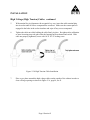
Adjust transformer to match the input line voltage as closely as possible. On non-SE
models, the correct line location will yield 235 to 245 VAC measured between the 0
terminal and the 240V terminal.
For non-SE models, it is necessary to insure that the line resistance meets requirements as
stated in Section B, General Information, Figure 2-0 page 6. To measure line resistance,
follow the next five steps.
1.
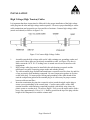
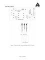
Connect an Ohm/Stat to the incoming line and an AC voltmeter to terminals
marked meter.
2.
Measure the input voltage and record the Eo number (no load voltage).
3.
Press the switch and record the Eb number (load voltage).
4.
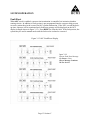
Calculate the Line Resistance using the following formula:
RL =Rd (Eo-Eb)
Example 2.75 (220-218) = 5.5 = 0.025
Eb
218
218
5.
RL = Line resistance
Eo = No Load Voltage
Eb = Load Voltage
Rd = Load Resistance (See Ohm/Stat for Rd value)
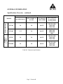
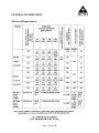
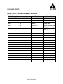
Refer to Table 2-0 for the maximum acceptable line resistance; if line resistance
exceeds the specification, contact factory.
Calibrating the System
After installation, the system must undergo a series of electrical checks. These are required to
validate system compliance. Refer to Section F, Calibration, and proceed to calibrate the HF
generator.
Verifying Programmed Techniques
After the calibration procedures have been completed, check the factory programmed techniques
for individual preference. Reference Section G, Programming/Utilities for procedures to edit
existing techniques or write new ones if and as needed.
Page 14 Section E