1
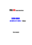
1/8 scale “Aeronca Champ” ARF Wingspan: Length: Wing Area: Weight (w/o battery): Weight (w/ PQ1800-3S): 52 in. (1320mm) 32 in. (813mm) 362 in². (23.35dm²) 28.8 oz. (816g) 33.8 oz. (958g) Pg.1 – Instructions Version 1.1, January 2009 © 2009-2010 Hobby Lobby International, Inc. All rights Reserved. • 5614 Franklin Pike Circle Brentwood, TN 37027 USA www.hobby-lobby.com Pg.2 – Instructions Version 1.1, January 2009 Introduction & History The full-scale Aeronca Champion, or “Champ,” was manufactured by the Aeronca Aircraft Corporation, in Middletown, Ohio between 1944 and 1951. Over 10,000 were built. In 1946, it was marketed as “the newest in aerodynamic design! . . . It’s the easiest plane you’ve ever flown. ” Like the Piper Cub with which it competed, the Champ also featured tandem seating. While the Piper Cub is soloed from the rear seat, the Champ can be soloed from the front seat, giving improved forward visibility on the ground, and during takeoffs, climbs, landings. Although the Aeronca Champ has a wider cabin than the Piper Cub, the Champ’s cruise speed was about 15mph faster. Its Continental 65hp engine powered it to a top speed of 100 mph. Pilot-1 is pleased to announce the 1/8 scale Aeronca Champ as part of the Golden Age Civilian Series. The Pilot-1 “Champ” encompasses the same attributes in quality construction and handling that made the original Aeronca Champ a favorite for over 50 years. Our engineers have spent countless hours developing a true-to-scale ARF that looks and flies like the full-scale Champ. We know you will be pleased with its scale looks and balanced maneuverability. In fact, our local model airplane pilots formed a line so they each could get a chance to fly the prototype. All agree, for scale aircraft, it may very well be the “easiest plane you’ve ever flown!” Hobby Lobby International, Inc. 5614 Franklin Pike Circle Brentwood, TN 37027 1-866-WE-FLY-RC (1-866-933-5972) www.hobby-lobby.com Pg.3 – Instructions Version 1.1, January 2009 Before starting, use the Contents list to take an inventory and make sure it is complete. If any parts are missing or are not of acceptable quality, contact Hobby-Lobby.com Support at 1-866-WE-FLY-RC (1-866-933-5972) Contents List Fuselage Battery Hatch Landing Gear Hatch Engine Cowl Landing Gear Wheels, Velcro, Misc Hardware Wings Wing Center Section Tube Wing Joiner Wing Struts Horizontal Tail Vertical Tail Pushrods Additional Items Required 4-channel Aircraft Radio w/ Receiver (minimum) 1800 mah, 3-cell, 11.1v Lipo battery (1800-2200mah) (4) Hitec HS-55 servos 18 amp Jeti Advance Plus Brushless ESC AXI 2217/16 Brushless Motor AXI 22 Series Radial Mount APC 9x6 “E” Propeller 5-minute Epoxy Glue Thin CA Glue Small Phillips screwdriver Needle Nose Pliers Hobby Knife Pg.4 – Instructions Version 1.1, January 2009 1. Prepare aileron servo mounting plate for installation. (Note: plywood tab with pullstring needs to be broken free with needle nose pliers.) 2. Turn on radio. Make sure the aileron trim is centered and all programming is reset to neutral. Install servo arm 90º to the plate and located in the center of slot. Drill the outer servo arm hole out to 3/64” (1.2mm) diameter. This hole is located 1/2” (13mm) from the center of the servo screw. 3. Attach 12” servo wire extension and secure with tape or heat shrink tubing. 4. Keep servo aligned per step 2. Mount servo as shown in photo using supplied hardwood blocks and screws. Use 5-min Epoxy to attach blocks. Pg.5 – Instructions Version 1.1, January 2009 5. Use tape to secure pull-string to servo wire. 6. Use needle nose pliers to break plywood tab. Carefully pull servo wire though wing section. 7. Install servo mounting plate with small sheet metal screws. 8. Remove aileron and fold CA hinges in half, as shown. Trial fit aileron in place before gluing. Careful attention should be placed on gaps at ends of aileron and tight spacing at the hinge line. Pg.6 – Instructions Version 1.1, January 2009 9. With the aileron tight and deflected downward, use 2 drops per hinge of thin CA to assure strong bonds. Use paper towel to remove any excess CA before drying. 10. Deflect aileron upwards and repeat application for bottom of wing. Note very small gap between aileron and wing. 11. Using a 90º triangle, mark aileron for location of control horn as shown in photo. 12. Use tape to hold aileron in neutral position. Install control horn so that holes in control horn are in line with the aileron hinge line. Remove covering under control horn with hobby knife. Trial fit horns, then use medium CA or 5-min Epoxy to glue horns in place. Pg.7 – Instructions Version 1.1, January 2009 13. Install pushrod and adjust clevis as necessary. Note the heat shrink tubing used here to prevent clevis from opening accidentally. 14. Install wing joiner into center section. Feed servo wire through holes and secure wing panel with machine screw and washer. 15. Repeat for opposite wing panel. 16. Install Rudder CA hinges using the same technique as the ailerons. Two drops of thin CA per hinge, on each side. Pg.8 – Instructions Version 1.1, January 2009 17. Install tailwheel bracket as shown in photo. 18. Install the Elevator CA hinges. Again, test fit for alignment and slight gap between the two surfaces. Note: you may wish to flex hinges back and forth several times before installation. 19. Temporarily install the wing with long machine screws and washers. 20. Test fit the tail assembly. Note the elevator is parallel to the wing and the rudder is perpendicular to the elevator. Assemble the tail section using 5-min epoxy. Be careful to maintain alignment during gluing. Pg.9 – Instructions Version 1.1, January 2009 21. Install screws into tailwheel bracket. 22. Turn on radio. Make sure the Elevator and Rudder trims are centered and all programming is reset to neutral. Drill the outer servo arm hole out to 3/64” (1.2mm) diameter. This hole is located 1/2” (13mm) from the center of the servo screw. Install on pushrod “z-bend” and slide each pushrod into guide tube. 23. Install servo arms at 90º to pushrod as shown in photo. Secure with servo arm screw. Mount your receiver with doublesided foam tape or Velcro. 24. Install control horns and clevis using the same technique as the ailerons. Note the elevator pushrod (short) is on the right side and the rudder pushrod (long) is on the left. We recommend using a clevis safety device fabricated from scrap fuel tubing, heat shrink tubing, or tape to prevent all plastic clevises from opening accidentally. Pg.10 – Instructions Version 1.1, January 2009 25. Install the landing gear using the nylon straps and sheet metal screws. 26. Install the wheels with a wheel collar on each side of each wheel. (Battery hatch shown installed with magnets in this photo.) 27. Solder connectors to motor, electronic speed control (ESC), and battery. Install motor on firewall per your motor’s instruction manual. Right and down thrust is already built into firewall, so you can mount motor flat against firewall. 28. Insert ESC into space above battery tray and route battery connector through lightening hole. Install Velcro to hold battery in place. You should run some CA around the edges of the Velcro to help stick to plywood. (Note: the airplane is upside down in this photo; you are looking toward the tail.) Pg.11 – Instructions Version 1.1, January 2009 29. Install servo wires into your receiver. Make sure all items are secure for flight. Install wing with machine screws and washers. 30. Install windshield with (4) sheet metal screws. 31. Install cowling with (4) sheet metal screws. Make sure the propeller has about 1/8” clearance from the front of the cowling. Install APC 9x6 “E-series” propeller. 32. Use a small foam block (approximately 7/8” tall) or towel to support center wing section with wingtips touching building table. Sight across the wings to check for twist and warp. You may also use an “incidence meter” to check for zero twist in Left and Right wing panels. If found, twist wing into desired position and remove new wrinkles in covering with iron or heat gun. Experienced builders may also add 1 degree of washout. Pg.12 – Instructions Version 1.1, January 2009 33. Install wing struts to fuselage using sheet metal screws. 34. Install landing gear / wing strut cover with sheet metal screw. 35. Make sure to support the wing center section with foam block (approx. 7/8” tall) or small towel. Be careful not to twist wing or apply too much pressure. Carefully install a screw into each wing strut as shown in photo. Note: The wing dihedral is 2 degrees. With plane upright and level, the height difference between the root rib (next to the fuselage) and the last full rib (the outer end of the aileron) is about 3/4" for each wing panel. 36. Locate the cable and crimp tubes for the tail flying wires. Pg.13 – Instructions Version 1.1, January 2009 37. Insert the cable through the crimp tube, then the fuselage bracket, and finally back through the crimp tube. Carefully pull tight and crimp the tube using needle nose pliers. Trim off excess wire. 38. Route cable thru tail as shown, making a diamond shape. 39. Insert cable through second crimp tube, fuselage bracket, and back through crimp tube. Carefully pull snug and crimp with needle nose pliers. Trim off excess as shown. Do not over-tighten. Tail brace wires are for scale appearance only. 40. Mark the CG on each wing at 1-3/4” (45mm) back from the leading edge. Install battery and balance model at these marks with the tips of your fingers. Move the battery fore or aft until airplane balances with fuselage level or slightly nose down. Make a mark in battery compartment so that you place the battery in the same place every time. Small stick-on lead weights may also be necessary inside engine cowl or near tail to properly balance. Pg.14 – Instructions Version 1.1, January 2009 41. Use your radio manual to set up Elevator travel and exponential as shown. Adjust Elevator to get 7/8” (21mm) UP and 5/8” (16mm) DOWN travel. Use 25% expo to soften the center travel per your radio manual. (JR/Spektrum +25% and Futaba/Hitec -25%) *This photo shows the measurement from the elevator neutral position to the full up position. Repeat for full down elevator. 42. Adjust Rudder travel to get 5/16” (10mm) LEFT and 5/16" (10mm) RIGHT. Use 20% expo to soften the center travel per your radio manual. (JR/Spektrum +20% and Futaba/Hitec -20%) *This photo shows the measurement from neutral to full right rudder. Repeat for full left rudder. 43. It is recommended to use two channels for the ailerons, one for the left aileron and one for the right aileron. Use your radio manual to help you do this. Adjust each aileron’s UP travel to get 1/2” (13mm) using end point adjustment. 44. Adjust each aileron’s DOWN travel to get 1/8” (4mm) using the end point adjustment. If your radio has a differential function, you may use that instead. Use 20% expo to soften the center travel per your radio manual. (JR/Spektrum +20% and Futaba/Hitec -20%) Pg.15 – Instructions Version 1.1, January 2009 45. Aileron-Rudder Mix: Setup your computer radio with an Aileron-to-Rudder mix of approx. 25%. This means when you move the Aileron stick to the LEFT (left aileron moves up), the Rudder will also move to the LEFT about 1/4" (6mm). Then move the aileron stick to the full right position (right aileron up) and the Rudder should also move to the right about 1/4” (6mm). We leave ours “ON” all the time. 46. Alternate Aileron Differential Method: If you are using a radio that does not have the capability to use a separate channel for each aileron as set up above, offset each control horn toward the front of the wing. This photo shows the left aileron servo as viewed from the left wingtip. The servo and aileron are both in the center (neutral) position. This allows the aileron to travel up more and travel down less (aileron differential). Pg.16 – Instructions Version 1.1, January 2009 Preflight If you are new to flying R/C aircraft, or a seasoned modeler, we recommend you have a fellow R/C modeler help you with the first flight. Some items you will need to complete on your first preflight are: 1. Aircraft assembled correctly and ready for flight. 2. All control throws and expos are set per this manual. 3. Transmitter fully charged and on correct model. 4. Aircraft balances at the recommended location. (1-3/4” aft of wing Leading Edge) 5. Flight Battery is fully charged and secure. 6. All electronics are operating correctly, proper direction, and secure. 7. Complete a radio Range Check per your radio manual. 8. Balance propeller and make sure it is secure. 9. Wait for a calm or light wind day for first flights. 10. If you are new to R/C flying, consider having an accomplished flyer make the first flight and trim the aircraft. A buddy-box training system is also very helpful. Flying You will soon find out the Pilot-1 Champ is a real pleasure to fly. Takeoffs, landings, and scale aerobatics are easy and well behaved. Even if you have never flown a tailwheel airplane before, the Pilot-1 Champ should be an easy transition. Landings are best accomplished by “three-pointing.” This means that all three wheels should touch at the same time and a little up-elevator is held until the aircraft comes to a complete stop. Except for takeoff and climb, you will only use about 1/2 throttle to maintain a scale flying speed. You can expect flight times of 12+ minutes depending on battery used and throttle management. We hope you enjoy your Pilot-1 Champ as much as we do! Happy Landings! WARNING – THIS IS NOT A TOY! Radio controlled model aircraft are capable of inflicting serious injury and/or property damage if not assembled, operated, and maintained in a competent and safe manner. If you are not already experienced with radio controlled models, we strongly suggest that you find an experienced modeler to assist you. Warranty Hobby-Lobby guarantees this kit to be free from defects in both material and workmanship at the date of purchase. This warrant y does not cover any component parts damaged by use or modification. In no event shall Hobby-Lobby’s liability exceed the original cost of the purchased kit. Completely read through this manual before starting construction. Pg.17 – Instructions Version 1.1, January 2009 2008 Official Academy of Model Aeronautics National Model Aircraft Safety Code GENERAL 1. A model aircraft shall be defined as a non-human-carrying device capable of sustained flight in the atmosphere. It shall not exceed limitations established in this code and is intended to be used exclusively for recreational or competition activity. 2. The maximum takeoff weight of a model aircraft, including fuel, is 55 pounds, except for those flown under the AMA Experimental Aircraft Rules. 3. I will abide by this Safety Code and all rules established for the flying site I use. I will not willfully fly my model aircraft in a reckless and/or dangerous manner. 4. I will not fly my model aircraft in sanctioned events, air shows, or model demonstrations until it has been proven airworthy. 5. I will not fly my model aircraft higher than approximately 400 feet above ground level, when within three (3) miles of an airport without notifying the airport operator. I will yield the right-of-way and avoid flying in the proximity of full-scale aircraft, utilizing a spotter when appropriate. 6. I will not fly my model aircraft unless it is identified with my name and address, or AMA number, inside or affixed to the outside of the model aircraft. This does not apply to model aircraft flown indoors. 7. I will not operate model aircraft with metal-blade propellers or with gaseous boosts (other than air), nor will I operate model aircraft with fuels containing tetranitromethane or hydrazine. 8. I will not operate model aircraft carrying pyrotechnic devices which explode burn, or propel a projectile of any kind. Exceptions include Free Flight fuses or devices that burn producing smoke and are securely attached to the model aircraft during flight. Rocket motors up to a G-series size may be used, provided they remain firmly attached to the model aircraft during flight. Model rockets may be flown in accordance with the National Model Rocketry Safety Code; however, they may not be launched from model aircraft. Officially designated AMA Air Show Teams (AST) are authorized to use devices and practices as defined within the Air Show Advisory Committee Document. 9. I will not operate my model aircraft while under the influence of alcohol or within eight (8) hours of having consumed alcohol. 10. I will not operate my model aircraft while using any drug which could adversely affect my ability to safely control my model aircraft. 11. Children under six (6) years old are only allowed on a flightline or in a flight area as a pilot or while under flight instruction. 12. When and where required by rule, helmets must be properly worn and fastened. They must be OSHA, DOT, ANSI, SNELL or NOCSAE approved or comply with comparable standards. RADIO CONTROL 1. All model flying shall be conducted in a manner to avoid over flight of unprotected people. 2. I will have completed a successful radio equipment ground-range check before the first flight of a new or repaired model aircraft. 3. I will not fly my model aircraft in the presence of spectators until I become a proficient flier, unless I am assisted by an experienced pilot. 4. At all flying sites a line must be established, in front of which all flying takes place. Only personnel associated with flying the model aircraft are allowed at or in front of the line. In the case of airshows demonstrations straight line must be established. An area away from the line must be maintained for spectators. Intentional flying behind the line is prohibited. 5. I will operate my model aircraft using only radio-control frequencies currently allowed by the Federal Communications Commission (FCC). Only individuals properly licensed by the FCC are authorized to operate equipment on Amateur Band frequencies. 6. I will not knowingly operate my model aircraft within three (3) miles of any preexisting flying site without a frequency-management agreement. A frequency management agreement may be an (continued) Pg.18 – Instructions Version 1.1, January 2009 7. 8. 9. 10. allocation of frequencies for each site, a day-use agreement between sites, or testing which determines that no interference exists. A frequency-management agreement may exist between two or more AMA chartered clubs, AMA clubs and individual AMA members, or individual AMA members. Frequency-management agreements, including an interference test report if the agreement indicates no interference exists, will be signed by all parties and copies provided to AMA Headquarters. With the exception of events flown under official AMA rules, no powered model may be flown outdoors closer than 25 feet to any individual, except for the pilot and located at the flightline. Under no circumstances may a pilot or other person touch a model aircraft in flight while it is still under power, except to divert it from striking an individual. Radio-controlled night flying is limited to low-performance model aircraft (less than 100 mph). The model aircraft must be equipped with a lighting system which clearly defines the aircraft's attitude and direction at all times. The operator of a radio-controlled model aircraft shall control it during the entire flight, maintaining visual contact without enhancement other than by corrective lenses that are prescribed for the pilot. No model aircraft shall be equipped with devices which allow it to be flown to a selected location which is beyond the visual range of the pilot. PARK FLYER SAFE OPERATING RECOMMENDATIONS Inspect your model before every flight to make certain it is airworthy. Be aware of any other radio frequency user who may present an interference problem. Always be courteous and respectful of other users of your selected flight area. Choose an area clear of obstacles and large enough to safely accommodate your flying activity. Make certain this area is clear of friends and spectators prior to launching your aircraft. Be aware of other activities in the vicinity of your flight path that could cause potential conflict. Carefully plan your flight path prior to launch. Abide by any and all established AMA National Model Aircraft Safety Code. Pg.19 – Instructions Version 1.1, January 2009 Hobby Lobby International, Inc. 5614 Franklin Pike Circle Brentwood, TN 37027 1-866-WE-FLY-RC (1-866-933-5972) www.hobby-lobby.com © 2009-2010 Hobby Lobby International, Inc. All rights Reserved. • 5614 Franklin Pike Circle Brentwood, TN 37027 USA www.hobby-lobby.com Pg.20 – Instructions Version 1.1, January 2009