1
C.U. Swing Door Operator Installation Manual
All installation changes and adjustments must be made by qualified, NABCO trained
technicians. The purpose of this manual is to familiarize the purchaser with the proper
installation and operation of a NABCO surface applied swinger system. It is essential
that this equipment be properly installed and operational before the door is used by
the public. The installed system must comply with all applicable standards. In the United States, ANSI Standard
156.10 for GT 400 or 8400 (refer to chart below) or ANSI 156.19 for GT 500 or 8500 covers these types of doors.
Other local standards or codes may apply. Use them in addition to the ANSI standard. The GT 400 or GT8400 and
GT 500 or GT8500 Model Units are listed with Underwriters Laboratory and are identified as such on the label.
TO THE
INSTALLER
Instruct the building owners and operator on the essentials of the operation of the door and this device. The owner
should follow these instructions to determine whether the door is operating properly and should immediately call for
service if there is any malfunction.
OVERVIEW
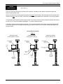
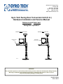
Gyro Tech Swing Door Conversion Unit (C.U.) operators are designed to be installed
to the surface of the door frame. The operator is controlled by either the Gyro Tech
Magnum or U series microprocessor based controllers or Model 1400 analog control.
These controllers offers many features to accommodate most installation options. This manual provides step by step
instructions to install the C.U. header and arm assemblies. Refer to your accompanying controller manual for information on wiring and adjusting the controller. Included in the controller manual you will find a trouble-shooting section
and optional wiring diagrams.
SPECIFICATIONS
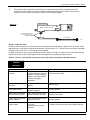
Models:
Conversion Unit Models
Base Model
Conversion Unit
(CU)
Bottom Load
Conversion Unit
(CU)
Side Load
Model
Model
Full Automatic (mechanical closer)
GT 400
GT 8400
Low Energy (mechanical closer)
GT 500
GT 8500
Available controls:............................................................. Model GT-400 or GT-8400 is available with:
Magnum, U Series or Analog Control
Model GT-500 or GT-8500 is available with:
Magnum or Analog Control Only
Minimum Frame Face for Mounting.................................. 1 ¾” (44 mm)
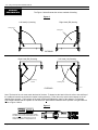
Minimum Clearance from Top of ..................................... Bottom Load: 6 1/8” (156 mm)
Door to Ceiling
Side Load: 7 1/8” (181 mm)
Door Hinge Requirements ............................................... Butt, Offset Pivot, Center Pivot or Swing Clear Hinges
Door Thickness ................................................................ 1 ¾” (44 mm) Minimum
Door Width ....................................................................... Specify When Ordering
• Use of a supplemental door stop is always required.
Page 4
www.NabcoEntrances.com
7-26-07