1
C.U. Swing Door Operator Installation Manual
INSTALLATION:
Steps 1 to 9
Bottom Load
Steps 10-15
Side Load Unit
Steps 16-22
Both
BOTTOM LOAD
ONLY
Step 1 - Remove material from packages and check contents:
Remove all contents from the carton. Check all items to ensure you have the material you need before beginning the
actual installation.
Step 2 - Remove access panel from header housing assembly:
Carefully remove the header housing assembly from the cardboard carton. Using a Phillips screwdriver, remove the
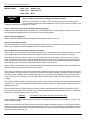
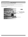
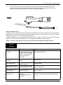
Access Panel (see Fig 1 on page 5). Use a pencil to mark the locations of the Access Panel Mounting Brackets. This
will make it easy to place the brackets back in the correct position when re-installing the Access Panel. Refer to Figure 5 below.
Mark the location of the Access Panel Mounting Brackets with a pencil
Note that when reinstalling the brackets, that the tabs on the brackets
should be facing downward.
Figure 5
Step 3 - Remove paperwork:
DN 0078
Remove all decals, paperwork and parts bag from inside header and set to one side.
Step 4 - Install wiring in frame:
All conduit and switch or sensor wires must be pulled through the frame or wall before mounting the operator housing.
Refer to your separate Controller Installation Manual for wiring instructions.
Step 5 - Mount header housing assembly on door frame:
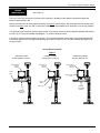
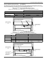
Refer to figures on next page. The following instructions refer to mounting the unit on aluminum framing. If the unit is
not being installed on an aluminum frame then adequate structural framing must be available for mounting.
Note: There is a difference in the location of the operator spindle between inswing and outswing header housing assemblies. Therefore the width of the base pivot plate on which the operator is mounted is varied according to the type
of door; inswing, outswing, with or without finger guard, etc. Refer to Figure 7 Page 9. To ensure you are matching
the correct header housing to the door you are working on, refer to the table on the above mentioned page.
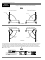
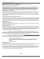
Once all wiring is in place, using the empty header mounting brackets as a template, hold the header against the
frame, and mark the mounting holes on the jamb tubes as shown on the following page. Ensure bottom of header
housing assembly is 1-1/8” up from the top of the door as shown in Figure 6 on Page 9. The center line of the three
holes on the end mounting brackets must be located one (1) inch away from the edge of the door frame as shown.
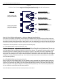
NABCO recommends the use of Rivnuts when mounting the header to aluminum framing. Using a #Q sized drill bit
(0.332 DIA), drill out the four holes per bracket in the jamb tubes and countersink the holes 0.531 DIA x 100o and insert the supplied Rivnuts. Using a Rivnut setting tool, expand the Rivnuts in the aluminum frame until they are “snug”.
Caution!
Over tightening the Rivnuts will cause the threads to strip.
Once all holes are properly drilled and Rivnuts installed, mount header housing to frame using the six 1/4-20 x 1” flat
header screws provided. Affix the tape onto the end caps and mounting brackets to cover the mounting screws and
end cap screws.
NABCO recommends the use of Rivnuts when mounting the header to aluminum framing. On other types of installations such as hollow metal door frames, adequate backing such as 2” x 10” wood backing is required above the top of
the frame for anchoring the header housing to the wall. Using this method would require lag bolts instead of 1/4 x 20
Rivnuts to properly anchor the unit.
Page 8
www.NabcoEntrances.com
7-26-07