1
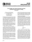
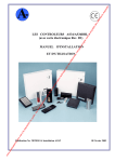
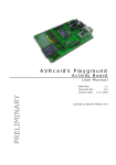
ICC 50
ICC 80
ICC BIPOLAR
08.99
Service manual
ERBE
ICC 50, ICC 80, ICC BIPOLAR
Service manual
10122-003, 10122-008, 10122-010, 10122-040, 10122-041
10122-100, 10122-101, 10122-102, 10122-103, 10122-104
10122-054, 10122-055, 10122-060, 10122-061
08.99
This manual was created by
Michael Grosse
Dipl.-Phys. (Physics)
Tel.:
+49(0)70 71 / 755-254
Fax.:
+49(0)70 71 / 755-5254
E-Mail: [email protected]
http://www.erbe-med.de
Please contact me directly with your
suggestions, criticisms or information
regarding this manual. Your feedback
helps me to design this document
according to your requirements and to
constantly improve it.
All rights to this service manual, particularly the right to reproduction, distribution and translation, are
reserved. No part of this service manual may be reproduced in any form (including photocopying, microfilm
or other means), or processed, reproduced or distributed by means of electronic systems without prior
written permission from ERBE Elektromedizin GmbH.
The information contained in this service manual may be revised or extended without prior notice and
represents no obligation on the part of ERBE Elektromedizin GmbH.
Copyright © ERBE Elektromedizin GmbH, Tübingen1999
Printed by: ERBE Elektromedizin GmbH, Tübingen
Printed in Germany
4 / 58
Art. No.: 80116-251
Contents
Chapter
Title
Page
Table of contents ................................................................................................. 5
1
Test programs ...................................................................................................... 7
2
ERROR list ........................................................................................................ 17
3
Adjustment and testing instructions .................................................................. 25
4
Circuit diagrams ................................................................................................ 33
5
Appendix and addresses .................................................................................... 53
Art. No. 80116-251
08 / 99
0
5 / 58
CHAPTER 1
Test programs
Test programs
ICC 50, ICC 80, ICC BIPOLAR
No. Test program function
1 Basic setting of the front panel
2 Calling up the Error list
3 Programming the required activation time limitation
4 Activation of all visual front panel displays
5 Activation of the audible signals
6 Manual closure of the output relays
7 (not assigned)
8 Display of the software version number
9 (not assigned)
10 Measurement of the internal 15 volt supply voltage
11 Automatic verification of the power supply unit for the entire range of 0…90 volts
12 Adjustment of the phase control for the HF generator
13 Calibration of the HF power output
14 Automatic calibration of the NE monitor
15 Verification of the activation signals (accessories) and safety shut off feature
16 Automatic burn-in procedure for two hours
17 Setup of programmable options
18 (not assigned)
19 (not assigned)
20 Selection of content for the CONFIG register of the microcontroller
Art. No. 80116-251
08 / 99
21 Verification of the modulation timer and the modulation monitor
1 Test programs
9 / 58
Test programs
ICC 50, ICC 80, ICC BIPOLAR
Calling up the test programs
When switching on the unit, hold down the CUT effect key. »Pr. 1« appears in the displays on the front
panel.
The required test program number can be selected via the »Up/Down« keys in the COAG field.
The selected test program is started by pressing the CUT effect key.
If not described differently, the individual test programs can be cancelled and exited again by briefly pressing
the CUT effect key.
1
Basic setting of the front panel
Set the front panel as required. (Attention: to switch over the CUT effect, only press the effect key briefly,
since the Save process is started if it is pressed for a longer period of time!)
To save, the CUT effect key must be held down for about 3 seconds. At the same time, the Save process is
indicated symbolically in the display together with an acoustic signal. Once the Save has been completed,
there is a short tone. If the CUT effect key is released too soon, nothing is saved and therefore the previous
setting or the setting preprogrammed at the factory for the front panel is again valid.
Once the Save has been completed, Test program 1 is exited by releasing the CUT effect key.
If Test program 1 is exited without storing a new front panel setting, the unit must be switched off to do this.
2
Calling up the ERROR list
The ICC units are equipped with a system for error detection, error indication and error memory. Every
error is labelled with an error number (ERROR No.). The ICC 50, ICC 80 and ICC BIPOLAR units store
the last 20 ERROR numbers. Test program 2 indicates the stored ERROR numbers. The most recent error
is in Memory location 1.
After activating Test program 2, the display »Er-.—« appears for about 1 second, and then 1. xx, where
»1.« stands for the last error and »xx« is the number of the error described in the error list.
Using the Up/Down keys in the CUT field, the 20 stored errors can be selected. For example, »2.« then
stands for the penultimate error, »3.« stands for one before that, etc.
Press the CUT effect key for 3 seconds to delete the entire error memory. This is indicated acoustically and
symbolically in the displays. The deletion is complete when a short tone is heard. If the CUT effect key is
released too soon, the memory is not deleted.
Then exit the test program.
To exit the test program without deleting the memory only briefly press the CUT effect key.
3
Programming the required activation time limit
Display of »tL.« for time limit and »—«for the required limit value.
Using the Up/ Down keys in the COAG field, the permissible activation time is set in seconds.
10 / 58
1 Test programs
Test programs
ICC 50, ICC 80, ICC BIPOLAR
Range: 1…99 seconds.
This value must be stored in memory by pressing the CUT effect key for about 3 seconds. Refer to Test
program 1.
It is possible to exit the test program without saving a new value to memory by briefly pressing the CUT
effect key.
4
Activation of all visual front panel displays
5
Activation of all acoustic signals
Audible signals are selected using the »Up/Down« buttons in the CUT field (display t.x). By pressing any
button in the COAG field, the alarm volume can be adjusted.
•
t.1: Signal for activation CUT
•
t.2: Signal for activation FORCED and SOFT
•
t.3: Signal for activation BIPOLAR
•
t.4: Alarm signal
6
Manual closing of the output relay
Display: r.x xx, in which »r.x« stands for the relay number.
Art. No. 80116-251
08 / 99
By pressing any button in the COAG field, the two relays can be switched as required, which is indicated by
»on« in the COAG display.
•
r.1: Bipolar output
•
r.2: Monopolar output with neutral electrode output
•
r.r.: Both outputs
7
(not assigned)
8
Display of software version number (Display: S.n. xx)
9
(not assigned)
10
Measurement of the internal 15 volt supply voltage (»U dd« for Vdd)
11
Automatic checking of the power supply unit for the entire range 0…90 V
Automatic testing is activated with the footswitch for CUT. During the run of the test, indicated symbolically
in the COAG display, the footswitch must remain pressed.
The voltage is increased from 0 to 90 volts and measured internally at the same time. If there is a difference,
this may be displayed as an error (ERROR 80 and 81).
After this run, a voltage of 90 volts is set which can be measured between MP2 and MP1. The measurement
value of the internal measurement is indicated in the COAG display.
1 Test programs
11 / 58
Test programs
ICC 50, ICC 80, ICC BIPOLAR
By pressing the CUT effect button, the voltage is decreased to 50 volts.
By pressing the CUT effect key again, the test program is exited.
Test program 12
12
Adjustment of the phase control for the HF generator
This adjustment is made as the generator idles, but with the monopolar patient lines connected.
After starting up the test program, the power unit voltage is set to 10 volts (Display: U_ 10).
Using the CUT footswitch, the generator is activated. The HF voltage is measured using an oscilloscope
and adjusted to a sinusoidal characteristic at TP3. During activation, the power unit current (I_ xx) is
displayed, which must at the same time be at its minimum.
As soon as the footswitch is released, the power unit voltage is automatically set to 50 volts. The generator
is again activated using the CUT footswitch and set at this higher voltage as described above.
Then the whole process is repeated for a power unit voltage of 90 volts. For the final adjustment, the clean
sinusoidal characteristic has a higher priority than the power unit current, which should nevertheless be
close to its minimum.
By then releasing the CUT footswitch, the test program is automatically exited.
13
Calibration of the HF power output (c.P. hF)
ATTENTION
This test program can only be conducted in the unit's Special Test Mode. To do this, the bridge J7 must be
connected, otherwise the display »J7 n.c.« will appear.
An HF power meter (APM 600) is connected to the monopolar output. CUT is activated with the footswitch
at a load resistance of 500 ohms set at the output. Via the »Up/Down« keys in the CUT field, the output
power is adjusted in such a way that the value measured by the power meter corresponds to the setup value
on the front panel.
Proceed in the same manner at a load resistance of 200 ohms when activating SOFT. Here the power is set
via the »Up/Down« keys in the COAG field to the preset value.
To save the calibration values, the CUT effect key must be held down for approx. 3 seconds until a high
tone is heard which indicates that these have been saved to memory.
14
Automatic calibration of the NE monitoring
ATTENTION
This program can only be conducted in the unit's Special Test Mode. To do this, the bridge J7 must be
connected. Otherwise the display »J7 n.c.« will appear.
12 / 58
1 Test programs
Test programs
ICC 50, ICC 80, ICC BIPOLAR
At the NE socket a resistance of 260 ohms is connected via a standard NE cable. Then the reference value
for the NE monitoring is automatically adjusted by the unit, which is indicated by the appearance of an
unbroken line (»—«) in the COAG display and the illumination of both the red and the green NE LEDs.
This calibration value must now be stored by holding down the CUT effect key for 3 seconds.
15
Checking the activation signals (accessories) and safety shut off feature
All four activation signals (finger- and footswitch) must be pressed at least once so that instead of »— —«
a display of »oo oo« appears and the test program is automatically finished.
16
Automatic burn-in procedure for 2 hours (»2h b.i.«)
Automatic burn-in procedure for 2 hours (»2h b.i.«) with 25% activation (10 sec ON, 30 sec OFF), in which
the maximum power (50 watts) is output for CUT at 500 ohms.
A 500 ohm load resistance (noninductive and noncapacitive) is connected to the monopolar output.
Before the burn-in procedure can be started, the CUT footswitch signal must be present.
Start the procedure with the CUT effect key.
17
Setting programmable options (»P.O.«)
For example, to lock the activation signals according to Spanish regulations.
ATTENTION
This program can only be conducted in the unit's Special Test Mode. To do this, the bridge J7 must be
connected. Otherwise the display »J7 n.c.« will appear.
The possible options can be called up in the COAG field via the »Up/Down« keys. To save the option
currently displayed, or to switch the unit to this mode, the CUT effect key must be held down for approx. 3
seconds as for all save procedures.
Art. No. 80116-251
08 / 99
Options:
•
St.: Standard
•
SP.: Spanish version: if another activation signal is detected during activation, the unit switches off
immediately with an error message.
18
(not assigned)
19
(not assigned)
20
Display contents of the CONFIG register
Display the contents of the CONFIG register to determine the basic initialization of the microcontroller
(»c.r. xx«).
1 Test programs
13 / 58
Test programs
ICC 50, ICC 80, ICC BIPOLAR
21
Verification of the modulation timer and the modulation monitor (»t.t.«)
At the test program start, the timer is initialized and switched on. Activation using the CUT footswitch turns
on the generator (with the output relay open) and the feedback is measured. In the COAG display, the
measurement value for the feedback is indicated. This must accept a value of 30 (28–32). Greater deviations
are not permitted.
14 / 58
1 Test programs
1 Test programs
15 / 58
Art. No. 80116-251
08 / 99
CHAPTER 2
ERROR list
ERROR list V 3.X
ERBOTOM ICC 50, ICC 80, ICC BIPOLAR
Automatic error detection, indication and documentation
ERBOTOM ICC series high-frequency surgical units are equipped with a device for automatic error detection,
indication and documentation (ERROR monitor).
Error detection
For ERBOTOM ICC series equipment with software version 1.07, the ERROR monitor can detect up to 91
different errors, depending on the type of equipment and its features, and indicate these on the display.
Error indication
Error numbers (ERROR nos.) are assigned to the various errors. If an error is detected, it is immediately
reported. The error report is both and visual and audible.
Error documentation
The error numbers of detected errors are automatically saved in chronological order. Since only 20 memory
locations are available, only the last 20 error messages are displayed. If the same error is detected several
times in a row, the corresponding error number is then saved only once in consideration of the limited number
of available memory locations. The error numbers documented in memory can be displayed via Test program
2 and deleted.
Troubleshooting for ICC family equipment
The ICC equipment family is equipped with an error detection system which records the last 20 (ICC 50, ICC
80, ICC BIPOLAR) errors in an ERROR list and saves them in memory. This error memory can be called up
via Test program no. 2. The idea of troubleshooting is to help the user of the equipment in the event of
malfunction. He should thus be capable of localizing errors himself and deciding whether this is an operational
error or an error originating with the accessories which he can possibly remedy himself, or whether it is
necessary to contact the technical service.
Art. No. 80116-251
08 / 99
If there is a complete failure of the system and no display is visible, the power supply may have been interrupted
or the voltage supply inside the unit is defective. In such a case, first check whether the outlet used is live or a
fuse in the house power supply has been tripped (Does a different unit function at this outlet?). If the outlet
used is live, check the powerline to the unit and replace if necessary. The equipment fuses on the rear panel
should also be checked and replaced if necessary.
If these efforts produce no results, there is presumably an error within the unit. You should then contact the
technical service.
In the case of a malfunction with a properly functioning display, but without indication of an ERROR number
on the display, the error may be located in defective accessories. There may, for example, be a defect in the
fingerswitch or footswitch, or there may be a power interruption. The cause of the error may be determined by
exchanging the accessories used.
To determine other causes of errors, an ERROR number in the unit display indicates the course of further
action according to the following table.
2 ERROR list
19 / 58
ERROR nos. 1–13
Error
no. Explanation and remedy
1
Activation time limit reached.
If the activation time limit has been set too short, extend this by using Test program no. 3.
During monopolar activation, the NE monitor produces an impermissible value.
2 Check whether the NE is correctly applied and connected to the unit. Check the NE lines.
Tech. Service: Check NE monitor.
Activation of the unit without prior acknowledgement of the front panel setting.
3 Setup values on the front panel must be acknowledged by pressing any key before the unit
can be reactivated.
4
Activation of CUT with nonspecified power setting.
With a nonspecified power setting, the CUT function is inactive.
5
Activation of COAG with nonspecified power setting.
With a nonspecified power setting, the COAG function is inactive.
Activation of COAG with fingerswitch at BIPOLAR setting.
6 The unit is setup for bipolar coagulation and cannot therefore be activated with the
fingerswitch for coagulation, but rather only with the footswitch or via AUTO START.
Several activation signals simultaneously.
If several activation signals were not simultaneously activated, check the fingerswitch and
7 footswitch for correct functioning.
Check the activation detection of the unit with the help of Test program 15. If errors are
detected: Tech. Service
8
(Only for the version according to Spanish regulations: During activation, a further activation
signal leads to shutdown.)
9 (not assigned.)
10
Power supply unit voltage too high during self-check.
Equipment error: Tech. Service.
Incorrect dosage during activation phase: Power supply unit current too high before switching
11 on the generator.
Generator defective: Tech. Service
20 / 58
12
Incorrect dosage during activation phase: Power supply voltage too high.
Equipment error: Tech. Service
13
Incorrect dosage during activation phase: Power supply voltage too high.
Equipment error: Tech. Service
2 ERROR list
ERROR nos. 14–25
Error Explanation and remedy
No.
14
Incorrect dosage during CUT: Voltage 20% too high.
Equipment error: Tech. Service.
15
Incorrect dosage during FORCED: 20% too high.
Equipment error: Tech. Service.
16
Incorrect dosage during SOFT or BIPOLAR: Voltage 20% too high.
Equipment error: Tech. Service.
Incorrect dosage during CUT Effect 2 or FORCED: Modulation pulse length outside
17 permissible tolerance limits.
Equipment error: Tech. Service.
Incorrect dosage during CUT Effect 2 or FORCED: Modulation frequency outside permissible
18 tolerance limits.
Equipment error: Tech. Service.
19
Current measurement produces impermissibly low value during activation phase.
Equipment error: Tech. Service.
Activation signal present when switching on the unit
Release footswitch CUT key.
20
Check function of footswitch.
Check activation detection of the unit with the help of Test program 15.
Activation signal present when switching on the unit
Release footswitch COAG key.
21
Check function of footswitch.
Check activation detection of the unit with the help of Test program 15.
Art. No. 80116-251
08 / 99
Activation signal present when switching on the unit
Release fingerswitch CUT key.
22
Check function of fingerswitch.
Check activation detection of the unit with the help of Test program 15.
Activation signal present when switching on the unit
Release fingerswitch COAG key.
23
Check function of fingerswitch.
Check activation detection of the unit with the help of Test program 15.
»Up« key in CUT field of the unit pressed or defective.
24 Check whether the corresponding key was pressed before switching on the unit.
If not: Front panel or unit defective, Tech. Service.
»Down« key in CUT field of the unit pressed or defective.
25 Check whether the corresponding key was pressed before switching on the unit.
If not: Front panel or unit defective, Tech. Service.
2 ERROR list
21 / 58
ERROR nos. 26–64
Error
No. Explanation and remedy
»COAG« mode scroll key pressed when switching on the unit or defective.
26 Check whether the corresponding key was pressed before switching on the unit.
If not: Front panel or unit defective, Tech. Service.
»Up« key in COAG field pressed when switching on the unit or defective
27 Check whether the corresponding key was pressed before switching on the unit.
If not: Font panel or unit defective, Tech. Service.
»Down« key in COAG field pressed when switching on the unit or defective.
28 Check whether the corresponding key was pressed before switching on the unit.
If not: Front panel or unit defective, Tech. Service.
29 (not assigned.)
30
During the activation phase, no feedback is present at the safety shut off feature.
Equipment error: Tech. Service.
31–59 (not assigned.)
Error when switching on the unit: Memory value for calibration of power control invalid or power
control not yet calibrated.
Unit is available but the power output is limited to lower value, which is indicated with every
60
activation by a brief blinking of the incorrect dosage LED. Power must be calibrated with the
help of Test program 13.
Otherwise: Memory failure, Tech. Service.
Error when switching on the unit: Memory value for calibration of the NE monitor invalid or NE
monitor not yet calibrated.
61 Unit is available but only non-split neutral electrodes should be used. NE monitor must be
calibrated with the help of Test program 14.
Otherwise: Memory failure, Tech. Service.
Error in calibration (Test programs 13 and 14): Value to be stored in memory is impermissible.
Possibly no adjustment or an incorrect adjustment was made.
62 For NE adjustment (Test program 14), check whether the correct resistance is connected to
the NE line.
Otherwise: Equipment error, Tech. Service
Error when storing a value in memory (front panel basic setting or calibration value) in
63 EEPROM. Storage not successful.
Memory failure, Tech. Service.
Error when switching on the unit: The value stored in memory is invalid for the programmable
option.
64
Unit is available.
Otherwise: Memory failure, Tech. Service.
22 / 58
2 ERROR list
ERROR nos. 65–93
Error Explanation and remedy
No.
65–79 (not assigned.)
80
Error when checking the power supply unit (Test program 11): Voltage too low.
Equipment error: Tech. Service.
81
Error when checking the power supply unit (Test program 11): Voltage too high.
Equipment error: Tech. Service.
Error when checking the power supply unit (Test program 11): Power supply unit current too
82 high.
Equipment error: Tech. Service.
Burn-in procedure started without CUT footswitch.
83 Before activation of the burn-in procedure (Test program 16), the footswitch signal for CUT
must be present.
84–89 (not assigned.)
90
System error: Watch Dog has triggered Interrupt and Reset
Equipment error: Tech. Service.
91
System error: Clock monitor has triggered Interrupt and Reset
Equipment error: Tech. Service.
92
System error: Faulty opcode; Interrupt triggered.
Equipment error: Tech. Service.
Art. No. 80116-251
08 / 99
System error: Stack range exceeded.
93 This error is only stored in memory, i.e. no immediate display on the front panel.
Equipment error: Tech. Service.
2 ERROR list
23 / 58
CHAPTER 3
Adjustment and
testing
instructions
Adjustment and testing
instructions
ICC 50, ICC 80, ICC BIPOLAR
General remarks
All ERBE equipment is adjusted before shipping and subjected to a burn-in test and a final inspection.
Nevertheless, repairs, the replacement of boards, extremely abnormal operating conditions or
customization require readjustment of the equipment under certain circumstances.
The following instructions for adjustment of HF surgical units ICC 50, ICC 80 and ICC BIPOLAR allow
the service technician to perform all adjustment work. This adjustment work must only be performed by
the manufacturer or by third parties expressly authorized to do this by the manufacturer in consideration of
the particular safety requirements for electromedical equipment.
WARNING
A maladjustment can lead to patient injury as well as to damage to the equipment.
ATTENTION
If nonauthorized persons perform improper adjustments, modifications or repairs to the unit or accessories,
the manufacturer accepts no liability. In addition, the guarantee becomes void in this case.
No. Adjustment or testing of:
1 Basic initialization
2 Testing the internal power supply Vdd (+15 V)
3 Checking the power supply unit, voltage control and monitor
4 Setting the phase control of the HF generator
5 Calibration of the HF power output
Art. No. 80116-251
08 / 99
6 Calibration of the NE monitor
7 Checking the activation signals and safety interlock signal.
ATTENTION
If individual assemblies are replaced during repairs, either a partial readjustment or a complete reset must
be performed, depending on the assembly involved.
3
Adjustment and testing instructions
27 / 58
Adjustment and testing
instructions
ICC 50, ICC 80, ICC BIPOLAR
An essential component of the ICC 50, ICC 80 and ICC BIPOLAR unit is the microcontroller (68HC11A1),
which directly influences almost all functions of equipment and unifies a large number of functions through
its capabilities. These include, for example, the analog measurement inputs, self-monitoring functions, and
much more. Of particular importance is the internal EEPROM, which is used to store data, calibration
values etc. permanently and independent of the supply voltage.
On the other hand, this microcontroller requires basic initialization for its application in order to activate
required functions and adapt to its environment. This basic initialization must be conducted first for the
ICC 50, ICC 80 and ICC BIPOLAR, while at the same time the specific parameters are automatically
saved.
ATTENTION
The adjustment or testing of nos. 1–7 absolutely must be performed in the indicated order for new equipment
and also after replacement of the microcontroller!
Since most setup values are stored as calibration values in the EEPROM of the microcontroller, the test
programs in which these calibration values can be changed are only accessible in the so-called »Special
Test Mode«. This is used to prevent unintentional alteration of the calibration values. To operate the unit in
the Special Test Mode, a shorting bridge must be attached at J7 (main board). If the presence of this
shorting bridge is detected when the unit is switched on, this is made clear in that the unit is automatically
in the test program mode after switching on and Test program 10 (»Pr. 10«) is displayed. Furthermore,
when first switching on the unit in Special Test Mode, the basic initialization is automatically performed
and saved.
The shorting bridge absolutely must be removed once the setting has been completed, as otherwise several
internal safety monitors of the microcontroller are not activated, In addition, the unit would always be in
test program mode after switching on and not in the normal operating mode.
Fig.: Position of J7 on the main board
(refer to text above).
28 / 58
3
Adjustment and testing
Adjustment and testing
instructions
ICC 50, ICC 80, ICC BIPOLAR
1
Basic initialization
Attach the shorting bridge to J7.
Switch the unit on.
At the same time, basic initialization is automatically performed insofar as this has not already occurred
with the respective microcontroller.
The unit is in the test program mode after switching on. On the front panel appears »Pr. 10«.
2
Testing the internal supply voltage Vdd (+15V)
Activate Test program 10.
Display on the front panel: U dd for Vdd (for about 1 second)
Next follows the display of the voltage measured: xx. yy.
(xx = integer volt; yy = tenth and hundreth volt).
Voltage must be 15 V, tolerance: ±0.5 V.
Although only the voltage Vdd (+15 V) is directly measured, this test program also checks the 5 V voltage
used as a measurement reference. In the event of malfunction, this should therefore also be measured.
Deactivate the test program.
3
Checking the power supply unit, voltage control and monitoring
Both measurements should be checked using a meter at MP2 (main board; mass = MP1)!
Activate Test program 11.
Display on the front panel: U_ for »DC power supply unit«.
The check is started by activating with the CUT footswitch.
CAUTION
Art. No. 80116-251
08 / 99
During the automatic run, the footswitch must remain depressed, as otherwise the power supply unit is
switched on, which results in an error report (Error 80).
The power supply voltage is now slowly increased from 0 to 90 volts, measured simultaneously and monitored
for uniformity within a narrow tolerance. In the event of a malfunction, the error is displayed and the test
program interrupted. The voltage increase is indicated symbolically in the COAG display.
After a complete check of the entire voltage range, the voltage remains at 90 volts, and the internal
measurement value is indicated in whole volts in the COAG display. Here as well, the footswitch must
remain depressed.
The measurement value must be 90 V, tolerance: ±2 V.
By pressing the CUT effect key, the voltage is reduced to 50 V and displayed as described above.
The measurement value must be 50 V, tolerance: ±1 V.
By pressing the CUT effect key again, the test program is concluded.
3
Adjustment and testing instructions
29 / 58
Adjustment and testing
instructions
ICC 50, ICC 80, ICC BIPOLAR
4
Setup of the phase control for the HF generator
Connect the monopolar patient lines with no load. This is important for a precise setup!
Connect the oscilloscope and probe at MP4 to MP5. Probe 100:1 recommended.
It is recommended to set the trim potentiometer TP3 to about the center before starting the setup.
Activate Test program 12.
Display on the front panel: Ph. (for about 1 second).
Then the display U_ 10 appears, which means that the power supply unit is regulated to 10 volts at the next
activation.
Activate using the CUT footswitch. In this way, the generator is switched on at a voltage of 10 volts with no
load.
Set the phase control using the voltage characteristic shown on the oscilloscope.
The setup criterion is a voltage characteristic that is as sinusoidal as possible.
In the COAG display, the power supply current is displayed relatively (I_ xx) and is also used as a setup
criterion for the purpose of the power supply current assuming as minimal a value as possible.
Deactivate at the footswitch.
Display on the front panel: U_ 50, i.e. the power supply is regulated to 50 volts at the next activation.
Activate with the CUT footswitch.
Repeat the above procedure, but at 50 volts power supply voltage.
After deactivation, the display for 90 volt power supply voltage appears, at which the final setup is performed.
At the same time, ensuring that the characteristic of the HF output voltage is as sinusoidal as possible has
priority over the absolute minimum of the power supply unit current. However, this should be close to its
minimum (typical display of approx. 65).
Additionally, the HF voltage at 90 volt power supply voltage should have a peak value of approx. 700 volts.
As soon as the setup is completed and deactivated via the footswitch, the test program is also completed.
Fig.: HF voltage
characteristic at 90
volts power unit
voltage with no load.
30 / 58
3
Adjustment and testing
Adjustment and testing
instructions
ICC 50, ICC 80, ICC BIPOLAR
5
Calibration of the HF power output
Connect the monopolar patient lines to the HF power meter (APM 600).
Activate Test program 13 (only possible in Special Test Mode, see above).
Display on the front panel: cP hf (for about 1 second).
Then the front panel sets itself up for CUT effect 1, 30 (watts) and SOFT, 20 (watts), which represents the
setup for the following calibration.
To calibrate, CUT is activated at a load resistance of 500 ohms via the footswitch.
Now the power output can be set to the values indicated in the CUT display via the »Up/Down« keys
in the CUT field, i.e. for a setting of 30, 30 watts must be measured at the HF power meter.
The same is performed for COAG, however at a load resistance of 200 ohms, (setting = 20 and HF output
power = 20 watts).
If both calibrations have thus been performed, the values must be saved in EEPROM. To do this, the
CUT effect key must be held down for about 3 seconds. After about 0.5 seconds, an audible signal (deep
tone) is heard and a symbolic display of the Save process appears. After about 3 seconds, an alarm is
heard with the »full« display, which signals that the Save is successfully completed.
If the key is not held down until the alarm is heard, no value is saved.
By pressing only briefly, the test program can also be exited without saving.
6
Calibration of the NE monitor
Connect the NE line to the NE socket. In place of a neutral electrode, the NE line is terminated with a
resistance of 250 ohms.
Activate Test program 14 (only possible in Special Test Mode, see above).
Display on the front panel: NE xx.
Now an automatic adjustment follows which is completed when a straight line (»—«) appears in the COAG
display and the red and the green NE displays light up at the same time.
The calibration value must now be stored in the EEPROM using the CUT effect key as described above.
Art. No. 80116-251
08 / 99
7
Checking the the activation signals and the safety interlock signal
Activate Test program 15.
Display on the front panel: oo oo for about 1 second.
Then display of : — —.
By starting all 4 activation possibilities (2 x footswitch, 2 x fingerswitch), the lines in the displays are
converted into »o«. As soon as all activation possibilities have been operated once, the test program is
automatically interrupted.
3
Adjustment and testing instructions
31 / 58
CHAPTER 4
Circuit diagrams
ICC 50
13
4
+
3
5
-
R18
SIC
10 +
2k2
10k
9
R53
R16
I_PK
2k
GND
6k8
10k
GND
CX
3
RCX
11
OSC OUT
13
3
R
CX
9
14
RX/ CX
1
C35
SIC_GEN
R60
51k
V_GL
IC20
LM324
RX/ CX
11
4528
GND
GND
LM324
IC20
-
R43
V_ANA
1
1k
2
R58
100k
C42
GND
68nF
Datum
68nF
Vdd
+15V
3k4
3 +
+
7
2
4528
R57
4047
GND
4
R
CX
2k7
1
Q
C38
100pF
5k
TP3
3k3
15
68nF
R59
2
Q
C47
6
+15V
Vdd
9
G
13
+15V
Vdd
GND
R50
10
10
C43
12
Vdd
+15V
&
4
C46
8
F_MOD
IC18
5
&
12
100pF
6
TSI
IC18
11
AST
AST
-TRIG
+TRIG
RTRIG
MR
RX
4
5k6
1k
GND
Vdd
+15V
IC17
5
680pF
R65
I_GL
8
-
220R
GND
R44
LM324
IC20
R54
100pF
Vdd
+15V
GEN_EN
+
R63
10
R15
Shutdown
7
R61
6
I_PK
GND
GND
2n2
+
9
1uF
3k3
C22
R26
8
7667
GND
68nF
I
GND
GND
T9
BUZ31
R62
GND
7
14
R17
GND
2k
68nF
R14
R13
10k
C14
GND
2 IC19
TSI
C48
+ Err
2
Vdd
+15V
1
20k
C39
1
RT
10k
12 +
11
PWM
3u3
U
4k7
U ref
2k
CT
14
7667
T2
2N3440
1k
12
R25
R40
IC20
LM324
MP3
5
2
VIN
16
4 IC19
R12
IC1
LM3524
15
R24
C15
-
24k
13
3
MP5
L3
5:40
51R
R22
6k8
MP1
2
5k6
R66
MUR120
0R56
GND
1
C55
C49
D19
1uF
30k
+
C27
1n5
100uF
R71
D4
1
R23
2mH
R64
R21
1nF
1k
+
680uF
C13
R9
C10
33k
~
V_GL
R46
200k
C59
MP4
C54
UE3
GND
Vdd
+15V
GND
9k1
R39
100k
R42
100k
C16
68nF
1.0
2.0
V_REF
R41
V_DAC
C21
2
3
GND
MP2
L1
MUR120
1.0
2.0
GND
68nF
BDX54F
T3
+
B250C5000
V_GL
BR1
-
AC_2B
6k8
AC_2A
1uF
~
80V
18V
120V
100V
T1A
Name
Gezeich. 07-04-05 M.Fritz
GND
07-04-95 M. Hagg
Gepr ft
LP un.:
4
B 4749 R37,R38 war 5k6
Nr.
nderung
18-2-99 Fritz
Datum
Name
LP bs.:
Blatt
40122-011
30122-108
1 von 3
Diese Zeichnung
ist urheberrechtlich gesch tzt,
daher
Weitergabe und Vervielfltigung
ohne unsere Genehmigung
unzulssig
Gert/UNIT
ICC50
Benennung/Title
Mainboard 50W
Zeichnungsnummer/DWG.NO
30122-108
ICC 50
J5
1
2
3
4
Mainboard
30122-108
36 / 58
F1
240V
230V
T2A
Schaltbilder
Art. No. 80116-251
08 / 99
+24V
+24V
REL_1
J14
REL1
1
2
AE
REL2
Bipolar
3
REL_2
4
REL1
Schaltbilder
5
NE
Vdd
+15V
REL2
J13
UE1
D12
Vdd
+15V
CNY66
C53
u22
C52
100k
R48
GND
IC5
&
SIC
74hc20
MASSE
&
11
74hc00
GND
Datum
Name
GND
Gezeich. 07-04-05 M.Fritz
Gepr ft
1.0
B 4749 R37,R38 war 5k6
Nr.
nderung
C41
Cut
3
1
4
12
13
2
18-2-99 Fritz
Datum
Name
07-04-95 M. Hagg
Diese Zeichnung
ist urheberrechtlich gesch tzt,
daher
Weitergabe und Vervielfltigung
ohne unsere Genehmigung
unzulssig
5V1
MASK_4
GND
Coag
L5
68nF
330R
R27
470uF
+
C56
220R
2n2
D3
15
FOOT_B
J11
750R
FOOT_A
IC5
100uH
R56
1
L4
FOOT_B
330R
D11
rot
&
6
C45
R52
R67
D5
5
Vdd
+15V
4
5
GND
Fusschalter
Footswitch
6
74hc00
SOFT
4 5 12 13
2n2
R68
14
4
1
MASK_3
3
GND
2
IC5
FOOT_A
OUT 2
MUR120
C12
R11
GND
OSC
4k3
C57
L2
L4962
&
2
3
+
INP
C17
7
MASK_2
GND
IC6
3
74hc00
10
FEEDB
3u3
22nF
11
IC3
F.COMP
1
1
2
Vcc
+5V
GND
10k
0.7
15k
FS_B
3
GND
2
T6
BS170
2
SND_AL
IC5
1
BC557
T10
2
C37
BC557
T8
8
74hc00
Vcc
+5V
R19
&
68nF
MASK_1
10
+
1
3
9
C36
FS_A
J10
1
100uF
1
22nF
GND
GND
T7
BC547
5V1
GND
RESET
GND
2
R69
2
AC_2B
3u3
~
C11
G
+
$wert
47k
4k7
3
O
330R
D10
I
+
3
2k7
1
TP1
BR2
-
Vcc
+5V
Vcc
+5V
SND
0.7
+
C40
R29
R31
68nF
GND
C44
R51
~
T0.5A
NE_ANA
1k
3u3
C29
68nF
1
GND
R47
Vdd
+15V
7
10k
1N4148
F2
IC2
78xx
+15V
R45
IC20
LM324
R49
D6
5 +
10k
GND
AC_2A
C18
u22
C31
+
-
R34
GND
FS_A
FS_B
+24V
+
R33
GND
GND
+
3
30122-021
T5
BC517
1uF
GND
1k
C30
GND
2
4k3
C33
68nF
R37
68nF
4k3
C34
R38
GND
2200uF
NE
2
6
GND
C5
1
GND
100R
51k
1
R30
CNY66
GND
J12
2
GND
100nF
8
1
3
1
R36
1
9
UE2
5k6
8
16
+
16
3u3
IC21
9
Vcc
+5V
100R
GND
IC22
Vcc
+5V
C60
+
T4
BC517
1uF
1k
C25
R32
2
Vcc
+5V
1uF
BA159
C32
100R
C26
30122-021
3
+
R55
BA159
D13
22nF
3u3
C50
2
68nF
1uF
C24
100nF
1
AE
2
3
5k1
R35
C28
+
1
C51
GND
Gert/UNIT
ICC50
Benennung/Title
LP un.:
40122-011
LP bs.: 30122-108
Mainboard 50W
Blatt 2 von 3
30122-108
Zeichnungsnummer/DWG.NO
ICC 50
REL2
Mainboard
30122-108
4
REL1
37 / 58
6
5
&
3
25
34
F_MOD
33
32
SIC
31
GEN_ON
30
MOD_ON
10k
29
SND_ON
3
28
SND_AL
K_OUT
27
F_MOD
PA0/IC3
PA1/IC2
PA2/IC1
PA3/OC5
PA4/OC4
PA5/OC3
PA6/OC2
PA7/PAI
D3
D3
6
15
A3
D4
D4
5
16
A4
14
D5
D5
4
17
A5
15
D6
D6
3
18
A6
16
D7
D7
2
19
A7
12
13
PB0/A8
PB1/A9
PB2/A10
PB3/A11
PB4/A12
PB5/A13
PB6/A14
PB7/A15
42
A8
41
A9
40
A10
39
A11
38
A12
37
A13
36
A14
35
A15
PD0/RXD
PD1/TXD
PD2/MISO
PD3/MOSI
PD4/SCK
PD5/SS
20
TXD
21
RXD
2
A4
3
A13
6
A14
4
2
F_MOD
8
9
TXD
XIRQ
RXD
IRQ
18
19
3
IRQ
6
2
XIRQ
7
XIRQ
IRQ
MODA/LIR
MODB/V STBY
RN1
17
RESET
7
8
3k3
C3
18pF
+
10uF
GND
TXD
K_OUT
DMUX
3
6
RESET
G
2
0
7
&
4
5
0
1
2
3
4
15
5
6
7
&
2
2
3
4
E_CLK
12
&
WR_DAC
11
WR_RTC
10
RD_RTC
16
F_MOD
2
15
SIC_GEN
9
+24V
7
IC15
13
12
11
10
9
7
1
6
RESET
D0
D1
D2
D3
D4
D5
D6
D7
5
GND
18
D0
12
13
D1
15
14
D2
7
D3
5
4
D4
17
D5
2
3
D6
19
18
D7
2
V_DAC
Vcc
+5V
A
GND
16
GND
15
WR_DAC
16
VOUT
D
11
8
1D
Vdd
+15V
Vdd
+15V
9
14
GND
RESET
17
LDAC
WR
CS
RES
AD7224
R20
Vcc
+5V
3
1 4
V_REF
20R
74HC273
1
2
3
4
12
5
6
11
7
8
10
9
10
9
11
12
Gezeich. 07-04-05 M.Fritz
7
13
14
Gepr ft
15
16
4
GND
1
GND
13
18
14
Vdd
+15V
74HC00
12
14
20
3
ADR15
13
GND
19
SIC
VDD_M
11
8
R
17
11
GND
Vcc
+5V
C1
K_OUT
GEN_EN
6
8
GND
J9
REL_2
10
74HC00
D0-D7
1
9
74HC138
GND
RXD
REL_1
13
7
3
IC11
2
GND
A15
14
J8
24
8.0Mhz
Q1
F_MOD
IC7
74HC138
IC10
0
&
6
GND
2
2
23
25
SIC
12
ULN2004A
1
15
0
1
2
3
4
5
6
7
0
7
10M
1
1
G
22
C2
J7
R2
C4
RESET
EXTAL
XTAL
0
68HC11A1
J6
1N4148
R1
18pF
D1
4
13
5
ADR15
IC9
5
RES_1
Vcc
+5V
RES_1
2
74HC273
IC7
DMUX
1
19
3
27C512
IC8
A3
18
D7
GEN_ON
74HC573
A2
D6
CE 20
OE 22
GND
GND
Datum
B 4749 R37,R38 war 5k6
Nr.
nderung
18-2-99 Fritz
Datum
Name
Gert/UNIT
ICC50
Benennung/Title
40122-011
LP bs.: 30122-108
Mainboard 50W
Blatt
30122-108
LP un.:
Vcc
+5V
Name
07-04-95 M. Hagg
Diese Zeichnung
ist urheberrechtlich gesch tzt,
daher
Weitergabe und Vervielfltigung
ohne unsere Genehmigung
unzulssig
3 von 3
Zeichnungsnummer/DWG.NO
68nF
SND
A2
D2
16
R28
50
FS_B
SND_ON
14
11
17
4
48
FS_A
CLK 18
2 GATE 16
OUT 17
7
D1
D5
68nF
46
FOOT_B
D2
D1
19
68nF
C19
44
A1
10
1D
15
3
49
FOOT_A
13
9
14
RN3
2k
V_ANA
VDD_M
OUT_1
8
D0
MASK_4
18
2
CLK
1 GATE 14
OUT 13
47
PC0/AD0
PC1/AD1
PC2/AD2
PC3/AD3
PC4/AD4
PC5/AD5
PC6/AD6
PC7/AD7
A0
D0
12
C9
45
PE0/AN0
PE1/AN1
PE2/AN2
PE3/AN3
PE4/AN4
PE5/AN5
PE6/AN6
PE7/AN7
12
9
13
D4
68nF
C23
15
4
27
D3
7
43
I_GL
1
26
MASK_3
17
8
OUT_0
NE_ANA
5
2
1
TMP82C54-2
Vcc
+5V
11
EN
C1
MASK_2
9
9
WR_RTC
1
6
8
1
GND
VRL
GND
7
D2
C7
RD_RTC
GND
23
IC12
5
E
R/W 6
AS 4
MASK_1
D1
16
6
D0
7
D1
6
D2
5
D3
4
D4
3
D5
2
D6
1
D7
22
RD
21
CS
23
WR
MOD_ON
51
IC4
VRH
5
15
1D
5
8
D0-D7
52
4
10k
DATABUS
E_CLK
D0
VDD
CLK 9
0 GATE 11
OUT 10
21
13
DGND
1k0
A0
A1
1uF
20
+
19
A1
C8
A0
24
74hc20
C1
12
VSS
AGND
R10
IC13
ADRBUS
R70
GND
220R
10
Vcc
+5V
R
11
VREF
9
4
8
D0-D7
+
13
D0
D1
D2
D3
D4
D5
D6
D7
11
1uF
1k
R8
7
12
1k
2 TL431
8
A0
A1
A3
A2
A4
A5
A6
A7
A8
A9
A10
A11
A12
A13
A14
A15
C58
D2
3
9
RD
IC6
RESET
R7
74HC00
4k7
74HC00
WR
Vcc
+5V
3
R4
1
10
A0-A15
C20
8
&
9
1k
10
6
&
5
R5
4
OUT_1
R6
IC7
1
RESET
E_CLK
2
3k3
IC7
IC16
IC14
ADRBUS
BC557
T1
68nF
1k
R3
DATABUS
1
ICC 50
GEN_ON
Mainboard
30122-108
38 / 58
+5V
GEN_ON
MOD_ON
Schaltbilder
ICC 50
Mainboard
40122-011
yellow
orange
orange
lila
purple
schwarz
black
rot
red
braun
brown
MASSE
GROUND
Ausg.
Issue
Art. No. 80116-251
08 / 99
gelb
4
Schaltbilder
39 / 58
ICC 80
R18
SIC
10 +
2k2
10k
I_GL
8
1k
9
R53
R16
I_PK
2k
GND
6k8
10k
GND
Q
OSC OUT
1
11
13
14
9
RX/ CX
CX
1
V_GL
51k
3 +
+
7
IC20
LM324
11
GND
GND
2
R60
68nF
RX/ CX
4528
LM324
IC20
-
R43
V_ANA
1
1k
2
R58
R57
3
GND
4
R
CX
4528
C38
RCX
4047
C35
SIC_GEN
100k
C42
GND
68nF
Datum
68nF
Vdd
+15V
3k4
+15V
Vdd
100pF
5k
TP3
3k3
15
C47
6
3
R
CX
2k7
2
13
R59
9
G
10
+15V
Vdd
GND
R50
10
Q
C43
12
Vdd
+15V
&
4
C46
8
F_MOD
IC18
5
&
12
100pF
6
TSI
IC18
11
AST
AST
-TRIG
+TRIG
RTRIG
MR
RX
4
GND
Vdd
+15V
IC17
5
R15
GND
R44
LM324
IC20
R54
100pF
Vdd
+15V
5k6
R63
10
68nF
Shutdown
7
R61
6
220R
+
9
I_PK
GND
GEN_EN
680pF
R65
T9
BUZ31
R62
GND
20k
C39
I
1uF
R26
7
GND
3
8
3k3
C22
IC19
7667
2
TSI
GND
GND
GND
1
14
C15
+
-
13
RT
5
+ Err
R17
GND
4
2k
68nF
R14
R13
10k
C14
2
Vdd
+15V
T2
2N3440
+
PWM
1
GND
11
C48
2k
10k
12 +
MP3
3u3
U
4k7
U ref
2n2
14
R25
R40
IC20
LM324
1k
12
MP5
5
2
VIN
16
IC19
7667
4
R12
IC1
LM3524
15
R24
CT
-
24k
13
3
L3
5:40
51R
R22
6k8
MP1
2
5k6
R66
MUR120
0R56
GND
1
C55
C49
D19
1uF
30k
+
C27
1n5
100uF
R71
D4
1
R23
2mH
R64
R21
1nF
1k
+
680uF
C13
R9
C10
33k
~
V_GL
R46
200k
C59
MP4
C54
UE3
GND
Vdd
+15V
GND
9k1
R39
100k
R42
100k
C16
68nF
1.0
2.0
V_REF
R41
V_DAC
C21
2
3
GND
MP2
L1
MUR120
1.0
2.0
GND
68nF
BDX54F
T3
+
B250C5000
V_GL
BR1
-
AC_2B
6k8
AC_2A
1uF
~
80V
18V
120V
100V
T2A
Name
Gezeich. 10-08-99 M.Fritz
GND
Gepr ft
10-08-99 M. Hagg
4
nderung
Datum
Name
Gert/UNIT
ICC80
Benennung/Title
40122-011
LP bs.: 30122-151
Mainboard 80W
Blatt 1 von 3
30122-151
LP un.:
Nr.
Diese Zeichnung
ist urheberrechtlich gesch tzt,
daher
Weitergabe und Vervielfltigung
ohne unsere Genehmigung
unzulssig
Zeichnungsnummer/DWG.NO
ICC 80
J5
1
2
3
4
Mainboard
30122-151
42 / 58
F1
240V
230V
T2A
Schaltbilder
+24V
REL1
REL_1
J14
1
2
AE
REL2
Bipolar
3
REL_2
4
Schaltbilder
REL1
5
NE
Vdd
+15V
REL2
J13
UE1
Vdd
+15V
C53
C52
30122-021
D6
1N4148
R48
GND
+
IC5
5
&
Vdd
+15V
SIC
74hc20
MASK_4
GND
&
11
74hc00
GND
Datum
Name
GND
Gezeich. 10-08-99 M.Fritz
Gepr ft
1.0
10-08-99 M. Hagg
nderung
C41
Cut
3
1
Datum
Name
Diese Zeichnung
ist urheberrechtlich gesch tzt,
daher
Weitergabe und Vervielfltigung
ohne unsere Genehmigung
unzulssig
GND
Gert/UNIT
ICC80
Benennung/Title
40122-011
LP bs.: 30122-151
Mainboard 80W
Blatt 2 von 3
30122-151
LP un.:
Nr.
2
4
12
13
Coag
L5
68nF
330R
R27
+
470uF
MASSE
J11
750R
FOOT_A
IC5
FOOT_B
R56
1
L4
FOOT_B
5V1
rot
6
330R
D11
R67
D5
&
5
GND
Fusschalter
Footswitch
6
4
100uH
C56
220R
2n2
15
MUR120
C12
R11
2n2
R68
4
1
MASK_3
3
GND
2
74hc00
SOFT
4 5 12 13
14
&
2
GND
IC6
3
IC5
FOOT_A
OUT 2
D3
GND
OSC
4k3
C57
L2
L4962
MASK_2
3
+
INP
C17
7
1
74hc00
10
FEEDB
3u3
22nF
11
IC3
F.COMP
GND
T6
BS170
2
SND_AL
1
2
Vcc
+5V
15k
10k
0.7
FS_B
3
GND
2
IC5
1
BC557
T10
2
C37
BC557
T8
8
74hc00
Vcc
+5V
R19
&
+
1
3
10
C45
R52
MASK_1
9
22nF
FS_A
68nF
GND
J10
1
100uF
1
5V1
GND
RESET
GND
GND
T7
BC547
C36
2
AC_2B
2
R69
~
C11
G
3u3
$wert
47k
4k7
3
O
330R
D10
I
+
3
2k7
1
TP1
BR2
-
Vcc
+5V
Vcc
+5V
SND
0.7
+
GND
3u3
C40
GND
68nF
R29
51k
R31
10k
C44
R51
~
T0.5A
NE_ANA
1k
100k
10k
R47
Vdd
+15V
7
5 +
F2
IC2
78xx
+15V
R45
IC20
LM324
R49
1
68nF
C29
-
R34
GND
FS_A
FS_B
+24V
+
R33
4k3
GND
1uF
GND
1k
C30
C33
68nF
R37
68nF
R38
4k3
C34
GND
T5
BC517
GND
AC_2A
C18
3
6
2
GND
+
NE
2
u22
C26
8
CNY66
100R
1
100R
GND
C5
1
GND
GND
2200uF
J12
2
3
1
R30
CNY66
GND
1
GND
R36
1
9
UE2
5k6
16
+
16
C31
IC21
Vcc
+5V
3u3
+
GND
9
8
1uF
1k
C25
R32
T4
BC517
IC22
Vcc
+5V
C60
2
Vcc
+5V
u22
BA159
+
100R
100nF
30122-021
C32
BA159
D13
1uF
R55
22nF
3
+
C50
D12
3u3
C24
100nF
2
68nF
1uF
C51
1
AE
2
3
5k1
R35
C28
+
1
Zeichnungsnummer/DWG.NO
ICC 80
REL2
Mainboard
30122-151
4
REL1
+24V
Art. No. 80116-251
08 / 99
43 / 58
6
1k
12
5
13
4
&
8
3
25
33
32
SIC
31
GEN_ON
30
MOD_ON
10k
29
SND_ON
3
28
SND_AL
K_OUT
27
F_MOD
PA0/IC3
PA1/IC2
PA2/IC1
PA3/OC5
PA4/OC4
PA5/OC3
PA6/OC2
PA7/PAI
16
A4
4
17
A5
D6
3
18
A6
16
D7
D7
2
19
A7
PB0/A8
PB1/A9
PB2/A10
PB3/A11
PB4/A12
PB5/A13
PB6/A14
PB7/A15
42
A8
41
A9
40
A10
39
A11
38
A12
37
A13
36
A14
35
A15
PD0/RXD
PD1/TXD
PD2/MISO
PD3/MOSI
PD4/SCK
PD5/SS
20
TXD
21
RXD
2
A4
3
A13
6
A14
4
2
F_MOD
4
8
9
TXD
XIRQ
RXD
IRQ
18
19
3
IRQ
6
2
XIRQ
7
XIRQ
IRQ
MODA/LIR
MODB/V STBY
RN1
17
RESET
7
8
3k3
TXD
K_OUT
DMUX
0
3
6
RESET
G
2
0
7
&
4
5
C3
Q1
4
0
1
2
3
4
5
6
7
E_CLK
12
&
16
F_MOD
15
SIC_GEN
SIC
9
Vdd
+15V
12
WR_DAC
11
WR_RTC
10
RD_RTC
+24V
9
7
IC15
13
1
2
3
4
12
11
10
9
7
1
6
RESET
12
13
D1
15
14
D2
6
7
D3
5
4
D4
16
17
D5
2
3
D6
19
18
D7
1D
D0
D1
D2
D3
D4
D5
D6
D7
5
GND
18
VOUT
2
V_DAC
Vcc
+5V
D
A
11
D0
Vdd
+15V
Vdd
+15V
GND
GND
16
GND
15
WR_DAC
14
GND
RESET
17
LDAC
WR
CS
RES
AD7224
R20
Vcc
+5V
1 4
3
V_REF
20R
74HC273
14
1
2
13
3
4
12
5
6
11
7
8
10
9
10
9
11
12
Gezeich. 10-08-99 M.Fritz
7
13
14
Gepr ft
15
16
17
18
19
20
GND
14
1
ADR15
74HC00
GND
K_OUT
3
VDD_M
11
13
8
J9
11
GND
D0-D7
C1
15
6
74HC00
GND
9
GEN_EN
3
8
2
74HC138
GND
RXD
REL_2
10
2
&
2
Vcc
+5V
R
GND
F_MOD
IC7
IC11
C2
J7
GND
SIC
REL_1
13
7
8
14
J8
24
12
ULN2004A
4
74HC138
23
25
IC9
5
1
A15
15
0
1
2
3
4
5
6
7
0
7
&
22
IC10
2
2
8.0Mhz
18pF
+
10uF
GND
1
G
10M
1
C4
RESET
EXTAL
XTAL
0
68HC11A1
R2
J6
1N4148
R1
18pF
D1
74HC273
RES_1
Vcc
+5V
RES_1
13
5
ADR15
2
IC7
DMUX
1
19
3
27C512
IC8
A3
18
D7
GEN_ON
74HC573
A2
D6
CE 20
OE 22
GND
GND
Datum
10-08-99 M. Hagg
Schaltbilder
Nr.
nderung
Datum
Name
Diese Zeichnung
ist urheberrechtlich gesch tzt,
daher
Weitergabe und Vervielfltigung
ohne unsere Genehmigung
unzulssig
Gert/UNIT
ICC80
Benennung/Title
40122-011
LP bs.: 30122-151
Mainboard 80W
Blatt
30122-151
LP un.:
Vcc
+5V
Name
3 von 3
Zeichnungsnummer/DWG.NO
68nF
F_MOD
5
D5
D6
15
16
R28
34
D4
D5
14
17
68nF
SND
D4
13
D5
68nF
C19
50
FS_B
SND_ON
A3
D3
19
4
CLK 18
2 GATE 16
OUT 17
A2
15
D2
12
15
3
48
FS_A
14
6
11
1D
14
2
46
FOOT_B
7
D3
D1
D4
RN3
2k
44
FOOT_A
D2
D1
MASK_4
18
C9
OUT_1
A1
10
12
68nF
C23
49
13
9
13
7
47
V_ANA
VDD_M
8
PC0/AD0
PC1/AD1
PC2/AD2
PC3/AD3
PC4/AD4
PC5/AD5
PC6/AD6
PC7/AD7
D0
D3
8
CLK 15
1 GATE 14
OUT 13
PE0/AN0
PE1/AN1
PE2/AN2
PE3/AN3
PE4/AN4
PE5/AN5
PE6/AN6
PE7/AN7
A0
D0
MASK_3
17
C7
45
12
9
9
9
43
I_GL
1
27
MASK_2
8
6
OUT_0
NE_ANA
5
26
1
TMP82C54-2
Vcc
+5V
11
2
EN
C1
6
D2
1
WR_RTC
VRL
1
MASK_1
7
16
5
GND
51
GND
GND
5
15
1D
10k
RD_RTC
MOD_ON
23
IC12
5
E
R/W 6
AS 4
4
D1
VDD
D0
7
D1
6
D2
5
D3
4
D4
3
D5
2
D6
1
D7
22
RD
21
CS
23
WR
E_CLK
IC4
VRH
D0
DGND
8
D0-D7
52
21
13
VSS
AGND
CLK 9
0 GATE 11
OUT 10
DATABUS
C8
A0
20
A1
+
1k0
19
A1
1uF
A0
24
74hc20
C1
12
VREF
IC13
ADRBUS
R70
GND
R10
220R
10
Vcc
+5V
R
11
+
9
D0
D1
D2
D3
D4
D5
D6
D7
D0-D7
1uF
2 TL431
7
A0
A1
A3
A2
A4
A5
A6
A7
A8
A9
A10
A11
A12
A13
A14
A15
11
C58
1k
R8
3
8
IC6
RESET
D2
9
RD
R7
74HC00
4k7
74HC00
WR
Vcc
+5V
3
R4
1
10
A0-A15
C20
1k
8
&
9
R5
6
&
5
OUT_1
R6
IC7
10
1
RESET
E_CLK
2
3k3
IC7
4
IC16
IC14
ADRBUS
BC557
T1
68nF
1k
R3
DATABUS
1
ICC 80
GEN_ON
GEN_ON
Mainboard
30122-151
44 / 58
+5V
MOD_ON
ICC 80
Mainboard
40122-011
yellow
orange
orange
lila
purple
schwarz
black
rot
red
braun
brown
MASSE
GROUND
Ausg.
Issue
Art. No. 80116-251
08 / 99
gelb
4
Schaltbilder
45 / 58
ICC BIPOLAR
+
3
5
-
R18
SIC
10 +
10k
1k
9
R53
R16
I_PK
10k
220R
6k8
2
13
Q
11
13
14
9
RX/ CX
CX
1
C38
V_GL
68nF
3 +
+
7
IC20
LM324
-
2
R60
GND
4
R
CX
11
RX/ CX
4528
4528
GND
LM324
IC20
-
R43
V_ANA
1
1k
2
GND
R58
R57
3
C47
6
3
R
CX
51k
10
15
OSC OUT
1
RCX
4047
SIC_GEN
100k
C42
GND
68nF
A
68nF
C35
Vdd
+15V
3k4
+15V
Vdd
100pF
5k
TP3
3k3
G
Q
2k7
9
Vdd
+15V
&
4
10
+15V
Vdd
GND
R50
&
R59
12
F_MOD
IC18
5
C43
8
TSI
IC18
12
C46
6
100pF
4
R15
2k
GND
GND
11
AST
AST
-TRIG
+TRIG
RTRIG
MR
RX
5k6
I_GL
8
-
R54
GND
R44
LM324
IC20
68nF
2k2
GND
Vdd
+15V
IC17
5
C55
R63
10
20k
C39
Shutdown
7
R61
6
100pF
Vdd
+15V
GEN_EN
+
GND
2n2
+
7667
GND
I_PK
GND
R17
9
1uF
3k3
C22
R26
8
CT
RT
I
GND
GND
TSI
GND
7
14
C15
2k
68nF
R14
R13
10k
C14
GND
2 IC19
C48
4
1
3u3
13
Vdd
+15V
T2
2N3440
4k7
+ Err
2
R25
1
GND
11
PWM
10k
12 +
2
U
2k
MP3
5
7667
1k
12
U ref
4 IC19
R12
VIN
16
14
3
IC1
LM3524
15
R24
R40
IC20
LM324
24k
R39
13
-
GND
9k1
R42
Vdd
+15V
68nF
68nF
T9
BUZ31
R62
C16
C21
MP5
L3
5:40
51R
6k8
R22
0R56
MP1
2
5k6
R66
MUR120
R64
GND
1
680pF
R65
C49
D19
1uF
30k
+
1n5
100uF
R71
2mH
C27
D4
1
R23
MP4
C54
UE3
GND
R21
1nF
1k
+
680uF
C13
R9
C10
33k
~
V_GL
R46
200k
C59
1.0
2.0
V_REF
100k
100k
2
3
GND
MP2
L1
MUR120
1.0
2.0
GND
R41
V_DAC
BDX54F
T3
+
B250C5000
V_GL
BR1
-
AC_2B
6k8
AC_2A
1uF
~
80V
18V
120V
100V
T1A
Datum
Name
Gezeich. 07-04-95 M.Fritz
GND
07-04-95 M. Hagg
Gepr ft
LP un.:
4
LP bs.:
Nr.
nderung
Datum
Name
Blatt
40122-011
30122-109
1 von 3
Diese Zeichnung
ist urheberrechtlich gesch tzt,
daher
Weitergabe und Vervielfltigung
ohne unsere Genehmigung
unzulssig
Gert/UNIT
ICC Bipolar
Benennung/Title
Mainboard 50W
Zeichnungsnummer/DWG.NO
30122-109
ICC BIPOLAR
J5
1
2
3
4
Mainboard
30122-109
48 / 58
F1
240V
230V
T2A
Schaltbilder
Art. No. 80116-251
08 / 99
J14
1
2
Bipolar
3
4
REL1
Schaltbilder
5
Vcc
+5V
REL1
+24V
FS_A
FS_B
NE
+
3u3
C60
-
GND
R69
&
5
6
+
C41
J11
22nF
1
L4
750R
Coag
2
Cut
3
1
L5
4
74hc00
GND
5V1
11
C45
R52
FOOT_A
330R
D11
&
R56
FOOT_B
74hc20
68nF
MASK_4
GND
Vdd
+15V
12
13
GND
68nF
D5
rot
330R
R27
+
470uF
MASSE
FOOT_B
3
GND
SIC
IC5
100uH
C56
15
220R
12 13
2n2
5
&
GND
Fusschalter
Footswitch
6
74hc00
SOFT
D3
4
2n2
4k3
C57
R68
+
14
MASK_3
OUT 2
MUR120
C12
R11
GND
OSC
2200uF
L2
L4962
4
4
5
3
C37
2
1
FOOT_A
2
IC6
3
IC5
3
+
INP
C17
7
2
J10
1
2
GND
74hc00
10
FEEDB
3u3
C18
22nF
11
IC3
F.COMP
MASK_2
2
Vcc
+5V
1
1
&
T6
BS170
2
SND_AL
IC5
FS_B
BC557
T8
8
5V1
R67
0.7
BC557
T10
&
C36
10
GND
100uF
+
1
3
9
74hc00
1
10k
R19
1
330R
D10
FS_A
MASK_1
Vcc
+5V
15k
T7
BC547
+
IC5
GND
RESET
GND
2
2k7
2
GND
3u3
C11
~
AC_2B
3u3
TP1
3
O
G
3
47k
4k7
C44
R51
I
SND
0.7
+
$wert
C5
100k
+24V
~
BR2
1
Vdd
+15V
IC2
78xx
+15V
Vcc
+5V
Vcc
+5V
R47
GND
NE_ANA
1k
GND
F2
-
7
GND
AC_2A
T0.5A
R45
IC20
LM324
5 +
R48
GND
5k6
R38
5k6
R37
6
REL_1
GND
GND
1.0
A
Datum
Name
Gezeich. 07-04-95 M.Fritz
Gepr ft
Nr.
nderung
Datum
Name
07-04-95 M. Hagg
Diese Zeichnung
ist urheberrechtlich gesch tzt,
daher
Weitergabe und Vervielfltigung
ohne unsere Genehmigung
unzulssig
Gert/UNIT
ICC Bipolar
Benennung/Title
LP un.:
40122-011
LP bs.: 30122-109
Mainboard 50W
Blatt 2 von 3
30122-109
Zeichnungsnummer/DWG.NO
ICC BIPOLAR
Mainboard
30122-109
4
REL1
AE
49 / 58
6
1k
12
5
13
4
&
8
3
25
F_MOD
33
32
SIC
31
GEN_ON
30
MOD_ON
10k
29
SND_ON
3
28
SND_AL
K_OUT
27
F_MOD
PA0/IC3
PA1/IC2
PA2/IC1
PA3/OC5
PA4/OC4
PA5/OC3
PA6/OC2
PA7/PAI
D4
5
16
A4
D5
D5
4
17
A5
14
15
D6
D6
3
16
D7
D7
2
PB0/A8
PB1/A9
PB2/A10
PB3/A11
PB4/A12
PB5/A13
PB6/A14
PB7/A15
42
A8
41
A9
PD0/RXD
PD1/TXD
PD2/MISO
PD3/MOSI
PD4/SCK
PD5/SS
20
TXD
21
RXD
40
A10
39
A11
38
A12
37
A13
36
A14
35
A15
F_MOD
8
9
TXD
XIRQ
RXD
IRQ
18
19
3
IRQ
6
2
XIRQ
7
XIRQ
IRQ
MODA/LIR
MODB/V STBY
RN1
17
RESET
7
3k3
1
A3
2
A4
3
A13
6
A14
4
GND
C3
18pF
+
10uF
GND
DMUX
3
0
6
RESET
G
2
0
7
&
4
5
&
5
0
1
2
3
4
5
6
7
0
1
2
3
4
15
5
6
7
23
F_MOD
IC7
TXD
K_OUT
RXD
E_CLK
12
&
14
1
16
F_MOD
15
SIC_GEN
SIC
9
+24V
ADR15
Vdd
+15V
74HC00
12
WR_DAC
11
WR_RTC
10
RD_RTC
9
7
IC15
13
Vcc
+5V
1
2
3
4
12
11
10
9
8
7
1
6
RESET
8
13
D1
15
14
D2
6
7
D3
5
4
D4
16
17
D5
2
3
D6
19
18
D7
1D
12
D0
D1
D2
D3
D4
D5
D6
D7
5
VOUT
2
V_DAC
Vcc
+5V
D
A
GND
16
GND
15
WR_DAC
14
GND
RESET
17
LDAC
WR
CS
RES
AD7224
R20
Vcc
+5V
1 4
3
V_REF
20R
74HC273
4
1
2
3
4
12
5
6
11
7
8
10
9
10
9
11
12
Gezeich. 07-04-95 M.Fritz
13
14
Gepr ft
15
16
17
18
19
20
GND
A
Datum
Name
07-04-95 M. Hagg
40122-011
LP bs.: 30122-109
LP un.:
Vcc
+5V
Nr.
nderung
Datum
Name
Blatt
GND
18
11
D0
Vdd
+15V
Vdd
+15V
GND
13
GND
3
VDD_M
11
13
GND
K_OUT
11
GND
14
7
6
74HC00
IC11
J9
GEN_EN
3
GND
9
REL_2
10
2
&
2
REL_1
13
7
8
14
J8
24
2
15
SIC
1
A15
12
ULN2004A
4
D0-D7
R
74HC138
GND
2
0
7
C1
GND
IC9
5
74HC138
IC10
2
G
8.0Mhz
Q1
74HC273
RES_1
Vcc
+5V
RES_1
IC7
10M
1
1
0
22
25
A7
2
13
DMUX
A2
ADR15
C2
J7
R2
C4
RESET
EXTAL
XTAL
19
19
3
27C512
IC8
68HC11A1
J6
1N4148
R1
18pF
D1
8
A6
18
D7
GEN_ON
74HC573
2
4
18
D6
CE 20
OE 22
3 von 3
Diese Zeichnung
ist urheberrechtlich gesch tzt,
daher
Weitergabe und Vervielfltigung
ohne unsere Genehmigung
unzulssig
GND
Gert/UNIT
ICC Bipolar
Benennung/Title
Mainboard 50W
Zeichnungsnummer/DWG.NO
30122-109
68nF
34
D4
13
16
R28
SND
A3
D3
17
68nF
50
FS_B
SND_ON
A2
15
D2
12
D5
68nF
C19
CLK
2 GATE 16
OUT 17
14
6
11
1D
19
4
48
FS_A
18
7
D3
D1
15
3
46
FOOT_B
D2
D1
14
2
44
FOOT_A
A1
10
D4
RN3
2k
VDD_M
OUT_1
13
9
MASK_4
18
C9
49
8
PC0/AD0
PC1/AD1
PC2/AD2
PC3/AD3
PC4/AD4
PC5/AD5
PC6/AD6
PC7/AD7
D0
12
68nF
C23
47
V_ANA
A0
D0
13
7
CLK 15
1 GATE 14
OUT 13
12
9
D3
8
45
PE0/AN0
PE1/AN1
PE2/AN2
PE3/AN3
PE4/AN4
PE5/AN5
PE6/AN6
PE7/AN7
MASK_3
17
C7
43
I_GL
1
27
9
9
OUT_0
NE_ANA
5
26
1
TMP82C54-2
Vcc
+5V
11
2
EN
C1
8
6
WR_RTC
1
MASK_2
D2
1
GND
VRL
GND
MASK_1
6
16
1D
5
RD_RTC
51
GND
23
IC12
5
E
R/W 6
AS 4
5
7
10k
D0
7
D1
6
D2
5
D3
4
D4
3
D5
2
D6
1
D7
22
RD
21
CS
23
WR
MOD_ON
IC4
VRH
4
D1
VDD
8
D0-D7
E_CLK
CLK
0 GATE 11
OUT 10
DATABUS
52
D0
15
VSS
AGND
9
21
13
VREF
1k0
A0
A1
1uF
20
+
19
A1
C8
A0
24
74hc20
C1
12
+
IC13
ADRBUS
R70
GND
R10
220R
10
Vcc
+5V
D0
D1
D2
D3
D4
D5
D6
D7
R
11
1uF
9
A0
A1
A3
A2
A4
A5
A6
A7
A8
A9
A10
A11
A12
A13
A14
A15
D0-D7
C58
R8
2 TL431
7
11
DGND
1k
D2
8
IC6
RESET
3
9
RD
R7
74HC00
4k7
74HC00
WR
Vcc
+5V
3
R4
1
10
A0-A15
C20
1k
8
&
9
R5
6
&
5
OUT_1
R6
IC7
10
1
RESET
E_CLK
2
3k3
IC7
4
IC16
IC14
ADRBUS
BC557
T1
68nF
1k
R3
DATABUS
1
ICC BIPOLAR
GEN_ON
Mainboard
30122-109
50 / 58
+5V
GEN_ON
MOD_ON
Schaltbilder
ICC BIPOLAR
Mainboard
40122-011
yellow
orange
orange
lila
purple
schwarz
black
rot
red
braun
brown
MASSE
GROUND
Ausg.
Issue
Art. No. 80116-251
08 / 99
gelb
4
Schaltbilder
51 / 58
CHAPTER 5
Appendix and
Addresses
Appendix
ATTENTION
Art. No. 80116-251
08 / 99
The unit contains a lithium battery which can only be disposed of in old battery collection containers when
completely discharged! Otherwise make certain that a short circuit is prevented!
5 Appendix and addresses
55 / 58
Your notes