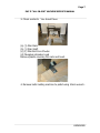
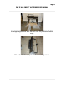
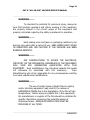
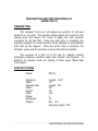
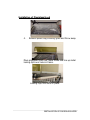
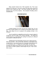
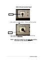
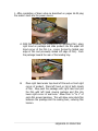
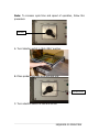
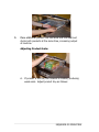
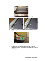
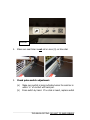
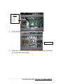
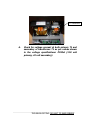
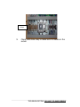
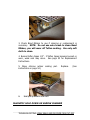
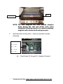
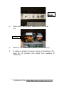
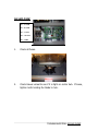
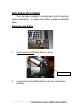
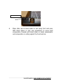
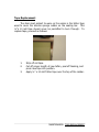
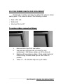
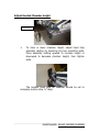
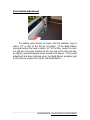
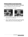
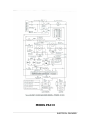
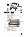
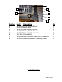
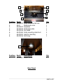
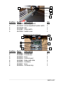
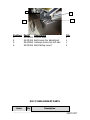
1
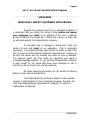
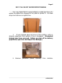
Page 1
PAC II “ALL-IN-ONE” MACHINE SERVICE MANUAL
OPERATION
MANUAL
Model PAC II
620 South 1325 West
Orem, Utah 84058
PHONE (801) 225-8040
FAX (801) 226-1509
_____________________________________________________________
IMPORTANT - PLEASE READ THIS CAREFULLY
The development of a good safety program, that is rigidly
enforced, is absolutely imperative when involved in the operation of
industrial equipment. Our machinery is well designed and includes
extremely important safety features. The part you the user play
through proper installation and maintenance procedures is of far
greater significance than our designs.
Only properly trained
individuals following rigidly enforced safety rules, as recommended
by A.N.S.I. and O.S.H.A., should be allowed to operate these
machines.
SAFETY PRECAUTIONS
1.
To avoid damage to the machine and injury to the
operator, DO NOT use liquids of any kind: flammable
materials, explosive materials, materials under extreme
pressure, pressurized gases, volatile powders, or bulk
materials that could fall through holes in grate, or any
materials and/or products not listed but which could
cause harm to operator.
2.
Do not touch the band ribbon soon after sealing due to
residual heat that may burn.
3.
Do not touch the heater cover plate while machine is
on.
4.
Do not touch the fan while in operation or use machine
without grate in place.
TABLE OF CONTENTS
___________________________________________________________
Preface
Unpacking
Warranty Notice
Warranty
Warranty Exceptions
Warnings
6-9
10
11-12
13
14-16
PAC II Instructions
Description and Specifications
Installation and Basic Set-Up
Installation of Film Rack
Installation of Plexiglass Hood
Mounting Film
Pin Perforator
Product Tray
Film Threading Diagram
Front Panel
Sequence of Operation
Adjusting product grate
Troubleshooting
No Heat to Band Ribbon
Weak Seals/Poor Cut Off
Magnet Won’t Hold on Chamber
No Air Flow
Maintenance
Band ribbon replacement
Tape replacement
Silicone seal pad replacement
Adjust height of hooded chamber
Pulse switch adjustment
Magnets adjustment
Replace transite bars
Electrical Panel Diagram
Electrical Schematic – PP43ST
Parts Nomenclature
Replacement Parts List
Spare Parts List
17
18-19
20
21-22
23
24
25
26
27-29
30-35
35-36
37-50
37-42
43-44
45-46
47-48
49
50-52
53
54
55
56
57
58
59
60
61
62-71
72
Page 5
PAC II “ALL-IN-ONE” MACHINE SERVICE MANUAL
UNPACKING
THOROUGHLY INSPECT EQUIPMENT UPON ARRIVAL.
If goods are received short or in a damaged condition, it
is important that you notify the carrier’s driver before he leaves
your company and insist on a notation of the loss or damage
across the face of the freight bill. Unless this is done, no claim can
be enforced against the transportation company.
If concealed loss or damage is discovered, notify the
carrier at once and insist on an inspection. This is absolutely
necessary! A concealed damage report must be made no later than
ten (10) days from the date the shipment was delivered. Unless you
do this, the carrier will not consider any claim for loss or damage.
The carrier’s agent will then make an inspection and grant a
concealed damage notation. If you give the transportation company
a clear receipt for the goods that have been damaged or lost in
transit, you do so at your own risk and expense.
All claims must be filed within six (6) months of delivery
date or carrier will not accept them.
Traco Manufacturing is willing to assist in every possible
manner to collect claims for loss or damage; however, this does not
hold Traco Manufacturing responsible for collection on claims or
replacement of material.
UNPACKING
Page 6
PAC II “ALL-IN-ONE” MACHINE SERVICE MANUAL
Your new Model PAC II comes bolted to a pallet and has a triwalled corrugated box strapped to the pallet to protect it. Cut steel
straps and remove corrugated box.
1.
If your machine does not arrive in this condition, write on
shipping paperwork that outside of box is damaged. (Concealed
damage may have occurred. Before you sign off on delivery
paperwork, open box and inspect for damage.)
2.
Remove
protective
plastic
covering
from
machine.
UNPACKING
Page 7
PAC II “ALL-IN-ONE” MACHINE SERVICE MANUAL
3. Check contents. You should have
(a) (1) Film Rack
(b) (1) Film Shaft
(c) (2) Film Roll Core Chucks
(d) Plexiglass chamber hood
Remove plastic covering film rack and hood.
4. Remove bolts holding machine to pallet using 10mm wrench.
UNPACKING
Page 8
PAC II “ALL-IN-ONE” MACHINE SERVICE MANUAL
Unwrap plexiglass hood and film rack from the protective bubble
wrap.
Film rack includes rack, roll shaft, 8 mounting screws.
IMPORTANT WARRANTY NOTICES
OPERATING AND MAINTENANCE MANUAL
The operating and maintenance manual has been
carefully prepared to provide the user with all the information needed
to properly install, operate, and maintain your Traco Manufacturing
equipment.
Please read this manual carefully and refer to it for
information on the care and use of your Traco Manufacturing
equipment. It is recommended that additional copies be ordered for
use by production, maintenance, and supervisory personnel.
Although the design of this equipment incorporates safeguards to
protect personnel, care should be used in operating, adjusting, and
servicing.
Attention is directed to the warranty which accompanies
all your Traco Manufacturing equipment. The terms and conditions
of this warranty apply only to unmodified units. Any unauthorized
modifications to the equipment automatically voids this
warranty.
Traco Manufacturing provides a one year warranty
on parts, excluding shipping or freight costs for replacement
parts. All warranty parts are shipped F.O.B. Orem, Utah.
Page 10
PAC II “ALL-IN-ONE” MACHINE SERVICE MANUAL
TRACO MANUFACTURING
WARRANTY
Traco Manufacturing, Inc. warrants each new product
manufactured to be free from defects in material and workmanship
for a period of (1) year from date of shipment by Traco
Manufacturing.
This warranty is not transferable with any subsequent resale.
Defective parts under warranty must be returned to Traco
Manufacturing freight prepaid. TRACO’s sole obligation and
purchaser’s sole remedy in the event of a warranty dispute shall be,
at TRACO’s option, to repair or replace the part in question. Labor
incurred in removing or installing the defective part is not covered by
this warranty. Prior to returning any parts for any reason, contact
Traco Manufacturing for a Return Authorization Number. This number
must accompany all returns.
This warranty shall not apply if equipment has been tampered
with, misused, improperly installed, altered, or has received damage
due to abuse, carelessness, accident or failure to follow
recommended regular maintenance procedures or has been serviced
by someone other than a duly authorized factory representative
without the express written consent of Traco Manufacturing, Inc.
This warranty is in lieu of all other warranties, expressed or
implied, including but not limited to warranties of merchantability and
WARRANTY
Page 11
PAC II “ALL-IN-ONE” MACHINE SERVICE MANUAL
fitness for a particular purpose, non-infringement or any other
matter.
Traco Manufacturing shall have no liability to any person for
direct, indirect, incidental or consequential damages or delay
resulting from any defect negligence, or tort and customer hereby
waives for itself any and all claims for punitive damages and all
claims of negligence of strict liability or both. In no event shall our
liability exceed the purchase price of the product that was actually
paid.
Traco Manufacturing reserves the right to make changes,
additions, or improvements to our products with no obligation to
make such changes in any previously shipped product covered by this
warranty.
Traco Manufacturing shall not be held liable for any damages
arising out of or in connection with the operation of the equipment
should customer or its agent fail to maintain equipment in safe
operating condition. This warranty shall become unenforceable if and
to the extent the customer or its agents remove, disconnect, or
otherwise render useless any safety device and/or parts designed or
affixed by us or fails to maintain and service equipment in a manner
as advised.
Traco Manufacturing provides a one-year warranty on parts,
excluding shipping or freight costs for replacement parts. All
warranty parts are shipped F.O.B. Orem, Utah. Service Labor
to install part is not covered under warranty!
WARRANTY
Page 12
PAC II “ALL-IN-ONE” MACHINE SERVICE MANUAL
WARRANTY EXCEPTIONS
The following sealer parts are considered to be consumable and
not under warranty:
1.
2.
3.
4.
Silicone Sponge
Band Ribbon
Teflon Tapes
Transite Channels/Band Holder
WARRANTY EXCEPTIONS
Page 13
PAC II “ALL-IN-ONE” MACHINE SERVICE MANUAL
WARNINGS
Every effort has been taken to ensure your safety while
operating this machine; however, there still remain certain risks. Do
not allow this machine to be operated before informing all personnel
of the following warnings.
WARNING........
Do not tamper with the electrical wiring. Only use a
licensed electrician for maintenance. Always disconnect the electrical
power before attempting any maintenance to all electrical and/or
moving parts.
WARNING........
In order to prevent injury to personnel and/or machinery
DO NOT INCREASE SETTINGS OR RATINGS ON EITHER ELECTRICAL
OR MECHANICAL OVERLOAD SAFETY DEVICES.
WARNING........
KEEP HANDS AWAY FROM MOVING CONVEYORS AND
ASSEMBLIES. Conveyor belts that have become worn or frayed are
capable of being hazardous. They should be replaced promptly.
WARNING........
NEVER OPERATE THIS OR ANY MOVING EQUIPMENT
WITHOUT ALL COVERS AND GUARDS IN PLACE. The internal
mechanism of most packaging machinery contains numerous shear,
pinch, and inrunning nip points, many of which are capable of
causing
severe
injury
and/or
permanent
disfigurement.
WARNINGS
Page 14
PAC II “ALL-IN-ONE” MACHINE SERVICE MANUAL
WARNING........
To minimize the potential for personnel injury, always be
sure that machine operators and others working on the machinery
are properly trained in the correct usage of the equipment and
properly instructed regarding the safety procedures for operation.
WARNING........
Heat sealing arms and jaws on packaging machinery can
become very warm after a period of use. KEEP HANDS AWAY WHILE
IN OPERATION AND USE CAUTION IF THE MACHINE HAS BEEN
RUNNING RECENTLY.
WARNING........
ANY MODIFICATIONS TO EITHER THE ELECTRICAL
CIRCUITRY OR THE MECHANICAL ASSEMBLIES OF THE MACHINERY
WILL VOID ANY WARRANTIES ASSOCIATED WITH THIS
EQUIPMENT. Such modifications may introduce hazards that would
not otherwise be associated with this machinery.
Traco
Manufacturing will not be responsible for any consequences resulting
from such unauthorized modifications.
WARNING........
The use of certain types of plastic films in sealing
and/or shrinking equipment may result in the release of
HAZARDOUS FUMES due to the degradation of the film at high
temperatures. Before using any plastic film in this equipment,
the manufacturer or supplier of the film should be contacted for
specific information concerning the potential release of
hazardous fumes. ADEQUATE VENTILATION MUST BE
PROVIDED AT ALL TIMES.
WARNINGS
WARNING........
machine
It is important that the machine operator unplug the
when he/she has finished operating the unit.
WARNINGS
DESCRIPTION AND SPECIFICATIONS OF
MODEL PAC II
DESCRIPTION
This compact “all-in-one” unit allows the operator to seal and
shrink all in one step. The operator simply places the product in the
sealing area and lowers the hood to apply the seal pressure
necessary to cut the film. Once the seal cycle is complete, the
operator releases the handle and the shrink chamber is automatically
held shut by the magnet. Once the shrink time is complete, the
chamber opens and the operator removes the finished product.
The purpose of a PAC II is for low to medium volume
packaging requiring excellent seals and minimal maintenance. It
features an impulse mode for sealing of films using “Band Seal
Technology.”
SPECIFICATIONS
Model:
PAC II
Seal Area:
Width:
Machine Size:
Width:
Height:
Volts:
Phase:
Amperage:
Weight:
Length: 18.5”
12”
Length: 49”
26”
45”
110
1
20
Net 215
Shipping weight 275
DESCRIPTION AND SPECIFICATIONS
INSTALLATION AND BASIC SET-UP
OF MACHINE
IMPORTANT
Read this manual carefully, and make it available to
everyone connected with the supervision, maintenance, or production
of this machine. Additional copies are available at your request.
(Contact your distributor for this information.) Be very careful when
operating, adjusting, or servicing this equipment. If in doubt, stop
and obtain qualified help before proceeding.
INSTALLATION OF PAC II
Place the PAC II in the desired location with the required
electrical power source available. (See power requirements.) Make
certain that proper electrical wiring is provided to guard against low
voltage. If the voltage is too low, the equipment will not function
properly.
Finding the proper location is a most important function
of the initial set-up.
One must take several factors into
consideration:
1.
2.
3.
4.
5.
Adequate power source.
Relationship to source of product.
Relationship to machine.
Relationship to any conveyors necessary to remove
finished product.
Convenience of operator.
The PAC II machine comes complete with power cord and
110 volt plug. Simply plug machine into 110 volt outlet. Make sure
you have no other machine connected to this power
source. If there is any doubt, get qualified assistance to do the
initial installation. Do not take any chances
INSTALLATION AND SET UP
Do not attempt to install, adjust, or operate this machine
without first reading the contents of this manual. Although the
design of the equipment incorporates safeguards to protect operating
and maintenance personnel, care should be used in operating,
adjusting, and servicing.
INSTALLATION AND SET UP
Installation of film rack
1.
Remove bubble wrap on film rack as shown.
2.
Hold film rack and slide bearing to the far left side
exposing mounting hole for screw. Tighten firmly.
Slide film rack to the far left side to expose mounting holes on right
side. Tighten firmly.
INSTALLATION OF FILM RACK
Installation of Plexiglass Hood
4.
Remove plastic bag covering grate and throw away.
Place plexiglass hood over metal frame and line up metal
locking clips over holes in frame.
Locking clips hold hood in place.
INSTALLATION OF PLEXIGLASS HOOD
Push down firmly and evenly by hand to secure metal
clips snap into holes.
INSTALLATION OF PLEXIGLASS HOOD
MOUNTING FILM
Select the proper width of center-fold film for the item being
packaged, allowing for width and height of package. With the
package properly positioned within the film in the sealing area,
allow sufficient film to overlap the sealing bars so that a seal
may readily be made without any possibility of open areas due
to insufficient film.
Place film roll on shaft using the two core chucks
provided to locate film. Tighten core chucks. The center-fold
is to be placed away from the operator, toward the rear of the
machine. Position film roll on shaft and tighten film core chuck
to hold film roll in position.
Thread film through the two pin perforator wheels
provided. Note that the perforator wheel turns freely and is not
binding.
Once threaded, separate film top from bottom and insert
product tray between. Make sure that the center-fold of film is
placed at the rear of the product tray. This allows the operator
to insert product between the layers of film on the product tray
and to prepare to move product and film into the sealing area.
When threading film, make sure the pull more than sufficient
film through the rollers, across the product tray, and into the
sealing area to ensure sufficient film to begin operation
MOUNTING FILM ROLL
Place product toward rear of film separator tray. Then move
product into seal area. Be sure to leave the bag loose around the
product when making the seal. This helps eliminate the seals from
blowing out in the shrink chamber. This completes threading and/or
mounting film.
PIN PERFORATOR
Located between the film roll and the product tray, the pin
perforator creates holes for air to escape as the operator pulls on the
film. This allows the air to escape as the package shrinks in the
chamber.
The pin perforator is adjustable and must be properly placed in
conjunction with the width of the desired package. The positioning
should always be re-evaluated when setting the machine for different
size product or different size film.
Adjustments to Pin Perforating wheels can be made using the
Allen key provided. The Pin Perforator assembly is composed of two
components: (1) wheel with pins and (2) grooved wheel without pins
on a concentric cam. To adjust pin wheels depth, use Allen key
provided and adjust wheel without pins using the concentric cam to
turn wheel on shaft to position wheel deeper into pins. Then re-lock
Allen screws.
PIN PERFORATOR
PRODUCT TRAY
The product tray is an adjustable metal platform used to
separate film and to insert product between top and bottom
layers of film.
INSTALLATION OF PRODUCT TRAY
FILM THREADING DIAGRAM
Product Tray
= Film
FILM THREADING DIAGRAM
PAC II Front Control Panel
Off Position
• Main switch is in OFF position. Machine will not operate.
Seal Only
ON 1
• Main switch in SEAL ONLY position. Machine will only
seal product NOT shrink.
NOTE: When the switch is in the seal only position,
the heater in the chamber is off.
CONTROL PANEL
Seal and shrink
Main switch in SEAL and SHRINK position, both functions are
available. Machine will take approximately 10-15 minutes to warm
up. You will know it is ready when chamber temperature thermostat
goes off.
CONTROL PANEL
Chamber Temperature
Control
Seal Time
1.
2.
3.
Shrink Timer
Chamber Temperature: How hot chamber will become.
Recommended settings for PVC Film: 260-280 Degrees
Recommended settings for Polyolefin Film: 300 Degrees
Note: These are only a suggested starting point when setting
up your machine. These settings will vary depending
on the shape of your product and the film thickness
used. Remember that thinner gauge films require less
heat and less shrink time.
Shrink Time: Amount of time the air will blow in chamber.
Recommended setting for PVC Film: 3-5
Recommended setting for Polyolefin Film: 3-5
Note: These are only a suggested starting point when setting
up your machine. These settings will vary depending
on the shape of your product and the film thickness
used. Remember that thinner gauge films require less
heat and less shrink time.
Seal Time: Amount of time band ribbon heats up.
Recommended setting for PVC: .6 to 1 seconds
Recommended setting for Polyolefin: .5 to .8 seconds
Note: The proper seal time is the shortest time possible to
cleanly seal and cut your film. Always start with a
shorter seal time where the film will NOT cut cleanly,
then increase dial setting to achieve desired results.
CONTROL PANEL
SEQUENCE OF OPERATION
A.
Product is placed on the film separator tray.
B.
The product tray functions as a means to separate the film,
allowing placement of product between upper and lower
portions of the film.
C.
Move product into seal area by pushing the product to the left.
D.
Manually pull the hooded chamber down. As the chamber
meets the lower switch seal band ribbon, the machine
automatically activates the band ribbon. *
NOTE:
If too much tension is on the film while the bag is
being made, the seals will, more than likely, be
weak or will “blow out” in the seal area while the
shrinking process is occurring. Make sure to relax
the film tension prior to sealing.
E.
The operator simply pulls down the hooded chamber using the
handle in front. Once the magnets lock they will apply the
proper seal pressure required. Once the seal time is complete,
the magnet will release the hood.
F.
At this point, the hooded chamber will stay down automatically
during the shrink cycle because the magnet is activated. When
the shrink timer is complete, the magnet releases the chamber
and it automatically raises allowing the operator to remove the
completed product.
SEQUENCE OF OPERATION
SEQUENCE OF OPERATION
1. After completion of basic setup as described on pages 16-29 plug
the sealer’s cord into the power source.
A. With film threaded (see instructions for mounting film), place
right hand on package and slide product into the upper left
hand corner of the film (i.e., corner formed by folded rear
edge of film and previously sealed left edge of film). Push
the package toward the rear of the loading tray.
B.
Place right hand under top sheet of film and on front right
corner of product. Place left hand on tail of both sheets
of film. Now push the package with right hand and pull
the film with left hand moving package and film into
lower right corner of seal area. Allow from ½” to 1” of
extra film around package. This will allow some slack film
between the package and the sealing bars, reducing film
tension.
SEQUENCE OF OPERATION
C. Press hooded chamber handle down. Magnetic lock will hold
hooded chamber down and apply necessary pressure to produce seal
for duration of seal cycle time set.
D. Shrinking chamber hood will automatically stay down during shrink
cycle by use of the magnetic hold-down. Operator is free to get next
package ready to seal.
SEQUENCE OF OPERATION
E.
Once shrink cycle time is complete, operator may remove
Completed product from chamber
SEQUENCE OF OPERATION
Note: To increase cycle time and speed of operation, follow this
procedure:
Seal Only
A. Turn Selector switch to SEAL ONLY position.
B. Place product into seal area and seal only.
Seal and Shrink
C. Turn selection switch to seal and shrink.
SEQUENCE OF OPERATION
D.
Place additional product into seal area and now seal and
shrink both products at the same time, increasing output
of machine.
Adjusting Product Grate:
A. If product is too tall, film tension is created, producing
weak seals. Adjust product tray as follows:
SEQUENCE OF OPERATION
Remove grate to gain access to adjusted studs.
B.
Adjust grill, move screws downward into lower threaded
hole.
C.
Product now sits half way below seal pad. This will
reduce film tension when sealing and place seal in center
of package.
SEQUENCE OF OPERATION
TROUBLESHOOTING
The following guidelines are provided to aid in determining the
source of any operation difficulties which may develop.
In
performing the tests and checks which follow, carefully inspect for
any loose components, broken or loose wires, poor electrical
connections, etc., while testing the various switches, controls, relays,
transformers, etc. For checking electrical problems, use a voltage
meter.
Note: While troubleshooting use caution to avoid danger of
electrical shock. When power is not required for
checking for the presence or value of voltages used,
always have it disconnected.
DISCONNECT ALL POWER BEFORE MAKING ANY REPAIRS.
REFER TO ELECTRICAL BOARD LAYOUT AND ELECTRICAL
SCHEMATIC FOR LOCATION OF ELECTRICAL COMPONENTS
NO HEAT TO BAND RIBBON
Off Position
1.
Check that the sealer is plugged in and that power is present at
the socket. Make sure the power switch is in the SEAL ONLY or
SEAL AND SHRINK position.
TROUBLESHOOTING: NO HEAT TO BAND RIBBON
Seal Timer
2.
Make sure seal timer is not set on zero (0) on time dial.
3.
Check pulse switch adjustment.
(a)
(b)
Make sure switch is being activated when the seal bar is
within ¼” of contact with seal pad.
Press switch by hand. If no click is heard, replace switch.
TROUBLESHOOTING: NO HEAT TO BAND RIBBON
PP48ST
F1-15 Amp
F2- 20 Amp
F3-1 Amp
F4-20 Amp
F5-1 Amp
4.
Check all fuses.
CR1 Contactor
5.
Check to see CR1 contactor is ok and the points are not burned
or no wire has come loose.
TROUBLESHOOTING: NO HEAT TO BAND RIBBON
T1 Transformer
6.
Check for voltage present at both primary T1 and
secondary of transformer T1 as per values shown
in the voltage specifications: PP43st (110 volt
primary, 42 volt secondary).
TROUBLESHOOTING: NO HEAT TO BAND RIBBON
7.
Check for broken band ribbon inside or outside the corner
Bead.
8. Check for bad connections on each end of band ribbon.
sure wires are connected to each end of compensator.
Make
TROUBLESHOOTING: NO HEAT TO BAND RIBBON
Solid State
Relays
9.
Check solid state relay to make sure it is secure in the
socket.
TROUBLESHOOTING: NO HEAT TO BAND RIBBON
WEAK SEALS AND/OR POOR FILM CUT OFF
Seal Timer
1.
Improper setting of seal timer.
proper adjustment.
Refer to page 29 for
2.
Improper operating technique. Too much film tension,
make sure film is relaxed prior to sealing.
TROUBLESHOOTING: WEAK SEALS AND/OR POOR FILM CUT-OFF
3. Check Band Ribbon to see if cleaning or replacement is
necessary. NOTE: Do not use wire brush to clean Band
Ribbon, you will wear off Teflon coating. Use only soft
cloth to clean.
4. Burned teflon tapes 1/2”. If teflon tapes become burned or
worn, weak seal may occur. See page 53 for Replacement
Instructions.
5. Wavy silicone rubber sealing pad.
instructions on page 54.)
6.
Replace.
(See
Seal pad pressure incorrect.
MAGNETIC HOLD DOWN ON SHRINK CHAMBER
TROUBLESHOOTING: WEAK SEALS AND OR POOR FILM CUT OFF
Magnet
Single Magnet
NOTE: The dual magnets will hold hooded chamber
down during the seal and shrink cycle. Once
completed allowing operator to remove package,
magnets will release and hood pops open.
1.
Seal head will not stay down – machine operates normally
otherwise.
F1 – 15 AMP
F2 – 20 AMP
F3 – 1 AMP
F4 - 20 AMP
F5 – 1 AMP
(a)
Check Fuses F1 through F5. Replace if burned.
TROUBLESHOOTING: WEAK SEALS AND OR POOR FILM CUT OFF
Shrink Time
Not at Zero
2.
Check shrink (Time) setting. Make sure it is not set at
zero.
T2 Transformer
3.
Check for 110 volts PP43ST or primary transformer (T2).
4.
If voltage is present to primary winding of transformer (T2),
check for 24 (nominal) volts output from secondary of
transformer.
TROUBLESHOOTING: WEAK SEALS AND OR POOR FILM CUT OFF
NO AIR FLOW
F1 – 15 AMP
F2 – 20 AMP
F3 – 1 AMP
F4 – 20 AMP
F5 – 1AMP
1.
Check all fuses.
2.
Check blower wheel to see if it is tight on center hub. If loose,
tighten bolts holding fan blade to hub.
TROUBLESHOOTING: NO AIR FLOW
2.
Remove bottom cover from underside on machine.
3.
Check Blower motor to make sure no wires are loose.
4.
Check capacitor and replace if bad
5.
Check blower motor and replace if bad.
TROUBLESHOOTING: NO AIR FLOW
MAINTENANCE
1.
Before working on machine, switch machine off and
disconnect power cord from wall outlet.
2.
Clean Band Ribbon using soft cloth by wiping Band
Ribbon when warm, as it is easier to remove any
residue while Band Ribbon is warm.
3.
If lower chamber requires cleaning where fan wheel is,
we recommend using a vacuum cleaner to remove any
particles that may have fallen into the chamber.
4.
We recommend you use a glass cleaner to clean the
plexiglass hood. Do not use solvents.
MAINTENANCE: BAND RIBBON REPLACEMENT
BAND RIBBON REPLACEMENT
The band ribbon is subject to constant wear and will eventually
require replacement. To replace band ribbon, proceed as described
below.
Replacing Band Ribbon
1.
Loosen screw holding Band Ribbon in corner.
Band Ribbon screw
2.
Loosen screw holding Band Ribbon inside rear compensator
assembly.
MAINTENANCE: BAND RIBBON REPLACEMENT
3.
Loosen screw holding Band Ribbon in front compensator
assembly.
4.
Use pre-cut Band Ribbon and place piece of teflon tape (½”L x
¼”W x 3 mill) around corner of band ribbon to insulate Band
Ribbon from brass corner block. Install Band Ribbon on corner
first then insert into each end of front and side compensator.
Band Ribbon may be oversized slightly, if so, cut to fit
ends.
5.
Compensators are spring loaded. Use screwdriver to push in –
flush to transit bars before fastening.
MAINTENANCE: BAND RIBBON REPLACEMENT
Compensator Screw
6.
Place other end of band ribbon in slot along front seal area.
With band ribbon in slot, use screwdriver to move front
compensator forward until band ribbon is inside compensator
and compensator is resting against the front seal bar.
MAINTENANCE: BAND RIBBON REPLACEMENT
Tape Replacement
The item most subject to wear on the sealer is the teflon tape
used to cover the silicone sponge rubber on the sealing bar. This
½”x 10 mill tape should never be permitted to burn through. To
replace tape, proceed as follows:
1.
2.
3.
Strip off old tape.
Cut off proper length of new teflon, peel off backing, and
press new tape into position.
Apply ½” x 10 mill Teflon tape over the top of the rubber.
MAINTENANCE: TAPE REPLACEMENT
SILICONE RUBBER SEALING PAD REPLACEMENT
Occasionally it will be necessary to replace the silicone rubber
sealing pads. This should be done if the following is noted:
• Gaps in the seal
• Weak seals
• Improper film cut-off
To replace rubber, proceed as follows:
1.
2.
3.
4.
Remove teflon tape from seal rubber.
Seal pads are designed with a channel for easy
replacement. Pull silicone rubber out of the channel.
Replace with new silicone rubber. Press rubber back into
channel using a double-sided tape to hold rubber in
position.
Install ½” - 10 mill teflon tape on top of rubber.
MAINTENANCE: SEALING PAD REPLACEMENT
Adjust Hooded Chamber Height
Hood casting
1.
To raise or lower chamber height, adjust hood stop
assembly casting by loosening the two mounting bolts.
Move assembly casting upward to increase height or
downward to decrease chamber height, then tighten
bolts.
The bracket hood stop on chamber should be set to
compress cushion stop ½” deep.
MAINTENANCE: ADJUST HOODED CHAMBER
Pulse Switch Adjustment
The sealing cycle should not begin until the chamber hood is
within 1/4” or less of the film to be sealed. If the Band Ribbon
energizes before the hood is within 1/4” of the film, loosen the locknut and turn the screw (located at the rear end of the side seal bar)
up slightly (counterclockwise when viewed from above). The correct
adjustment has been obtained when the Band Ribbon energizes just
as the seal bar comes into contact with Band Ribbon.
MAINTENANCE: PULSE SWITCH ADJUSTMENT
Adjustment of Magnets for Correct Chamber Pressure
All magnets have been factory adjusted for equal sealing
pressure throughout the length of both the front and side seal bars.
However, if an adjustment is required, proceed as follows:
1.
Disconnect the sealer’s power source.
2.
Loosen the two upper magnet bolts. Magnets settle to their
lowest position in the mounting slots.
3.
Lower the chamber handle fully and set the upper mounting
bracket to within 1/16” from the lower magnet. Tighten the
mounting bolts securely to retain the proper adjustment.
MAINTENANCE: MAGNET ADJUSTMENT
Replacing Front and Side Transite Bars
1.
Turn power switch to OFF position.
Film Support Bracket
2.
See instructions on replacing Band Ribbon on page 49.
Transite Bar Holding
Screw
(a)
(b)
(c)
(d)
Remove film support bracket which is mounted next to
transite holding channel.
Remove screws holding transite bars in channel.
Transite Bar can now be removed from channel. Reinstall
new bar.
See page 50 for instructions on installing new band
ribbon.
MAINTENANCE: REPLACING TRANSITE BARS
ELECTRICAL PANEL DIAGRAM
T2
T1
Fuses
F1
F2
F3
F4
Control Unit
PPT 05
CR1
SSR1
SSR2
Terminal
Strip
ELECTRICAL PANEL DIAGRAM
MODEL PAC II
ELECTRICAL DRAWING
Item
S1
TC1
CR1
F1
F2
F3
F4
F5
T1
T2
SSR1
SSR2
PPT-05
MS1
PL1
PL2
M1
MG1
MG2
HT1
C1
Part#
48-E2060
48-E355110
48-E2015
48-E2040
48-E2025
48-E2042
48-E2025
48-E2042
48-E2095
48-E2085
48-E2065
48-E2065
48-E2075
48-E2085
48-E2090
48-E2095
48-M3005
48-M3010
48-M2040
48-M2035
48-E2005
Qty
Parts List Nomenclature
1
1
Main Switch
Temperature Control
1
1
1
1
2
2
1
1
1
1
1
1
1
1
1
1
1
2
1
Contactor
Fuse – 15 AMP
Fuse – 20 AMP
Fuse – 1 AMP
Fuse – 20 Amp
Fuse – 1 Amp
Pulse Transformer
Step Down Transformer
Solid state relay
Solid state relay
Control unit
Pulse Switch
Power Indicator Light
Sealing Indicator Light
Fan Motor
Magnet – Right
Magnet – Left
Heater Bank
Capacitor – Blower Motor
ELECTRICAL DRAWING
Parts List
8
7
3
4
5
2
1
Position
1.
2.
3.
4.
5.
6.
7.
8.
6
Part#
48-M1085
4848-M3025
48-M1090
48-M1045
1519-015
48-M2036
48-M2061
Description
Legs
Main frame
Plexiglass hood
Loading tray
Film rack assembly-complete
Casters-locking
Handle
Sponge
Qty
4
1
1
1
1
4
1
1
3
4
1
2
Position
1.
2.
3.
4.
Part#
48-E3010
48-M3064
48-M3020
48-M3063
Description
Magnets-Lower
Film lift channel-front
Grate
Film lift channel-side
Qty
2
1
1
1
3
PARTS LIST
2
4
5
1
6
7
8
Position
1.
2.
3.
4.
5.
6.
7.
8.
Part#
48-M3065
48-M1000
48-M1020
48-M3052
48-M3054
1519-028
48-M3056
48-M3042
Description
Front transite channel
Band ribbon
Side-transite channel
Screw-film lift channel
Screw-transite mounting
Corner block
Allen bolt-band ribbon corner lock screw
Screw-corner block mounting screws
Qty
1
1
1
4
4
1
1
1
Hooded Chamber
PARTS LIST
1
3
2
4
5
7
6
8
Position
1.
2.
3.
4.
5.
6.
7.
8.
Part#
48-M1075
48-M
48-M3017
48-M3018
48-M3016
48-M1065
48-M3030
48-M3016
Description
Grate mounting bkt-rear
Metal mesh cover
Insulation
Metal base plate
Fan blade
Grate mounting stub-Front
Hub fan mounting
Felt lining
Qty
2
1
1
1
1
2
1
1
1
Position
1.
Part#
Description
48-E3005 Blower motor
Qty
1
Rear Panel
PARTS LIST
1
2
Position
1.
2.
3.
3
Part#
48-M3043
48-M2020
48-E2045
Description
Screw-panel
Panel
Power cord
Qty
8
1
1
2
1
Position
1.
2.
Part#
Description
1519-177 Compensator assembly-rear
48-M3060
Torsion bar
Qty
1
1
Control Panel
PARTS LIST
4
5
3
6
2
1
Position
1.
2.
3.
4.
5.
6.
Part#
48-M1060
48-M3043
48-E2060
48-E3046
48-E3046
48-E355-110
Description
Front plate-control panel
Screw-face plate mounting screw
Switch-main power
Seal timer-Potentiometer
Shrink timer-Potentiometer
Temperature control
Qty
1
6
1
1
2
1
Hole Punch
1
3
2
Position
1.
2.
3.
Part#
48-M1120
48-M3040
48-M3041
Description
Mounting shaft
Sponge wheel
Pin wheel
Qty
2
2
2
Pulse Switch
PARTS LIST
3
1
2
4
5
Position
1.
2.
3.
4.
5.
Part#
48-M3035
48-M3047
48-M3048
48-E2085
48-M3061
Description
Mounting bracket
Screw-adjustment pulse switch
Nut
Pulse switch
Switch cover
Electrical Control Panel
Qty
1
1
1
1
1
2
1
4
3
8
5
6
Position
1.
2.
3.
4.
5.
6.
7.
8.
Part#
48-E2095
48-E2085
48-E2019
48-E2018
48-E2065
48-E2015
48-E2017
48-E2016
7
Description
Transformer
Transformer
Fuse
Control board
Relay-solid state
Contactor
Fuse
Terminal strip
Qty
1
1
4
1
2
1
1
1
PARTS LIST
1
3
4
2
Position
1.
2.
3.
4.
Part#
48-M1052
48-M1006
48-M3066
48-M1006
Description
Cushion stop
Bolt-torsion bar adjustment
Castings-torsion bar left side
Bolt-Casting mount
Qty
1
1
1
2
PAC II REPLACEMENT PARTS
PP48st
Qty
Description
PARTS LIST
Qty
Description
48-M1000
48-M1007
48-M3066
48-M1005
1
2
1
2
48-E2005
48-M3066
48-M1010
48-M3064
48-M3065
48-M3070
48-M3063
48-M3065
48-M1020
1519-176
1519-177
48-E2015
1
1
1
1
1
1
1
1
1
1
1
1
1
1
1
1
1
1
1
1
1
2
1
1
2
2
2
1
2
2
2
1
1
1
1
Band Ribbon
Bolt-casting mount
Bolt-torsion bar adjustment
Brackets – Chamber Shaft Mounting
Bracket
Capacitor – Blower Motor
Casting-torsion bar adjustment
Chamber Height Adj. Assembly
Channel-front film lifter
Channel-front/aluminum channel holder
Channel-Side/aluminum channel holder
Channel-side film lifter
Channel – Transite – Front Blade Holder
Channel – Transite – Side Blade Holder
Compensator Assembly – Front
Compensator Assembly – Side
Contactor – CR1
Contactor-solid state
Control board
Corner Block – Brass
Cover-pulse switch
Cover – Heater Bank
Cushion stop assembly
Fan blade
Felt Padding – Chamber
Film Rack
Film Roll – Core Chucks
Film Separating Bar
Front Plate – Control Panel
Fuses – F1 and F4 (16 Amp)
Fuses (F3, F5) (1 Amp)
Fuses – F2 (20 Amp)
Grate
Grate – Mounting Bracket – Front
Grate – Mounting Bracket – Front – Screw
Grate – Mounting Bracket – Rear
Handle
Heater Bank
Hood – Plexiglass
Hub – Fan Mounting
PP48st
48-E2018
1519-028
48-M3061
48-M1040
48-M1052
48-M3015
48-M3016
48-M1045
48-M1050
48-M1055
48-M1060
48-E2040
48-E2042
48-E2025
48-M3020
48-M1065
48-M3021
48-M1075
48-M2036
48-E2035
48-M3025
48-M3030
PARTS LIST
PP48st
48-M1085
1519-015
48-M1090
48-E3010
48-M1100
48-M3004
48-M3005
48-M3035
48-M3048
48-M2020
48-M3040
48-M3041
48-E2045
48-E3046
48-E3046
48-M3043
48-M3043
48-M3047
48-M3042
48-M3045
48-M3050
48-M3055
48-M1115
48-M1120
48-M2061
48-E2060
48-E2085
48-M1125
48-E355-110
48-M3060
48-M1130
48-E2095
48-E2085
Qty
4
4
1
2
1
1
1
1
1
1
2
2
1
1
1
8
6
1
2
1
1
1
1
2
1
1
1
2
1
1
2
1
1
Description
Legs
Locking Casters
Loading Tray
Magnet – Seal and shrink-lower
Magnet – Upper Mounting Bracket
Metal mesh cover
Motor – Blower
Mounting Bracket – Pulse Switch
Nut-lock pulse adjust screw
Panel-rear access to electrical
Pin Perforator – sponge wheel
Pin Perforator – Pin Wheel
Power Cord
Potentiometer-seal time
Potentiometer-shrink time
Screw-back panel
Screw-face plate
Screw-pulse adjustment
Screws – Corner Block-Mounting
Seal Rubber – Top/Front
Seal Rubber – Top/Side
Shaft – Roll Holder
Shaft – Film Support
Shaft – Pin Perforator Support
Sponge
Switch – Main Power
Switch – Pulse
Teflon Tape ½” x 10 mill
Temperature Control
Torsion Bar
Track Bearings – Film Rack
Transformer – T1
Transformer – T2
PARTS LIST
Spare Parts List
PAC II
Item
#
1
2
3
4
5
6
7
8
9
10
Part #
48-E2042
48-E2040
48-E2025
48-1125
48-M3045
48M-3050
48M-1000
1519-028
48M-3065
48M1020
Description
Qty.
Fuse – F3, F5 - 1 AMP
Fuse –F1, - 15 AMP
Fuse – F2 - 20 AMP
½” x 10 mill x 10 yrd. Teflon tape
Seal Pad Rubber – Front
Seal Pad Rubber – Side
Band Ribbon
Corner Block
Channel – Transite – Front
Channel – Transite – Side
2
2
2
1
1
1
2
1
1
1
Total Cost
Price
1
$145.50
SPARE PARTS LIST