1
EST3
Installation and Service
Manual
P/N 270380 • Rev 7.0 • 10SEP07
DEVELOPED BY
GE Security, Inc.
8985 Town Center Parkway
Bradenton, FL 34202
(941) 739-4300
COPYRIGHT NOTICE
Copyright © 2007 GE Security, Inc.
This manual is copyrighted by GE Security, Inc. (GE Security).
You may not reproduce, translate, transcribe, or transmit any
part of this manual without express, written permission from GE
Security.
This manual contains proprietary information intended for
distribution to authorized persons or companies for the sole
purpose of conducting business with GE Security. Unauthorized
distrib ution of the information contained in this manual may
violate the terms of the distribution agreement.
TRADEMARKS
Microsoft, Microsoft Mouse, Microsoft Windows, Microsoft Word,
and Microsoft Access are either registered trademarks or
trademarks of Microsoft Corporation.
Content
Document history • iv
Important information • v
About this manual • ix
The EST3 library • xi
Related documentation • xii
Chapter 1
System overview • 1.1
System description • 1.2
Audio subsystem description • 1.6
Digital network subsystem • 1.16
Foreign language support • 1.22
Signature series devices • 1.26
Network applications • 1.29
Audio applications • 1.33
Firefighter phone system • 1.42
Chapter 2
Security applications • 2.1
Security equipment • 2.2
Certificate installations • 2.8
Multiple 3-MODCOM modules • 2.12
Multiple site security and access • 2.13
Multiple tenant security • 2.16
Secure access • 2.20
Chapter 3
Access control applications • 3.1
Access control equipment • 3.2
Anti-passback • 3.11
Central monitoring station • 3.14
Common door access • 3.16
Delayed egress • 3.18
Elevator control • 3.21
Emergency exit door • 3.24
Handicap access door • 3.26
Maglock peripherals • 3.28
Multiple card readers • 3.30
Muster • 3.32
Power for continuous locks • 3.35
Power for intermittent locks • 3.37
Power from an AC source • 3.39
Power from a remote source • 3.42
Remote controls • 3.45
Two-person rule • 3.47
Chapter 4
Centralized audio applications • 4.1
Equipment required • 4.2
ATPC Amplifier Terminal Panel Cabinet • 4.3
ATP Amplifier Terminal Panel • 4.6
Audio amplifiers • 4.8
URSM Universal Riser Supervisory Module • 4.10
EST3 Installation and Service Manual
i
Content
ATP external battery charger • 4.20
Amplifier backup • 4.22
Branch speaker wiring • 4.25
Troubleshooting • 4.27
Chapter 5
Installation • 5.1
Installation overview • 5.3
UL 864 NAC signal synchronization • 5.6
Creating an initial startup version of the project database • 5.16
System installation sequence • 5.18
Preliminary field wiring testing • 5.19
Chassis installation in EIA 19-inch racks • 5.22
ATCK Attack Kit for cabinets • 5.23
Local rail module installation • 5.24
3-MODCOM Modem Communicator module • 5.26
3-SAC Security Access Control module • 5.40
3-AADC1 Addressable Analog Driver Controller and IRC-3 • 5.41
AC power and DC battery wiring • 5.42
Connecting auxiliary/booster power supplies • 5.44
Connecting the PT-1S impact printer • 5.46
Adjusting amplifier output levels • 5.49
Connecting a CDR-3 Zone Coder for coded tone output • 5.50
Connecting an external modem for use with the Remote
Diagnostics Utility • 5.53
Running the RPM and distributing profiles • 5.55
Chapter 6
Power-up and testing • 6.1
Cabinet power-up procedure • 6.3
Runtime and system errors • 6.4
Initial and reacceptance test procedures • 6.6
Control and emergency communications equipment testing • 6.7
Detector, input module, and output module testing • 6.18
Initiating device testing • 6.21
Notification appliance testing • 6.23
Record of completion • 6.24
Chapter 7
Preventive maintenance • 7.1
General • 7.2
Preventive maintenance schedule • 7.3
Signature device routine maintenance tips • 7.5
Signature detector cleaning procedure • 7.6
System trouble and maintenance log • 7.7
Chapter 8
Service and troubleshooting • 8.1
Overview • 8.3
Hardware problems • 8.5
Modules • 8.7
Audio components • 8.20
Pseudo point descriptions • 8.24
Signature data circuit (SDC) operation • 8.35
Basic Signature data circuit troubleshooting • 8.37
Signature controller modules • 8.47
Device troubleshooting • 8.49
Signature diagnostic tools • 8.51
ii
EST3 Installation and Service Manual
Content
DSDC status • 8.65
Addressable analog diagnostic tools • 8.70
3-AADC1 Addressable Analog Driver Controller • 8.74
Addressable analog device troubleshooting • 8.75
Wiring problems • 8.77
Appendix A
System addresses • A.1
Address format • A.2
LRM addresses • A.4
Control / display module addresses • A.9
Device addresses • A.10
Appendix B
System calculations • B.1
Network data riser limits • B.2
Signature data circuit wire length • B.5
Notification appliance circuit calculations • B.11
25 or 70 Vrms NAC wire length • B.17
Addressable analog circuit wire length • B.19
Cabinet battery • B.20
SAC bus power • B.21
CPU memory • B.26
Fiber optic cable worksheet • B.28
Appendix C
Listing requirements • C.1
NFPA standards • C.2
Minimum requirements for UL security applications • C.3
UL and ULC requirements • C.10
Y
Glossary • Y.1
Z
Index • Z.1
EST3 Installation and Service Manual
iii
Content
Document history
Date
Revision
Reason for change
17JUL96
1.0
Initial release
31MAR97
1.5
Revised: detector cleaning procedure; CAB & RCC Cabinets;
download wiring; Compatibility info; Power supply specifications;
3-CPU wiring; System addressing; 3-IDC8/4 jumpers & wiring.
Added: power supply location information; 3-SSDC(1) Filter
Board; Humidity limits, Isolator limits.
14DEC98
2.0
Revised: 3-ASU & 3-RS485 specifications; Battery shelf data;
Module current draw; 3-CPU1 network wiring.
Added: 3-AADC module; CDR-3 Zone Coder; Centralized audio
components; Buffered RS-232 Communications Cable; PT-1S
switch settings; 3-FIB information; 3-TAMP(5); RACCR
Enclosure; SIGA-APS Power Supply; SIGA-AAxx Audio
Amplifiers.
21OCT99
3.0
Incorporated changes concurrent with software release version
1.5. Revised structure to reduce duplicate information.
30AUG01
4.0
Revised to incorporate security and access control integration.
29OCT01
5.0
Added Canadian security standards to Related Documents and
removed "Appendix D: System Compatibility".
17AUG04
6.0
Revised per 3-SDU release 3.3, 3.4, and 3.5.
21JUN07
7.0
Revised to conform to UL 864 9th edition requirements
iv
EST3 Installation and Service Manual
Content
Important information
Limitation of liability
This product has been designed to meet the requirements of
NFPA Standard 72; Underwriters Laboratories, Inc., Standard
864; and Underwriters Laboratories of Canada, Inc., Standard
ULC S527. Installation in accordance with this manual,
applicable codes, and the instructions of the Authority Having
Jurisdiction is mandatory. GE Security shall not under any
circumstances be liable for any incidental or consequential
damages arising from loss of property or other damages or losses
owing to the failure of GE Security products beyond the cost of
repair or replacement of any defective products. GE Security
reserves the right to make product improvements and change
product specifications at any time.
While every precaution has been taken during the preparation of
this manual to ensure the accuracy of its contents, GE Security
assumes no responsibility for errors or omissions.
FCC warning
This equipment can generate and radiate radio frequency energy.
If this equipment is not installed in accordance with this manual,
it may cause interference to radio communications. This
equipment has been tested and found to comply within the limits
for Class A computing devices pursuant to Subpart B of Part 15
of the FCC Rules. These rules are designed to provide
reasonable protection against such interference when this
equipment is operated in a commercial environment. Operation
of this equipment is likely to cause interference, in which case
the user at his own expense, will be required to take whatever
measures may be required to correct the interference.
Industry Canada information
Note: The Industry Canada label identifies certified equipment.
This certification means that the equipment meets certain
telecommunications network protective, operational, and safety
requirements. Industry Canada does not guarantee the equipment
will operate to the user’s satisfaction.
Before installing this equipment, users should ensure that it is
permissible to be connected to the facilities of the local
telecommunications company. The equipment must also be
installed using an acceptable method of connection. The
customer should be aware that compliance with the above
conditions may not prevent degradation of service in some
situations.
EST3 Installation and Service Manual
v
Content
Repairs to certified equipment should be made by an authorized
Canadian maintenance facility designated by the supplier. Any
repairs or alterations made by the user to this equipment, or
equipment malfunctions, may give the telecommunications
company cause to request the user disconnect the equipment.
Users should ensure for their own protection that the electrical
ground connections of the power utility, telephone lines, and
internal metallic water pipe system, if present, are connected
together. This precaution may be particularly important in rural
areas.
Caution: Users should not attempt to make such connections
themselves, but should contact the appropriate electric inspection
authority, or electrician, as appropriate
Note: The Load Number (LN) assigned to each terminal device
denotes the percentage of the total load to be connected to a
telephone loop that is used by the device, to prevent overloading.
The termination on a loop may consist of any combination of
devices subject only to the requirements that the sum of the Load
Numbers of all the devices does not exceed 100.
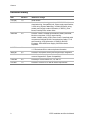
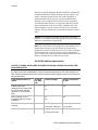
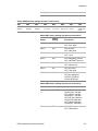
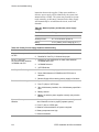
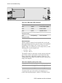
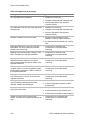
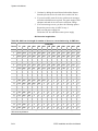
UL 864 9th edition requirements
NOTICE TO USERS, INSTALLERS, AUTHORITIES HAVING JURISDICTION, AND OTHER
INVOLVED PARTIES
This product incorporates field-programmable software. In order for the product to comply with
the requirements in the Standard for Control Units and Accessories for Fire Alarm Systems, UL
864, certain programming features or options must be limited to specific values or not used at all
as indicated below.
Programmable feature or
option
Permitted
in UL 864?
(Y/N)
Possible settings
Settings permitted in
UL 864
Enable Supervision
(telephone line is supervised
for ground faults, a single
open line, or a wire-to-wire
fault)
Y
No
Yes
DACT Settings - Line 2
Installed (single line or dual
line dialer)
Y
Trouble Resound (panel
resound)
Y
AC Power Delay
Y
Yes
No
Yes
Yes
Disabled (0)
Disabled [2]
1 second to ~99 hours
0 to 24 hours
Disabled
1 to 3 hours
1 minute to 45 hours
vi
EST3 Installation and Service Manual
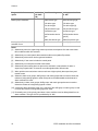
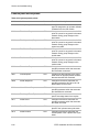
Content
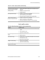
Programmable feature or
option
Permitted
in UL 864?
(Y/N)
Possible settings
Settings permitted in
UL 864
Event message routing
Y
All Cabinets
All Cabinets
No Cabinets
No Cabinets [3]
User defined routes (1
to 15)
User defined routes (1 to
15) [4]
Enabled
Enabled
Disabled
Disabled [5]
Delays (programmed in rules) Y
0 to 240 seconds
0 to 240 seconds [6]
CMS event reporting priority
(programmed in rules)
Y
1 to 255
1 to 255 [7]
CMS activate and restore
messages (programmed in
rules)
Y
Send on activation
Activation and
restoration triggers must
match the message type
4-state alarm IDC
N
N/A
In Signature module
configuation, personality
code 18 is prohibited
[11]
Alarm zone group members
Y
Alarm device type
Alarm device type [8]
Pull device type
Pull device type
Heat device type
Heat device type
Verified smoke device
type
Verified smoke device
type
Water flow device type
Water flow device type
Alarm device type
Alarm device type [8]
Pull device type
Pull device type
Heat device type
Heat device type
Verified smoke device
type
Verified smoke device
type [9]
Water flow device type
Water flow device type
Alarm zone device type
Alarm zone device type
Fire zone device type
Fire zone device type
Matrix group device
type
Matrix group device type
1 to 255
1 to 255 [10]
Event message display
filtering: Alarm, Supervisory,
and Trouble options
AND group members
AND group device activation
count
Y
Send on restoration
Y
Y
EST3 Installation and Service Manual
vii
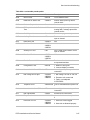
Content
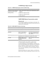
Programmable feature or
option
Permitted
in UL 864?
(Y/N)
Possible settings
Settings permitted in
UL 864
Matrix groups: Members
Y
Alarm device type
Alarm device type [8]
Pull device type
Pull device type
Fire device type
Fire device type [8]
Call point device type
Call point device type
Heat device type
Heat device type
Verified smoke device
type
Verified smoke device
type [9]
Water flow device type
Water flow device type
3 to 10
3 to 10 [10]
Matrix groups: Device
activation count
Y
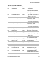
Notes
[1]
Allowed only when the supervising station supervises the telephone line and annunciates
fault conditions within 200 seconds
[2]
Allowed only on control panels that transmit trouble event signals off premises
[3]
Allowed only with monitor device types and switches
[4]
Allowed only if user route includes the control panel
[5]
Allowed only on nonrequired remote annunciators
[6]
Allowed only when setting does not prevent the activation or transmission of alarm or
supervisory signals within 10 seconds or trouble signals within 200 seconds
[7]
When priorities are used, alarm events must have a higher priority than supervisory and
trouble events.
[8]
Allowed in alarm zone groups, AND groups, and matrix groups that are used to initiate the
release of extinguishing agents or water except when the addressable smoke detector's
alarm verification is used.
[9]
Allowed only in alarm zone groups, AND groups, and matrix groups that are not used to
initiate the release of extinguishing agents or water
[10] A minimum device activation count of 2 is required if the AND group or matrix group is used
to initiate the release of extinguishing agents or water
[11] Personality code 18 is typically used when a short condition must be distinguished from an
alarm condition. This type of IDC is prohibited by UL 864.
viii
EST3 Installation and Service Manual
Content
About this manual
This manual provides information on how to properly install,
wire, and maintain the EST3 integrated system and related
components. This manual applies to the following EST3 models:
EST3
EST3R
EST3-230
EST3R-230
Organization
Chapter 1: System overview: a descriptive overview of the
components and subsystems that comprise an EST3 system.
Chapter 2: Security applications: covers security applications.
This chapter contains block diagrams that show the components
required to create specific security systems.
Chapter 3: Access control applications: covers access control
applications. Like Chapter 2, this chapter contains block
diagrams and descriptions of specific access control systems.
Chapter 4: Centralized audio applications: describes the
equipment and configuration required to create centralized audio
for a site.
Chapter 5: Installation: installation information for system
components and applications that supplement the instructions
provided on individual component installation sheets.
Chapter 6: Power-up and testing: information and procedures
necessary to perform initial system power-up and acceptance
testing.
Chapter 7: Preventive maintenance: lists the required scheduled
maintenance items and procedures.
Chapter 8: Service and troubleshooting: a comprehensive set of
procedures and tables to aid certified technical personnel in
servicing and troubleshooting the system.
Appendices A, B, and C provide supplementary information
about system addressing, calculations, and compatibility.
EST3 Installation and Service Manual
ix
Content
Safety information
Important safety admonishments are used throughout this
manual to warn of possible hazards to persons or equipment.
Caution: Cautions
are used to indicate the presence of a hazard
which will or may cause damage to the equipment if safety
instructions are not followed or if the hazard is not avoided.
WARNING: Warnings
are used to indicate the presence of a
hazard which will or may cause personal injury or death, or loss
of service if safety instructions are not followed or if the hazard
is not avoided.
x
EST3 Installation and Service Manual
Content
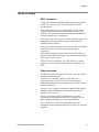
The EST3 library
EST3 documents
A library of documents and multi-media presentations supports
the EST3 life safety system. A brief description of each is
provided below.
EST3 Installation and Service Manual (P/N 270380): Gives
complete information on how to install and service the EST3
hardware. The manual also includes installation information on
selected Signature Series components.
SDU Online Help (P/N 180653): Provides full online support for
configuring and programming a system using the System
Definition Utility program.
EST3 System Operation Manual (P/N 270382): Provides detailed
information on how to operate the system and system
components.
EST3 Smoke Management Application Manual (P/N 270913):
Provides information for designing, programming, and testing an
EST3 smoke control system.
EST3 ULI ULC Compatibility Lists (P/N 3100427): Lists the
appliances, devices, and accessories that are compatible with
EST3.
Other documents
In addition to documents in the EST3 library, you may find the
following documents useful.
Signature Series Intelligent Smoke and Heat Detectors
Applications Bulletin (P/N 270145): Provides additional
applications information on the Signature series smoke and heat
detector applications.
Signature Series Component Installation Manual (P/N 270497):
Contains detailed mounting and wiring information for all
Signature series devices.
Speaker Application Guide (P/N 85000-0033): Provides
information on the placement and layout of speakers for fire
alarm signaling and emergency voice communications.
Strobe Applications Guide (P/N 85000-0049): Provides
information on the placement and layout of strobes for fire alarm
signaling.
EST3 Installation and Service Manual
xi
Content
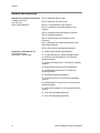
Related documentation
National Fire Protection Association
1 Batterymarch Park
P.O. Box 9101
Quincy, MA 02269-9101
NFPA 70 National Electric Code
NFPA 72 National Fire Alarm Code
NFPA 11 Low-Expansion Foam Systems
NFPA 11A Medium- and High-Expansion Foam
Systems
NFPA 12 Carbon Dioxide Extinguishing Systems
NFPA 13 Sprinkler Systems
NFPA 15 Water Spray Fixed Systems for Fire
Protection
NFPA 16 Deluge Foam-Water Sprinkler and FoamWater Spray Systems
NFPA 17Dry Chemical Extinguishing Systems
Underwriters Laboratories, Inc.
333 Pfingsten Road
Northbrook, IL 60062-2096
UL 38 Manually Actuated Signaling Boxes
UL 217 Smoke Detectors, Single & Multiple Station
UL 228 Door Closers/Holders for Fire Protective
Signaling Systems
UL 268 Smoke Detectors for Fire Protective Signaling
Systems
UL 268A Smoke Detectors for Duct Applications
UL 346 Waterflow Indicators for Fire Protective
Signaling Systems
UL 464 Audible Signaling Appliances
UL 521 Heat Detectors for Fire Protective Signaling
Systems
UL 864 Standard for Control Units for Fire Protective
Signaling Systems
UL 1481 Power Supplies for Fire Protective Signaling
Systems
UL 1638 Visual Signaling Appliances
UL 1971 Visual Signaling Appliances
xii
EST3 Installation and Service Manual
Content
Canadian Electrical Code Part 1
Underwriters Laboratories of
Canada
ULC S527 Standard for Control Units for Fire Alarm
Systems
7 Crouse Road
Scarborough, ON
Canada M1R 3A9
ULC S524 Standard for the Installation of Fire Alarm
Systems
ULC S536 Standard for the Inspection and Testing of
Fire Alarm Systems
ULC S537 Standard for the Verification of Fire Alarm
Systems
ULC ORD–C693–1994 Central Station Fire Protective
Signaling System and Services
CAN/ULC-S301 Standard for Central and Monitoring
Station Burglar Alarm Systems
CAN/ULC-S302 Standard for Installation and
Classification of Burglar Alarm Systems for Financial
and Commercial Premises, Safes, and Vaults
CAN/ULC-S303 Standard for Local Burglar Alarm Units
and Systems
CAN/ULC-S304 Standard for Central and Monitoring
Station Burglar Alarm Units
PLUS: Requirements of state and local building codes and the
local authority having jurisdiction.
EST3 Installation and Service Manual
xiii
Content
xiv
EST3 Installation and Service Manual
Chapter 1
System overview
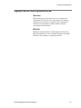
Summary
This chapter provides a descriptive overview of the components
and subsystems that comprise a system.
Content
System description • 1.2
System features • 1.3
Minimum system requirements • 1.4
System construction • 1.4
Audio subsystem description • 1.6
Network audio riser wiring • 1.6
Amplifiers • 1.7
Backup amplifiers • 1.8
3-ASU Audio Source Unit • 1.9
Firefighter phone • 1.15
Digital network subsystem • 1.16
Network data riser wiring • 1.16
Class B network data risers • 1.16
Class A network data risers • 1.17
Download connections • 1.18
Downloading database files over the network • 1.19
Foreign language support • 1.22
Printer use with foreign languages • 1.22
Bilingual language support • 1.22
Display device language support • 1.23
Signature series devices • 1.26
Network applications • 1.29
Network layout • 1.29
Feature/function domain • 1.30
Audio applications • 1.33
Audio channels • 1.34
Manual audio zone selection • 1.38
Messages • 1.39
Firefighter phone system • 1.42
Five phone off-hook limit • 1.42
One phone per circuit • 1.42
Five phones per circuit • 1.43
Limited number of portable telephone handsets • 1.43
EST3 Installation and Service Manual
1.1
System overview
System description
EST3 is designed using modular hardware and software
components to facilitate rapid configuration, installation, and
testing. Most network components are provided as local rail
modules (LRMs) that plug into the rail chassis assemblies. Rail
chassis assemblies are available to meet most any application.
Rail modules are used for data processing, intrapanel
communication of command/control data, response data, audio
signal processing, and power distribution. Each rail module
provides an interface to support a control/display module that
can be mounted on the front of the module. Most field wiring is
terminated using removable terminal strips for easy installation
and servicing of modules.
Cabinets are available in a variety of sizes. The smallest (3CAB5), in addition to the central processor module and primary
power supply module, supports two rail modules and three
control/display modules. The largest, the 3-CAB21 supports as
many as 18 rail modules and 19 control/display modules.
An EST3 cabinet can be configured as a stand-alone system or as
part of a network which supports up to 64 cabinets on a
peer-to-peer Class A or B token ring network. Below is a partial
list of local rail modules that can be incorporated into a system:
•
Central Processor module (CPU). One is required for each
panel. Several models of CPU are available. See the current
compatibility lists for details.
•
Primary Power Supply module (3 PPS/M, 3 BPS/M, or 3
BBC/M). One power supply module is required for each
panel.
•
Main LCD Display module (LCD). One LCD is required to
provide a point of control for the entire network. Additional
displays can be added to any CPU module for additional
points of control or annunciation. Several LCD models are
available. See the current compatibility lists for details.
Additional control/display modules as required by the
application:
•
•
•
•
•
•
•
•
1.2
3-BPS/M Booster Power Supply module
3-MODCOM Modem Communicator module
3-SAC Security Access Control module
3-SSDC(1) Signature Driver Controller module
3-AADC(1) Analog Addressable Driver Controller module
3-IDC8/4 Initiating Device Circuit module
3-OPS Off-Premises Signaling module
3-ZAxx Zoned Amplifier modules
EST3 Installation and Service Manual
System overview
The audio and firefighter phone functions use a different
hardware format, providing operator controls and storage for the
microphone and telephone handset in a chassis configuration.
System features
Each cabinet in the system provides local control, display, power
supply, and communication functions. Each cabinet has the
following capacities:
•
10 addressable device circuits (Signature and addressable
analog combined)
•
120 traditional input / output zones
•
4 Class B (2 Class A) security / access control
communication (SAC) busses
•
10 modem / dialer cards, each with two telephone lines
•
2 RS-232 external peripheral device ports
•
456 LED annunciation points
•
342 input switches
In addition, the EST3 system has these global features:
•
Firefighter telephone
•
Custom programmability and user-friendly front panel
•
Class B (Style B), initiating device circuits (IDC)
•
Event reporting by alarm, trouble, supervisory, or monitor
mode and message display routing
•
Dead front construction
•
Supports networking — up to 64 nodes may be connected in
a regenerative Class A or Class B token ring
•
Fast response time, less than three seconds from initial alarm
to device activation on a fully loaded system over the
network
•
Flash memory on controller modules to facilitate quick
firmware upgrades
•
Supports 255 security partitions
•
Multiplexed eight-channel digital audio system
•
Transient protected field wiring
•
Class B (Style Y) or Class A notification appliance circuits
•
Ground fault detection by panel, Signature data circuit, and
Signature modules
•
Switch mode power supply
EST3 Installation and Service Manual
1.3
System overview
•
Copper or fiber network and audio communications
•
Application and firmware downloading over the network or
from a single point
•
Network-wide control routing
•
Form C alarm, supervisory, and trouble relay contacts
Refer to the release notes for the latest information regarding
specifications and capabilities.
Minimum system requirements
NFPA 72 system
classification
Required control equipment
Protected Premises
(Local)
Cabinet with a CPU (Central Processor
module), one LCD (Main LCD Display
module) one 3-PPS/M Primary Power
Supply and Monitor, appropriate
batteries, plus appropriate initiating
device circuits and notification appliance
circuits
Auxiliary
—or—
Remote Station
—or—
Proprietary Protected
Premises
Add a 3-OPS Off Premises Signal
module or a correctly configured and
programmed 3-MODCOM Modem
Communicator module to the protected
premises system
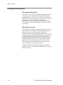
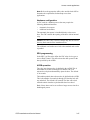
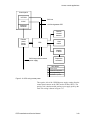
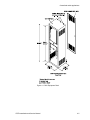
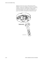
System construction
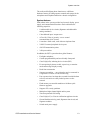
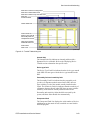
The EST3 system is assembled in layers as shown in Figure 1-1.
The cabinet (1) houses all the system components. A variety of
cabinets are available for as few as 5 and as many as 21 modules.
A 3-RCC14 cabinet is illustrated in Figure 1-1.
Mounted directly to the cabinets are the rail chassis assemblies
(2), of which there are three types: rail, audio, and audio with
telephone. The most common chassis is the rail chassis, which
provides mounting and electrical connections for the local rail
modules (LRMs) (4). Mounted on the rear of the chassis are the
cabinet power supplies (3).
The local rail modules (4) are the specialized cards that provide
an interface between the CPU and the field wiring. The front of
any rail module can support a control/display module (5),
providing customized operator controls and annunciators.
1.4
EST3 Installation and Service Manual
System overview
Completing the EST3 “CAB” series cabinet assembly are the
inner (6) and outer (7) doors. The “RCC” cabinets use a single
outer door.
Figure 1-1: Exploded CAB series cabinet equipment installation
EST3 Installation and Service Manual
1.5
System overview
Audio subsystem description
The audio subsystem consists of a variety of signal sources,
integral amplifiers, and sophisticated control software. The
3-ASU Audio Source Unit is available with the optional 3-FTCU
Firefighter Telephone Control Unit as the model 3-ASU/FT. The
ASU/FT is the only audio equipment required at the fire
command control center. Zoned audio amplifiers are distributed
throughout the system and provide the de-multiplexing,
switching, amplification and circuit supervision.
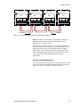
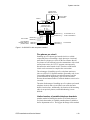
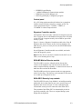
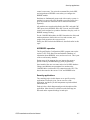
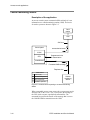
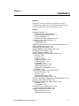
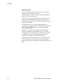
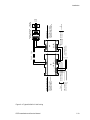
Network audio riser wiring
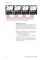
A digital network audio riser consisting of a single pair (Class B)
or two pairs (Class A) of wires connect all amplifiers together.
Since the digital signals are multiplexed, any of 8 independent
audio sources can be directed to any amplifier connected to the
network. All command and control signals for the audio system
are distributed over the network data riser.
CPU
CPU
CPU
CPU
TB2
TB2
TB2
TB2
AUDIO
A IN
AUDIO
A OUT
AUDIO AUDIO
B IN
B OUT
AUDIO
A IN
AUDIO AUDIO AUDIO
A OUT
B IN
B OUT
AUDIO
A IN
AUDIO
A OUT
AUDIO AUDIO
B IN
B OUT
AUDIO
A IN
AUDIO AUDIO AUDIO
A OUT
B IN
B OUT
From
AUDIO DATA PRIMARY
on 3-ASU
Figure 1-2: Class B network audio riser wiring
1.6
EST3 Installation and Service Manual
System overview
CPU
CPU
CPU
CPU
TB2
TB2
TB2
TB2
AUDIO
A IN
AUDIO AUDIO AUDIO
A OUT
B IN
B OUT
AUDIO
A IN
AUDIO AUDIO AUDIO
A OUT
B IN
B OUT
AUDIO
A IN
AUDIO
A OUT
AUDIO AUDIO
B IN
B OUT
AUDIO
A IN
AUDIO AUDIO AUDIO
A OUT
B IN
B OUT
From
AUDIO DATA PRIMARY
connections on 3-ASU
Figure 1-3: Class A network audio riser wiring
Amplifiers
Amplifiers are designed to feed a single audio zone and provide
an integral 24 Vdc visual notification appliance circuit.
Amplifier modules are available in 20-, 40-, and 95-watt
versions, with each amplifier providing a single supervised Class
B or A audio output circuit. The amplifier is configurable for
either 25 Vrms or 70 Vrms output. An independent supervised
Class B or Class A, 24 Vdc, 3.5 Amp notification appliance
circuit (NAC) is also provided on the 20- and 40-watt amplifiers
to drive notification appliances. In addition, automatic backup
amplifiers can be added on a switched common backup
configuration.
Each audio power amplifier has an integral demultiplexer,
making the 8 audio channels available to the amplifier’s input, as
directed by the system programming. Each amplifier also
contains circuitry that handles routine signal processing
functions such as channel priority.
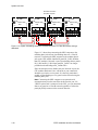
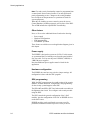
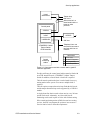
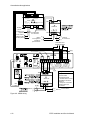
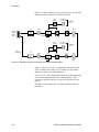
The amplifier’s output is a dedicated, supervised, 25-, 70-Vrms
speaker circuit, which covers one audio zone in the protected
facility. Figure 1-4 is an example of an enclosure with four zone
amplifiers and a backup amplifier. In response to an alarm,
selected audio amplifiers have been connected to the required
audio channels. Note that three different audio signals are being
broadcast simultaneously.
EST3 Installation and Service Manual
1.7
System overview
Network Data Riser
Network Audio Riser
Equipment Enclosure
Central
Processor
Module
Local Rail Bus
Backup
Amplifier
Zoned
Amplifier
Zoned
Amplifier
Page
Page
Zoned
Amplifier
Zoned
Amplifier
EVAC
Alert
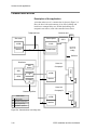
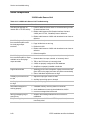
Figure 1-4: Normal amplifier operation
Possible fault condition
Amplifier operation
Amplifier loses communication If the panel is configured for stand-alone operation, the amplifier
with Central Processor module automatically switches to the EVAC channel and outputs its 1
kHz temporal tone when the panel detects an alarm.
If the panel is not configured for stand-alone operation, the
amplifier will not output any signal.
Panel loses communication
with network data riser
Amplifier switches to the EVAC channel only in response to the
local panel’s programming uses the default EVAC message.
Panel loses communication
with network audio riser
Amplifier switches to the EVAC channel in response to the
system programming. For EVAC the amplifier uses its 1 kHz
temporal tone. For Alert the amplifier uses its 1 kHz 20 bps tone.
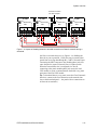
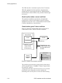
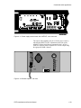
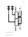
Backup amplifiers
In the event of an amplifier failure (not a field wiring problem),
the backup amplifier automatically replaces the failed amplifier,
as shown in Figure 1-5.
1.8
EST3 Installation and Service Manual
System overview
Network Data Riser
Network Audio Riser
Equipment Enclosure
Central
Processor
Module
Local Rail Bus
Backup
Amplifier
Zoned
Amplifier
Page
Zoned
Amplifier
Page
Zoned
Amplifier
EVAC
Zoned
Amplifier
Alert
Figure 1-5: Single amplifier failure
The amplifier failure caused the backup amplifier to
automatically connect to the same audio source as the failed
amplifier. The output of the backup amplifier replaced the output
of the failed amplifier.
Note: The
backup amplifier will not replace an amplifier that has
detected a field wiring problem to prevent the amplifier from
driving into a shorted circuit.
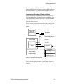
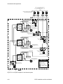
3-ASU Audio Source Unit
The 3-ASU is the source of the network audio riser. Available
audio sources are local and remote voice PAGE functions and
the firefighter telephone PAGE function. An integral tone
generator database is provided for the EVAC, ALERT and other
functions. Alternately, the 3-ASU’s integral digital voice
message playback unit can simultaneously provide up to 8
different prerecorded audio messages that may be assigned to
any channel.
The multiplexer within the 3-ASU converts and compresses the
real-time audio signal and converts it to a digital format. The
output of the digital message playback unit and the integral tone
generator database is already in the digital format. The 8 signal
sources in digital format are then combined together as selected
by the system designer using a multiplexer. This makes up the
network audio riser signal.
EST3 Installation and Service Manual
1.9
System overview
Local mic.
Remote mic.
Firefighter’s
telephone
Auxiliary
input
Multiplexer
Audio signals
Network audio riser (eight
digitized audio channels)
Digital message
playback unit
Tone / message
database
Digital signals
Figure 1-6: ASU Signal Flow
The amplifiers at the remote-panels extract the audio signals
from the network riser, amplify it and send it to the speakers.
25/70 VRMS
supervised audio
circuit
Local tone
generator
Network audio riser
(eight digitized audio
channels)
Demultiplex
and decode
Channel
selection and
supervision
Power
amp
Network data riser
(command and control)
EOLR
Figure 1-7: Amplifier Signal Flow
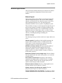
Audio signal priority
During system configuration, each of the eight available audio
channels is assigned one of the five available attributes listed in
Table 1-1. The Page, and Auxiliary attributes may only be
assigned to a single channel. The General attribute may be
assigned to up to four channels.
Table 1-1: Network audio channel parameters
1.10
Channel attribute
Priority
PAGE
1
EVAC
2
ALERT
3
AUXILIARY
4
EST3 Installation and Service Manual
System overview
Table 1-1: Network audio channel parameters
Channel attribute
Priority
GENERAL
5
Each channel attribute has a priority level associated with it.
When more than one channel is commanded to source a given
amplifier, the amplifier will connect to the source having the
highest priority. The Page channel will only go active when the
microphone push-to-talk switch is pressed.
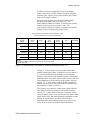
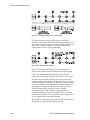
Special audio source unit page modes
The front panel of the ASU offers four special page mode
switches:
•
•
•
•
All Call
EVAC
Alert
All Call Minus
These switches provide instantaneous switching of the page
signal to the most frequently contacted areas of the building. The
special page modes do not require any source switching by the
zoned audio amplifiers. When a special page mode switch is
activated, the signal content of the eight outgoing audio channels
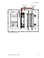
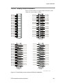
is modified. Figure 1-8 illustrates this principle.
In the normal page mode, the eight audio signal sources are each
connected to a separate audio channel, as represented by a at
the intersection of the signal source and the audio channel,
shown at the lower left of Figure 1-8. Each audio channel is
represented as a vertical line in this figure. The eight audio
channels are actually multiplexed together and distributed over a
common pair of wires called the network audio riser. The figure
shows the system in the normal page mode, with the zoned audio
amplifiers processing EVAC signals on the 1st and 3rd levels, a
page signal on the 2nd level, and the alert signal on the 4th level.
EST3 Installation and Service Manual
1.11
System overview
Eight multiplexed audio channels
on a two-wire circuit
25/70 VRMS supervised
audio circuit
Power
amp
EOLR
Local tone
generator
ALERT
25/70 VRMS supervised
audio circuit
Power
amp
EOLR
Network data riser
Local tone
generator
EVAC
25/70 VRMS supervised
audio circuit
Power
amp
EOLR
Local tone
generator
PAGE
25/70 VRMS supervised
audio circuit
Power
amp
EOLR
Local tone
generator
3-ASU signal sources
EVAC
Network audio signals
Page
Evac
Alert
Auxiliary
General1
General2
General3
General4
= Audio source unit
audio signal to audio
channel connection
Normal mode
Audio signal distribution during special paging modes
Page
Evac
Alert
Auxiliary
General1
General2
General3
General4
ALL CALL mode
Page
Evac
Alert
Auxiliary
General1
General2
General3
General4
Page to EVAC mode
Page
Evac
Alert
Auxiliary
General1
General2
General3
General4
Page
Evac
Alert
Auxiliary
General1
General2
General3
General4
Page to ALERT mode
ALL CALL MINUS mode
Figure 1-8: Audio Source Unit Special Page Mode Signal Flow
1.12
EST3 Installation and Service Manual
System overview
The All Call mode is used to send a page to the entire facility.
When the All Call switch is activated, the Audio Source Unit is
put into the all call mode. In this mode, the zoned audio
amplifiers do not all transfer to the page channel. Rather, the
Audio Source Unit redirects the page signal source to all the
audio channels. Figure 1-8 shows the all call page source to
audio channel connections in the lower left corner. Note that all
channels receive the same signal. Any amplifier on the system,
regardless of the audio channel selected, will receive the page.
Any amplifiers that were previously idle will power up and
receive the page.
The Page to EVAC mode is used to send a page to the areas
automatically receiving the evacuation signal. Activating the
EVAC switch causes the Audio Source Unit to enter the page to
EVAC mode. In this mode, the zoned audio amplifiers connected
to the EVAC channel do not transfer to the page channel. Rather,
the Audio Source Unit redirects the page signal source to the
EVAC channel. Figure 1-8 shows the page to EVAC mode page
source to EVAC channel connections. The page and EVAC
audio channels both receive the page signal. Any amplifier
connected to either the page or EVAC audio channels will
receive the page. The alert, auxiliary and general channels are
connected to their respective signal sources, as in the normal
mode.
The Page to Alert mode is used to send a page to the areas
automatically receiving the alert signal. Activating the Alert
switch causes the Audio Source Unit to enter the page to alert
mode. In this mode, the zoned audio amplifiers connected to the
alert channel do not transfer to the page channel. Rather, the
Audio Source Unit redirects the page signal source to the alert
channel. Figure 1-8 shows the page to alert mode page source to
alert channel connections. The page and alert audio channels
both receive the page signal. Any amplifier connected to either
the page or alert audio channels will receive the page. Any
amplifiers that were previously idle will power up and receive
the page. The EVAC, auxiliary and general channels are
connected to their respective signal sources, as in the normal
mode.
The All Call Minus mode is used to send a page to all areas NOT
automatically receiving the EVAC or alert signals. In high rise
applications, all call minus is an effective way to quickly select
stairwells. Activating the All Call Minus switch causes the
Audio Source Unit to enter the all call minus mode. In this mode,
the zoned audio amplifiers connected to the auxiliary and general
channels do not transfer to the page channel. Rather, the Audio
Source Unit redirects the page signal source to the auxiliary and
four general channels. Figure 1-8 shows the all call minus mode
page source to auxiliary and general channel connections. The
EST3 Installation and Service Manual
1.13
System overview
page, auxiliary and four general audio channels all receive the
page signal. Any amplifier connected to the page, auxiliary or
general audio channels will receive the page. The EVAC and
alert channels are connected to their respective signal sources, as
in the normal mode.
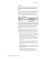
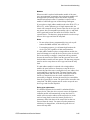
Automatic messaging
One of the features of the 3-ASU Audio Source Unit is the
method used to monitor the integrity of the digital audio system.
When an audio messaging system is configured, default audio
messages are recorded for the Evacuation and Alert channels.
The text of default messages should be generic in nature, and
should not include location-specific instructions. When the
system is in the normal condition, the 3-ASU continuously
transmits default messages over the network audio riser. The
zone amplifiers use the default messages to verify their
operational integrity, as well as the integrity of the riser wiring.
When an alarm is detected, the evacuation and alert message
channels are selected by the amplifiers in the appropriate areas in
the facility, as directed by the system rules. If a specific
evacuation message has been programmed to play in response to
the alarm, it is sent out over the evacuation channel. Location
specific evacuation messages contain information and
instructions that should only be used for a specific alarm
location. Should a second alarm from another location be
received, the evacuation message playing as a result of the first
alarm may not be appropriate for the second alarm.
Note: In the event of conflicting messaging instructions caused
by multiple alarm events, the system will play the default
evacuation message, whenever two or more different messages
are requested at the same time on the evacuation channel.
Automatic message processing is illustrated in Figure 1-9. By
reverting back to the generic default evacuation message in
multiple alarm location scenarios, no one can be misdirected by
the wrong message. Default messages also play during alarms
when no location specific message has been requested.
1.14
EST3 Installation and Service Manual
System overview
83
82
80th floor, west wing evacuation message:
A fire has been reported on the west wing
of the 80th floor.
81
80
79
78
77
Generic (default) message:
An emergency has been reported in the
building. Remain where you are and await
further instructions.
Location specific messages
33
32
30th floor, north wing evacuation message:
A fire has been reported on the north wing
of the 30th floor.
31
30
29
Generic (default) evacuation message
28
The generic (default) evacuation
message plays when multiple locationspecific messages have been requested
by the system, or when no locationspecific message has been specified.
27
Figure 1-9: Automatic Message Processing
Firefighter phone
The 3-FTCU contains a master telephone handset that provides
an analog telephone riser for totally independent 2-way
communications between the fire command station and
Firefighter telephone stations / jack telephones installed at
strategic locations throughout the protected facility.
Taking a telephone off-hook or plugging into a telephone jack
generates a visual and audible incoming call signal at the fire
command station. The individual originating the call hears a tone
until the handset is connected to the system. The fire command
station operator manually connects the incoming phone call to
the phone riser to complete the call. Up to five remote telephones
may be connected to the riser simultaneously. The fire command
center operator can also use the telephone circuit as a page
source, permitting paging via the telephone system.
EST3 Installation and Service Manual
1.15
System overview
Digital network subsystem
Network data riser wiring
The network data riser provides the communication path
between each CPU module (3-CPUx or 3-ANNCPUx) installed
in the system. Each CPU module has two bi-directional RS-485
ports (Network A and Network B) that are used to connect the
network data riser wiring. Network B is isolated from ground
and Network A is not.
The correct method for running the network data riser is to
connect the isolated Network B port on one CPU module to the
non-isolated Network A port on another. Any remote CPU
modules connected to a local CPU module’s Network B port is
considered to be downstream from the local CPU module. Any
remote CPU modules connected to a local CPU module’s
Network A port is considered upstream from the local CPU
module.
Additionally, next and previous refer to the order in which
remote CPU modules are electrically connected to a local CPU
module. Previous refers to the remote CPU module whose
isolated Network B port connects to the local CPU module’s
non-isolated Network A port. Next refers to the remote CPU
module whose non-isolated Network A port connects to the local
CPU module’s isolated Network B port.
Note: Since the data traveling the network data riser is
bi-directional, out and in references are used to direct wire
connections.
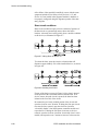
Class B network data risers
In a Class B network, a break or short in the network data riser
wiring divides the network into separate independent networks.
Panels on the same side of the line fault will communicate with
each other but not with panels across the line fault. Figure 1-10
shows the wiring for a Class B network.
1.16
EST3 Installation and Service Manual
System overview
B1_CAB1
J5
B1_CAB2
J5
CPU
TB2
J5
CPU
TB2
NETWORK
OUT
IN
A
B
A
B
AUDIO
A IN
B1_CAB3
J5
CPU
TB2
NETWORK
OUT
IN
A
B
A
B
AUDIO
A IN
NETWORK
OUT
IN
A
B
A
B
B1_CAB4
CPU
TB2
AUDIO
A IN
NETWORK
OUT
IN
A
B
A
B
AUDIO
A IN
Upstream
Downstream
Figure 1-10: Class B network data riser wiring using copper wire
Note: As a matter of convention, a Class B network data riser
should start at the CPU module that does not have wires
connected to its Network A port.
When wiring a Class B network, give careful consideration as to
the location of the service panel. The service panel provides a
single point from which you can download files to all other
panels on the network. For this function to work properly you
must use the panel at the start of the network data riser as the
service panel. See “Downloading data files” for more
information.
Class A network data risers
In a Class A network, a single break or short in the network data
riser wiring does not interrupt communications between panels.
Figure 1-11 shows the wiring for a Class A network.
EST3 Installation and Service Manual
1.17
System overview
B1_CAB1
J5
J5
CPU
TB2
NETWORK
OUT
IN
A
A
B
B
B1_CAB2
J5
CPU
TB2
AUDIO
A IN
B1_CAB3
J5
CPU
TB2
NETWORK
OUT
IN
A
A
B
B
AUDIO
A IN
B1_CAB4
CPU
TB2
NETWORK
OUT
IN
A
A
B
B
AUDIO
A IN
NETWORK
OUT
IN
A
A
B
B
AUDIO
A IN
Figure 1-11: Typical Class A network data riser wiring using copper wire
Download connections
Each programmable rail module has a modular phone jack to use
for downloading data directly from the SDU computer. The
modular phone jack on any CPU module can also be used to
download data to other programmable rail modules in the same
panel over the rail bus, or to other panels over the network data
riser.
In addition to the modular phone jack, the CPU module has two
serial communication ports that can be used to download data,
provided both of these conditions are met:
•
•
A 3-RS232 option card is installed
The serial port used to download data is not configured for
gateway or coder applications
Tip: To download data over the network without having to
reconfigure the system, temporarily install a 3-RS232 option
card on any CPU module in the system and connect the SDU
computer to serial port 1.
1.18
EST3 Installation and Service Manual
System overview
Connect here to download data to all three programmable
rail modules over the rail bus (network mode) or to this
programmable rail module only (single-step mode)
N
O
C
N
C
N
O
TR OU BLE
C
N
A
N
C
C
N
O
A LA R M
N
C
B
+
B
-
S
H
A
+
A
-
SI GA 1
SI GA 1
S UP
SP
MW
KR
1
B
+
B
-
B
+
SI GA 1
B
-
S
H
A
+
A SP
- MW
KR
1
SI GA 1
SI GA 1
B
+
B
-
SI GA 1
TB1
J9
J8
J11
J10
OUT PU T M OD U LE
OUT PU T M OD U LE
J1
A
+
N ETW O RK
OU T
IN
A B
B
+
-
A UD I O
A IN
+
-
A UD I O
A OU T
+
-
A UD I O
B IN
+
-
A UD I O
B OU T
+
-
R
X
1
T
X
1
R
T
S
1
C
O R
M X
1 2
T
X
2
R
T
S
2
C
O
M
2
SI GA 2
B
-
B
+
2
SP
MW
KR
SI GA 2
A
-
Optional serial ports may be used to
download over the network (3RS232 required)
A
+
SI GA 2
S
H
B
-
B
+
SI GA 2
B
-
B
+
2
SP
MW
KR
SI GA 2
A
-
A
+
SI GA 2
S
H
B
-
B
+
Connect here to download data to
this programmable rail module only
(single-step mode)
Figure 1-12: Potential connection points for downloading data
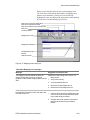
Downloading database files over the network
A CPU module’s Network A port and its modular phone jack
share an interrupt with the module’s microprocessor. As such,
the microprocessor disables the Network A port whenever you
connect the SDU computer to the modular phone jack.
Consequently, download options differ for Class A and Class B
networks.
EST3 Installation and Service Manual
1.19
System overview
Download connection
from SDU computer
B1_CAB1
J5
J5
CPU
TB2
NETWORK
OUT
IN
A
B
A
B
B1_CAB2
J5
CPU
TB2
AUDIO
A IN
B1_CAB3
J5
CPU
TB2
NETWORK
OUT
IN
A
B
A
B
AUDIO
A IN
B1_CAB4
CPU
TB2
NETWORK
OUT
IN
A
B
A
B
AUDIO
A IN
NETWORK
OUT
IN
A
B
A
B
AUDIO
A IN
Figure 1-13: Impact of disabling Network A terminal connection on Class B networks during a
download
Figure 1-13 shows how connecting the SDU computer to the
modular phone jack affects downloading data over a Class B
network. Connecting the SDU computer to the modular phone
jack on the CPU module installed in panel B1_CAB3, disables
that CPU module’s Network A port. Downloading data to panels
B1_CAB2 and B1_CAB1 from panel B1_CAB3 is no longer
possible but downloading to B1_CAB4 still is.
Since the microprocessor disables only the Network A port, the
CPU module that doesn’t have a Network A port connection
should be used as the service panel. It is the only panel that is
capable of downloading to every panel on the network using the
modular phone jack.
Note: Connecting the SDU computer to an optional serial
communications port does not affect the Network A port. If a
3-RS232 option card is connected to the CPU, you can download
data to any panel on a Class B network regardless of where the
panel physically connects to the network data riser.
1.20
EST3 Installation and Service Manual
System overview
Download connection
from SDU computer
B1_CAB1
J5
J5
CPU
TB2
NETWORK
OUT
IN
A
B
A
B
B1_CAB2
J5
CPU
TB2
AUDIO
A IN
B1_CAB3
J5
CPU
TB2
NETWORK
OUT
IN
A
B
A
B
AUDIO
A IN
NETWORK
OUT
IN
A
B
A
B
B1_CAB4
CPU
TB2
AUDIO
A IN
NETWORK
OUT
IN
A
B
A
B
AUDIO
A IN
Figure 1-14: Impact of disabling Network A terminal connection on Class A networks during a
download
On Class A networks however, see Figure 1-14, disabling the
Network A port on panel B1_CAB3 does not prevent the other
panels from receiving data through B1_CAB3’s Network B port.
Connecting the SDU computer to the modular phone jack does
cause the panel to report a Network Class A Failure trouble.
When the network data riser is configured for Class B,
connecting to the panel modular phone jack causes the local
CPU module to report a communications fault with every panel
upstream of the local CPU module.
Tip: To download data to every panel across the Class B network
data riser, connect to the first connection on the network data
riser as the download panel — the panel with no connections on
its Network A terminals.)
EST3 Installation and Service Manual
1.21
System overview
Foreign language support
Printer use with foreign languages
When supporting a single-byte character set language, your
printer must be able to support the appropriate DOS code page.
To support a double-byte character set language, your printer
must be able to support the appropriate Windows code page. The
required code pages are listed below.
Remember that not all Windows characters are available on DOS
printers, so some characters are not supported on these printers.
Language
Code page
Chinese simplified
Windows Page Code 936 (GB)
Chinese traditional
Windows Code Page 950
(Big 5)
Korean
Windows Code Page 949
(Extended Wansung)
Hebrew
DOS Code Page 862
Turkish
DOS Code Page 857
Dutch, French, Italian,
Portuguese, Spanish, English
DOS Code Page 850
Polish, Slovak
DOS Code Page 852
Russian
DOS Code Page 866
Bilingual language support
EST3 display modules (all LCD models and the KPDISP)
feature bilingual operation. For two languages to be supported
simultaneously, they must appear on the same code page. Refer
to the table below to determine the system bilingual capabilities.
Bilingual operation is not supported for Chinese and Korean.
1.22
Windows code page
Languages supported
1250 (Eastern Europe)
English, Polish Slovak
1251 (Cyrillic)
English, Russian
1252 (Western Europe)
Dutch, English, French, Italian,
Portuguese, Spanish
1254 (Turkish)
English, Turkish
1255 (Hebrew)
English, Hebrew
EST3 Installation and Service Manual
System overview
Example: Bilingual operation between Polish and Slovak is
supported (code page 1250). Bilingual operation between Polish
and Russian is not supported, as no code page has both.
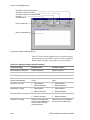
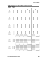
Display device language support
LCD language support
X
Chinese, simplified (PRC)
X
Dutch
X
English (UK)
X
X
X[1]
Mideast
Chinese, traditional (Taiwan)
Canadian
Asian
European
Language
US
Marketplace
X
X
English (US)
X
French Canadian
X
X
Hebrew
X
X
Italian
X
X
Korean, Extended Wansung
X
X
X
Polish
X
Portuguese (Brazil)
X
Russian
X
Slovak
X
X
X
X
Spanish (South America)
X
X
Turkish
X
X
[1] For testing and support purposes only
3-FTCU language support
Chinese, traditional (Taiwan)
[1]
Chinese, simplified (PRC)
[1]
EST3 Installation and Service Manual
Mideast
Canadian
Asian
European
Language
US
Marketplace
1.23
System overview
3-FTCU language support
English (UK)
X
X
Mideast
X
Canadian
Dutch
Asian
Language
European
US
Marketplace
X
X
X
English (US)
X
French Canadian
X
X
Hebrew
X
[1]
Italian
X
X
Korean, Extended Wansung
[1]
X
[1]
Portuguese (Brazil)
X
X
Spanish (South America)
X
X
Turkish
[1]
[1]
Russian
[1]
[1]
Polish
[1]
Slovak
[1]
[1]
[1] Only Western European character set is supported
KPDISP language support
Canadian
Mideast
Asian
Language
European
US
Marketplace
X
X
Chinese, traditional (Taiwan)
Chinese, simplified (PRC)
Dutch
X
English (UK)
X
English (US)
X
X
French Canadian
X
X
Hebrew
X
X
Italian
X
X
X
X
Korean, Extended Wansung
1.24
EST3 Installation and Service Manual
System overview
KPDISP language support
Polish
Mideast
Canadian
Asian
X
Portuguese (Brazil)
X
Russian
X
Slovak
X
X
X
X
Spanish (South America)
X
Turkish
X
EST3 Installation and Service Manual
European
Language
US
Marketplace
X
X
X
1.25
System overview
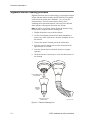
Signature series devices
The Signature series family consists of intelligent smoke and
heat detectors, bases, input/output modules, and ancillary
devices. The EST3 network supports Signature series devices
using several models of the Signature Driver Controller module.
Up to 125 detectors and 125 modules can be connected to the
Signature Data Circuit on these modules.
The Signature series smoke and heat detectors contain their own
microprocessors. This allows the devices to make alarm
decisions based on the information gathered by the sensing
elements incorporated in the device. Signature series detectors
can be installed in any of four detector bases:
• The Standard Base provides wiring terminals for connection
to a remote LED.
• The Relay Base provides a detector activated, pilot-duty dry
contact relay used to control external appliances.
• The Sounder Base incorporates a sounder horn that can be
controlled by the detector, by a special Signature module, by
the control panel, or by programmed rules
• The Isolator Base protects the Signature Data Circuit from
wiring shorts.
Signature modules interface and support the operation of
initiating devices, conventional 2-wire smoke and heat detectors,
manual pull-stations, strobes, bells, etc. The actual functions of
each Signature module is determined by a personality code
downloaded to the module through the System Definition Utility
(SDU) program.
Signature series manual pull-stations (1-stage and 2-stage)
feature an integral Signature module that monitors the station.
One-stage stations are monitored by a single input module that
sends an alarm signal to the loop controller when the station is
activated. Two-stage stations are monitored by a dual input
module which sends two independent alarm events to the control
panel; one when the pull-switch is activated, and the second
when the key switch is activated.
Alarm sensitivity setting
Alarm sensitivity refers to the primary threshold (expressed in
percent smoke obscuration) at which the smoke detector will go
into alarm. The alarm sensitivity setting for smoke detectors can
be set to one of five sensitivity levels. When smoke detectors
having both ionization and photoelectric elements are used, the
sensitivity setting applies to both elements. Reduced sensitivity
settings are used to reduce the occurrence of nuisance alarms.
1.26
EST3 Installation and Service Manual
System overview
The alarm sensitivity setting may be individually set for each
detector using the SDU program.
Alternate alarm sensitivity setting
Alternate alarm sensitivity refers to the secondary threshold
(expressed in percent smoke obscuration) at which the smoke
detector goes into alarm. The alternate alarm sensitivity setting
for smoke detectors can be set to one of the same five sensitivity
levels as the primary alarm. When smoke detectors having both
ionization and photoelectric elements are used, the sensitivity
setting applies to both elements. This feature permits increasing
or reducing an individual detector’s sensitivity at various times
of the day, dependent upon, environmental conditions,
occupancy, manufacturing processes, etc. Increased sensitivity is
typically used when a facility is unoccupied. Reduced sensitivity
is typically used to reduce the occurrence of nuisance alarms
when occupancy or environmental conditions may create
prealarm conditions. An alternate alarm sensitivity setting for
each detector can be set using the SDU program.
Alarm verification
Upon receipt of the initial alarm signal from a verified detector,
the EST3 panel issues a detector reset command. After a
programmable reset/retard period, if the detector continues to
generate an alarm during the fixed confirmation period, the
alarm is considered valid and processed by the EST3 control
panel. Alarm verification reduces the occurrence of nuisance
alarms, as it provides a time frame in which the cause of the
alarm can be investigated to determine whether an actual alarm
condition exists. The alarm verification period can be increased
or decreased through the SDU program, as limited by the listing
agencies.
Alternate alarm verification
The alternate alarm verification feature operates the same way
the alarm verification feature operates using a second, alternate,
programmed reset/retard period.
Prealarm setting
Signature smoke detectors can be configured to enter a prealarm
state, which generates a monitor event message. Detectors
configured for prealarm have a prealarm pseudo point for which
rules can be written.
During configuration, you specify a percentage of the alarm
sensitivity setting that will generate a prealarm event.
EST3 Installation and Service Manual
1.27
System overview
Alternate prealarm setting
The alternate prealarm setting is similar to the prealarm setting,
but it represents a percentage of the alternate alarm sensitivity
that will generate a prealarm event.
1.28
EST3 Installation and Service Manual
System overview
Network applications
This section deals with the initial layout of the network cabinets
as well as application configurations for the basic network
modules.
Network layout
The first task for the system designer is locating the equipment
cabinets throughout the project. The objective when locating
cabinets is to maximize the per cabinet coverage of the facility
while minimizing hardware cost. The following general
information should be used as a guide to designing the system.
The per cabinet coverage is, in some part, based upon the type of
project being designed. In a high rise building installation that
requires an audio emergency voice communication system, the
problem becomes how many floors can be served by a single
cabinet. In a campus style installation, there may be one or more
cabinets per building, depending on building size.
Cabinet coverage
The following factors govern how much area a single cabinet can
cover:
Cabinet capacity: Depending on the installed equipment, the
largest backbox available can have 21 module spaces and 3
chassis spaces. Is this enough cabinet capacity to house the
equipment required to cover the proposed area?
Available current per cabinet: Does the proposed number of
large current components (audio amplifiers and 24 Vdc
notification appliance circuits), in addition to the required
module currents, exceed the available 28 amps per cabinet or
60-Ah battery capacity?
Notification Appliance Circuit voltage drop: Does the distance
from the cabinet to the last strobe, horn, speaker, etc. exceed the
acceptable limits?
User interface requirements: Depending on the installed
equipment, the largest backbox available can have 19 module
displays installed. Will this provide enough capacity for the
required control/display module functions?
Distance between cabinets: Does the wiring length between
any three cabinets exceed 5,000 ft. (1,524 m)?
System capacity of 64 cabinets per network: Does the
proposed system require more than 64 cabinets?
Cost of installation labor and materials: Is it cheaper to install
a smaller cabinet and service the floor above and below the floor
EST3 Installation and Service Manual
1.29
System overview
of installation, or install a larger cabinet with more equipment,
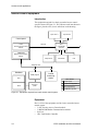
and wire two floors above and two floors below the cabinet
floor?
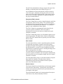
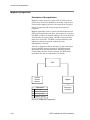
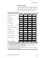
Feature/function domain
The EST3 life safety system utilizes peer-to-peer networking
technology. No single cabinet is in control of the network.
Peer-to-peer networking permits multiple control locations
within a single network. The feature/function domain is defined
as the group of cabinets that are affected when the feature or
function is activated. A network cabinet may be a part of one or
more groups. Multiple control locations are permitted for any
group.
Three types of domains are available.
Local: The feature/function affects only the cabinet on which the
LCD module is installed.
Group: The feature/function affects a predefined group of
cabinets on the network.
Global: The feature/function affects all the cabinets on the
network.
Group #3
Group #1
1
2
Group #2
3
4
5
6
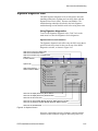
Figure 1-15: Sample domain consisting of three groups
Using the System Definition Utility (SDU), you can configure
the system so that information from any cabinet can be
selectively sent to any combination of other cabinets on the
network.
Each cabinet may selectively transmit the following information
to other cabinets on the network:
•
•
•
•
•
1.30
Reset commands
Alarm Silence commands
Trouble Silence commands
Drill commands
Acknowledge commands
EST3 Installation and Service Manual
System overview
A cabinet can also be configured to receive state changes
(Alarm, Supervisory, Trouble, Monitor, firefighter telephone
incoming calls), logicals, events, audio controls, and so forth,
from a select group of cabinets.
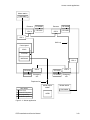
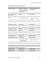
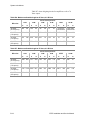
Feature/function domains are associated with the cabinet
providing the operator controls. In Figure 1-15, the
feature/function domain for Cabinet 1, which has the operator
controls for the first subnet, is groups 1 and 3. The
feature/function domain for Cabinet 6, which has the operator
controls for the second subnet is groups 2 and 3.
Two subnetworks, with operator controls at cabinets 1 and 6.
Cabinets 3 and 4 are common to both subnetworks.
Commands
Alarm
silence
Trouble
silence
1, 2, 3, 4
1, 2, 3, 4
1, 2, 3, 4
1, 2, 3, 4, 5, 6
1, 2, 3, 4
1, 2, 3, 4
N/A
N/A
N/A
N/A
N/A
Cabinet 3
1, 2, 3, 4, 5, 6
N/A
N/A
N/A
N/A
N/A
Cabinet 4
1, 2, 3, 4, 5, 6
N/A
N/A
N/A
N/A
N/A
Cabinet 5
3, 4, 5, 6
N/A
N/A
N/A
N/A
N/A
Cabinet 6
3, 4, 5, 6
3, 4, 5, 6
3, 4, 5, 6
3, 4, 5, 6
1, 2, 3, 4, 5, 6
3, 4, 5, 6
Group 2 Group 3 Group 1
Sending
cabinet
Cabinet
state
Reset
Cabinet 1
1, 2, 3, 4
Cabinet 2
Drill
Acknowledge
Legend
1 through 6 = Cabinets that receive commands from the sending cabinet
N/A = Not applicable
Figure 1-16: Routed network commands for the domain illustrated in Figure 1-15
In Figure 1-16, the Cabinet 1 entry under the Cabinet State
column indicates that Cabinet 1 should receive from cabinets 1,
2, 3, and 4 all information about changes of state. Because
Cabinet 1 is the location of the operator controls it should send
information about reset, alarm silence, trouble silence, drill, and
acknowledgments to all the cabinets in the domain, which are
cabinets 1, 2, 3, and 4. In this example, the drill command is
common to both systems. Note, that the drill command is also
sent to cabinets 5 and 6 by Cabinet 1.
The Cabinet 2 entry under the Cabinet State column indicates
that Cabinet 2 receives its change of state information from
cabinets 1, 2, 3, and 4. Because there are no operator controls
located at cabinet 2, there is no need to send reset, alarm silence,
trouble silence, drill, and acknowledgment information to other
cabinets. As an alternative, the table could show these
commands sent to other cabinets, because they can never be
issued due to the lack of an LCD module in the cabinet.
EST3 Installation and Service Manual
1.31
System overview
Cabinets 3 and 4 receive their change of state information from
all cabinets on the network, as indicated in the cabinet state
column. This is necessary as cabinets 3 and 4 are part of both
domains. Again, there is no need to send reset, alarm silence,
trouble silence, drill, and acknowledgment information to other
cabinets from cabinets 3 and 4.
The Cabinet 5 entry under the Cabinet State column indicates
that Cabinet 5 receives its change of state information from
cabinets 3, 4, 5, and 6.
Cabinet 6 information indicates that Cabinet 6 should receive
from cabinets 3, 4, 5, and 6 all information about changes of
state. Because cabinet 6 is the location of the operator controls it
should send information about reset, alarm silence, trouble
silence, drill, and acknowledgments to cabinets 3, 4, 5, and 6,
(all the cabinets in the domain.) In this example, the drill
command is common to both systems. Note, that the drill
command is also sent to cabinets 1 and 2 by Cabinet 6.
1.32
EST3 Installation and Service Manual
System overview
Audio applications
Amplifier selection
The EST3 system provides amplifiers with 20-, 40-, and 95-watt
output ratings to meet any project requirement. Selection of the
proper amplifiers requires an understanding of the amplifier
characteristics and application related information that follows.
Audio zoning
The output of each amplifier usually covers a single audio zone,
typically a floor of a high rise building. Using the appropriate
Signature modules, the amplifier’s output can be divided into
several zones. The output circuit can be configured for either
Class A or Class B wiring.
Output wattage
The output rating of an amplifier is determined by the speaker
load it is required to drive, and any expansion or safety factor
required. The speaker load is determined by adding up the value
of all the wattage taps selected on each speaker connected to the
amplifier. For a conservative approach, use the highest wattage
tap available on each speaker. This insures there is enough head
room to adjust speaker taps to compensate for any installation
variables such as sound absorbing furniture, etc.
Output voltage
Zoned amplifiers are available with either a 25 Vrms or 70 Vrms
output. The 25 Vrms output amplifiers are primarily used in
retrofit applications that previously had 25 Vrms speakers
installed. 70 Vrms output amplifiers are recommended for new
installations. The output circuits of a 70 Vrms amplifier can be
run eight-times farther than a 25 Vrms amplifier, given the same
load.
Note: If all the system wiring is required to be power limited,
you may use any 20-, 40-, or 95-watt amplifier with either a 25
Vrms or 70 Vrms output.
Wiring considerations
Refer to Appendix B of this manual for wire distance
calculations and other wiring considerations.
EST3 Installation and Service Manual
1.33
System overview
Backup amplifiers
Each cabinet can contain 1 zoned amplifier module to use to
back up the remaining primary zoned amplifier modules installed
in the same cabinet with the following restrictions:
•
All the amplifiers must have the same output voltage rating.
•
If the cabinet contains older amplifier modules (15- and
30-watt) and newer amplifier modules (20- and 40-watt), the
amplifier used to back up the primary amplifier modules
must be of the older type.
Note: In cases where older and newer zoned amplifiers exist in
the same cabinet, the older modules should be replaced with
newer modules for optimum results.
•
The backup amplifier must have an output wattage rating
equal to or greater than the largest primary amplifier it is
backing up. If not, the output capacity of the speaker circuit
is diminished proportionately.
•
The wire used to wire the backup amplifier to the other
amplifiers must be the same size or greater than that used to
wire the speaker circuit.
Cabinet space
The 20- and 40-watt amplifiers each require one space on the rail
assembly. The 95-watt amplifier requires two rail spaces.
The number of zoned amplifier modules that can be installed in a
single cabinet is limited by the number of available rail spaces,
the number of power supplies installed in the cabinet, and battery
limits, if any.
Audio channels
The EST3 audio system provides eight (8) simultaneous
channels for distribution of audio signals. The functions of four
of these channels are fixed by the system. These four channels
are referred to by their functions: Page, EVAC, Alert, and
Auxiliary Input channels. The four remaining channels are
referred to as general channels 1 to 4.
Under manual or automatic network control, each amplifier’s
input can be connected to either the Alert channel, the
Evacuation (EVAC) channel, the Page channel, the Auxiliary
Input channel, or one of four (4) general input channels. Should
conflicting commands be issued to a single amplifier, the
amplifier responds to the channel with the highest priority. The
eight channels are prioritized as follows, with the Page channel
having the highest priority
1.34
EST3 Installation and Service Manual
System overview
Page channel
Paging is a manual function. An operator is required to select a
destination for the page, and then make an announcement. The
Page channel is never automatically selected by the EST3
system.
The page channel always carries a live page signal, regardless of
its source. There are three sources which can supply the paging
signal: 1) the local 3-ASU microphone, 2) the remote
microphone, and the 3) the firefighter telephone system. These
sources are automatically prioritized as shown in Table 1-2.
Table 1-2: Page priorities
Priority
Page signal source
1 (highest)
Local microphone
2
Firefighter phone
3 (lowest)
Remote microphone
The page command is a non-latching function. When the page
command ends, amplifiers automatically switch back to the
source channel that was active (if any) prior to the page
command.
Five types of page commands are available on the network. The
first four page commands are available simply by pressing a
single switch on the front of the 3-ASU. These are the paging
functions most commonly used in an emergency situation.
1. The All Call command temporarily transfers all amplifiers to
the Page channel while the page is active. All Call distributes
the page signal to every amplifier in the system.
2. The Page to EVAC command temporarily transfers the Page
signal to all amplifiers actively connected to the EVAC
channel. All “EVAC” amplifiers then receive and distribute
the Page signal.
3. The Page to Alert command temporarily transfers the Page
signal to all amplifiers actively connected to the Alert
channel. All Alert amplifiers then receive and distribute the
page signal.
4. The All Call Minus command temporarily transfers the page
signal to all amplifiers except those connected to the EVAC
and Alert channels.
5. A Selective Page temporarily transfers the selected
amplifiers to the Page channel while the page is activate,
distributing the page signal only to selected audio zones
EST3 Installation and Service Manual
1.35
System overview
(amplifiers). Audio zones are selected manually by the
operator using the LED/Switch displays.
An example of how the page commands work is illustrated in
Figure 1-17. This figure shows a nine story high rise building,
with a fire on the 6th floor. The fire plan requires the evacuation
signal to be sounded on the fire floor, floor above the fire, and
floor below the fire. The alert signal is required to sounded in all
other areas of the building except the stairwells. The first column
(Fire Alarm) shows the automatic responses on the affected
floors according to the fire plan.
Floor
Fire
Alarm
ASU page commands
Page to
Alert
Page to
Evac
Stairwells
All Call
Minus
All Call
Page
Page
Zoned
Paging
9th floor
Alert
Alert
Page
Alert
Page
Alert
8th floor
Alert
Alert
Page
Alert
Page
Alert
7th floor
Evac
Page
Evac
Evac
Page
Evac
6th floor
Evac
Page
Evac
Evac
Page
Page
5th floor
Evac
Page
Evac
Evac
Page
Evac
4th floor
Alert
Alert
Page
Alert
Page
Alert
3rd floor
Alert
Alert
Page
Alert
Page
Alert
2nd floor
Alert
Alert
Page
Alert
Page
Alert
1st floor
Alert
Alert
Page
Alert
Page
Alert
Legend
Fire floor
Floor above or floor below fire
Figure 1-17: ASU Page Command Example
The Page to EVAC command replaces the EVAC signal with the
Page signal, as shown in the figure’s second column.
The third column shows the Page to Alert command response, all
the Alert signals have been replaced by the Page signal.
The All Call Minus command directs the Page to the areas which
are not receiving the EVAC or Alert signals, i.e. the stairwells.
In the fourth column of Figure 1-17, the stairwells receive the
Page signal when the All Call Minus command is used and do
not automatically receive either the EVAC or Alert signals.
1.36
EST3 Installation and Service Manual
System overview
The All Call command directs the page signal to all areas of the
building, as illustrated in the last column of Figure 1-17.
Any combination of floors and stairwells could be selected to
receive the page by manually selecting the audio zones on the
audio zone select control/display module. Notice that at no time
does any area receiving a signal have its signal interrupted by
any page command function.
Evacuation (EVAC) channel
The EVAC channel always carries a signal designed to notify the
occupants they must leave the facility. The evacuation signal
may take the form of a textual message, a variety of audio tones,
or an audio tone modulated by the standard 3-3-3 evacuation
pattern, or any combination of these signals.
The EVAC channel is preprogrammed, and activated by the
system in response to an alarm. The EVAC signal is
automatically sent to the areas that are in danger and require
immediate evacuation.
The EVAC channel has priority over all channels signals except
for the Page channel. The alarm silence function automatically
silences the EVAC channel when an operator presses the Alarm
Silence switch.
Alert channel
The Alert channel always carries a signal designed to notify the
occupants that an emergency situation exists in the facility.
Occupants hearing the alert signal are not in immediate danger,
but should prepare to evacuate. In some installations, the alert
signal advises occupants that persons evacuating the danger area
will be entering the area for safety.
The Alert channel is preprogrammed, and activated by the
system in response to an alarm. The Alert signal is automatically
sent to areas that are not in immediate danger and do not require
immediate evacuation.
The Alert channel has priority over all other channels except the
Page and EVAC channels. The alarm silence function
automatically silences the Alert channel when an operator
presses the Alarm Silence switch.
General channel
The General channel is used to distribute special purpose signals
to special areas in the facility. Typically these areas include
elevator cabs, stairwells, and areas in less peril than those areas
receiving the Alert signal.
The general channel signals can be preprogrammed in response
to an alarm, or they may be manually activated.
EST3 Installation and Service Manual
1.37
System overview
General channels have a lower priority than the Alert channel.
The alarm silence function does not automatically silence the
Alert channel unless programmed to do so.
Manual audio zone selection
If manual audio zone selection is required on the system, the
appropriate control/display modules must be mounted on
modules in the same cabinet as the Audio Source Unit. Typical
configurations of control/display modules is shown in Figure
1-18. Exact operation of each display is dependent on system
programming. Typical operation is described below.
A
Page
8th Fl
Page
8th Fl
Alert
Page
7th Fl
Page
7th Fl
Page
Page
6th Fl
Page
6th Fl
Alert
Page
5th Fl
Page
5th Fl
Page
Page
4th Fl
Page
4th Fl
Alert
Page
3rd Fl
Page
3rd Fl
Page
Page
2nd Fl
Page
2nd Fl
Alert
Page
1st Fl
Page
1st Fl
Page
B
Evac
Evac
Evac
Evac
C
Status
Status
Status
Status
Page
Alert
Page
Alert
Page
Alert
Page
Alert
Page
6th Floor
Page
Alert
5th Floor
Page
9th Fl
Status
4th Floor
Page
9th Fl
Evac
3rd Floor
Alert
2nd Floor
Page
10th Fl
Page
1st Floor
Page
10th Fl
6th Floor
Page
5th Floor
Page
11th Fl
Alert
Status
4th Floor
Page
11th Fl
Evac
3rd Floor
Alert
2nd Floor
Page
12th Fl
1st Floor
Page
12t h Fl
D
Figure 1-18: Audio zone selection displays
Display A is a model 3-12SG. Each floor switch provides audio
zone selection for the Page signal, and the integral green LED
indicates the audio zone is selected.
Display B is a model 3-12GY. Each floor switch provides Page
audio zone selection. The green LED to the upper left of the
switch indicates the audio zone is selected. The yellow LED to
the lower left of the switch indicates audio circuit trouble.
1.38
EST3 Installation and Service Manual
System overview
Displays C and D are model 3-6/3Sxxx. The display C
configuration permits manual selection of the Alert, EVAC, and
Page signals by floor. This configuration is well suited for
systems which do not sound signals through the entire facility
during an alarm. Responsible authorities can then manually add
EVAC and Alert signals to other floors of the facility. Display
configuration D is used in facilities which sound the Alert signal
in all areas not receiving the EVAC signal. This eliminates the
need to switch the Alert signal. The middle switch is not used,
the middle LED indicates amplifier status.
Messages
General
While there is no standardization on message content, messages
must tell the occupant what is happening, why it is happening,
and what actions they should take.
As a rule, each message should be repeated three times. If there
is more than one language spoken in the area, the messages
should be provided in each language.
A male voice has been demonstrated to be more authoritative
than a female voice, and should be used where urgency is
required. A female voice has been shown to initially gain the
public’s attention quicker than a male voice.
Alarm message format
The basic alarm message format consists of an alarm tone
followed by an evacuation message repeated three times. The
suggested alarm tone can take the form of a 1000 Hz tone
modulated by the standard 3-3-3 evacuation pattern, a slow
whoop, an electronic bell, a constant tone, or a constant tone
modulated at a 120 pulse per minute rate. Please refer to the
Authority Having Jurisdiction for specific requirements.
Typical Alarm Message text:
Female Voice: “May I have your attention please. May I
have your attention Please.” Male Voice: “There has been a
fire reported in the building.” “Proceed to the nearest
stairwell and exit the building.” “Do not use the elevators.”
“Repeat, do not use the elevators.”
EST3 Installation and Service Manual
1.39
System overview
Note: The EST3 amplifiers operate in a stand-alone mode should
they lose communication with the Audio Source Unit. The alarm
tone used in the alarm message should be the same tone used by
the amplifier for stand alone alarm signaling.
Alert message format
The basic alert message consists of an alert tone followed by an
advisory message. The suggested alert tone should be easily
differentiated from the alarm tone and can take the form of a
constant tone, or a constant tone modulated at a 20 pulse per
minute rate. Please refer to the Authority Having Jurisdiction for
specific requirements.
Typical Alert message text:
Female Voice: “May I have your attention please. May I
have your attention Please.” Male Voice: “There has been an
emergency reported in the building.” “Your area is in no
immediate danger.” “People from other areas of the building
may be entering your area.” “Be prepared to leave the
building if you hear the evacuation signal.” “Repeat, you are
in no immediate danger.”
Informative messages
Informative messages are those special purpose signals to areas
of the facility which may have special concerns during an
emergency situation. Typically these areas include elevator cabs,
stairwells, and areas in less peril than those areas receiving the
Alert signal. Some sample informative messages appear below.
Elevator message text:
Female Voice: “May I have your attention please. May I
have your attention Please.” Male Voice: “There has been an
emergency reported in the building.” “The building manager
has directed the elevators to the lobby.” “Please exit the
building when you reach the lobby.”
Stairwell message text:
Female Voice: “Please continue down the stairs to your
assigned re-entry floor or the lobby.” “Do not attempt to use
the elevators.”
Do Not Enter message text:
Male Voice: Do not enter this area.” “This is not an exit.”
“An emergency has been reported in this section of the
building.” “Please exit the building using a marked fire exit.”
1.40
EST3 Installation and Service Manual
System overview
Message and tone storage
The prerecorded messages and tone sequences are stored in a
digital format in the 3-ASU Audio Source Unit internal memory.
When the message and tone library exceeds two minutes in total
length, a 3-ASUMX/32 Expansion Memory card must be
installed in the 3-ASU. The 3-ASUXM/32 provides additional
storage space for up to 32 minutes of messages.
Messages and tone sequences are created and downloaded
directly into the Audio Source Unit using the SDU and a
computer equipped with a compatible sound card.
EST3 Installation and Service Manual
1.41
System overview
Firefighter phone system
Five phone off-hook limit
The circuitry on the 3-FTCU Firefighter Telephone Control Unit
can support up to five telephones off-hook in addition to the
master handset at the 3-FTCU at any one time. The flexibility of
the EST3 system permits any number of phones to be wired on a
single phone circuit, as long as they are not all used
simultaneously. There are a number of different designs which
can be used to insure that no more than five phones are active at
any one time.
One phone per circuit
The advantages of installing a single firefighter phone station or
jack on a SIGA-CC1 Signature module (personality code 6) are
numerous. The system provides complete control and
annunciation phone/circuit. Installing a single phone on a circuit
permits the operator to immediately identify the exact location of
the calling party. Because the 3-FTCU will only permit five
circuits to be connected simultaneously, the maximum number
of off-hook handsets can never be exceeded. Should a branch
telephone circuit be damaged during a fire, the fault will not
affect other phone circuits. When there is only one phone per
circuit, troubleshooting of faults is simplified.
The largest disadvantage of installing one phone per branch
telephone circuit is cost. Each phone location requires a separate
SIGA-CC1 module.
1.42
EST3 Installation and Service Manual
System overview
Typical branch
telephone circuit
UL/ULC Listed
47 kΩ EOLR
Class B
+ TB3
10 9
SIGA-CC1 with
personality code 6
8 7 6 5
4 3 2 1
TB2
TB1
RISER OUT (+)
RISER OUT (-)
From 3-FTCU
From Signature
controller module or
previous device
To next SIGA-CC1 or
UL/ULC Listed EOLR
RISER IN (+)
RISER IN (-)
DATA IN (+)
DATA IN (-)
DATA OUT (+)
DATA OUT (-)
To next device
Figure 1-19: SIGA-CC1 with one phone installed
Five phones per circuit
Installing up to five phones per branch circuit is a realistic
compromise between installing a single phone per circuit and
more than five phones per circuit. In the rare instance that all
five phones are off-hook and a need to communicate with a sixth
remote phone arises, the 3-FTCU operator can temporarily
disconnect the entire branch circuit. Then the second branch
circuit can be connected to complete the conversation.
The advantages of installing up to five telephone stations or
jacks on a SIGA-CC1 Signature module (personality code 6) are:
a reasonable balance between cost and performance; and the
system maintains the high quality voice circuit at all times
because the maximum number of off-hook handsets can never be
exceeded.
The main disadvantage of installing up to five phones per branch
telephone circuit is that a circuit failure can render the entire
branch circuit useless. Additionally, the location of the incoming
caller is not precisely known, and troubleshooting is more
difficult.
Limited number of portable telephone handsets
Another method of limiting the number of off-hook phones to
five limits the number of available portable phones available to
the fire department to five. The biggest advantage of this method
EST3 Installation and Service Manual
1.43
System overview
is low cost, as multiple remote telephone jacks can be installed
on a single branch circuit.
The main disadvantage of this method are: that five phones may
not be adequate to properly cover the facility; a circuit failure
can render many of the phone jacks useless; the location of the
incoming caller is not precisely known; and troubleshooting is
more difficult.
1.44
EST3 Installation and Service Manual
Chapter 2
Security applications
Summary
EST3 has powerful and flexible security capabilities. This
chapter introduces you to the equipment required for security
systems.
This chapter also illustrates and describes several security
applications. Each application is presented as a separate topic
that includes a block diagram and description. These give you an
overview of the application, and show the components required
and their interconnection.
Refer to the EST3 Installation Sheets for specific component
settings and terminal connections.
Content
Security equipment • 2.2
Certificate installations • 2.8
Multiple 3-MODCOM modules • 2.12
Multiple site security and access • 2.13
Multiple tenant security • 2.16
Secure access • 2.20
EST3 Installation and Service Manual
2.1
Security applications
Security equipment
Introduction
The equipment required for a general security system is shown in
Figure 2-1. We’ll discuss each item shown in the drawing, plus
the other factors called out on the drawing.
Control panel
Signature data circuit
Signature Controller
Module
Signature fire
alarm
devices
3-SAC
Security Access Control
Module
KPDISP
Keypad Display
SEC2
Security Loop
Module
MD
Motion Detector
SAC bus
Conventional
security devices
Telephone lines
3-MODCOM
Modem Communication
Module
Distributor
KDC program
Central
monitoring
station
SDU
Other factors
X Power supply
X Hardware configuration
Resource
profile
RPM
X SDU programming
X
ACDB/KDC operation
Figure 2-1: Equipment required for a basic security system
Equipment
The equipment used in security applications includes:
•
•
•
•
•
•
2.2
Control panel
Signature Controller module
SIGA-MD Motion Detector module
SIGA-SEC2 Security Loop module
3-SAC Security Access module
SAC bus
EST3 Installation and Service Manual
Security applications
•
•
•
•
KPDISP Keypad Display
3-MODCOM Modem Communication module
RPM Resource Profile Manager tool
KDC Keypad Display Configuration program
Control panel
It is a UL listing requirement that all cabinets in a system that
includes security functions must have a tamper switch. The
control panel must include a 3-TAMP, 3-TAMP5, or
3-TAMPRCC Cabinet Tamper Switch.
Signature Controller module
The Signature data circuit plays a dual role in integrated systems.
First, it supports devices and modules belonging to the fire alarm
system. Second, it supports security devices that are part of the
security system.
Figure 2-1 shows a Signature Controller module with a Class B
Signature data circuit. Shown on this circuit are Signature fire
alarm devices, plus two security devices, the SIGA-MD and the
SIGA-SEC2.
Several Signature Controller models are available, and can be
used with integrated systems.
Note: Security devices can also be installed on the SAC bus via
CRCs, or on an analog device loop.
SIGA-MD Motion Detector module
The SIGA-MD is a passive infrared motion detector that
connects to the Signature loop. The detector has alarm and
tamper output monitoring capability. A contact closure causes an
alarm but does not latch at the module.
The SIGA-MD provides six separate curtain coverage patterns
with a 34-foot range. The detector can be mounted in flat corners
or on walls up to a height of ten feet.
SIGA-SEC2 Security Loop module
The SIGA-SEC2 Security Loop Module is an intelligent analog
addressable device that connects one or two security loops to a
Signature data circuit. In Figure 2-1 this is indicated by the
conventional security devices connected to the SIGA-SEC2.
The operation of the SIGA-SEC2 is determined by its device
type and personality code. These are assigned during system
design and configuration.
EST3 Installation and Service Manual
2.3
Security applications
3-SAC Security Access Control module
The 3-SAC Security Access Control rail module controls a highspeed RS-485 circuit called the Security Access Control (SAC)
bus. The SAC bus supports fire, security, and access control
devices.
The 3-SAC handles message traffic for these devices, interfacing
them with the CPU as required. Events are passed from the
devices to the 3-SAC module, then to the CPU for alarm
processing.
The 3-SAC has two sets of circuit terminals, and is capable of
Class A or Class B configuration. Each Class B circuit can
include 31 devices, for a total of 62 devices per module. Class A
circuits can include 30 devices total. In the figure, we show a
Class B bus with a KPDISP Keypad Display control and display
module.
SAC bus
Since our security and access control devices require 24 Vdc, we
suggest that you always use a four-wire cable (two twisted-pairs)
for the SAC bus and a 24 Vdc power supply.
For the data wires we suggest unshielded, twisted pair, with
greater than 6 twists per foot, in 14 to 22 AWG (1.50 to 0.25 sq
mm).
For the power wires, we recommend 14 or 16 AWG.
KPDISP Keypad Display
The KPDISP Keypad Display is a control and display module for
security and fire alarm systems. The KPDISP has an LCD
display and a telephone-style keypad. It operates on the 24 Vdc
power supplied with the SAC bus.
The KPDISP is completely menu-driven. It lets the system user:
•
•
•
•
Arm and disarm partitions
Review off-normal points
Bypass or disable points
Execute fire alarm panel commands
Each KPDISP stores its portion of the security database.
You can create a security system that is operated via the LCD
module alone, or in combination with any Control/LED display
module. See the topic “Secure access.”
2.4
EST3 Installation and Service Manual
Security applications
3-MODCOM Modem Communicator module
The 3-MODCOM Modem Communicator module has both
modem and dialer functions. It can transmit and receive
information.
The 3-MODCOM can transmit alarm, supervisory, or trouble
messages to a remote central monitoring station using one or two
telephone lines. A variation of the module (3-MODCOMP) can
transmit pager messages to a paging company using the TAP
protocol. The 3-MODCOMP remote paging feature is
supplemental and is not supervised.
The module can also receive information sent over telephone
lines by the Keypad Display Configuration program.
RPM Resource Profile Manager tool
The Resource Profile Manager (RPM) tool is part of the SDU. It
uses the project database to let you create a separate resource
profile for each company that will be using the security system.
The resource profile defines the security system for the KDC
program. It includes such information as:
•
•
•
The KPDISPs in the system
The routing required to access each KPDISP for downloads
Which KPDISPs can execute fire alarm system commands
The resource profile is imported into the KDC program during
installation.
KDC Keypad Display Configuration program
The Keypad Display Configuration (KDC) program lets the
system user define and maintain a database of information about
KPDISPs, users, and access levels. This is part of the overall
security database.
The KDC program runs on the user’s PC. Additions or updates
to the security database can be transmitted to the KPDISP units
in two ways.
The first method is via modem and dial-up telephone line to
the3-MODCOM. The information is then routed to the CPU,
through the correct 3-SACs, and finally to the affected KPDISP
units.
The second method is by connecting the user’s PC directly to the
CPU using an RS-232 cable. The connection is made between
the PC’s COM1 port and any of the RS-232 terminals on the
CPU. As in the first method, after reaching the CPU additions
and changes are routed through the correct 3-SACs to the
affected KPDISPs.
EST3 Installation and Service Manual
2.5
Security applications
Note: Fire and security functionality cannot be programmed into
a control panel from a remote location. You must perform all
panel programming on site. Changes to the security database
have no impact on the parameters or operations of listed fire
system equipment.
When the site includes an access control system, the Access
Control Database (ACDB) program is used in place of the KDC.
The ACDB includes the required KDC functionality.
Other factors
Next, we’ll cover the additional factors listed on the drawing:
•
•
•
•
Power supply
Hardware configuration
SDU programming
ACDB/KDC operation
These factors are called out on each application diagram given in
this chapter.
Power supply
The KPDISP is designed to operate on 24 Vdc. For this reason,
we recommend that you include power from the panel with the
SAC bus cable. You can use the panel 3-PPS/M, 3-BPS/M, or
3-BBC/M power supplies.
Note that additional power supplies must be listed for the
application.
Hardware configuration
The KPDISP does not have any switch or jumper settings. All
configuration is done with the SDU program.
SDU programming
While the KDC program controls a small portion of the security
database, all other definition, configuration, and programming
for the security system happens in the SDU.
The SIGA-MD and SIGA-SEC2 are both treated as modules on
the Signature data circuit. You configure each security module
using the SDU.
The SDU controls the general configuration of the 3-SAC
modules, plus the configuration of all CRC or KPDISP devices
on the SAC busses.
KPDISP modules can be configured to execute a specific,
predefined command list when a specific security or access
2.6
EST3 Installation and Service Manual
Security applications
control event occurs. You write the command lists in the SDU,
and assign them to KPDISP events when you configure the
KPDISP module.
Partitions are fundamental groups used with security systems. A
partition is a group of devices intended to provide security for a
given area of the site. Partitions can be armed and disarmed
separately.
All partitions are created and defined in the SDU, and each CRC,
CRC input circuit, KPDISP, SIGA-SEC2 circuit, and SIGA-MD
circuit can be assigned to a partition. Partitions also play a role in
KPDISP message routing.
For the 3-MODCOM module, the SDU determines the dialer and
modem parameters, defines the receivers and accounts, and
assigns each account to the correct receiver.
Finally, the SDU includes the RPM tool, described earlier in this
topic.
ACDB/KDC operation
The Keypad Display Configuration (KDC) program runs on the
end-user’s PC. It lets him create and maintain a database of
information about KPDISPs, users, and access levels. This is part
of the overall security database.
During setup of the program, the user imports the resource
profile created by the RPM during system programming.
Once installed, the user can create and revise his KDC database.
Changes and additions are transmitted via modem to the
3-MODCOM or via direct RS-232 connection to the CPU. The
data is then routed to the correct 3-SAC and KPDISP units.
Security applications
The remaining topics in this chapter cover specific security
applications. Each topic gives you an overview of the
application, and shows you the components required and their
interconnection.
Each topic has a block diagram and general description of the
application. Other factors (as called out on the drawings) are
discussed under separate headings in each topic.
EST3 Installation and Service Manual
2.7
Security applications
Certificate installations
Description of the applications
An installation company can be listed to install burglar alarm
systems that are covered by UL under its Follow-Up Service.
The listed company issues a certificate of the appropriate class,
grade, and type.
This topic does not detail the steps required for certificate
installations. You must follow UL 681 to determine the exact
requirements for a given installation. Here, we simply list special
EST3 equipment that can be used in the following applications:
•
•
•
•
Central Station Grade B Alarm Certificate
Grade A Police Station Connect Certificate
Central Station Grade C Alarm Certificate
Local Mercantile Grade A Alarm Certificate
Refer to Appendix C, “Listing requirements” for additional
information.
Special equipment
Certificate installations require the use of specialized attack and
tamper equipment. Here are brief descriptions of the special
parts. The diagrams for each application show which parts are
required.
ATCK Attack Kit: a replacement cover kit for the 3-RCC7
cabinet. The kit provides a two-minute attack delay time. It
includes a red, overlapping box cover for the cabinet. The cover
attaches to the backbox sides using sheet metal screws and four
locks. The kit also includes special knockout plugs that secure
the unused knockout holes.
3-TAMPRCC Cabinet Tamper Switch: a switch that detects
removal of the cover.
Central station grade B alarm certificate
Figure 2-2 shows the equipment that can be used as part of a
Central Station Grade B Alarm Certificate installation. Note that
this is the same equipment used for a Grade A Police Station
Connect Certificate installation.
2.8
EST3 Installation and Service Manual
Security applications
Listed
Grade A bell
Control panel
Tamper loop
Bell circuit
Wires must be in a
metal conduit with no
boxes or other
junctions
3-IDC8/4
3-SAC
3-MODCOM
3-TAMPRCC Cabinet
Tamper Switch
ATCK Attack Kit
KPDISP
SAC bus
Telephone lines: one
line with 24-hour test or
two lines with line cut
monitors
Other factors
Power supply
Central
monitoring
station
Hardware configuration
X SDU programming
ACDB/KDC operation
Figure 2-2: Components used with a central station grade B
certificate application
For this certificate, the control panel cabinet must be fitted with
an ATCK Attack Kit and a 3-TAMPRCC Cabinet Tamper
Switch. In addition, a listed Grade A local bell is required.
The bell must be positioned where it can be heard from every
arming station in the system. You can use multiple bells if
required.
The bell requires a tamper detection loop. Both the bell circuit
and the tamper detection loop can be supported by a 3-IDC8/4
module.
A single phone line that is tested at least once in every 24-hour
period can be used. Alternately, two lines with line cut
monitoring can be used in place of a line with 24-hour testing.
If the central monitoring station (CMS) does not have testing
services, the SDU can program the system to issue tests on a
fixed or relative basis to meet this requirement.
EST3 Installation and Service Manual
2.9
Security applications
The CMS must have a maximum response time of 30 minutes.
When this application includes partitions, the partition that
contains the EST3 panel equipped with the 3-MODCOM and
local bell must be armed 24 hours a day, and have limited, highlevel access.
Grade A police station connect certificate
The equipment, installation requirements, and application
restrictions for a Grade A Police Station Connect Certificate
installation are the same as for a Central Station Grade B Alarm
Certificate installation, as described above.
Central station grade C alarm certificate
Figure 2-3 shows the equipment that can be used as part of a
Central Station Grade C Alarm Certificate installation.
Control Panel
3-SAC
3-MODCOM
3-TAMPRCC Cabinet
Tamper Switch
ATCK Attack Kit
KPDISP
SAC bus
Telephone lines: one
line with 24-hour test or
two lines with line cut
monitors
Other factors
Power supply
Central
monitoring
station
Hardware configuration
X SDU programming
ACDB/KDC operation
Figure 2-3: Grade C central station certificate
This certificate requires that the control panel be fitted with an
ATCK Attack Kit and a 3-TAMPRCC Cabinet Tamper Switch.
No local bell is required.
A single phone line that is tested at least once in every 24-hour
period can be used. Alternately, two lines with line cut
monitoring can be used in place of a line with 24-hour testing.
2.10
EST3 Installation and Service Manual
Security applications
When this application includes partitions, the partition that
contains the EST3 panel equipped with the 3-MODCOM must
be armed 24 hours a day, and have limited, high-level access.
Local mercantile grade A alarm certificate
Figure 2-4 shows the equipment that can be used as part of a
Local Mercantile Grade A Alarm Certificate installation. The
control panel cabinet must be fitted with an ATCK Attack Kit
and a 3-TAMPRCC Cabinet Tamper Switch. A listed Grade A
local bell is also required.
The bell requires a tamper detection loop. Both the bell circuit
and the tamper detection loop can be supported by a 3-IDC8/4
module.
Listed Grade
A bell and
bell housing
Control Panel
3-IDC8/4
3-SAC
3-TAMPRCC Cabinet
Tamper Switch
ATCK Attack Kit
Tamper loop
Bell circuit
Wires must be in a
metal conduit with no
boxes or other
junctions
SAC bus
KPDISP
Other factors
Power supply
Hardware configuration
SDU programming
ACDB/KDC operation
Figure 2-4: Grade A local certificate
The bell must be positioned where it can be heard from every
arming station in the system. You can use multiple bells if
required.
EST3 Installation and Service Manual
2.11
Security applications
Multiple 3-MODCOM modules
You can install more than one 3-MODCOM Modem
Communicator module in a system. Two or more 3-MODCOM
modules can be installed in the same cabinet. Two or more
cabinets can contain 3-MODCOM modules.
There are several reasons for using multiple 3-MODCOMs:
•
•
•
Redundant communication to a CMS
Backup of critical communication links
Dedicated security transmission hardware
In a redundant communication system both 3-MODCOMs are
programmed to transmit the same message to different receivers
at the CMS or at different CMS installations.
One 3-MODCOM can be programmed to back up another. This
guarantees CMS communication (or TAP paging) should one
panel in the system become disabled.
In a multiple tenant application, there may be a high volume of
ACDB/KDC program traffic. You can design such systems with
a second 3-MODCOM, dedicating the first module to
ACDB/KDC traffic, and the second module to CMS
transmissions. This prevents contention for communication
channels.
Overall limits for the number of 3-MODCOM modules are:
•
•
2.12
10 modules per node
10 modules total per network
EST3 Installation and Service Manual
Security applications
Multiple site security and access
Description of the application
Figure 2-5 shows how a company with multiple sites can
centralize security and access control functions for all sites. This
means an employee only needs to carry a single access card to
gain appropriate access to any company site.
The figure shows a company with three plants, designated sites
A, B, and C. Site C is chosen as the company headquarters for
security and access control purposes.
Each site is a separate SDU project. At each site, the Resource
Profile Manager (RPM) tool is used to create a profile for that
site. This includes site C, the headquarters plant.
All the profiles are sent to the security office at site C for import
into the Keypad Display Configuration (KDC) or Access Control
Database (ACDB) program. This means that the programs will
present all resources at all sites in a single hierarchy, as shown
by the tree diagram.
The security personnel at site C can create global access groups.
This means that they can assign an employee the correct security
and access privileges for all sites from one central location. The
employee can carry a single access card that will grant him the
correct security and access privileges at each site.
EST3 Installation and Service Manual
2.13
Security applications
SDU
SITE A
SITE B
EST3
system
EST3
system
SDU
RPM
RPM
Site A
profile
Site B
profile
Telephone lines
SITE C (HQ)
T
EST3
system
A
D1
D2
D3
ACDB
KDC
B
D1
D2
D3
C
D1
D2
D3
Site C
profile
Other factors
Power supply
X
Hardware configuration
X
SDU programming
X
ACDB/KDC operation
Total resource
profile tree
RPM
SDU
Figure 2-5: Multiple site security and access control system
Hardware configuration
Each site must have an EST3 system. In each EST3 system, at
least one panel must include a 3-MODCOM module to support
modem communication between headquarters and sites A and B.
The KDC and ACDB programs can communicate with the EST3
system either by modem, or by direct connection to an RS-232
port on the CPU module.
2.14
EST3 Installation and Service Manual
Security applications
Each system includes 3-SAC modules as required to support the
security and access control systems implemented.
SDU programming
No special project programming is required to enable multiple
site security and access control systems. When running the RPM
tool, each site receives 100% of the resources for that site.
Note that all profiles must be sent to the site C headquarters
when the project is finished.
ACDB/KDC operation
At the headquarters site, all three profiles are imported into the
ACDB/KDC program. The result is a global tree of resources
that includes each KPDISP and CRC device in each site.
Importing all the profiles into one ACDB/KDC program creates
the global database.
When additions or changes to the KPDISP database are made,
headquarters can transmit the changes to the affected sites.
EST3 Installation and Service Manual
2.15
Security applications
Multiple tenant security
Description of the application
Figure 2-6 illustrates a simple strip mall security application. The
mall consists of three identical stores and an electrical room.
The control panel supports a SIGA data circuit and a SAC bus.
The panel also supports modem communications via telephone
lines.
The SIGA circuit has pull stations and smoke detectors. In
addition, the SIGA circuit has two security devices, the motion
detector and the SIGA-SEC2 security loop module. The SIGASEC2 connects a conventional door contact to the SIGA circuit.
The SAC bus is used exclusively for the KPDISP devices.
Each company owner has a Keypad Display Configuration
(KDC) program. The program runs on a computer equipped with
a modem, and uses the modem and a dial-up telephone line to
communicate with the control panel.
Each company owner can use the KDC to download changes to
that company’s portion of the security database. The changes are
routed through the panel to the appropriate KPDISP unit.
Note: Fire and security functionality cannot be programmed into
a control panel from a remote location. You must perform all
panel programming on site. Changes to the security database
have no impact on the parameters or operations of listed fire
system equipment.
The control panel can be configured to provide telephone
connection to a central monitoring station (CMS). Each tenant
company can have a separate account at the same CMS, or can
use the services of a separate CMS.
Refer to Appendix C, “Listing requirements” for additional
information.
2.16
EST3 Installation and Service Manual
EST3 Installation and Service Manual
SIGA-270
Pull station
KDC
Program
KPDISP
SIGA-IPS
Smoke
Company A
Partition 2
Door
contact
Door
contact
KPDISP
SIGA-IPS
Smoke
Company B
Partition 3
SIGA-MD
Motion
SIGA-SEC2
Security
SIGA-270
Pull station
KDC
Program
SIGA-SEC2
Security
SIGA-MD
Motion
NOTE: Star taps are shown to simplify this diagram, but are not
recommended for Signature data circuits. Create two T-taps in
the same junction box if required.
Security
bell
KPDISP
SAC bus
Control
panel
SIGA loop
Partition 1
SIGA-MD
Motion
SIGA-270
Pull station
KDC
Program
Door
contact
SIGA-SEC2
Security
X ACDB/KDC operation
X SDU programming
X Hardware configuration
Power supply
Other factors
KPDISP
SIGA-IPS
Smoke
Company C
Partition 4
SIGA-MD
Motion
Telephone line
Security applications
Figure 2-6: Multiple tenant security in a strip mall
2.17
Security applications
Hardware configuration
The control panel contains the following rail modules:
•
•
•
Signature Controller module
3-SAC Security Access Control module
3-MODCOM Modem Communicator module
The Signature Controller module supports the SIGA loop.
The 3-SAC module supports the SAC bus. Power for the
KPDISP can be taken from the 3-PPS/M and routed with the
data lines in a cable composed of two twisted-pair wires.
The 3-MODCOM module supports modem communication
between the control panel and the KDC programs via telephone
lines.
In the Class B configuration illustrated, an appropriate RS-485
line terminating resistor is required in the KPDISP located in
partition 4.
The electrical room, partition 1, must be armed 24 hours a day,
and have limited, high-level access.
SDU programming
When programming the system for this application, you define
the required partitions and assign the correct partition number to
each security device.
Part of the programming effort includes using the Resource
Profile Manager (RPM) tool to create resource profiles for the
site owner and for each company owner.
Since none of the devices are shared, each company should
receive 100% of the resources of their KPDISP. A small
percentage may be set aside for use of the site owner, depending
on the owner’s policy.
Programming for the 3-MODCOM module determines the dialer
and modem parameters, defines the receivers and accounts, and
assigns each account to the correct receiver.
Finally, when running the RPM tool, you specify which, if any,
of the KPDISP modules can execute fire system commands.
Typically, this privilege is reserved for the site owner or site
security staff.
Refer to the SDU Online Help for more information.
KDC operation
Each company owner must import the resource profile output
from the RPM. After importing this resource data, each company
2.18
EST3 Installation and Service Manual
Security applications
owner can create his portion of the security database, according
to the instructions included with the KDC program.
Changes to the tenant portion of the security database can be
made at any time, and from any location.
Note: Fire and security functionality cannot be programmed into
a control panel from a remote location. You must perform all
panel programming on site. Changes to the security database
have no impact on the parameters or operations of listed fire
system equipment.
EST3 Installation and Service Manual
2.19
Security applications
Secure access
Description of the application
Secure access is a simplified type of security application.
Typical secure access applications are operated from a secured
control panel, and use partitions with no entry or exit delay
timers.
Secure access applications often use the control panel LCD
module (or dedicated Control/LED display modules) to control
the security partitions. Partitions can be armed or disarmed using
any of the following:
•
•
•
•
•
LCD menus
EST3 Control/LED modules
FireWorks interface
ENVOY annunciators
KPDISP
A secure access system can be implemented using either
Signature or Analog Addressable security devices. Signature
devices are less prone to false alarms, and are more resistant to
tampering, since they cannot be swapped with deliberately
compromised devices.
SDU programming
When you create a secure access application, use the SDU to
create partitions as required. When configuring the partitions, set
the Entry Delay Timer and Exit Delay Timer values to zero.
When configuring SIGA-SEC2 and SIGA-MD devices, set the
Delay to None.
You can use LCD menu commands to arm and disarm the
partitions. To do so, you must check the Enable LCD Security
Control Functions check box. This is located on the Options tab
of the Cabinet Configuration dialog box. Checking this box
causes the Security menu to appear in the Command Menus list.
You can use any suitable Control/LED module to arm and
disarm partitions. Configure the switches as momentary contact
switches, and use them to activate command lists. Program the
command lists to perform the desired arm and disarm actions and
control the LEDs.
Refer to the SDU Online Help for more information on rule
programming for secure access applications.
2.20
EST3 Installation and Service Manual
Chapter 3
Access control applications
Summary
EST3 supports rugged and adaptable access control systems.
This chapter introduces you to the equipment required for access
control applications.
This chapter also illustrates and describes several access control
applications. Each application is presented as a separate topic
that includes a block diagram and description. These give you an
overview of the application, and show the components required
and their interconnection.
Refer to the EST3 Installation Sheets for specific component
settings and terminal connections.
Security applications make use of the CRC Card Reader
Controller. Refer to the CRC and CRCXM—Card Reader
Controller Installation Sheet for specific installation information
on this module.
Content
Access control equipment • 3.2
Anti-passback • 3.11
Central monitoring station • 3.14
Common door access • 3.16
Delayed egress • 3.18
Elevator control • 3.21
Emergency exit door • 3.24
Handicap access door • 3.26
Maglock peripherals • 3.28
Multiple card readers • 3.30
Muster • 3.32
Power for continuous locks • 3.35
Power for intermittent locks • 3.37
Power from an AC source • 3.39
Power from a remote source • 3.42
Remote controls • 3.45
Two-person rule • 3.47
EST3 Installation and Service Manual
3.1
Access control applications
Access control equipment
Introduction
The equipment required for a basic networked access control
system is shown in Figure 3-1. We’ll discuss each item shown in
the figure, plus the other factors called out on the drawing.
Input circuit 1
Input circuit 2
Control panel
SAC bus
3-SAC
Security Access Control
Module
CRC
Card Reader
Controller
3-MODCOM
Modem Communication
Module
Output circuit
Card reader
Lock
Telephone lines
Distributor
ACDB program
SDU
Central
monitoring
station
Other factors
X Power supply
RPM
X Hardware configuration
Resource
profile
X SDU programming
X
ACDB/KDC operation
Figure 3-1: Equipment required for a basic access control system
Equipment
Here is a list of the equipment used in a basic networked access
control system:
•
•
•
•
3.2
3-SAC Security Access Control module
3-MODCOM Modem Communication module
SAC bus
CRC Card Reader Controller
EST3 Installation and Service Manual
Access control applications
•
•
•
•
•
•
•
Input circuit 1
Input circuit 2
Output circuit
Card reader
Lock
RPM Resource Profile Manager tool
ACDB Access Control Database program
3-SAC Security Access Control module
The 3-SAC Security Access Control rail module controls a highspeed RS-485 circuit called the Security Access Control (SAC)
bus. The SAC bus supports fire, security, and access control
devices.
The 3-SAC handles message traffic for these devices, interfacing
them with the CPU as required. Events are passed from the
devices to the 3-SAC module, then to the CPU for alarm
processing.
The 3-SAC has two sets of circuit terminals, and is capable of
Class A or Class B configuration. Each Class B circuit can
include 31 devices, for a total of 62 devices per module. Class A
circuits can include 30 devices total. In Figure 3-1, we show a
Class B bus with a CRC Card Reader Controller module.
3-MODCOM Modem Communicator module
The 3-MODCOM Modem Communicator module has both
modem and dialer functions. It can transmit and receive
information.
The 3-MODCOM can transmit alarm, supervisory, or trouble
messages to a remote central monitoring station using one or two
telephone lines. A variation of the module (3-MODCOMP) can
transmit pager messages to a paging company using the TAP
protocol.
The module can also receive information sent over telephone
lines by the Access Control Database (ACDB) program.
SAC bus
Since our security and access control devices require 24 Vdc, we
suggest that you always use a four-wire cable for the SAC bus
and a 24 Vdc power supply.
For the data wires, use unshielded, twisted pair, with greater than
6 twists per foot, in 14 to 22 AWG (1.50 to 0.25 sq mm). For the
power wires, use 14 or 16 AWG.
You can use a four-conductor cable with an overall jacket
containing solid 2-19 AWG and 2-16 AWG for the SAC bus.
EST3 Installation and Service Manual
3.3
Access control applications
The maximum run from a CRC to the 3-SAC is 4,000 ft
(1,220 m) at 25 pF/ft. The maximum total capacitance of the run
is 0.1 µF, and the maximum total resistance is 52 Ω.
CRC Card Reader Controller
The Card Reader Controller (CRC) module performs all access
decision processing. Each CRC stores a database and is capable
of granting or denying entry without external communication. If
entry is granted, the CRC applies or removes power to the strike
or maglock to unlock the door. The CRC is also capable of
unlocking a door by activating a manual push button.
Each CRC stores an access database of users and events for the
door it controls. The CRCXM model features enhanced storage
capacity. (Refer to the product installation sheets for quantities.)
Each CRC has terminals that support:
•
Two card readers, typically one inside and one outside the
door
•
One lock device, either strike or maglock type
•
Two input circuits for devices such as request to exit
detectors, door contacts, or motion detectors
•
One output circuit with N.O and N.C. contacts for auxiliary
devices, such as door openers
With the addition of an internal battery, the CRC can continue
processing access events even if there is a loss of communication
or power.
CRC options
CRCSND CRC Sounder
The CRC Sounder is a small horn that mounts inside the card
reader controller module. The sounder operates if an emergency
exit door is opened without an exit request and can also indicate
that a door has been left open.
The CRC Sounder can be programmed, using rules written in the
SDU. Further, the ACDB program can control several operating
parameters of the sounder.
CRCRL CRC Accessory Relay
The CRCRL is an accessory relay for the CRC (or CRCXM)
Card Reader Controller. Use the CRCRL in conjunction with an
external power supply to control a lock which requires voltage or
current outside the CRC's operating range.
3.4
EST3 Installation and Service Manual
Access control applications
The CRCRL can be mounted inside the CRC housing when
connected to power-limited wiring. The unit includes a hookand-loop patch which can be attached to the CRC battery strap.
When nonpower-limited wiring is used, the CRCRL must be
mounted in a junction box.
The CRCRL is listed as an Access Control Accessory and
Control Unit Accessory.
Battery
Each CRC has space for an internal, 1.2 Ah, sealed lead-acid
battery. The battery supplies power to the CRC and its
peripherals, and provides local standby power.
The CRC battery provides 30 minutes of standby power for
access control functions and up to 4 hours for security functions.
The battery cannot be used for fire applications.
CRCXF CRC Transformer
The CRCXF CRC Transformer is a 16.5 Vac transformer that
can power the CRC or CRCXM. It provides local power for
applications requiring additional power at door lock. The CRC
has AC load terminals for easy connection to transformer.
Be sure to check the CRC installation sheet for a list of
applications that prohibit the use of the CRCXF.
Input circuits 1 and 2
Each CRC supports two input circuits for such devices as:
•
•
•
•
Door contacts
Motion detectors
Request to exit (REX) switches
Security devices
A door contact device monitors the door position (open or
closed) for various applications.
A motion detector detects a person’s approach and can be used
to unlock the door.
A request to exit (REX) push button (or bar) can be used to
manually unlock the door.
Security devices, such as glass-break detectors can be associated
with the door to enhance its security, or to monitor a nearby
window.
EST3 Installation and Service Manual
3.5
Access control applications
Output circuit
Each CRC supports one output circuit in the form of N.O. and
N.C. dry contact connections. The output circuit can be used for
such devices as:
•
•
Automatic door openers
Door holder control
Card reader
By card reader, we mean any of the different types of credential
reader supported by the CRC. A card reader scans a card to
determine the card number and passes the card number to the
CRC.
A card reader is a self-contained module capable of reading one
type of access card and transmitting the card’s code to a card
reader controller.
All the required electronics are assembled in the card reader
housing. The card reader connects directly to the CRC, which
processes the card code and grants or denies access.
Each CRC can support several card readers. Typically, a CRC
will control an entry and exit card reader for the doorway. It can
also support multiple readers for such applications as two-person
rule or anti-passback.
Note that the CRC supports any type of reader that uses the
industry standard Wiegand output format. These include:
•
•
•
•
•
•
•
Proximity
Wiegand pin
Magnetic stripe
Bar code
Keypad
Smart card
Biometric
For simplicity, we present all the applications in this chapter as
operating with proximity readers, but other reader types can be
used.
Some applications work best with card readers that support dual
LED control. The CRC uses two LEDs, or two LED states, to
indicate that further actions are required after the initial badging
operation, before access is granted. These applications are:
•
•
•
Two-person rule
Visitor and escort
PIN schedule
Some card readers are also equipped with a keypad. The keypad
allows for entry of a PIN number in addition to the card code.
3.6
EST3 Installation and Service Manual
Access control applications
The CRC can accommodate any PIN number of 1-4 digits along
with the associated card code. The need to enter a PIN is
controlled by two factors: whether or not the CRC is armed, and
whether or not the access schedule calls for use of a PIN.
Lock
The CRC supports any type of door locking or releasing device.
Common lock devices are strikes and maglocks. A strike opens
the door when power is supplied, while a maglock secures the
door while power is supplied.
RPM Resource Profile Manager tool
The Resource Profile Manager (RPM) tool is part of the SDU. It
uses the project database to let you create a separate resource
profile for each company that will be using the access control
system.
The resource profile defines the access control system for the
ACDB program. It includes detailed information about each
CRC used by a given company. For example:
•
•
•
•
•
•
•
Communication method
Primary or secondary control
Number of cardholders
Number of schedules
Number of holidays
Number of access levels
Command lists used
ACDB Access Control Database program
The Access Control Database (ACDB) program lets you define
and maintain a database of information about CRCs, cardholders,
and access levels.
The ACDB program runs on the your PC. Additions or updates
to the access control database can be transmitted to the CRC
units in two ways.
The first method is via modem and dial-up telephone line to the
3-MODCOM. The information is then routed to the CPU,
through the correct 3-SACs, and finally to the CRC units.
The second method is by connecting your PC directly to the
CPU using an RS-232 cable. The connection is made between
the PC’s COM1 port and any of the RS-232 terminals on the
CPU. As in the first method, after reaching the CPU additions
and changes are routed through the correct 3-SACs to the CRCs.
Note: Changes to the access control database have no impact on
the parameters or operations of listed fire system equipment.
EST3 Installation and Service Manual
3.7
Access control applications
Other factors
Next, we’ll cover the additional factors listed on the drawing:
•
•
•
•
Power supply
Hardware configuration
SDU programming
ACDB/KDC operation
These factors are called out on each application diagram given in
this chapter.
Power supply
The CRC is designed to operate on 24 Vdc. For this reason, we
recommend that you include power from the panel with the SAC
bus cable. You can use the panel 3-PPS/M or 3-BPS/M power
supplies.
When using CRCXF CRC Transformer you must provide a
circuit common path between all devices, using the –24 Vdc
terminals.
If you use an additional power supply other than the CRCXF,
that power supply must be listed for fire alarm applications, must
have ground fault detection disabled, and must have a circuit
ground (circuit common) that is isolated from earth ground.
Hardware configuration
The CRC has two jumpers that configure the power source and
usage for the module. See the CRC installation sheet for details
on the jumper settings.
No other configuration settings are made at the device itself. All
other configuration is done via SDU or ACDB programming.
The SDU determines site-level configuration and parameters.
The ACDB program controls end-user settings.
SDU programming
While the ACDB program defines the access control database,
all other definition, configuration, and programming for the
access control system happens in the SDU.
The SDU controls the general configuration of the 3-SAC
modules, plus the configuration of all CRC devices on the SAC
busses.
CRC modules can be configured to execute a specific,
predefined command list when a specific access control event
occurs. You write the command lists in the SDU, and assign
them to CRC events when you configure the CRC module.
3.8
EST3 Installation and Service Manual
Access control applications
Partitions are fundamental groups used with access control
systems. To use such access control features as two man rule,
muster, or anti-passback, CRCs must belong to the same
partition. All partitions are created and defined in the SDU, and
each CRC can be assigned to a partition.
For the 3-MODCOM module, the SDU determines the dialer and
modem parameters, defines the receivers and accounts, and
assigns each account to the correct receiver. These settings
control CMS reporting and ACDB download operation.
Finally, the SDU includes the RPM tool, described earlier in this
topic.
ACDB operation
The ACDB program lets you create and revise your access
control database. Parameters stored in the database identify
cardholders, schedules, and holidays, and assign access
privileges.
The SDU includes a tool called the Resource Profile Manager
(RPM). The RPM lets you create a resource profile for each
company using the system for access control purposes. During
setup of the ACDB program, you import the resource profile
created by the RPM. This defines the system devices for the
ACDB program.
The ACDB runs on your computer. You can connect the
computer to the access control system in two ways:
•
From an RS-232 port on the computer to an RS-232 port on
the CPU
•
From the computer modem to a 3-MODCOM via telephone
lines
The end result is that the ACDB database can be downloaded
from your computer to the system. Each CRC stores that portion
of the database pertinent to its operation.
Locally defined unlock and open timers
Using the ACDB program, you can control how much time a
cardholder has to enter or exit after badging in or pressing a
request-to-exit button (REX). The CRC controls both the unlock
time and door open time. Both can be set in the ACDB program.
Unlock timers control the number of seconds that the door stays
unlocked after a cardholder badges in. When the unlock timer
expires, the door locks. The ACDB has four unlock timers:
•
•
Standard unlock
Handicap unlock
EST3 Installation and Service Manual
3.9
Access control applications
•
•
Manual unlock
Minimum unlock
The CRC relay can be used to control a door opener. Door open
timers control the number of seconds that the relay remains
active. The ACDB has two door open timers:
•
•
Manual open time
Relay open time
Access control applications
The remaining topics in this chapter discuss specific access
control applications. Each topic gives you an overview of the
application, showing the components required and their
interconnection.
Each topic includes a block diagram and general description of
the application. Other factors (as called out on the drawings) are
discussed under separate headings in the topic.
3.10
EST3 Installation and Service Manual
Access control applications
Anti-passback
Description of the application
Anti-passback is a feature of the access control system that
prevents successive use of one card to pass through any door in
the same direction. Anti-passback prevents a card from being
passed back to another person for the purpose of gaining
unauthorized access.
The CRC supports three forms of anti-passback:
•
•
•
Strict
Logged
Timed
Strict anti-passback is the most restrictive form of anti-passback.
It requires all personnel to badge in and out, denying them access
to an area when they fail to do so.
Logged anti-passback is less restrictive than strict anti-passback.
It still requires personnel to badge in and out but does not deny
access when anti-passback rules are violated. Rather, such access
is logged as an access granted anti-passback event. With logged
anti-passback, security staff can work to correct violations, but
personnel are not locked out.
Timed anti-passback prevents reuse of a card for a specific
period, but does not require personnel to badge out. A timed
anti-passback system automatically badges a cardholder out of
the controlled partition after a specified time period, allowing the
card to be used again.
Note: Timed anti-passback cannot be used with a muster
application, since the system automatically logs cardholders out
of the partition, defeating muster accounting.
To implement anti-passback, a separate CRC is required at each
doorway in the controlled partition. Each doorway requires an
outside card reader. Strict and logged anti-passback applications
also require an inside reader at every doorway. Timed antipassback does not require the use of an inside card reader.
A typical anti-passback application is shown in Figure 3-2,
below.
The figure shows a building with a perimeter fence. It would be
easy for an employee to pass his access card to an unauthorized
individual through the fence, thereby allowing access.
Configuring the access control system for anti-passback
operation can help prevent this from happening.
EST3 Installation and Service Manual
3.11
Access control applications
Perimeter fence
Entrance
turnstile
Outside
reader
Inside
reader
Lock circuit
SITE
Reader circuit
Building
entrance
CRC
SAC bus
Main building
Control panel
3-SAC
Emergency
exit
Other factors
Power supply
X Hardware configuration
X SDU programming
X ACDB/KDC operation
Figure 3-2: Anti-passback
Hardware configuration
The control panel must contain a 3-SAC Security Access Control
module. The 3-SAC module supports the SAC bus. Power for
the CRC can be taken from the 3-PPS/M and routed with the
data lines in a cable composed of two twisted-pair wires (the
SAC bus).
3.12
EST3 Installation and Service Manual
Access control applications
SDU programming
If the CRC is to be used for anti-passback this must be
configured using the SDU. The CRC configuration dialogs let
you select the type of anti-passback you want to use:
•
•
•
•
None
Logged
Timed
Strict
You can also assign a predefined command list to various access
granted or access denied events, including the anti-passback
events:
•
•
Access granted anti-passback
Access denied anti-passback
The CPU runs the command list you specify when either of these
events occurs.
ACDB programming
With timed anti-passback, the cardholder is automatically
marked out after a specified period of time. This period is
defined by the ACDB. The period can be set from 0 through 255
minutes (4 hours and 15 minutes).
EST3 Installation and Service Manual
3.13
Access control applications
Central monitoring station
Description of the application
An access control system can transmit different kinds of event
information to a central monitoring station (CMS). The basics
for such a system are shown in Figure 3-3.
Card
reader
CRC
SAC bus
Control panel
Access denied event
3-SAC
CPU
Programmed rules
for transmission
3-MODCOM
Formatted CMS message
Telephone line
Other factors
Power supply
Hardware configuration
X
SDU programming
ACDB/KDC operation
Central
monitoring
station
Figure 3-3: Access control reporting to a central monitoring
station
When a reportable access event occurs, the event message travels
from the CRC to the 3-SAC. The 3-SAC passes the message to
the CPU which executes a predefined command list. The
command list specifies the details of the message that is sent to
the 3-MODCOM for transmission to the CMS.
3.14
EST3 Installation and Service Manual
Access control applications
SDU programming
Reporting access control events to a CMS depends entirely on
programming and the creation of command lists. In essence, you
must assign a command list to each CRC event you want to
report. The command list contains the details of the message to
be transmitted.
The following CRC events can be assigned command events:
•
•
•
•
•
•
•
•
•
•
•
•
•
•
•
Access granted
Access granted irregular
Access granted anti-passback
Access granted muster
Access denied unknown
Access denied reader disabled
Access denied access level not active
Access denied outside schedule 1
Access denied outside schedule 2
Access denied partition armed
Access denied PIN not entered
Access denied PIN not valid
Access denied two-person timeout
Access denied anti-passback
Access denied escort
EST3 Installation and Service Manual
3.15
Access control applications
Common door access
Description of the application
A site that makes use of a common door is shown in Figure 3-4.
Here, the door is the main entrance of an office building, and
leads into a common lobby area. Within the building, two
companies rent offices, each with controlled access doors.
Telephone lines
Common door
CR 1
Site owner
Control panel
ACDB
3-SAC
Modem
3-MODCOM
CRC 1
SITE
Lobby
SAC bus
Distributor
Suite 101
Site
Owner
CRC 2
Company A
SDU
Company
A
ACDB
RPM
Modem
CR 2
Company
B
Suite 102
Company B
Other factors
CRC 3
Resource profiles
ACDB
X Hardware configuration
X SDU programming
X ACDB/KDC operation
Modem
CR 3
Power supply
Figure 3-4: Common door in a lobby area
3.16
EST3 Installation and Service Manual
Access control applications
Hardware configuration
The site has an EST3 control panel that includes a 3-SAC and a
3-MODCOM module. The 3-SAC supports the SAC bus. The
3-MODCOM module supports modem communication with the
control panel over telephone lines.
SDU programming
As the distributor, you use the SDU to program the control panel
for this application. Part of the programming job is to use the
Resource Profile Manager (RPM) to create resource profiles for
the site owner and for each tenant company.
Resource profiles are imported into the Access Control Database
(ACDB) program. They determine which devices the user can
see and program. Resource profiles also establish transmission
routes that permit modem communication with the EST3 panel.
When a device is shared, the RPM lets you specify how much of
the device is allocated to each company. You can allocate
resources either by percentages or by actual numbers.
It’s a good idea to hold some allocation in reserve, giving each
company only what it needs. It is much easier to allocate
additional resources as needed than to reclaim resources that are
already allocated.
In our example, the resource profile for company A would
contain CRC 1 (the lobby door) and CRC 2 (the suite 101 door).
For Company A, you might choose to allocate 80% of CRC 2,
and 20% of CRC 1.
Similarly, the resource profile for company B would allocate
80% of CRC 3 and another 20% of CRC 1.
The site owner will need access to the CRC2 and CRC3 doors
for cleaning or inspection purposes. The site owner resource
profile could allocate 20% of CRC 1, 10 % of CRC 2, and 10%
of CRC 3.
This leaves 40% of CRC 1 unallocated, and 10% of CRC 2 and
CRC 3 unallocated. The unallocated resources are reserved for
future expansion or changes.
ACDB operation
The site owner, the owner of company A, and the owner of
company B, can all use telephone lines to communicate with the
control panel via the 3-MODCOM module. They can download
additions and changes to the CRCs, and upload usage data for
various ACDB reports.
EST3 Installation and Service Manual
3.17
Access control applications
Delayed egress
Description of the application
Delayed egress doors help to control shoplifting at retail sites. A
delayed egress door has card readers and a request to exit (REX)
switch. Employees can badge in and out as they would at any
other door. In an emergency, customers must press the REX
switch to unlock the door.
When the REX switch is activated, the CRC sounds the
CRCSND horn and sends a security alarm event to the panel. It
does not unlock the door immediately, thus allowing site staff
time to investigate.
The CRC waits for a specific interval of time before unlocking
the door. The typical delay time is 15 seconds; however, you
may be able to use a delay of up to 30 seconds with the approval
of the AHJ. The horn continues to sound for a specific period of
time, or until the CRC is reset.
After the delay time passes, the CRC unlocks the door, and
latches it in the unlocked state. The CRC must be reset in order
to relock the door and silence the horn. To reset the CRC, site
staff must use a valid badge at the card reader.
The CRC also activates the CRCSND horn if the door is opened
without badging. For example, if the door is forced open from
the outside, the CRCSND activates, even though the REX switch
has not been pressed.
Many codes require that delayed egress doors unlock during a
fire alarm, or when the panel is in trouble. This requirement
allows occupants to evacuate the site immediately when a fire is
detected, or when the panel loses its ability to detect a fire or
sound the alarm.
Figure 3-5 shows a delayed egress door with inside and outside
card readers and a request to exit switch. The CRC uses a door
contact switch to determine the position of the door, and a
maglock to lock the door. The door contact switch and REX
switch are connected to the input loops of the CRC.
Note: Refer to NFPA 101 and the local AHJ to determine the
requirements for delayed egress applications.
3.18
EST3 Installation and Service Manual
Access control applications
Card
reader
inside
CRC
CRCSND
Door
contact
Card
reader
outside
Maglock
REX
switch
Other factors
Power supply
X
Hardware configuration
X
SDU programming
X
ACDB/KDC operation
Figure 3-5: Delayed egress doorway
Hardware configuration
A maglock is most commonly used for delayed egress
applications, but you can use any locking device that has no
manual override. For example, a strike with no knob could be
used.
The door contact is used to detect unauthorized opening of the
door. The CRC activates the CRCSND and reports a security
alarm event when the door is opened without badging or use of
the REX.
The door contact signal is also required to relock the door when
the CRC is reset. The lock cannot be reset until the door is
closed.
SDU programming
Most codes require you to program rules that unlock the door
when the panel goes into alarm or when the panel goes into
trouble.
When configuring the CRC, set the Delayed Egress Time field to
the value (in seconds) you want to use. Define the input loops as
follows.
EST3 Installation and Service Manual
3.19
Access control applications
For the door contact input loop:
•
•
•
•
•
•
Device Type = Security P Monitor
Input Circuit Partition = as determined by project
Max Delta Count = as determined by project
Delays = None
Application = Emergency Exit Door Contact
Personality = Basic
For the request to exit switch:
•
•
•
•
•
•
Device Type = Monitor
Input Circuit Partition = None
Max Delta Count = not applicable
Delays = None
Application = Request to Exit with Delayed Egress
Personality = N.O. with Trouble
ACDB operation
When an employee badges in or out at the door, the CRC
bypasses the door contact for a specified period of time. This is
called the Bypass Time, and is specified in the ACDB.
The duration of the CRCSND horn is also specified in the
ACDB, as the Emergency Exit Sounder Time. This can be set to
any value between 0 and 255 seconds.
Setting the value to 0 seconds effectively inhibits the CRCSND.
Setting the value to 255 seconds programs the CRC to operate
the CRCSND until the CRC is manually reset by badging at the
CRC card reader.
3.20
EST3 Installation and Service Manual
Access control applications
Elevator control
Description of the application
An access control system can determine which floors are
available to a given cardholder. This application is shown in
Figure 3-6.
A CRC and independent power source are installed in the
elevator cab. When a cardholder presents his card it is processed
by the CRC. If valid, the CRC sends an access granted event and
a command list request to the CPU via the 3-SAC.
The command list operates the Signature relay modules attached
to the Signature Controller module. The relays are connected to
the elevator controller, and turn on or off access to the correct
floors, according to the cardholder’s access level privileges.
The command list includes timing, so the cardholder has a
limited window of opportunity during which he can press the
desired floor button. After the time has lapsed, he must present
his card again.
Note: This application must be used only for floor access, and
not for elevator control.
EST3 Installation and Service Manual
3.21
Access control applications
Elevator room
Elevator controller
SIGA-CR
Floor enabling
circuits
SIGA-CR
SIGA-CR
Elevator
traveller cable
Signature data circuit
Electrical room
Elevator line
SAC bus (using two
spare twisted pairs)
Control panel
Signature
Controller
CPU
3-SAC
Elevator cab
Operator
panel
CRC
Other factors
Card
reader
CRCXF
Transformer
X Power supply
X Hardware configuration
X SDU programming
X ACDB/KDC operation
Figure 3-6: Access control and elevators
3.22
EST3 Installation and Service Manual
Access control applications
Power supply
The figure shows an independent power source for the CRC.
This is suggested due to the length of cable from the cab to the
electrical room.
Two pairs of wires are used to connect the CRC to the control
panel. The SAC bus requires one pair for data communication.
One wire of the second pair is required to maintain a common
ground between the control panel and the CRC. For details, refer
to the topic “Power from an AC source,” later in this chapter.
If you use an additional power supply other than the CRCXF,
that power supply must be listed for fire alarm applications, must
have ground fault detection disabled, and must have a circuit
ground (circuit common) that is isolated from earth ground.
Hardware configuration
In this application, none of the CRC input circuits or relay
contacts are used. The CRC simply reads the card and passes the
command list request to the 3-SAC and CPU for processing.
Since the CRC lock and input circuits are not used, you must
provide dummy loads to maintain correct supervision currents.
See the installation sheet for the correct load values.
SDU programming
The SDU programmer must create a command list for each
combination of floors desired.
ACDB operation
The site security officer determines which floors should be
accessible for an access level, and assigns the correct command
list to the access granted event for that level. The site security
officer also determines which cardholders belong to each access
level.
EST3 Installation and Service Manual
3.23
Access control applications
Emergency exit door
Description of the application
An emergency exit door is a door that is unlocked from the
inside either by badging out or by opening the door.
If the door is opened without badging out, it causes an immediate
alarm. Badging out bypasses the door for a specific period of
time, so no alarm event occurs.
A typical CRC application for emergency exit door is shown in
Figure 3-7 below.
CRC
Door
contact
CRCSND
Card
reader
outside
Card
reader
inside
Strike
Other factors
Power supply
X
Hardware configuration
X
SDU programming
X
ACDB/KDC operation
Figure 3-7: Emergency exit door
Note: Refer to NFPA 101 and the local AHJ to determine the
requirements for emergency exit applications.
Hardware configuration
A CRC used for an emergency exit door requires the following
additional hardware:
•
•
CRCSND CRC Sounder
Door contact
The CRCSND is installed inside the CRC. The sounder provides
a local sound alarm. Opening the door without badging out
activates the CRCSND.
3.24
EST3 Installation and Service Manual
Access control applications
The door contact is connected to the CRC via the input circuit.
SDU programming
In the SDU, you’ll need to define the input circuit for the door
contact as follows:
•
•
•
•
Device type: Security P Monitor
Delays: None
Application: Door Contact
Personality: Basic
ACDB operation
Two time periods are defined in the ACDB: Emergency Exit
Sounder Time, and Bypass Time.
Emergency Exit Sounder Time is the number of seconds (0
through 255) the CRC Sounder sounds when an emergency exit
door is opened without badging out.
When set to zero, the sounder is disabled. When set to 255, the
sounder sounds until manually reset. The sounder is reset when a
cardholder badges in at the door.
In all cases badging in on the affected CRC can silence the
sounder.
Bypass Time is the number of seconds (0 through 255) that the
door is bypassed after a cardholder badges out.
EST3 Installation and Service Manual
3.25
Access control applications
Handicap access door
Description of application
A handicap access door is a door that helps a handicapped
person enter and exit a door by allowing extra access time and
providing an automatic door opener. See Figure 3-8, below.
The door can function for both normal access and handicap
access. A person without handicap privileges would operate the
door just as any other door.
When a person with handicap privileges badges in, the CRC
recognizes that the person has handicap privileges and provides
two extra benefits. The first is giving the handicap person extra
time to enter or exit the doorway before relocking the door. The
second is an automatic door opener.
A second card reader can be installed in parallel to the entry or
exit card reader to make it easier for a handicapped person to
reach. The second card reader should be placed at a lower level
and farther away from the door. The distance from the door
should allow the automatic door to open fully without a person
needing to move backwards.
Door
opener
CRC
Card
reader
outside
Card
reader
inside
Handicap
card reader
outside
Handicap
card reader
inside
Lock
Other factors
Power supply
X
Hardware configuration
X
SDU programming
X
ACDB/KDC operation
Figure 3-8: Handicap access door
3.26
EST3 Installation and Service Manual
Access control applications
Note: Refer to the appropriate ADA codes and the local AHJ to
determine the requirements for handicap access door
applications.
Hardware configuration
A CRC used for a handicap access door may require the
following additional hardware:
•
•
Automatic door opener
Additional card readers
The automatic door opener is installed directly to the access
door. The CRC controls the opening of the door with its internal
relay.
Caution: The CRC relay is for low-voltage only. Do not exceed
the relay limits stated on the installation sheet.
The additional card readers are wired to the standard card readers
in parallel.
SDU programming
In the SDU, you’ll need to define the CRC relay device type as
Access Door Control. This will activate the door opener for the
time specified by the ACDB.
ACDB operation
The relay open time needs to be defined in the ACDB. This is
the number of seconds (0 through 255) that the CRC will
activate the relay that automatically opens the door. The default
is 30 seconds.
The handicap unlock time also needs to be defined in the ACDB.
This is the number of seconds (0 through 255) that the lock will
stay unlocked. The default is 20 seconds The door will relock
when the unlock time has expired and the door has closed.
Both of these times can be set to allow a longer access time for a
handicapped person.
EST3 Installation and Service Manual
3.27
Access control applications
Maglock peripherals
Description of the application
Maglocks require maglock peripherals due to NFPA codes. In
general, these devices are intended to ensure that an egress door
secured with a maglock can always be opened in an emergency.
Figure 3-9 shows the CRC using a maglock and required
peripherals.
Maglock application requires a passive infrared motion detector
(PIR) to be mounted above the door. Also required is a request to
exit (REX) switch to be mounted within five feet of the door and
40 to 48 inches above the ground. The PIR is connected on the
input circuit of the CRC. The REX is connected directly to the
maglock so that when activated it unlocks the door
independently of the CRC.
The CRC is designed so that on detection of a fault on the input
circuit of the PIR, the door will unlock. The PIR detects an
approaching body and unlocks the door. Similarly, the REX
switch unlocks the door when it is pressed. The REX switch
must unlock the door for a minimum of 30 seconds.
CRC
Passive
infrared
detector
Maglock
Other factors
Request to
exit switch
Power supply
X
Hardware configuration
X
SDU programming
ACDB/KDC operation
Figure 3-9: Maglock and peripherals
3.28
EST3 Installation and Service Manual
Access control applications
Hardware configuration
The maglock peripherals consist of the following:
•
•
Passive infrared motion detector (PIR)
Request to exit (REX) switch
The PIR is connected via the CRC input circuit. The REX is
connected directly to the maglock instead of the CRC input
circuit to meet NFPA requirements.
SDU programming
When programming the system for this application you’ll need
to configure the CRC, defining the device type. You’ll also need
to define the input circuits. For this application define the input
circuit for the PIR as follows:
•
•
Device type = Security interior
Application = Request to exit motion detector.
EST3 Installation and Service Manual
3.29
Access control applications
Multiple card readers
Description of the application
Several access control applications require the use of multiple
card readers. For example:
•
•
Visitor and escort readers
High and low position readers
The CRC lets you use multiple card readers of the same
technology or of mixed technologies. It can support up to four
card readers, provided that the total current draw of the readers
does not exceed the limits specified on the CRC installation
sheet.
A visitor and escort application using multiple card readers is
shown in Figure 3-10, below. In this application, both the escort
and visitor must badge in to gain access.
The escort has a permanent, plastic card, and uses the proximity
card reader. The visitor is issued an inexpensive paper bar code
card, and uses the bar code reader.
CRC
Proximity
card
reader
Bar code
card
reader
Proximity
card
reader
Bar code
card
reader
Inside card readers
Outside card readers
Other factors
Power supply
X Hardware configuration
X SDU programming
X ACDB/KDC operation
Figure 3-10: Multiple card readers
3.30
EST3 Installation and Service Manual
Access control applications
Card reader
This application works best with card readers that support dual
LED control. The CRC uses the second LED (or LED state) to
signal the visitor that the escort must badge in before access is
granted.
Hardware configuration
The proximity card reader and barcode card reader are connected
to the same terminals of the CRC.
SDU programming
When an escorted visitor tries to enter a controlled area without
an employee, the CRC generates an access denied escort event.
You can select a predefined command list that the CPU executes
in response to this event.
ACDB operation
Like employees, visitors must be assigned an access level using
the ACDB. The site security officer can elect to assign the same
access level to all visitor cards, or assign different access levels
to ranges of visitor cards.
EST3 Installation and Service Manual
3.31
Access control applications
Muster
Description of the application
The muster application can be used to determine who has exited
the building in the event of an evacuation.
During normal operations, staff badge in and out using the inside
and outside readers. Note that muster reporting will only work if
all employees badge in and out.
During an evacuation, everyone exits the building immediately
and goes to one of the predetermined muster stations. At the
muster station personnel badge in using a reader that is attached
to a CRC designated as a muster station.
After everyone has badged in at the muster station security staff
use the ACDB program to create a muster report. The report lists
staff who badged into the building but did not badge out at a
muster station.
Figure 3-11 shows a typical muster application. CRCs 2, 3, 5,
and 6 are normal access control CRCs. CRCs 1 and 4 are muster
station CRCs.
The ACDB computer must be located in a safe area so security
staff can create the muster report after the evacuation. This
computer can connect to the access control system either via
telephone lines and a 3-MODCOM, or by direct connection to
the EST3 control panel.
Note: Links between the ACDB computer and the control panel
should be tested regularly to ensure correct operation.
Staff must be made aware of the importance of badging in and
out at all times. Failure to do so can result in a false muster
report, indicating that someone is still in the building. This in
turn can result in rescue personnel risking danger to search for
someone who is not actually in the building.
3.32
EST3 Installation and Service Manual
Access control applications
Muster station
Card reader
Entrance
CRC 2
Entrance
CR outside
CR inside
CR outside
CR inside
CRC 3
CRC 1
SAC bus
Control panel
3-SAC
3-PPS/M
MODCOM
CR inside
CR outside
CRC 4
CRC 6
CRC 5
CR inside
CR outside
Emergency
exit
Emergency
exit
Telephone line
Other factors
Muster report
station
Card reader
X Power supply
X Hardware configuration
Muster station
ACDB
X SDU programming
X ACDB/KDC operation
Figure 3-11: Muster application
EST3 Installation and Service Manual
3.33
Access control applications
Hardware configuration
The control panel must contain the following rail modules:
•
•
•
3-SAC Security Access Control module
3-PPS/M Primary Power Supply module
3-MODCOM Modem Communication module
—or—
3-RS232 Card option installed in the CPU
The 3-SAC module supports the SAC bus. Power for the CRC is
normally taken from the 3-PPS/M and is routed with the data
lines in a cable composed of two twisted-pair wires.
The 3-MODCOM module supports modem communication
between the control panel and the ACDB program via telephone
lines. Alternately, the 3-RS232 Card supports RS-232
communications on a cable connected directly to the CPU.
All CRCs controlled by a muster station must be on the same
3-SAC card as the muster station. Badging out at a muster station
badges the person out of all partitions for that 3-SAC card.
Therefore, a single muster station can serve multiple partitions,
provided that they are on the same 3-SAC card.
The system must have at least one muster CRC per 3-SAC
module. The system cannot exchange muster information
between 3-SAC modules, so each must be handled separately for
muster purposes.
A CRC used for a muster station requires the specified dummy
load on the lock terminals to maintain supervision. (Refer to the
CRC installation sheet for correct resistor values.)
The card reader used for the muster station must be wired as an
outside reader.
SDU programming
Each CRC used in a muster application requires specific
configuration settings. These are made in the SDU program, on
the CRC Configuration tab.
If the CRC is used in a partition that has muster control, check
the Muster Support box.
For the CRC designated as the muster station, check the Muster
Station box, but leave the Muster Support box clear.
In the SDU, you can also assign a predefined command list to
the Access Granted Muster event.
3.34
EST3 Installation and Service Manual
Access control applications
Power for continuous locks
Description of the application
By continuous locks, we mean locks that operate, on average,
more than 30 seconds in every minute. Normally, power for the
lock is taken from the CRC battery. However, for continuous
locks there is not enough recharge time for the CRC battery to
keep up with the drain. Consequently, the CRC must be
configured so that an external power supply operates the lock.
The CRC can be powered by the 3-PPS/M, by a CRCXF (CRC
Transformer), or by a remote 24 Vdc power supply. Any of these
supplies is suitable for powering continuous locks. (See the
topics “Power from an AC source” and “Power from a remote
source” for more information about these options.)
A typical application using continuous locks is shown in Figure
3-12, below.
Control panel
3-PPS/M
3-SAC
24 Vdc
SAC bus
24 Vdc remote
power supply or
CRCXF
transformer
CRC
Other factors
X Power supply
Card
reader
Strike or
maglock
X Hardware configuration
X SDU programming
ACDB/KDC operation
Figure 3-12: CRC controlling a continuous lock
The figure shows the power coming from the 3-PPS/M in the
control panel. This power supply could be used to operate the
EST3 Installation and Service Manual
3.35
Access control applications
lock, but use of a CRCXF or remote 24 Vdc supply is
recommended to minimize the load on the panel power supply.
During open schedules, or when an authorized card is read at a
card reader, the CRC provides power from the 3-PPS/M to the
door strike to unlock the door. For maglocks, the CRC provides
power from the 3-PPS/M (or CRCXF or 24 Vdc power supply)
to activate the lock during closed schedules, or between
authorized card accesses.
Power supply
Use power and load calculations to determine the need for
remote power supplies or transformers. Refer to the CRC
Technical Reference Manual for calculation guidelines.
Jumper settings determine the power source and usage for the
CRC. Refer to the installation sheet for correct jumper settings.
Configure the input power as DC when using power from the
control panel or a remote supply. Configure input power as AC
when using a transformer.
For this application, configure the output power as continuous.
Hardware configuration
The control panel must contain the following rail modules:
•
•
3-SAC Security Access Control module
3-PPS/M Primary Power Supply module
The 3-SAC module supports the SAC bus. Power for the CRC is
taken from the 3-PPS/M and is routed with the data lines in a
cable composed of two twisted-pair wires.
SDU programming
When configuring the system for this application, you’ll need to
configure the CRC and define the appropriate lock type in the
SDU. For this application the Lock Type can be either Strike or
Maglock as required to match the lock actually used.
3.36
EST3 Installation and Service Manual
Access control applications
Power for intermittent locks
Description of the application
By intermittent locks, we mean locks that operate, on average,
less than 30 seconds in every minute. In these applications, the
CRC battery can provide the power needed to operate the lock.
The CRC can be powered by the 3-PPS/M. It uses this power
source to charge an internal 1.2 Ah sealed lead acid battery. The
battery then provides the power needed to operate the door lock.
Because the battery powers the door strike, this configuration
cannot be used for maglocks or strikes that are active more than
30 seconds in a minute. In these conditions the battery would not
have enough time to charge and keep up with the drain. For
heavy or continuous duty applications, refer to the topic Power
for continuous locks presented in this chapter.
A typical application using CRC battery power is shown in
Figure 3-13, below.
Control panel
3-PPS/M
3-SAC
24 Vdc
SAC bus
CRC
Other factors
X Power supply
Card
reader
X Hardware configuration
Strike
X SDU programming
X
ACDB/KDC operation
Figure 3-13: CRC controlling an intermittent strike
EST3 Installation and Service Manual
3.37
Access control applications
The figure shows the charging power coming from the 3-PPS/M
in the control panel. The access control system requires a 24 Vdc
power supply to power the CRC and to charge its battery. The
3-SAC connects to the CRC through the SAC bus.
When an authorized card is read at a card reader, the CRC
provides power from its internal battery to the door strike and
unlocks the door.
Power supply
Jumper settings determine the power source and usage for the
CRC. Refer to the installation sheet for correct jumper settings.
Configure the input power as DC. Configure the output power as
intermittent.
Hardware configuration
The control panel must contain the following rail modules:
•
•
3-SAC Security Access Control module
3-PPS/M Primary Power Supply module
The 3-SAC module supports the SAC bus. Power for the CRC is
taken from the 3-PPS/M and is routed with the data lines in a
cable composed of two twisted-pair wires.
SDU programming
When configuring the system for this application, you’ll need to
configure the CRC and define the appropriate lock type in the
SDU. For this application set the Lock Type to Strike.
ACDB operation
Note that a CRC configured and programmed for intermittent
lock use cannot support an open schedule (a period when the
lock is kept open). Such a schedule would quickly drain the CRC
battery and the lock would close.
You should document the CRC configuration and include this in
your project plans. Make a copy of this documentation available
to the site security staff who will use the ADCB to create and
assign schedules.
3.38
EST3 Installation and Service Manual
Access control applications
Power from an AC source
Description of the application
By AC power, we mean that the CRC provides the power to
operate the electric door strike or maglock by using a 16.5 Vac
transformer (model CRCXF). This supply can provide
continuous power to the door strike or maglock, and also power
the CRC.
Using an AC source:
•
•
•
Limits power drawn from the control panel
Supports continuous duty locks
Supports schedules with unlock periods
Note: Be sure to check the installation sheet for the CRC and
CRCXM—Card Reader Controller Installation Sheet (P/N
387625) for a list of applications that prohibit the use of the
CRCXF.
A typical CRC using AC power is shown in Figure 3-14.
EST3 Installation and Service Manual
3.39
Access control applications
Control panel
3-PPS/M
3-SAC
SAC bus
24 Vdc connects to
CRC terminals, but
bypasses CRC
internally
Passive
infrared
detector
CRCXF
Transformer
CRC
Card
reader
Maglock
or strike
Other factors
X
Power supply
X
Hardware configuration
X
SDU programming
Request to
exit button
ACDB/KDC operation
Figure 3-14: CRC using AC power
The figure above shows the CRC power coming from the 16.5
Vac transformer. The 3-PPS/M power supply coming from the
control panel simply passes through the CRC. The 3-SAC
connects to the CRC through the SAC bus.
This wiring is shown in Figure 3-15.
3.40
EST3 Installation and Service Manual
Access control applications
Control panel
CRCXF
Transformer
(16.5 Vac)
Power supply
CRC
CRC
CRC
24 Vdc
24 Vdc
24 Vdc
24 Vdc
Figure 3-15: Wiring details for transformer supply
Power supply
Jumper settings determine the power source and usage for the
CRC. Configure the input power as AC. Configure the output
power as continuous.
If you use an additional power supply other than the CRCXF,
that power supply must be listed for fire alarm applications, must
have ground fault detection disabled, and must have a circuit
ground (circuit common) that is isolated from earth ground.
Hardware configuration
The control panel must contain the following rail modules:
•
•
3-SAC Security Access Control module
3-PPS/M Primary Power Supply module
The 3-SAC module supports the SAC bus. Power for the CRC is
normally taken from the 3-PPS/M and is routed with the data
lines in a cable composed of two twisted-pair wires. In this case
the power from the 3-PPS/M is connected to the CRC terminals,
but internally bypassed.
The 16.5 Vac transformer should be plugged into a continuously
energized AC socket, not one controlled by a switch.
SDU programming
When programming the system for this application, you’ll need
to configure the CRC and define the appropriate lock type in the
SDU. This can be either a strike or maglock.
EST3 Installation and Service Manual
3.41
Access control applications
Power from a remote source
Description of the application
By remote power, we mean that the CRC provides the power to
operate the electronic door strike or maglock by using a remote
DC power supply. This additional power can provide continuous
power to the door strike or maglock.
A typical CRC using remote power is shown in Figure 3-16. The
additional power is needed because the CRC battery can not
keep up with the power needs of maglocks or strikes with an
active duty cycle greater than 30 seconds in a minute. In these
conditions the battery does not have enough time to charge and
keep up with the drain.
The figure shows power coming from the additional remote
power supply to power the CRC and maglock. The supply is
supervised by the Signature data circuit derived from the 3SSDC(1) module. The 3-SAC connects to the CRC through the
SAC bus.
3.42
EST3 Installation and Service Manual
Access control applications
Control panel
3-PPS/M
SAC bus
3-SAC
+24 Vdc bypasses CRC
Signature
Controller
Passive
infrared
detector
Remote
power
supply
24 Vdc
CRC
Card
reader
Maglock
or strike
SIGA loop monitors remote
power supply
Request to
exit button
Other factors
X Power supply
X Hardware configuration
X SDU programming
ACDB/KDC operation
Figure 3-16: CRC using remote power
The negative side of the 3-PPS/M power supply coming from the
control panel connects to the CRC (and to all other CRCs). The
positive side is broken and the remote power supply picks up the
load. This wiring is shown in Figure 3-17.
EST3 Installation and Service Manual
3.43
Access control applications
Control panel
Remote
power supply
24 Vdc
Power supply
CRC
CRC
CRC
24 Vdc
24 Vdc
24 Vdc
24 Vdc
Figure 3-17: Wiring for remote power supply
Power supply
Jumper settings determine the power source and usage for the
CRC. Configure the input power as DC. Configure the output
power as continuous.
Note that additional power supplies must be listed for fire alarm
applications, must have ground fault detection disabled, and
must have a circuit ground that is isolated from earth ground.
Hardware configuration
The control panel must contain the following rail modules:
•
•
•
3-SSDC(1) Single Signature Controller module
3-SAC Security Access Control module
3-PPS/M Primary Power Supply module
The 3-SSDC(1) module supports the SIGA loop, which
supervises the remote power supply
The 3-SAC module supports the SAC bus. Power for the CRC is
normally taken from the 3-PPS/M and is routed with the data
lines in a cable composed of two twisted-pair wires. In this case
the power from the 3-PPS/M is simply passed through the CRC.
The remote power supply is supervised by the 3-SSDC(1)
module via the Signature loop. The remote power supply must
share a common ground with the 3-PPS/M.
SDU programming
When programming the system for this application, you’ll need
to configure the CRC and define the appropriate lock type in the
SDU. This can be either a strike or maglock.
3.44
EST3 Installation and Service Manual
Access control applications
Remote controls
Description of the application
In any access control system, a card reader and CRC can be used
to operate devices that are completely remote from the CRC. In
such cases the CRC simply creates an access event and passes it
to the 3-SAC for processing by the CPU. Any device that can be
controlled by an EST3 panel can be operated in response to an
access event.
As a typical example, Figure 3-18 shows how the entrance
devices to a secured parking area could be operated from a
remote card reader. Note that any type of CRC input device
could be used in place of a card reader.
Control panel
3-SAC
CPU
Command lists
Signature
controller
SAC bus
Card
reader
CRC
Signature
relay
Gate opener
Signature
relay
VCR
Signature
relay
Spotlight
Signature data circuit
Other factors
X Power supply
Hardware configuration
CRCXF
X SDU programming
ACDB/KDC operation
Figure 3-18: Remote control of a parking garage entrance
When the cardholder badges in, the access event is sent from the
CRC to the 3-SAC and then to the CPU. At the CPU, the access
event activates a predefined command list.
EST3 Installation and Service Manual
3.45
Access control applications
The command list operates the Signature relays on the Signature
data circuit supported by the Signature controller module. These
relays activate the gate opener, a spotlight, and a VCR image
recording system.
An inside card reader and could be used to control exits from the
area, but it would be more appropriate to use a motion detector,
since egress from the area is not controlled.
Power supply
A CRCXF—CRC Transformer power supply is shown,
assuming that the CRC is be located at some distance from the
electrical room and control panel.
If you use an additional power supply other than the CRCXF,
that power supply must be listed for fire alarm applications, must
have ground fault detection disabled, and must have a circuit
ground (circuit common) that is isolated from earth ground.
SDU programming
The SDU programmer must create a command list that specifies
activation of the correct relays and devices, the delays required,
and the deactivation of the devices.
Since there is no restoration phase of access events, the
command list should include commands that turn off the devices.
3.46
EST3 Installation and Service Manual
Access control applications
Two-person rule
Description of the application
A two-person rule ensures that no staff member can be in a
controlled area alone. A CRC operating under two-person rule
prevents the entrance of a single person into the controlled area.
When two people are present in the area, one cannot exit without
the other.
The controlled area can have a single entrance or multiple
entrances. The network coordinates user information between the
CRCs that serve a common area.
A typical two-person rule application is shown in Figure 3-19,
below.
EST3 Installation and Service Manual
3.47
Access control applications
Control panel
3-SAC
SAC bus
3-PPS/M
Entrance 1
CR outside
CRC 1
CR inside
Controlled room
CR inside
CR outside
CRC 2
Entrance 2
Other factors
X Power supply
X Hardware configuration
X SDU programming
X ACDB/KDC programming
Figure 3-19: Two-person rule
Card reader
This application works best with card readers that support dual
LED control. The CRC uses the second LED (or LED state) to
signal the cardholder that a second person must badge in or out
of the controlled area.
Hardware configuration
The control panel must contain the following rail modules:
•
•
3.48
3-SAC Security Access Control module
3-PPS/M Primary Power Supply module
EST3 Installation and Service Manual
Access control applications
The 3-SAC module supports the SAC bus. Power for the CRC is
normally taken from the 3-PPS/M and is routed with the data
lines in a cable composed of two twisted-pair wires.
SDU programming
If the CRC is to be used for two-person rule it must be
configured in the SDU. On the CRC Configuration tab, the 2
Person Rule box must be checked.
You can also assign a predefined command list to the Access
Denied 2 Person Timeout event. This setting is found on the
CRC Command Lists tab.
EST3 Installation and Service Manual
3.49
Access control applications
3.50
EST3 Installation and Service Manual
Chapter 4
Centralized audio applications
Summary
EST3 supports centralized audio. This chapter introduces you to
the equipment required, and discusses special installation and
backup considerations for centralized audio applications.
Refer to the manual entitled EST3 Installation Sheets for specific
component settings and terminal connections.
Content
Equipment required • 4.2
ATPC Amplifier Terminal Panel Cabinet • 4.3
Overview • 4.3
Equipment racks • 4.3
ATP Amplifier Terminal Panel • 4.6
Battery backup • 4.7
Audio amplifiers • 4.8
URSM Universal Riser Supervisory Module • 4.10
Application • 4.10
Installation • 4.11
Terminal connections • 4.11
Operation • 4.11
ATP installation • 4.13
ATP wiring • 4.14
ATP terminal connections • 4.14
ATP jumper settings • 4.15
3-ATPINT terminal connections • 4.15
3-ATPINT jumper settings • 4.16
ATP external battery charger • 4.20
Amplifier backup • 4.22
Branch speaker wiring • 4.25
Troubleshooting • 4.27
EST3 Installation and Service Manual
4.1
Centralized audio applications
Equipment required
The EST3 system requires one 3-ZA20 amplifier for each audio
channel to be operated simultaneously. The output of each
amplifier is reduced from 25 Vrms to the appropriate input level
(1 Vrms) using the 3-ATPINT interface, and then fed into the
input of the banked amplifiers.
The wiring between the output of each 3-ZA20 and its associated
amplifier bank input should be twisted, shielded pair, and can be
configured for Class A or Class B integrity monitoring.
The output of the banked amplifiers (the audio riser) is directed
to the appropriate areas using Signature Series modules. The
SIGA-CC1 module, Figure 4-16, is used for single channel
systems and the SIGA-CC2 module, Figure 4-17, is used for two
channel systems.
EST3 audio system programming requires that the Signature
modules controlling the audio signals be programmed in addition
to the programming required for the 3-ZAxx amplifier(s)
supplying the audio signal.
Note: Remember to follow power-limited or nonpower-limited
wiring practices as determined by the amplifier providing the
audio signal.
4.2
EST3 Installation and Service Manual
Centralized audio applications
ATPC Amplifier Terminal Panel Cabinet
Overview
The Amplifier Terminal Panel (ATP), the 3-ATPINT Interface,
RKU series enclosures, and Dukane 125 W or 250 W audio
power amplifiers are the basic components of the Amplifier
Terminal Panel Cabinet (ATPC). Appropriately sized standby
batteries, and in some situations an external battery charger,
round out the equipment required in the ATPC. The ATPC can
be located up to 3,000 ft (914 m) from the 3-ZAxx amplifiers
supplying the audio signals.
Equipment racks
RKU-Series Equipment Racks are designed to support standard
19 in (48.26 cm) wide rack-mount components. These UL listed
enclosures are constructed of 16 gauge steel, and finished in
either white or black enamel.
Interior-facing louvers on the two side panels and the back door
provide ventilation for installed equipment, while maintaining a
flush outside surface for side-by-side stacking of multiple racks.
Six conduit knockouts for 1/2 in or 3/4 in conduit are available
on the top end panel (three on top, three on the flange), and six
on the bottom end panel (three on the bottom and three on the
flange). Three 2.875 in (7.3 cm) diameter cable access holes are
located on the bottom end panel for routing wiring to cabinet
components. The equipment mounting rails on the front of the
rack are recessed 0.625 in (1.59 cm).
The louvered back door attaches to the cabinet with spring
hinges allowing easy field access and door removal. A key lock
is provided on the door for added security. Multiple racks can be
installed side by side where additional cabinet capacity is
required.
The RKU series of 19 in (48.3 cm) equipment racks is used to
house the banked amplifiers and associated equipment. Five
sizes of racks are available to meet all requirements. These are
listed in Table 4, below.
EST3 Installation and Service Manual
4.3
Centralized audio applications
Table 4-1: RKU enclosure specifications
Model
Width
Height
Depth
Rack Space
RKU-36(B)
22.31 in
(56.7 cm)
41.06 in
(104.3 cm)
18.50 in
(47.0 cm)
36.75 in
(93.3 cm)
RKU-42(B)
22.31 in
(56.7 cm)
46.31in
(117.6 cm)
18.50 in
(47.0 cm)
42.00 in
(106.7 cm)
RKU-61(B)
22.31 in
(56.7 cm)
65.56 in
(166.5 cm)
18.50 in
(47.0 cm)
61.25 In
(155.6 cm)
RKU-70(B)
22.31 in
(56.7 cm)
74.31in
(188.7 cm)
18.50 in
(47.0 cm)
70.00 in
(177.8 cm)
RKU-77(B)
22.31 in
(56.7 cm)
81.31 in
(206.5 cm)
18.50 in
(47.0 cm)
77.00 in
(195.6 cm)
4.4
EST3 Installation and Service Manual
Centralized audio applications
Figure 4-1: RKU Equipment Rack
EST3 Installation and Service Manual
4.5
Centralized audio applications
ATP Amplifier Terminal Panel
Figure 4-2: 3-ATP, front view
The Amplifier Terminal Panel, is a 5-1/4 inches (13.34 cm) high x
19 inches (48.3 cm) wide unit that senses loss of AC power or
brownout conditions affecting the amplifiers. It also provides
battery backup to the amplifiers if the audio system is active when
the power failure or brownout occurs. The ATP must have a 3ATPINT interface Card installed in order to work with the EST3
system.
+
-
S
+
-
S
+
-
S
PRE-AMP 1
PREAMP 1
70V 25V
IN
OUT RISER
OUT PRE-AMP
IN
OUT RISER
OUT PRE-AMP
1 P1
PREAMP 2
70V 25V
1 P2
PRE-AMP 2
+
-
S
+
-
S
+
-
S
[3atpint3.c dr]
Figure 4-3: 3-ATPINT Interface Card
The ATP with 3-ATPINT installed, is mounted in an RKU rack
and provides termination for the power amplifier’s audio power
and control signals. The panel has an integral battery charger
capable of charging a maximum of 40 Ah sealed, lead-acid
batteries. The charger is fully supervised and provides a
silenceable trouble buzzer and trouble contacts. One ATP is
required for every two amplifiers.
When a brownout condition is sensed at the ATP, the trouble
contacts and AC fail contacts are closed, and an EST3 supervisory
zone reports the condition to the EST3 system. The EST3 system
is designed to provide +24 Vdc to the ATP’s audio activity input
via control relay, enabling backup power only when both primary
4.6
EST3 Installation and Service Manual
Centralized audio applications
power to the amplifiers has failed and the EST3 audio is active
during an alarm condition.
Battery backup
To charge the batteries, you will use either the ATP’s integral
battery charger or an external LaMarche model A33-10-24 battery
charger.
The internal battery charger is capable of charging 40 Ah batteries.
Caution: Do not connect the battery chargers of multiple ATPs
in parallel to increase charger current.
When multiple ATPs share a common battery, or when the
amplifier backup is to be supplied from a single battery source, a
LaMarche model A33-10-24 external battery charger must be
used. The Amplifier Terminal Panel switches battery power to the
amplifiers.
When calculating the battery size required to support the
amplifiers, the alarm current must be known. Each 250 W
amplifier connected to the system draws 20 amperes at 24 Vdc at
full load; 125 W amplifiers draw 10 amperes at 24 Vdc at full
load.
The amplifiers draw no current in the standby mode. NFPA 72
specifies that designing the system to provide 15 minutes of the
evacuation alarm at full load is the equivalent of 2 hours of
emergency operation. The local authority having jurisdiction or
local codes can modify the amount of time for which standby
power must be provided.
EST3 Installation and Service Manual
4.7
Centralized audio applications
Audio amplifiers
Two Dukane amplifiers are available. Model 1B3125 is rated at
125 watts output. Model 1B3250 is rated at 250 watts output.
Both amplifiers operate from 120 Vac, 50/60 Hz, as well as 24
Vdc battery backup. The amplifiers are mounted in an Amplifier
Terminal Panel Cabinet.
Note: The Model 1B3250 amplifier should be loaded to no more
than 72% of rated capacity. The amp is derated by 28% to allow
for continuous operation and line loss averages.
Two F ifty
THERMAL
OVERLOAD
POWER
[C1B3250X.CDR]
Figure 4-4: Dukane 250-watt Amplifier, Front View
Table 4-2: 1B3125 Amplifier specifications
Rated output power
125 W
Max. signal input
1 Vrms
Input impedance
75 kΩ
Output voltage
25 or 70 Vrms
Primary power
120 Vac, 60 Hz
Battery power
24 Vdc
AC power consumption
standby
full load
27 W
360 W
DC power consumption
standby
full load
0 W (when using the ATP)
11.5 A
Dimensions (HWD)
5.25 x 19.0 x 6.625 in
(13.3 x 48.3 x 16.8 cm)
Weight
22.5 lb (10.1 kg)
Table 4-3: 1B3–250 Amplifier specifications
4.8
Rated output power
250 W (180 W max. loaded)
Max. signal input
1 Vrms
Input impedance
75 kΩ
EST3 Installation and Service Manual
Centralized audio applications
Table 4-3: 1B3–250 Amplifier specifications
Output voltage
25 or 70 Vrms
Primary power
120 Vac, 60 Hz
Battery power
24 Vdc
AC power consumption
standby
full load
48 W
700 W
DC power consumption
standby
full load
0 W (when using the ATP)
20 A
Dimensions (HWD)
8.5 x 19 x 15 in
(21.6 x 48.3 x 38.1 cm)
Weight
55 lb (24.9 kg)
EST3 Installation and Service Manual
4.9
Centralized audio applications
URSM Universal Riser Supervisory Module
The Universal Riser Supervisory Module (URSM) provides open
and short circuit, and amplifier supervision of two risers, audio
(25 or 70 Vrms), and/or firefighter telephone riser. A form C dry
relay contact is provided for each riser circuit’s trouble
annunciation. Ground fault detection is also provided for the
risers using a GFD Ground Fault Detector.
Figure 4-5: URSM
Application
The URSM is required on 70 Vrms audio system risers, and 25
Vrms audio systems. The URSM should be located in an
equipment cabinet convenient to the end of the risers, which has
24 Vdc power available. URSM trouble contacts should be
monitored with a SIGA-CT2 module to signal riser trouble
information back to the network.
The URSM riser inputs should be connected to a GFD, which
provides ground fault monitoring. The GFD should be monitored
with a SIGA-CT1 module to signal riser ground fault conditions
back to the network. The GFD and SIGA-CT1 must be installed
in the same enclosure and should be located adjacent to the fire
alarm control panel.
Table 4-4: URSM specifications
4.10
Voltage
24 Vdc
Standby Current
40 mA
Trouble Contact Rating
30 Vdc @ 2A
Trouble Detection Levels
25 Vrms audio
70 Vrms audio
Firefighter’s phone
10 Vrms
23 Vrms
2.7 Vrms
EST3 Installation and Service Manual
Centralized audio applications
Installation
The URSM requires one-half of a standard mounting footprint
and should be installed where the power pigtails can reach the
power supply.
The GFD and CT1 must be installed in the same enclosure,
located adjacent to the fire alarm control panel. Jumper JP1 on
the GFD should be set to the 2-3 position.
Terminal connections
Refer to Figure 4-6.
Black pigtail = (-)24 Vdc power in
Red pigtail = (+)24 Vdc power in
TB1–1 to 3 = Channel 2, trouble relay contacts
TB1–4 to 6 = Channel 1, trouble relay contacts
TB1–7 = Channel 2, 70 Vrms audio riser input
TB1–8 = Channel 2, 25 Vrms audio riser input
TB1–9 = Firefighter’s Telephone riser input, Ch 2
TB1–10 = Channel 2, Riser input, common
TB1–11 = Channel 1, 70 Vrms audio riser input
TB1–12 = Channel 1, 25 Vrms audio riser input
TB1–13 = Firefighter’s Telephone riser input, Ch 1
TB1–14 = Channel 1, Riser input, common
Operation
The trouble relay will activate 45–60 seconds after a circuit
short, circuit open, or amplifier failure is detected.
EST3 Installation and Service Manual
4.11
Centralized audio applications
+–+ –
16 15 14 13
IN
OUT
Circuit pair 1
GFD
+ –+ –
3-2-1
JP1
7
6
9
IN
OUT
Circuit pair 2
LED1 LED2
Earth
Power
GND
8
12 11 10
TB2
Trouble/GF Contacts
NC COM NO
5
4
3
2
8 7
1
SIGA-CT1
To earth
ground
Polarity is not
important
From UL/ULC
listed 24 VDC
fire alarm panel
4 3 2 1
UL/ULC listed
47 K ohm EOL
TB1
Data in (+)
From signature (–)
controller or
previous device
(+) Data out
(–) To next device
Audio risers from
banked apmplifiers
UL/ULC listed
47 K ohm EOL
[2] [3]
URSM
G
1
C
2
3
4
5
6
7
8
9
10
11
12
13
14
CONT 5A RES.240AC
URSM
130102
1725S DC 24V
A410-367396-13
JAPAN 692NA
G
TB1
C
CONT 5A RES.240AC
CHANNEL 2
TROUBLE
CHANNEL 1
TROUBLE
1725S DC 24V
A410-367396-13
JAPAN 692NA
TELEPHONE
25V AUDIO
70V AUDIO
CHANNEL 2
[1] [2]
TB2
[3] Nonpower-limited
4. The GFD and CT1 must
be installed in the same
enclosure
5. Jumper J1 on the GFD
should be set to the
2-3 position
SIGA-CT2
Black
Red
3
2
1
4 3 2 1
TB1
[2]
[1] [2]
Data in
Wiring notes
[1] Supervised
[2] Power limited
8 7 6 5
4
TELEPHONE
25V AUDIO
70V AUDIO
CHANNEL 1
(+)
(+)
(–)
(–)
Data out
To next device
Figure 4-6: URSM wiring
4.12
EST3 Installation and Service Manual
Centralized audio applications
ATP and 3-ATPINT installation
ATP installation
Refer to Figure 4-7.
To install the ATP:
1. Remove the cover plate from the left side of the ATP. The
cover plate is held in place by four screws.
2. Install four short spacers [5] in the flanges of the card cage,
and secure with nuts [6].
3. Mount the 3-ATPINT board [4] on the four short spacers [5]
and secure with four long spacers [3].
4. Install the new cover plate [2] on the long spacers with the
screws [1] provided.
[1]
[2]
[3]
[4]
[5]
[6]
[3atpint2.cdr]
Figure 4-7: 3-ATPINT installation, bottom view
EST3 Installation and Service Manual
4.13
Centralized audio applications
ATP wiring
Do Not Use
+
AMPLIFIER TERMINAL PANEL (ATP) P/N 240068
+
-
S
+
-
S
+
-
TB1
S +
IN
S
OUT
PREAMP # 1
IN
OUT RISER
OUT PRE-AMP
Removable 3-AT
Cover
PINT
1
P1
IN
OUT RISER
S +
OUT
IN
PWR AMP # 1
WARNING
TB4
BATT.
OUT
FOR CONTINUED PROTECTION
AGAINST THE RISK OF FIRE,
REPLACE ONLY WITH SAME
TYPE 8 RATING FUSE.
120 VAC OUT
POWER PANEL ACTIVITY
FAIL TRBL
OUT PRE-AMP
WARNING
PRE-AMP 2
IMPROPE
R
CONNECT
ION
OF T-ERMINALS
+
S
+
S +
S
WILL RESULTIN A FAILURE OF POWER SUPPLY
OUT
S +
+
TB3
PREAMP 2
70V 25V
1 P2
S +
AMP # 1
PRE-AMP 1
PREAMP 1
70V 25V
S +
IN
TB2
+
PREAMP # 2
OUT
S +
S +
N
G
FUSE
TB5
PWR AMP # 2
IN
OUT
S +
3AB-20A
H
BATT. IN
24 VDC
40AH MAX.
AMP # 2
OUT
120VAC
60HZ
10A MAX.
S +
BATT.
OUT
S +
+
[3atpint1.c dr]
Do Not Use
Figure 4-8: ATP with 3-ATPINT installed, rear view
ATP terminal connections
AMP POWER 1 = Type NEMA 5–15p receptacle to plug in one
amplifier. Output is rated at 120 Vac, 5 A max.
AMP POWER 2 = Type NEMA 5–15p receptacle to plug in one
amplifier. Output is rated at 120Vac 5 A max.
BATT IN - These terminals are for connection of gel cell batteries.
When the internal battery charger is enabled (J3 on the APSB
terminal board installed) a maximum of 40 Ah of gel cell batteries
can be charged.
POWER FAIL - Normally open that activates when primary
power to the amplifiers is either lost or in brownout condition.
This contact is to be supervised by Signature series input module
configured as a supervisory input.
PANEL TROUBLE - Normally open relay contacts that close
when any of the following power problems are sensed:
•
•
•
•
Loss of 24 Vdc power
Failure of the battery charger circuit (if enabled)
Any blown fuse or circuit breaker
Ground fault, if enabled
ACTIVITY = 24 Vdc should be provided to these terminals
through SIGA-CR contacts when either an alarm is present in the
system or when the system user activates the paging system.
When this input is active and the amplifier is in power fail, power
relay contacts will transfer and provide battery power to the
terminals marked BATT OUT. Each battery output terminal is
capable of providing 20 A of battery current.
4.14
EST3 Installation and Service Manual
Centralized audio applications
In addition to the terminals listed above, two groups of terminals
are provided for connection of audio signals, one for each channel
WARNING: Do
not use the preamp in and out terminals on the
main body of the ATP if the 3-ATPINT Interface is installed.
Route all preamp wiring to the 3-ATPINT.
The following terminals are provided on the ATP for audio
channel 1 and channel 2.
PREAMP IN = Not used. Refer to 3-ATPINT terminal
connections.
PREAMP OUT = Not used. Refer to 3-ATPINT terminal
connections.
PREAMP OUT = Not used. Refer to 3-ATPINT terminal
connections.
AMP IN = From the 70 V or the 25 V output of the power
amplifier.
AMP OUT = to be connected to the Signature Series control
modules and terminated with a URSM Universal Riser
Supervisory Module. The URSM must be monitored by a
Signature Series input module configured as a supervisory circuit.
Each riser cannot supply a load greater than 180 W.
ATP jumper settings
Refer to Figure 4-9.
Table 4-5: 3-ATP Jumper Settings
Function
Jumper Setting
Ground fault detection
J1 = enable
No ground fault detection
J1 = disable
Internal battery charger operable
J2 = in
Internal battery charger disabled
J3 = in
3-ATPINT terminal connections
Refer to Figure 4-9.
IN RISER = To audio source amplifier 25 or 70 Vrms output, or
previous 3-ATPINT riser output.
OUT RISER = 25 or 70 Vrms output to next 3-ATPINT IN
RISER or EOL resistor.
EST3 Installation and Service Manual
4.15
Centralized audio applications
OUT PRE-AMP = Low level audio to audio power amplifier
input.
3-ATPINT jumper settings
Refer to Figure 4-9.
Table 4-6: 3-ATPINT jumper settings
4.16
Input / Voltage
Jumper setting
Pre-Amp #1, 70 Vrms
P1 = 1/2
Pre-Amp #1, 25 Vrms
P1 = 2/3
Pre-Amp #2, 70 Vrms
P2 = 1/2
Pre-Amp #2, 25 Vrms
P1 = 2/3
EST3 Installation and Service Manual
Centralized audio applications
15K Ω EOL
1
2
3
4
5
6
7
8
15K Ω EOL
9
10
1
To TB1 on Audio Amplifier
2
3
4
5
6
7
8
9
15KΩ EOL
10
1
To TB1 on Audio Amplifier
2
3
4
5
6
7
8
9
15KΩ EOL
10
1
To TB1 on Audio Amplifier
2
3
4
5
6
7
8
9
10
To TB1 on Audio Amplifier
TB1
AUDIO
AMPLIFIER
MODULE
AUDIO
AMPLIFIER
MODULE
AUDIO
AMPLIFIER
MODULE
AUDIO
AMPLIFIER
MODULE
(Riser 1)
(Riser 2)
(Riser 3)
To TB2 on Audio Amplifier
To TB2 on Audio Amplifier
To TB2 on Audio Amplifier
(BACKUP)
TB2
To TB2 on Audio Amplifier
10
9
8
7
6
5
4
3
2
1
10
9
8
7
6
5
4
3
2
1
10
9
8
7
6
5
4
3
2
1
10
Shield,
if used
8
7
6
5
4
3
2
1
Field wiring identical
to riser #1
Field wiring identical
to riser #1
[3AMPCON1.CDR]
9
Shield,
if used
Class A circuits Only
Audio Riser
Output
2 4
UL/ULC Listed 15KΩ EOL
ON LAST ATP ONLY
From Power
Amp Output
(For Class B circuits Only)
To Power
Amp Audio
Input
2 3
Do Not Use
2 3
+
AMPLIFIER TERMINAL PANEL (ATP) P/N 240068
+
-
S
+
-
S
+
-
TB1
S +
IN
S
OUT
PREAMP # 1
IN
OUT RISER
OUT PRE-AMP
S +
OUT
IN
PWR AMP # 1
WARNING
TB4
BATT.
OUT
FOR CONTINUED PROTECTION
AGAINSTTHE RISK OF FIRE,
REPLACE ONLY WITH SAME
TYPE 8 RATING FUSE.
IN
OUT RISER
POWER PANEL ACTIVITY
FAIL TRBL
OUT PRE-AMP
IN
+
Input #2 wired identical to Input #1
PREAMP # 2
OUT
S +
S +
PWR AMP # 2
IN
OUT
S +
G
3AB-20A
FUSE
TB5
AMP # 2
OUT
N
BATT. IN
24 VDC
40AH MAX.
PRE-AMP 2
IMPROPER CONNECTION OF TERMINALS
+
S
+
S +
S
[3atpint3.cdr]
WILL RESULT IN A FAILURE OF POWER SUPPLY
TB2
H
120VAC
60HZ
10A MAX.
120 VAC OUT
PREAMP 2
70V 25V
1 P2
OUT
S +
+
TB3
1 P1
S +
AMP # 1
PRE-AMP 1
PREAMP 1
70V 25V
S +
S +
BATT.
OUT
+
S +
[3AMPCON1.CDR]
Do Not Use
Wiring Notes
JUMPER SETTINGS
P1 = 1/2, Pre-Amp #1 Input 70 VRMS
P1 = 2/3, Pre-Amp #1 Input 25 VRMS
P2 = 1/2, Pre-Amp #2 Input 70 VRMS
P2 = 2/3, Pre-Amp #2 Input 25 VRMS
1.
2.
3.
4.
5
Circuit polarity shown in supervisory condition.
Supervised circuit.
Power limited circuit.
Non-Power limited circuit.
Back up amplifier size must equal the wattage of the largest
amplifier to be backed up.
6. Set J1 & J2 to match source amplifier output voltage.
7. Additional ATPs may be connected to the same audio source by
connecting the ATP pre-amp output to the pre-amp input of the
next ATP.
Figure 4-9: ATP with 3-ATPINT wiring
EST3 Installation and Service Manual
4.17
Centralized audio applications
FUSE 25A
LEVEL ADJUST
70.7 V
25 V
25 V
CT
8 OHM
OUTPUT
COM
BRIDGING
INPUT
COM
FUSE 6.25A SB
EARTH
24 VDC
120VAC
60HZ
N/C
TO ATP
POWER RECEPTACLE
AUDIO
RISER
OUT
Do Not Use
+
AMPLIFIER TERMINAL PANEL (ATP) P/N 240068
+
-
S
+
-
S
+
-
TB1
S +
IN
S
OUT
PREAMP # 1
OUT RISER
IN
OUT PRE-AMP
3-ATPINT
PREAMP 2
70V 25V
1 P2
IN
OUT RISER
OUT
S +
S +
OUT
IN
PWR AMP # 1
WARNING
BATT.
OUT
-
S
+
-
S
POWER PANEL ACTIVITY
FAIL TRBL
OUT PRE-AMP
+
-
120VAC
60HZ
10A MAX.
3AB-20A
S
IN
TB2
+
PREAMP # 2
OUT
S +
S +
Do Not Use
G
TB5
PWR AMP # 2
IN
OUT
S +
N
BATT. IN
24 VDC
40AH MAX.
AMP # 2
OUT
H
FUSE
120 VAC OUT
PRE-AMP 2
+
TB4
FOR CONTINUED PROTECTION
AGAINST THE RISK OF FIRE,
REPLACE ONLY WITH SAME
TYPE 8 RATING FUSE.
+
TB3
1 P1
S +
AMP # 1
PRE-AMP 1
PREAMP 1
70V 25V
S +
S +
BATT.
OUT
S +
+
[3ATPINT6.CDR]
Figure 4-10: Wiring from Dukane amplifier to ATP
4.18
EST3 Installation and Service Manual
Centralized audio applications
Figure 4-11: Power supply terminal card, with 3-ATPINT, cover removed
The output of the amplifier must be set for the proper value by
adjusting the INPUT LEVEL adjustment on the back of the
amplifier. With a 1,000 Hz tone generated by the 3-ACPor 3ZA20, the amplifier must be adjusted for 70 Vrms output using
the appropriate RMS voltmeter.
FUSE 25A
LEVEL ADJUST
70.7 V
25 V
25 V
CT
8 OHM
OUTPUT
COM
BRIDGING
INPUT
COM
FUSE 6.25A SB
EARTH
24 VDC
120VAC
60HZ
N/C
Figure 4-12: Dukane amplifier, rear view
EST3 Installation and Service Manual
4.19
Centralized audio applications
ATP external battery charger
When multiple ATPs are connected to a common battery set,
disable the ATP internal battery charger, by installing J3 and
removing J2 on the APSB terminal board. This is located in the
ATP. (see Figure 4-11). Use a La Marche model A33-10-24
external battery charger, which can charge up to 160-Ah batteries,
as shown in Figure 4-13.
4.20
EST3 Installation and Service Manual
Centralized audio applications
UL/ULC Listed
47 K Ohm EOL
ATP
BATTERY
INPUT
120 VAC
J3
CHARGER
DISABLE
+
PANEL
TROUBLE
ATP
BATTERY
INPUT
120 VAC
J3
CHARGER
DISABLE
+
PANEL
TROUBLE
1
120 VAC
BATTERY
CHARGER
AA33-10-24
LOAD
3
+
BATTERY TRBL
[3ATPXBCW.CDR]
1
3
+
+
1
2
24 VDC 160 AH MAX.
1
1 Supervised
2
2 Power Limited
8 7
3 Not Power Limited
NOTE: THE A33-10-24
MUSTBE INSTALLED IN
THE SAME ENCLOSURE
AS THE ATP.
SIGA-CT1
Single Input Module
(Personality Code 3)
4
3 2 1
DATA IN (+)
DATA OUT(+)
DATA IN (-)
From Signature Controller
or Previous Device
DATA OUT(-)
To Next Device
1
2
Figure 4-13: ATP external battery charger wiring
EST3 Installation and Service Manual
4.21
Centralized audio applications
Amplifier backup
Various methods are available to provide a spare amplifier in the
event that a primary amplifier fails. Depending upon the local
Authority Having Jurisdiction, a single backup amplifier can be
required for each primary amplifier or a single backup per bank of
amplifiers.
4.22
EST3 Installation and Service Manual
Centralized audio applications
SIGA-CT1 or CT2 INPUT MODULES
(Personality Code 3)
DEFINED AS MONITOR DEVICE TYPE
'AMP1_FAIL' 'AMP2_FAIL'
MODULES REPORT RISER TROUBLE
TO NETWORK CONTROLLER
'AMP3_FAIL'
8
7 6 5
8
7 6 5
8
7 6 5
4
3 2 1
4
3 2 1
4
3 2 1
URSM
URSM
URSM
3 AUDIO RISER,180 WATT MAXIMUM PER RISER
1
RKU SERIES ENCLOSURE
ARA-1 RELAY
EOL
RELAY ACTIVATES ON
AMP 1 FAILURE
PRE-AMP OUT IN
OUT 1
AMP 1
IN
RISER 1
OUT
3-ATPINT
8
7 6 5
4
3 2 1
'AMP1_BKUP'
ATP 1
AUDIO POWER
AMPLIFIER 1
AUDIO POWER
AMPLIFIER 2
IN
ACT
RISER 2
OUT PRE-AMP AMP 2
OUT 2
OUT IN
SIGA-CR DEFINED AS
NONSUPERVISED OUTPUT
ARA-1 RELAY
RELAY ACTIVATES ON
AMP 2 FAILURE
SIGA-CR DEFINED AS
NONSUPERVISED OUTPUT
8
+24VDC
4
8
7 6 5
4
3 2 1
'AMP2_BKUP'
7 6 5
SIGA-CR DEFINED AS
NONSUPERVISED OUTPUT
3 2 1
'ATP1_ACT'
ARA-1 RELAY
PRE-AMP OUT IN
OUT 3
AMP 3
IN
RISER 1
OUT
3-ATPINT
ATP 2
IN
ACT
RISER 2
OUT PRE-AMP AMP 4
OUT 4
OUT IN
RELAY ACTIVATES ON
AMP 3 FAILURE
8
7 6 5
4
3 2 1
'AMP3_BKUP'
AUDIO POWER
AMPLIFIER 3
SIGA-CR DEFINED AS
NONSUPERVISED OUTPUT
AUDIO POWER
AMPLIFIER 4
SIGA-CR DEFINED AS
NONSUPERVISED OUTPUT
8
7 6 5
4
3 2 1
+24VDC
'ATP2_ACT'
BACKUP RISER
FROM 3-ZAxx
1
2
'AMP1_PRI'
1 Supervised
2 Power Limited
3 Not Power Limited
(3ATPINT5.CDR)
Figure 4-14: Amplifier bank with spare amplifier
EST3 Installation and Service Manual
4.23
Centralized audio applications
SIGA-CT1 or CT2 INPUT MODULES
(Personality Code 3)
DEFINED AS MONITOR DEVICE TYPE
'AMP1_FAIL' 'AMP2_FAIL' 'AMP3_FAIL' 'AMP4_FAIL'
MODULES REPORT RISER TROUBLE
TO NETWORK CONTROLLER
8
7 6 5
8
7 6 5
8
7 6 5
8
7 6 5
4
3 2 1
4
3 2 1
4
3 2 1
4
3 2 1
URSM
CH1
1
URSM
CH2
URSM
CH1
URSM
CH2
3 AUDIO RISER,180 WATT MAXIMUM PER RISER
RKU SERIES ENCLOSURE
ARA-1 RELAY
PRE-AMP OUT IN
OUT 1
AMP 1
EOL
EOL
IN
RISER 1
OUT
3-ATPINT
ATP 1
IN
ACT
RISER 2
OUT PRE-AMP AMP 2
OUT 2
OUT IN
RELAY ACTIVATES ON
AMP 1 FAILURE
8
7 6 5
4
3 2 1
'AMP1_BKUP'
AUDIO POWER
AMPLIFIER 1
SIGA-CR DEFINED AS
NONSUPERVISED OUTPUT
AUDIO POWER
AMPLIFIER 2
SIGA-CR DEFINED AS
NONSUPERVISED OUTPUT
8
7 6 5
4
3 2 1
+24VDC
'ATP1_ACT'
ARA-1 RELAY
RELAY ACTIVATES ON
AMP 2 FAILURE
8
7 6 5
4
3 2 1
'AMP2_BKUP'
ARA-1 RELAY
RELAY ACTIVATES ON
AMP 3 FAILURE
PRE-AMP OUT IN
OUT 3
AMP 3
IN
RISER 1
OUT
3-ATPINT
ATP 2
IN
ACT
RISER 2
OUT PRE-AMP AMP 4
OUT 4
OUT IN
'AMP3_BKUP'
AUDIO POWER
AMPLIFIER 3
8
7 6 5
4
3 2 1
AUDIO POWER
AMPLIFIER 4
8
7 6 5
4
3 2 1
SIGA-CR DEFINED AS
NONSUPERVISED OUTPUT
+24VDC
'ATP2_ACT'
ARA-1 RELAY
RELAY ACTIVATES ON
AMP 4 FAILURE
BACKUP RISER
'AMP4_BKUP'
ATP 3
IN
ACT
RISER 2
OUT PRE-AMP AMP 6
OUT 6
OUT IN
ARA-1 RELAY
7 6 5
3 2 1
SIGA-CR DEFINED AS
NONSUPERVISED OUTPUT
PRE-AMP OUT IN
OUT 5
AMP 5
IN
RISER 1
OUT
3-ATPINT
8
4
AUDIO POWER
SPARE AMP
SIGA-CR DEFINED AS
NONSUPERVISED OUTPUT
8
7 6 5
4
3 2 1
+24VDC
'ATP3_ACT'
RELAY ACTIVATES IF
AMP 2 OR AMP 4 FAILS
1 Supervised
2 Power Limited
8
7 6 5
4
3 2 1
3 Not Power Limited
'AMP24_BKUP'
(3ATPINT4.CDR)
FROM 3-ZAxx #1
'AMP1_PRI'
FROM 3-ZAxx #2
1
2
'AMP2_PRI'
Figure 4-15: One spare amplifier in dual channel system
4.24
EST3 Installation and Service Manual
Centralized audio applications
Branch speaker wiring
Signature modules are used to connect individual floor branch
speaker circuits to the main riser. Single channel branch speaker
circuits can be wired as Class A (Style Z) using the SIGA-UM
module. Class B (Style Y) circuit configuration can be
accomplished using either the SIGA-UM or SIGA-CC2 modules.
The branch speaker circuits of two channels can be wired as
Class B (style Y) circuits using the SIGA-CC2 module.
Typical
Speaker
Circuit:
Style Y (Class B)
-
+
TB3
10 9
TB2
TB1
UL/ULC Listed
47KΩ EOL
[3bwire1.cdr]
4 3 2 1
8 7 6 5
RISER OUT (+) To Next Device or
URSM Suprvisory
RISER OUT (-)
Module
From ATP
RISER IN (+)
RISER IN (-)
DATA IN (+)
DATA IN (-)
From Signature Controller
or Previous Device
DATA OUT (+)
DATA OUT (-)
To Next Device
Figure 4-16: Single channel Class B wiring, SIGA-CC1 Module
From ATP
UL/ULC
Listed
47KΩ EOL
Typical
Speaker
Circuit:
CH2 (INPUT 2)
RISER IN (+)
CH2 (INPUT 2)
RISER IN (-)
Style Y (Class B)
CH2 (INPUT 2) RISER OUT (-) To Next Device or
URSM Supervisory
-
CH2 (INPUT 2) RISER OUT (+) Module
+
TB4
TB3
8 7
TB2
6 5
10 9
4 3
2 1
TB1
[3bwire2.cdr]
14 13 12 11
CH1 (INPUT 1) RISER OUT (+) To Next Device or
From ATP
CH1 (INPUT 1)
RISER IN (+)
CH1 (INPUT 1)
RISER IN (-)
URSM Supervisory
CH1 (INPUT 1) RISER OUT (-) Module
DATA IN (+)
DATA OUT (+)
DATA IN (-)
From Signature Controller
or Previous Device
DATA OUT (-)
To Next Device
Figure 4-17: Two channel Class B wiring, SIGA-CC2 Module
EST3 Installation and Service Manual
4.25
Centralized audio applications
Typical
Speaker
Circuit:
Style Y (Class B)
Style Z (Class A)
Only
+
-
+
TB3
JP1
16 15 14 13
8 7
TB2
From ATP
CH1 (INPUT 1)
RISER IN (+)
CH1 (INPUT 1)
RISER IN (-)
6 5
12 11 10 9
4 3
2 1
TB1
[3bwire3.cdr]
TB4
UL/ULC
Listed
47KΩ EOL
(Class B Only)
CH1 (INPUT 1) RISER OUT (+) To Next Device or
URSM Supervisory
CH1 (INPUT 1) RISER OUT (-) Module
DATA IN (+)
DATA OUT (+)
DATA IN (-)
From Signature Controller
or Previous Device
DATA OUT (-)
To Next Device
Figure 4-18: Single channel Class A wiring, SIGA-UM Module
4.26
EST3 Installation and Service Manual
Centralized audio applications
Troubleshooting
The ATP senses loss of AC power or brownout conditions
affecting the amplifiers. It also provides battery backup to the
amplifiers if the audio system is active when the power failure or
brownout occurs. The ATP must have a 3-ATPINT interface Card
installed in order to work with the EST3 system.
The ATP enters a trouble state if any of the following events
occur:
•
•
•
•
ATP brownout or loss of AC power
Low battery charge or missing battery (with J2 enabled)
Ground fault (if ground fault detection J1 is enabled)
Fuse failure
EST3 Installation and Service Manual
4.27
Centralized audio applications
4.28
EST3 Installation and Service Manual
Chapter 5
Installation
Summary
This chapter provides installation information for system
components and applications that supplements the instructions
provided on individual component installation sheets.
Content
Installation overview • 5.3
Electrostatic discharge precaution • 5.3
Energized system precaution • 5.3
Circuit compatibility • 5.3
Recommended cable manufacturers • 5.4
UL 864 NAC signal synchronization • 5.6
Requirements • 5.6
Typical circuits • 5.8
Creating an initial startup version of the project database • 5.16
System installation sequence • 5.18
Preliminary field wiring testing • 5.19
Chassis installation in EIA 19-inch racks • 5.22
ATCK Attack Kit for cabinets • 5.23
Local rail module installation • 5.24
3-MODCOM Modem Communicator module • 5.26
Features • 5.26
Functions • 5.27
Equipment • 5.28
Configuration options • 5.29
Failover operation • 5.30
Compatibility • 5.32
Transmission protocols • 5.32
Transmission process • 5.33
Programming considerations • 5.35
Installation • 5.36
3-SAC Security Access Control module • 5.40
Product description • 5.40
SAC bus • 5.40
Recommended cabling • 5.40
Additional power supply wiring • 5.40
3-AADC1 Addressable Analog Driver Controller and IRC-3 • 5.41
AC power and DC battery wiring • 5.42
Connecting auxiliary/booster power supplies • 5.44
Installation • 5.44
Configuration • 5.44
Connecting the PT-1S impact printer • 5.46
System printer power supply • 5.48
Adjusting amplifier output levels • 5.49
What you will need • 5.49
Adjustment procedure • 5.49
EST3 Installation and Service Manual
5.1
Installation
Design considerations • 5.49
Connecting a CDR-3 Zone Coder for coded tone output • 5.50
What you will need • 5.50
Adjusting the gain on the 3-ASU auxiliary input • 5.50
Connecting an external modem for use with the Remote
Diagnostics Utility • 5.53
Running the RPM and distributing profiles • 5.55
5.2
EST3 Installation and Service Manual
Installation
Installation overview
Electrostatic discharge precaution
Observe static sensitive
material handling practices.
The components used in this system are sensitive to electrostatic
discharge (ESD). When handling electronic assemblies, you
must take precautions to avoid the build up of static charges on
your body and on the equipment.
•
•
Do not open the anti-static packaging until you are ready to
install the electronics.
Wear a grounded wrist strap to bleed off any static charge
which may have built up on your body.
Energized system precaution
Caution: Never install or remove a module or cabinet
component with power applied to the cabinet.
Circuit compatibility
The following circuit compatibility matrix indicates which
circuit types may occupy the same conduit or be bundled
together, where permitted by code.
EST3 Installation and Service Manual
5.3
Installation
Recommended cable manufacturers
Atlas Wire and Cable Corp.
133 S. Van Norman Road
Montebello, CA 90640
(213) 723-2401
West Penn Wire Corp.
2833 West Chestnut Street
P.O. Box 762
Washington, PA 15301
(412) 222-7060
Belden Wire and Cable Corp.
P.O. Box 1980
Richmond, IN 47375
(317) 983-5200
BSCC
233 Florence Street
Leominster, MA 01453
Telephone: (508) 537-9138
Fax: (508) 537-8392
Remee Products, Inc.
186 North Main Street
Florida, NY 10921
5.4
EST3 Installation and Service Manual
Installation
Table 5-1: Recommended cable manufacturer’s part numbers
#14 (1.50 mm2) Twisted Pair
#18 (0.75 mm2) Twisted Pair
MFG
Type
Shielded
Unshielded
Shielded
ATLAS
FPL
218-14-1-1TP
218-14-1-1STP
218-16-1-1STP
218-16-1-1STP
218-18-1-1TP
218-18-1-1STP
FPLP
__
1762-14-1-2J
1761-16-1-2J
1762-16-1-2J
1761-18-1-2J
1762-18-1-2J
BELDEN
Unshielded
#16 (1.00 mm2) Twisted Pair
Unshielded
Shielded
FPL
9580
9581
9572
9575
9571
9574
FPLP
__
83752
__
__
__
__
FPL
__
231402
__
241602
__
241802
FPLP
341402
__
341602
351602
341802
351802
REMEE
FPLP
NY514UH
NY514SH
NY516UH
NY516SH
NY518UH
NY518SH
WEST PENN
FPL
994
995
990
991
D9780
D975
FPLP
60993
60992
60991
60990
60980
60975
BSCC
EST3 Installation and Service Manual
5.5
Installation
UL 864 NAC signal synchronization
Requirements
Table 5-2 lists the installation requirements for systems that must
meet UL 864 NAC signal synchronization requirements.
Table 5-2: Installation requirements for UL 864 signal synchronization
Circuit
Installation requirements
3-ASU audio riser
The 3-ASU audio subsystem uses a single signal source, so
audible NACs on the 3-ASU network audio riser are
synchronized network-wide.
3-AADC(1)
Signals are synchronized for a NAC when you use a riser
selection module, a Genesis Signal Master synchronization
module, and Genesis or Enhanced Integrity notification
appliances. Separate NACs on the loop are not synchronized.
Configure the audible notification appliances for temporal or
steady output as desired.
3-IDC8/4
Signals are synchronized for a NAC when you use a Genesis
Signal Master synchronization module and Genesis or Enhanced
Integrity notification appliances. Separate NACs on the module
are not synchronized.
To silence audible appliances separately, use two NAC channels
from the 3-IDC8/4 to provide separate audible and visible power
to the NAC. In this configuration, the signal silence function
operates as defined in your project. See Figure 5-1 for typical
wiring.
Configure the audible notification appliances for temporal or
steady output as desired.
3-SSDC(1)
Signals are synchronized for all NACs on the Signature data
circuit when you use SIGA-CC1S or SIGA-MCC1S modules and
Genesis or Enhanced Integrity notification appliances. See
Figure 5-3.
The system does not synchronize Signature data circuits on
separate 3-SSDC(1) modules in one panel or between panels.
Signals are synchronized for a NAC on the Signature data circuit
when you use SIGA-CC1 and SIGA-MCC1 addressable NAC
modules, a Genesis Signal Master synchronization module, and
Genesis or Enhanced Integrity notification appliances. [1]
Separate NACs on the Signature data circuit are not
synchronized. See Figure 5-4.
Configure the audible notification appliances for temporal or
steady output as desired.
3-SDDC(1)
5.6
Synchronization is not supported between two daughter cards on
the same 3-SDDC(1) module. NACs on the individual daughter
cards are synchronized as described above for the 3-SSDC(1).
EST3 Installation and Service Manual
Installation
Table 5-2: Installation requirements for UL 864 signal synchronization
Circuit
Installation requirements
SIGA-CC1, SIGA-MCC1,
SIGA-CC1S, and SIGAMCC1S
Signature CC1 modules do not generate temporal signals, they
simply turn the NAC circuit on or off. You must configure the
notification appliances for temporal or steady output as desired.
G1M and G1M-RM
The G1M and G1M-RM Genesis Signal Master modules can be
used to synchronize NACs consisting of Genesis appliances.
They can also be used to synchronize mixed NACs consisting of
Genesis and Enhanced Integrity appliances, but the first
appliance must be a Genesis device, and the Genesis Signal
Master module must be mounted on this device.
G1M and G1M-RM Genesis Signal Master modules cannot be
used to synchronize NACs consisting of Enhanced Integrity
appliances.
[1] You can also use SIGA-UM and SIGA-MAB modules configured as Class B addressable
NAC modules (personality code 16.)
2.
If notification appliances are used on the data line for more than one zone, each zone must
have isolation so that a break, ground, or wire-to-wire fault shall not affect more than one
zone.
3.
If the riser is used for more than one notification zone, install in accordance with the
survivability from attack by fire requirements in NFPA 72 National Fire Alarm Code.
EST3 Installation and Service Manual
5.7
Installation
Typical circuits
The circuit diagrams that follow use the term zone to indicate
notification zones as defined in UL 864.
“Notification zone: An area covered by notification appliances
that are activated simultaneously.”
Figure 5-1 shows a typical application of the 3-IDC8/4 module
to support two notification zones. In this example, power is
being supplied from the EST3 rail, and the jumpers (JP1 through
JP4) are set accordingly.
It is also possible to create a similar application that uses
external power, supplied to NAC 1/2 IN and NAC 5/6 IN. Refer
to the 3-IDC8/4 installation sheet for wiring details and the
required jumper settings.
In Figure 5-1, both zones are configured with separate NAC
circuits for audible and visible appliances. NAC 1 and NAC 5
are programmed as visible device types, and NAC 2 and NAC 6
as audible device types. This means that the signal silence
function can be configured to silence only the horns.
Separating the visible and audible devices is optional and may
not be required for your project. Refer to the Genesis Signal
Master installation sheet for additional configurations and wiring
details.
5.8
EST3 Installation and Service Manual
Installation
NAC 1
Device type: Visible
Label: Zone_1_Strobes
6
7
8
9 10
NAC 1/2
IN
5
IDC 4
4
IDC 3
3
NAC 2
2
NAC 1
1
NAC 2
Device type: Audible
Label: Zone_1_Horns
ZONE1
Temporal horn/strobe
and G1M module
Normal
Active
JP1 JP2
1
2
3
Temporal
horn/strobe
S
1
2
3
10 kΩ
EOLR
H
10 kΩ
EOLR
ZONE 2
Temporal horn/strobe
and G1M module
1
2
3
Normal
1
2
3
Active
S
8
7
6
5
4
3
H
2
1
10 kΩ
EOLR
10 kΩ
EOLR
NAC 5/6
IN
IDC 8
IDC 7
NAC 6
NAC 5
JP3 JP4
9
Temporal
horn/strobe
NAC 5
Device type: Visible
Label: Zone_2_Strobes
NAC 6
Device type: Audible
Label: Zone_2_Horns
Figure 5-1: Typical 3-IDC8/4 card NAC wiring
EST3 Installation and Service Manual
5.9
Installation
Figure 5-2 shows a Signature circuit, wired as Class A, and using
isolation modules or bases for each IDC and NAC.
Sync
module
IM
IPHS
SIGA B+
SIGA B–
SIGA A+
SIGA A–
CC1
CR
270
IM
IPHS
Notification
zone 1
IPHS
Isolater
base
AUX riser
Sync
module
Class A
(required)
Temporal
horn/strobe
CC1
Temporal
horn/strobe
CR
270
Notification
zone 2
IPHS
Isolater
base
AUX riser
Figure 5-2: Signature wiring for notification circuit signal synchronization
Figure 5-3 Shows two NACs on a Signature data circuit. Each
NAC is controlled by a SIGA-CC1S module, one for audible
appliances, and one for visible appliances.
As in Figure 5-1, this configuration allows the audible appliances
to be silenced independently of the visible appliances. This
operation is optional, and may or may not be required for your
project.
The SIGA-CC1S modules provide signal synchronization for
both NACs.
5.10
EST3 Installation and Service Manual
EST3 Installation and Service Manual
AUX riser from
previous device
From
previous device
8 7 6 5
4 3
2
1
−
To
next device
AUX riser to next
device or riser monitor
+
−
1
+
2
−
+
Model: CC1S
Device type: Visible
Personality: (25) Auto sync output
Label: Zone_1_Strobes
Data out (−)
3
−
+
Single Input Signal module
+
−
−
+
Strobe
Strobe
Data out (+)
4
10 9
Active
Normal
−
+
Temporal
horn
−
+
Data in (−)
8 7 6 5
10 9
+
−
−
+
Data in (+)
Model: CC1S
Device type: Audible
Personality: (25) Auto sync output
Label: Zone_1_Horns
Single Input Signal module
Active
Normal
Temporal
horn
47 kΩ
EOLR
47 kΩ
EOLR
Installation
Figure 5-3: Typical SIGA-CC1S NAC wiring
5.11
Installation
Figure 5-4 shows a single SIGA-CC1 switching an NAC on or
off. The G1M module provides signal synchronization for the
temporal horn/strobe appliances.
As in earlier examples, this circuit allows for independent
silencing of the audible appliances. This operation is provided by
the SIGA-CR module, which opens or closes the circuit between
S+ and H+ on the G1M module. In this case, however, you must
program the operation of the SIGA-CR. The project settings for
signal silence operation will not determine the operation of the
audible appliances in this NAC.
Note also, that this application could be implemented with a
SIGA-CC1S module. The SIGA-CC1S provides signal
synchronization compatible with the operation of the G1M
module.
The advantage to using a SIGA-CC1S module is that the NAC
would then be synchronized with other NACs on the Signature
data circuit.
5.12
EST3 Installation and Service Manual
EST3 Installation and Service Manual
AUX riser from
previous device
From
previous device
1
+
−
2
−
+
AUX riser to next
device or riser monitor
4 3
1
−
+
Temporal
horn/strobe
To
next device
Model: CR
Device type: Dry contact
Personality: (8) Dry contact
Label: Zone_1_NAC_Silence
Data out (−)
2
−
+
Relay module
H
S
Data out (+)
4 3
8 7 6
−
+
−
+
Data in (−)
8 7 6 5
10 9
+
−
−
+
Temporal horn/strobe
and G1M module
Data in (+)
Model: CC1
Device type: Visible
Personality: (5) Riser selector
Label: Zone_1_NAC
Single Input Signal module
Active
Normal
47 kΩ
EOLR
Installation
Figure 5-4: Typical SIGA-CC1 NAC wiring
5.13
Installation
Figure 5-5 shows an auxiliary/booster power supply being used
to power the NAC, to provide synchronization, and to provide
horn silence capability. Because the auxiliary/booster supply has
the ability to silence the horn circuit, this application can be
created using only the Signature loop wiring.
The SIGA-CT1 module monitors the power supply for AC
failure. The SIGA-CR module signals the power supply to turn
the horns on or off. The SIGA-CC1 module signals the power
supply when the system goes into alarm, turning the NAC on.
Note that the power supply can only synchronize the notification
appliances to which it is connected. If you need to synchronize
several similar NACs on the same Signature loop, you can use a
SIGA-CC1S module in place of the SIGA-CC1.
5.14
EST3 Installation and Service Manual
EST3 Installation and Service Manual
From
previous
device
Data In (+)
Data In (−)
8 7 6
4 3 2 1
4 3 2 1
Model: CR
Device type:
NSCommonAlarmOutput
Personality: (8) Dry Contact
Text 1: REMOTE_SUPPLY
Text 2: HORN_SILENCE
Not supervised
8 7
47 kΩ
EOLR
[3]
47 kΩ
EOLR
[3]
Model: CT1
Device type: AC Power
Personality: (3) Active B
Text 1: REMOTE_SUPPLY
Text 2: AC_FAILURE
NC
COM
NO
OUT
Sense 2 COM
IN
OUT
Sense 1 COM
IN
200 mA +
AUX
−
Auxiliary/booster
supply [4]
RED
WHT
24
C.
8 7 6 5
PAM-1
[2]
BLU
ORG
−
+
N.O.
+
−
0V
Active
Normal
4 3 2 1
10 9
Data Out (+)
Data Out (−)
To
next
device
Model: CC1 or CC1S [5]
Device type: Visible
Personality: (5) Riser Selector
Text 1: REMOTE_SUPPLY
Text 2: HRNS_&_STROBES
[5] Use a CC1S if you want to maintain
signal synchronization across multiple
auxiliary/booster supplies on the same
Signature loop.
[4] Configure Sense 1 and Sense 2
operation for Genesis Master mode and
NAC operation for Continuous. See the
auxiliary/booster supply documentation
for details.
[3] Use part number EOL-47
[2] Install a PAM-1 or equivalent listed relay
only when you are required to supervise
the 200 mA AUX circuit wiring
1. All wiring is supervised and powerlimited unless otherwise noted
Notes
Installation
Figure 5-5: Using an auxiliary/booster supply to provide horn silence capability with two wires
5.15
Installation
Creating an initial startup version of the project database
Creating an initial startup version of the project database is
useful for:
•
Assigning panel addresses when you bring up a system for
the first time
•
Verifying the correct installation of the rail modules and
control/display modules
•
Adjusting the gain on the 3-ASU and amplifier modules
installed in a cabinet
Follow these suggestions when creating an initial startup version
of the project database:
Only include the hardware configuration for each cabinet in the
system. Do not include any device loops in the database. These
should be installed after verifying the cabinet configuration. It is
also not necessary to configure any rail modules.
The easiest way to create an initial startup version of the project
database is to save the project under a different name using the
Save As command. Save the project as a different version after
you have defined the cabinet chassis configuration and added all
the rail modules for all the cabinets in the system. Using this
method eliminates doubling your workload by having to edit two
databases as you add cabinets to the system.
If the cabinet contains amplifiers and a 3-ASU, include the
following features in the initial startup version of the project
database:
•
Program a control/display module toggle switch to send a
0.7 Vrms, 1 kHz tone to the amplifiers. Label the switch
1KHZ_TONE and add the following rule to the rules file:
[AMPLIFIER_SETUP]
SW '1KHZ_TONE':
AMPON '*' TO 'Ch_Gen*',
MSGON '1KHZ_TONE' TO 'Ch_Gen*';
•
Record a message in the 3-ASU database labeled
1KHZ_TONE. Import the Steady tone at 1kHz.wav file from
the EST3 Fire Alarm Support Tools CD-ROM into this
record.
Note: For firmware versions earlier than 1.5, copy the Steady
tone at 1kHz.wav file from the \Library\Sounds\FCCA directory
on the EST3 Fire Alarm Support Tools CD-ROM to a directory
on your hard drive that doesn’t contain any other files. You can
import the file from this directory.
5.16
EST3 Installation and Service Manual
Installation
If a CDR-3 Zone Coder is installed and connected to the AUX
input on a 3-ASU, include the following features in the initial
startup version of the project database:
•
Program a control/display module toggle switch that is to
turn on the amplifiers and select the Auxiliary channel.
Label the switch AUX_INPUT_ADJUST and add the
following rule to the rules file:
[3-ASU_AUX_INPUT_SETUP]
SW 'AUX_INPUT_ADJ':
AMPON '*' TO 'Ch_Aux*';
EST3 Installation and Service Manual
5.17
Installation
System installation sequence
Follow these general instructions when installing a panel as part
of an EST3 system. Refer to the installation sheets that came
with the product for specific instructions. The EST3 Installation
Sheets book contains copies of the installation sheets.
1. Install the equipment enclosure backbox at the required
location and pull all the required conductors through the
conduit into the backbox.
2. Verify the field wiring. Refer to Table 5-3.
3. Install the chassis assemblies that go into the panel.
4. Install the primary and booster power supplies.
5. Install all rail modules and control / display modules in their
required locations.
6. Apply power to the panel. Refer to the topic “Cabinet powerup procedure” in Chapter 6.
7. Download an initial startup version of the CPU database, and
clear panel troubles. See the topic “Creating an initial startup
version of the project database,” later in this chapter.
8. Connect field wiring and clear any field wiring problems.
9. Download the final applications program. Refer to Chapter
6, “Power-up and testing.”
10. Disconnect the SDU from the panel.
11. Verify proper operation. Refer to the topic “Detector, input
module, and output module testing” in Chapter 6.
12. Fill out a Certificate of Completion for the system. Example
forms are included in Chapter 5.
5.18
EST3 Installation and Service Manual
Installation
Preliminary field wiring testing
We recommend that you test all circuits before they are
connected to the control equipment. Table 5-3 indicates the
recommended tests and acceptable test results.
Note: Individual devices are not checked as part of these tests.
All equipment installed on field circuits must be individually
tested to ensure proper operation when the system running.
Table 5-3: Field wiring tests
Circuit type
Test
DC notification appliance
circuit
1. Measure the resistance between conductors. The circuit
resistance should be infinite if no devices are installed on the
circuit. The circuit resistance should be approximately 15 kΩ
when the polarized notification appliances and the end-of-line
resistor are correctly installed.
2. Reverse the meter leads. The circuit resistance between
conductors should read approximately 10 Ω to 20 Ω. If the
resistance reading is still approximately the same value
when the meter leads are reversed, one or more polarized
devices are installed incorrectly.
3. Measure the resistance between each conductor and earth
ground. The resistance should be infinite.
Audio notification appliance
circuit
1. Measure the resistance between conductors. The circuit
resistance between conductors should be infinite if no
devices are installed on the circuit. The circuit resistance
should be approximately 15 kΩ when the polarized
notification appliances and the end-of-line resistor are
correctly installed.
2. Reverse the meter leads. The circuit resistance between
conductors should still read approximately 15 kΩ.
3. Measure the resistance between each conductor and earth
ground. The circuit resistance between a conductors and
earth ground should be infinite.
Signature data circuits
1. With field wiring disconnected, verify the continuity of each
conductor. Each conductor should measure less than 38 Ω.
2. Measure the resistance between conductors. The circuit
resistance between conductors should be infinite if no
devices are connected to the circuit. The circuit resistance
between conductors should be between approximately 18
kΩ (250 devices) and 4.5 MΩ (1 device) when devices are
installed.
3. Measure the resistance between each conductor and earth
ground. The circuit resistance between a conductors and
earth ground should be infinite.
EST3 Installation and Service Manual
5.19
Installation
Table 5-3: Field wiring tests
Circuit type
Test
Addressable analog circuits
1. Verify the continuity of each conductor. Each conductor
should measure less than 50 Ω.
2. Measure the resistance between conductors. The circuit
resistance between conductors should be infinite if no
devices are connected to the circuit.
3. Measure the resistance between each conductor and earth
ground. The circuit resistance between a conductors and
earth ground should be infinite.
Traditional initiating device
circuits
1. Verify the continuity of each conductor.
2. Measure the resistance between conductors. The circuit
resistance between conductors should be infinite if no
devices are connected to the circuit. The circuit resistance
between conductors should be approximately 4.7 kΩ when
devices are installed.
3. Measure the resistance between each conductor and earth
ground. The circuit resistance between a conductors and
earth ground should be infinite.
Telephone riser circuit
1. Verify the continuity of each conductor. Each conductor
should measure between 0 and 25 Ω.
2. Measure the resistance between conductors. The circuit
resistance between conductors should be infinite if no
devices are installed on the circuit. The circuit resistance
between conductors should be approximately 15 kΩ with
SIGA-CC1 Single Input Signal Modules and the end-of-line
resistor correctly installed.
3. Measure the resistance between each conductor and earth
ground. The circuit resistance between a conductors and
earth ground should be infinite.
RS-485 communication circuits EST3 uses RS485 circuits for the:
•
•
•
Network data riser
Network audio riser
SAC bus
1. Verify the continuity of each conductor. Each conductor
should measure between 0 and 50 Ω.
2. Measure the resistance between conductors. The circuit
resistance between conductors should be infinite if no
devices are connected to the circuit. The circuit resistance
between conductors should be approximately 50 Ω when
devices are installed.
3. Measure the resistance between each conductor and earth
ground. The circuit resistance between a conductors and
earth ground should be infinite.
5.20
EST3 Installation and Service Manual
Installation
Table 5-3: Field wiring tests
Circuit type
Test
RS-232 Communication
Circuits
With both ends of the circuit disconnected:
1. Verify the continuity of each conductor. Each conductor
should measure between 0 and 25 Ω.
2. Measure the resistance between conductors. The circuit
resistance between conductors should be infinite.
3. Measure the resistance between each conductor and earth
ground. The circuit resistance between a conductors and
earth ground should be infinite.
Earth Ground
1. Measure the resistance between the earth ground terminal
and a convenient water pipe or electrical conduit. The circuit
resistance should be less than 0.1Ω
EST3 Installation and Service Manual
5.21
Installation
Chassis installation in EIA 19-inch racks
Each 3-CHAS7 chassis or 3-ASU(/FT) Audio Source Unit
requires 12 inches (30.48 cm) of vertical rack space. 3/4 inch
(1.9 cm) blank plates are required at the top of the upper chassis
and the bottom of the lower chassis. A 1-1/2 inch (3.81 cm)
blank plate is required between each chassis.
3/4 In (1.9 cm) BLANK PLATE
Chassis 1
12 In
(30.48 cm)
1 1/2 In (3.81 cm) BLANK PLATE
Chassis 2
12 In
(30.48 cm)
1 1/2 In (3.81 cm) BLANK PLATE
Chassis 3
12 In
(30.48 cm)
3/4 In (1.9 cm) BLANK PLATE
[RACKSPAC.CDR]
Figure 5-6: Rack-mounted chassis
5.22
EST3 Installation and Service Manual
Installation
ATCK Attack Kit for cabinets
EST3 supports several UL1635 certification installations. Each
of these requires that an ATCK Attack Kit be attached to an
RCC7R series control panel cabinet. The kit provides a twominute attack delay time.
The ATCK kit lets you replace the standard, hinged outer door
with a box cover that has no window. The cover attaches to the
backbox sides using sheet metal screws and four locks.
The kit also includes special knockout locks that secure the
unused knockout holes.
Follow the instructions shipped with the kit. In general, you’ll
need to:
1. Discard the standard door included with the cabinet.
2. For older cabinets, use the ATCK cover as a template to
mark and drill screw holes. (New cabinets include the
correct screw holes.)
3. Remove any unused knockouts and insert knockout locks.
4. Use the screws provided to attach the new cover.
EST3 Installation and Service Manual
5.23
Installation
Local rail module installation
Please refer to the installation sheet that came with the product
for installation instructions.
Equipment locations within a chassis are referred to as rail slots.
Figure 5-7 indicates the rail slot numbers for the various cabinet
sizes available in the EST3 product line. The CPU module must
always occupy rail slots 1 and 2. The primary power supply
monitor module should occupy rail slot 3.
Figure 5-7: Local rail module slot identification
A 3-ASU Audio Source Unit occupies the first three slots on its
chassis, and is identified using the lowest slot number of the
three. When a Firefighters Telephone Control Unit is supplied as
part of the 3-ASU/FT, the telephone control unit occupies the
last four slots on the chassis, and is identified as the fourth slot
number (11 or 18) on the chassis.
Connect the DC power cable (P/N 250187) to connector P2 on
the power supply. For the 3-PPS Primary Power Supply, connect
the 16-pin data ribbon cable (P/N 250188); (Booster = P/N
250189) to connector P3 on the power supply. For 3-BPS
5.24
EST3 Installation and Service Manual
Installation
Booster Power Supplies, connect a 14-pin data ribbon cable (P/N
250189) to connector P3 on the power supply. Route both cables
up through the rails for later connection to the power
supply/booster monitor module.
•
Install any local rail module option cards required by your
application. Option cards should be firmly seated in their
connectors, and then secured to the rail module by pressing
the snap rivet fastener.
•
If a control/display module is required by your application,
place the display in the recess on the front of the module.
Secure the display with the four supplied plastic rivets.
Install the display ribbon cable (P/N 250186) between the
display’s connector and the module’s display connector. If
no display is required, insert the blank plate supplied with
the module.
•
Locate the required rail slot positions on the rail chassis.
Remember, the module location must match the location
entered in the System Definition Utility program.
•
Position the module so that any option card(s) rests in the
card guides slot. Push the module toward the rails, sliding
the daughter card into the slot.
•
When the four alignment pins match up with the guide holes
in the module, push the module in to firmly seat the module
on the rail connectors.
•
Push in the snap rivets to lock the module on to the rail.
•
Plug in terminal strips can be removed from LRMs to
facilitate field wiring.
•
Close the module display door. Latch the door by sliding the
upper latch down and the lower latch up.
Note: If there are empty rail spaces in a cabinet, you should
consider installing 3-LRMF blank modules to fill up the spaces.
EST3 Installation and Service Manual
5.25
Installation
3-MODCOM Modem Communicator module
Features
The 3-MODCOM Modem Communicator is a local rail module
that supports telephone line communication. It combines the
functions of a dialer and modem in a single module.
The module has two eight-position modular jacks for connecting
to telephone lines. It includes two red LEDs (DS1 and DS2) to
annunciate line ringing and data exchange. The module accepts a
control / display layer and has provision for a future expansion
module.
A nonvolatile, flash memory chip stores customization data that
includes account information, user identifiers, telephone
numbers, and other dialing details.
The 3-MODCOMP is identical to the 3-MODCOM, but supports
remote paging using the Telocator Alphanumeric Protocol
(TAP). The 3-MODCOMP remote paging feature is
supplemental and is not supervised.
Both versions of the module are equipped with a modem that is
Bell 103 and V.32bis compliant. The modem includes support
for these protocols:
•
•
•
•
•
Contact ID
SIA DCS
SIA P2 (3/1 pulse format)
SIA P3 (4/2 pulse format)
TAP (3-MODCOMP only)
Several 3-MODCOMs (up to ten) can be installed in a network
for increased reliability. These can be configured to provide
dynamic failover operation.
You can program the 3-MODCOM in any of the following
configurations:
•
•
•
•
•
One-line dialer
Two-line dialer
Modem
Modem and one-line dialer
Modem and two-line dialer
The dialer circuit is compatible with pulse dialing or touch-tone
(DTMF) dialing. The module can be configured to detect and
answer any of these ring types:
•
•
•
•
5.26
Any ring
Normal ring
Distinct ring 2 (type II)
Distinct ring 3 (type III)
EST3 Installation and Service Manual
Installation
Note: Only Line 1 can be used to receive incoming calls.
Using the 3-MODCOM, messages can be sent to a central
monitoring station (CMS) or received from remote computers.
When reporting to a CMS, alarm, trouble, and supervisory status
data are transmitted as they occur. Each message identifies the
point (or device or circuit) that is involved.
The 3-MODCOM can receive data from two programs: the
Access Control Database program (ACDB) or the Keypad
Display Configuration program (KDC).
ACDB and KDC information is downloaded on demand from
remote computers. This lets the end users create and maintain
their own security and access control databases.
Functions
Configuration
You create the required configuration data using the 3-SDU and
download this data to the module using standard programming
procedures. The data is stored in the nonvolatile memory of the
3-MODCOM.
Configuration data determines the setup of the 3-MODCOM,
defines the line properties, the receiver attributes, and the
account parameters. This data includes transmission details, such
as telephone numbers and dialing options.
Some reference data relating to user access control and security
systems is downloaded from the ACDB or KDC programs and
stored in the 3-MODCOM.
Point transmission
Using enhanced communication protocols, the 3-MODCOM
module is capable of transmitting data that identifies the specific
device (or circuit) and event status, as reported by the CPU. This
capability is known as point transmission because each and
every device (or circuit) that goes into alarm or trouble, or is
restored, can be reported by order of occurrence and priority.
Receiving user data
In addition to transmitting device data, the 3-MODCOM module
can receive user data from remote computers. In this mode, the
module receives access control or security database information
from one or more end users. This data establishes the operating
characteristics of the user’s security and access control system as
well as the various access options and PIN numbers. All
downloaded data is received over the telephone lines.
EST3 Installation and Service Manual
5.27
Installation
The remote programs, ACDB and KDC, use passwords defined
during 3-SDU programming to gain access to the 3-MODCOM.
At the start of the downloading process, a connection is
established between the modem portion of the 3-MODCOM
module and the ACDB or KDC program. Connection is over the
telephone network.
The 3-MODCOM module receives data and transfers it to the
CPU. The data is then routed via the 3-SAC to the CRC and
KPDISP modules on the SAC bus. The data is stored in the
nonvolatile flash memory chips of these devices.
Monitoring and diagnostics
Each line has a voltage monitor for detecting loss of telephone
line during on-hook condition, and a current monitor for
detecting the loss of telephone line and telephone line usage
during off-hook conditions. Optical coupler circuits are used for
these monitors.
Two red LEDs (DS1 and DS2) annunciate line ringing, in use,
and fault conditions. States and explanations for DS1 and DS2
are given in the “Service and troubleshooting” chapter.
Equipment
3-MODCOM – Modem Communicator
The 3-MODCOM connects the EST3 system to the switched
telephone network. The 3-MODCOM module is a single rail
module with two eight-position modular jacks for connecting
two loop-start lines. The 3-MODCOM module provides a
control / display layer and space for a future expansion insert
card.
The 3-MODCOM can support 255 accounts. It can communicate
with 80 receivers in any of the following protocols:
•
•
•
•
Contact ID
SIA DCS
SIA P2 (3/1 Pulse Format)
SIA P3 (4/2 Pulse Format)
The 3-MODCOM is supplied with two seven-foot cables (P/N
360137). These are eight-conductor, flat telephone cables, with
eight-position modular plugs on both ends. One end of the cable
plugs into the 3-MODCOM. The other end plugs into an RJ-31X
jack.
You must obtain the RJ-31X jack locally, and wire it to the
telephone lines as indicated on the 3-MODCOM installation
sheet.
5.28
EST3 Installation and Service Manual
Installation
3-MODCOMP – Modem Communicator with Paging
The 3-MODCOMP is identical to the 3-MODCOM except for
the inclusion of the TAP paging protocol. The end user must
subscribe to a TAP-compatible alphanumeric paging service.
Depending on the paging service provider, the TAP message can
be broadcast via radio to a pager, converted to an e-mail, or
faxed to an end user.
The module is supplied with two seven-foot cables (P/N 360137)
for connecting the 3-MODCOMP to an RJ-31 jack. You must
obtain the RJ-31X jack locally, and wire it to the telephone lines
as indicated on the 3-MODCOM installation sheet.
RJ-31X jack – telephone company jack
An RJ-31X jack must be used to connect each line of the
3-MODCOM to the switched telephone network. One jack is
required for each telephone line.
The jack is an eight-position jack with a special jumper between
terminals 1 and 4 and 5 and 8. This jumper is in effect when the
plug is removed from the jack.
Removing the plug re-establishes connection to the premises
telephones. Inserting the plug opens the jumper and connects the
3-MODCOM, which provides a series connection to the
telephones.
Refer to the 3-MODCOM installation sheet for a diagram of the
jack wiring.
Note: Failure to use an RJ-31X jack violates FCC and NFPA
regulations. A telephone connected directly to the incoming
telephone line without the proper use of the RJ-31X jack will
cause a telephone company trouble when used and possibly
prevent the dialer from getting through to the CMS receiver in an
emergency.
Configuration options
3-MODCOM and 3-MODCOMP can be configured as:
•
•
•
•
•
One-line dialer
Two-line dialer
Modem
Modem and one-line dialer
Modem and two-line dialer
For UL listed or FM approved installations, you must configure
the 3-MODCOM as a two-line dialer, and both lines must have
supervision (line-cut detection) selected.
The 3-MODCOM operates in accordance with programmed
instructions. Details of items such as telephone numbers, dialing
EST3 Installation and Service Manual
5.29
Installation
details, activation of a dialer test signal, etc., are all a part of the
information that is downloaded into the nonvolatile memory of
the 3-MODCOM by the SDU.
The 3-MODCOM electronically dials receivers in the central
monitoring station (CMS) using either pulse or tone dialing, as
specified during configuration. The module dials the stored CMS
telephone number using the same digits that would be used if a
person were dialing from the premises with an ordinary
telephone.
Each time the 3-MODCOM sends test messages to the CMS, it
indicates whether the system is in a normal or abnormal state.
You can select which system states (such as alarm, trouble, or
monitor) represent an abnormal condition. This prevents the 3MODCOM from reporting an abnormal condition when the
system is in a state that occurs frequently as part of normal
system operation.
There are provisions for programming a periodic test
transmission to the CMS station on a one-minute to 45-day basis.
A daily test signal is primarily intended for certified installations,
and is mandatory for all fire alarm installations.
The 3-MODCOM sends messages in order of their priority.
Messages may include device and user ID information regarding
events, such as openings, closings, alarms, and tamper or trouble
events. The module waits for acknowledgement that each
message sent has been received. .Where necessary, the 3MODCOM can be configured to begin dialing without waiting
for a dial tone. This option is used in areas where the telephone
line has an absent or erratic dial tone.
Failover operation
You can create dynamic failover operation for 3-MODCOMs.
By dynamic failover we mean that in the event of a
communication failure or device trouble, the system switches
from accounts on one 3-MODCOM to matching accounts on
another 3-MODCOM.
Failover operation results in a system that is resistant to trouble
arising from telephone lines, 3-MODCOMs, or the CPU module.
The operation can be limited to a single panel, or can span two or
more panels anywhere in a network.
In systems with a single 3-MODCOM you can include a second
3-MODCOM that acts as a redundant unit. In systems with two
or more 3-MODCOMs, you can program the system so that the
units back up each other, while still handling their normal traffic.
Failover operates by enabling and disabling various accounts
defined for the project. On detection of a fault or trouble, project
5.30
EST3 Installation and Service Manual
Installation
rules disable accounts on the failed 3-MODCOM and enable
matching accounts on the backup 3-MODCOM.
When a 3-MODCOM acts as a backup it still provides line
supervision. Only the backup accounts are disabled. Further,
backup units should conduct their own dialer tests, using unique
accounts that identify the 3-MODCOM. Even when not in use, a
backup unit should generate a trouble event if it cannot contact
the assigned receiver.
Because of the way rules are processed, when the primary
3-MODCOM comes out of trouble, the accounts are
automatically switched back to their normal state. Messages
already queued for transmission in the backup unit will still be
sent, even after backup accounts are disabled. Only new
messages will be routed differently. This means that device
activation and restoral messages sent to the CMS will still be
properly paired.
Failover operation is created by specific configuration and
programming steps. These are outlined below.
Configuration requirements
•
For each primary 3-MODCOM add (or select) a backup
3-MODCOM in the same panel or in a different panel
according to the scope of failover operation you need
•
Configure the primary and backup 3-MODCOMs identically
except for their labels and the labels of the accounts
•
Label the accounts so that it’s easy to recognize the
3-MODCOM in which they are used
•
Make sure each 3-MODCOM uses a unique account for
dialer tests
Programming requirements
•
Create message rules that send identical messages to both
accounts
•
On system startup, disable the accounts on the backup
3-MODCOM
•
On activation of a panel comm fault, line fault, or LRM
comm fault, disable the primary accounts and enable the
backup accounts
ACDB requirements
Additional steps are required when the project includes reporting
to a CMS that requires translation from a Cardholder ID to a
cardholder name. In this situation, the ACDB user must enter a
User ID (name) for both CMS Accounts (the primary and backup
accounts).
EST3 Installation and Service Manual
5.31
Installation
These entries are made on the System tab of the Cardholder tab.
The ACDB user should enter a User ID for each CMS Account.
Compatibility
EST3 versions
The 3-MODCOM Module will operate with EST3 Version. 3.0
or above. Do not use this communication module with earlier
versions.
Receiver compatibility
Refer to the EST3 ULI/ULC Compatibility Lists (P/N 3100427),
for a list of compatible receivers.
Transmission protocols
The 3-MODCOM is capable of transmitting messages in five
formats, or protocols:
•
•
•
•
•
Contact ID
SIA DCS
SIA P2 (3/1 Pulse Format)
SIA P3 (4/2 Pulse Format)
TAP (3-MODCOMP only)
All formats consist of short, predefined messages. Most contain
several parameters, some of which are optional. Check with your
dialer receiver and central monitoring station software provider
for the exact structure they require.
When programming transmissions, remember that device
messages require two separate send commands, one for
activation, and one for restoration.
Contact ID: numeric messages with several parameters including
event code, partition, and device or user. The format is:
[EventCode] [Partition] [DeviceNumber | User]
SIA DCS: ASCII text messages that include a number of
optional parameters, including time, date, user, partition, and
device. The format is:
[Date] [Time] [UserID] AlarmCode [Device | User | Partition]
SIA P2 (3/1): numeric messages that consist of four digits. These
contain the account number (three digits) and the alarm code
(one digit). The format is:
AccountNumber AlarmCode
The is no standard assignment of alarm codes and meanings.
Obtain the codes used by your CMS.
5.32
EST3 Installation and Service Manual
Installation
SIA P3 (4/2): numeric messages that contain two numbers and
no other parameters. The format is:
EventCode
TAP: consists of two fields separated by a carriage return (CR).
The first field is the User ID. The second field is the text
message that will be displayed on an alphanumeric pager.
Message length, including User ID and CR is 60 characters. The
format is:
User [CR] Message [Location]
No standards describe the content of the message. Typically,
you'll use the device location message, as displayed on the LCD
module. Check with your paging service provider to ensure they
accept the TAP protocol and determine any message limitations.
Transmission process
The 3-MODCOM includes features that provide an appreciable
level of transmission integrity. Multiple telephone lines and
multiple telephone numbers help to ensure that a call to the
receiver gets through. The 3-MODCOM module sequences
through the following basic steps to contact the central
monitoring station receiver.
1. The 3-MODCOM seizes one of the telephone lines and puts
the line on-hook for a minimum of three seconds.
This cuts off any ongoing call and disconnects the line from
any telephone or dialing devices that are connected
downstream.
Note: The module tries to select an unused line for its first
two attempts.
2. The 3-MODCOM takes the line off-hook and waits for a dial
tone.
LED DS1 or DS2 lights steadily.
If a dial tone is not received by the configured time, the
module goes on-hook, increments the attempt counter, and
continues to alternate lines and numbers until a dial tone is
acquired.
If the 3-MODCOM is configured with two telephone
numbers and only one telephone line, it will make four
attempts using the first telephone number, then four attempts
using the second telephone number. This alternation of
telephone numbers continues as needed until a connection is
made or the configured number of dial attempts have been
made.
EST3 Installation and Service Manual
5.33
Installation
Note: In areas where the telephone system has no dial tone,
or where the dial tone is erratic, you can set the 3MODCOM to dial without waiting for a dial tone. This is
called blind call dialing
3. The 3-MODCOM dials the CMS using the programmed
dialing mode and telephone number.
4. The 3-MODCOM waits for a handshake message from the
CMS indicating that a connection has been established.
If a handshake is not received within 40 seconds the module
puts the telephone line on-hook and waits for the configured
period.
After the wait, steps 2 through 4 are repeated. If the module
is still unable to contact the receiver it seizes the other
telephone line.
The module repeats two attempts on the other telephone line.
If still unable to contact the receiver it switches back to the
first telephone line and attempts to contact the receiver using
the secondary telephone number.
If still unable to contact the receiver the module continues to
alternate lines and numbers until the configured maximum
number of attempts have been reached.
If the maximum number of attempts is reached, the module
sends a trouble message to the CPU.
The 3-MODCOM retries the full number of attempts if
another event is activated or make one attempt if a
configured period (Wait Time Between Attempts) expires.
5. When the call is completed, ringing is detected by the CMS
dialer-receiver (DACR). The DACR goes off-hook and
transmits a handshake.
6. If the handshake matches the desired transmit format, the
3-MODCOM transmits, in the specified format, all premises
event data.
LED DS1 or DS2 flashes rapidly to indicate data is being
transmitted.
7. The 3-MODCOM waits for an acknowledgement and a
shutdown signal from the CMS receiver, then puts the line
on-hook, ending the call.
LED DS1 or DS2 extinguishes.
5.34
EST3 Installation and Service Manual
Installation
Programming considerations
Accounts and receivers
In addition to the general operating characteristics of the
3-MODCOM, you’ll need to specify each account and receiver
used by the system. You may want to gather this information
before you begin using the SDU.
A receiver is a destination for a 3-MODCOM call to a CMS.
Typically, a CMS will have many receivers in operation, each
capable of receiving multiple calls. The CMS will determine
which receiver you should use for each account. For
configuration purposes, here’s what you’ll need to specify about
the receiver:
•
•
•
•
•
•
•
Label
Description
Primary telephone number
Secondary telephone number
Protocol to use
Maximum number of dial attempts
Wait time between dial attempts
An account links a specific end user to a specific receiver. Each
message sent from the 3-MODCOM includes an account number
assigned by the CMS. This identifies the user site sending the
message and the receiver to which the message is sent. For each
account you’ll need to define:
•
•
•
•
•
Label
Description
Receiver to use
Account number (as assigned by the CMS)
Dialing test interval and time of day
Several accounts may use the same receiver, but each account is
assigned to only one receiver.
Events and commands
One event and two commands are particularly important when
you create SDU rules for the 3-MODCOM. These are:
activation, activate, and send.
Security and access control devices do not send event messages
to the CPU. Rather, they send requests to execute predefined
command lists. You need to define the command lists and assign
the correct command list for each security or access control
event.
Activation: an event that lets you define a command list.
Activate: a command that lets you execute a command list in a
rule.
EST3 Installation and Service Manual
5.35
Installation
Send: a command that sends a message to a CMS through the
3-MODCOM.
Installation
Caution: Prior to installation, remove power from the rail.
To install the 3-MODCOM, you’ll need to follow these general
steps:
1. Arrange suitable telephone company lines and services.
2. Install the 3-MODCOM on the rail.
3. Connect the 3-MODCOM to the telephone company lines.
4. Download configuration data from the 3-SDU.
5. Make test transmissions to verify proper operation.
Requirements for telephone lines
3-MODCOM dialers can be used for most applications that use
telephone lines, the exceptions being:
•
The central station telephone number cannot be dialed
directly (using access numbers and area code where
necessary) without operator interception of the call
•
Multiparty service (a party line) exists
•
Operator assistance is required to complete a telephone call
and a foreign exchange cannot be introduced
•
Connection is not established within 38 seconds following
completion of dialing
The 3-MODCOM dialer circuit is compatible with any switched
telephone network that employs direct dialing (local) and Direct
Distance Dialing (DDD), without operator interception of the
call.
Operator interception occurs in some areas where message
billing is not completely automatic. Where operator interception
is involved, you must obtain a foreign exchange (FX) connection
must from the central station exchange to the exchange serving
the customer. The FX provides a local number for calling the
central station without toll billing. A WATS or ground-start line
connection must not be used for this purpose because the line
cannot be supervised.
The 3-MODCOM includes a feature that prevents jamming by
an incoming telephone call. The feature is based on a telephone
service option referred to as called party disconnect. This option
lets the receiver of a call disconnect by hanging up the telephone
5.36
EST3 Installation and Service Manual
Installation
for a period of time, even if the caller stays on the line. The time
required for disconnect varies in different areas, but is usually
between 18 and 90 seconds. Called party disconnect is available
in most areas. To determine whether called party disconnect
control is available in the area to be served, consult the local
telephone company.
In areas not having called party disconnect, the 3-MODCOM
module is vulnerable to jamming by an incoming call. To
minimize the possibility of jamming, we recommend that the
customer order a separate, unlisted number for exclusive use of
the 3-MODCOM module. The customer should keep this
number confidential. In the case of the two-line dialer, two
premises telephone numbers would have to be busied by
incoming calls to jam the system.
Progressive anti-jamming measures would entail the use of one
unlisted telephone number, or two unlisted numbers for
maximum dialer integrity.
The 3-MODCOM must be connected to the incoming line ahead
of all connected equipment on that line, but just behind the
demarcation block. This puts the control unit telephone
connection in series, assuring that all telephones, answering
machines, and FAX machines are disconnected during dial-out
to the CMS. This requirement is necessary so the 3-MODCOM
dialer circuit can seize the line for its exclusive use in the event
of an alarm.
Do not use a telephone line that is considered essential for
conducting business at the site. Use a separate line for the
3-MODCOM. The dialer must be the first connection in line, and
it seizes the line and disconnects all other equipment when
making a call.
If the incoming lines to the protected premises involve a rotary
telephone line arrangement, make the connection to the line
having the highest number. This will create the least interference
with business lines.
Note: If connection will be made to a telephone company line
that is also used for normal business purposes, advise customer
that the telephone service will be disrupted for a few minutes
during the connection period.
In areas where the telephone company requires that their own
connector block be installed, it should be wired as per the USOC
RJ-31X or RJ-38X configuration. (The RJ-38X configuration is
identical to RJ-31X except for a jumper between 2 and 7 which
is used in some residential applications but is not used by the
3-MODCOM.)
EST3 Installation and Service Manual
5.37
Installation
When the 3-MODCOM is configured as a two-line dialer
module, two incoming lines must be used and connections must
be made to each line.
Installing the 3-MODCOM module
Make sure that panel power is off, then proceed as follows,
1. Use an antistatic wrist strap to ground yourself to an
unpainted part of the cabinet.
2. Carefully remove the 3-MODCOM from the antistatic bag in
which the module is packed. Always handle it by the edges
or by the plastic door.
3. Place the bag on a flat work surface, then place the module,
connector side up, on the empty bag.
Check for shipping damage. Orient the module so the two
eight-position modular telephone jacks are on the top.
4. If a control / display module is needed, remove the blank
front plate and attach the ribbon cable to the front of the
3-MODCOM board.
5. Refer to the SDU cabinet report to determine the proper
location for the module, then plug the module into the rail.
Be careful to align the module and rail sockets so that the
pins are in the proper holes and that seat the module firmly.
6. Fasten the module in place with the push-pins.
7. Restore power to the panel.
8. Install wiring to module as described on the 3-MODCOM
installation sheet.
Connecting the 3-MODCOM to a telephone line
Plug one end of the supplied telephone connecting cord (P/N
3601370) into the telephone company line jack on the
3-MODCOM.
Do not plug the other end into the RJ-31X jack until you are
ready to test the system. This prevents unnecessary interference
with other equipment connect to the line downstream.
When you are ready for final connections and testing, use the
telephone company line jacks as follows:
Line 1 jack
Line 2 jack
Single-line dialer
Incoming modem line
Second line of 2-line dialer
For the installation of a fire alarm system in compliance with
NFPA 72, the 3-MODCOM must be connected to loop-start
5.38
EST3 Installation and Service Manual
Installation
telephone lines. If the site has ground-start lines, two separate
loop-start lines must be installed for the dialer.
To determine the type of telephone company line, disconnect the
line pair and connect the lines to a test meter.
If the line is equipped for loop-start, the meter should read 48 to
52 Vdc between the lines.
If the line is equipped for ground-start, the meter will read 0 Vdc
between the lines, 48 to 52 Vdc between one line and ground,
and 0 Vdc between the other line and ground.
Note: AT&T Horizon PBX systems and some Type 75 systems
are of the loop-start type. AT&T Dimension PBX systems and
other Type 75 systems are equipped for ground-start.
If this installation is for a certified fire alarm system or a burglar
alarm system in compliance with NFPA 72, the telephone
company line must be of the called party disconnect type (also
called timed-release disconnect). This feature permits the
communication module to seize the line and dial out, even when
the telephone company line is in use.
To determine the whether the telephone line supports called
party disconnect
1. Have someone telephone the premises from the outside.
2. Hang up the telephone that received the call, but have the
individual who placed the call remain on the line.
3. After 40 seconds, pick up the called telephone again.
•
•
If you are no longer connected to the caller
If the caller is still on the line
Loading configuration data
After installing the 3-MODCOM, use the SDU network
downloading process to load the configuration data for the
3-MODCOM.
The SDU provides a report that lists all CMS codes that can be
transmitted from the 3-MODCOM. Give this report to the
appropriate CMS.
Testing transmission
After the CMS has programmed the central monitoring database,
perform transmission tests as required by the AHJ and CMS.
Note: Transmission failures are latched at the panel. This means
that you must reset the panel in order to clear them.
EST3 Installation and Service Manual
5.39
Installation
3-SAC Security Access Control module
Product description
The 3-SAC is a high-speed RS-485 module used to support Card
Reader Controller modules and Keypad Display modules. Events
are passed to the 3-SAC module, then passed to the CPU for
alarm processing.
The 3-SAC has two sets of circuit terminals, and is capable of
Class A or Class B configuration. Each Class B circuit can
handle 31 devices, for a total of 62 devices per module. Class A
circuits can handle 30 devices total.
SAC bus
The 3-SAC Security Access Control module supports the SAC
bus, an RS-485 communication line. When properly constructed,
the SAC bus runs over longer distances, supports more drops,
and is more immune to noise than an RS-232 line.
The SAC bus consists of two lines:
•
•
SAC bus +
SAC bus –
Recommended cabling
Since our security and access control devices require 24 Vdc, we
suggest that you always use a four-wire cable for the SAC bus
and a 24 Vdc power supply.
For the data wires we suggest unshielded, twisted pair, with
greater than 6 twists per foot, in 14 to 22 AWG (1.50 to 0.25 sq
mm).
For the power wires, we recommend 14 or 16 AWG.
Additional power supply wiring
When an additional power supply is required, you must connect
a circuit common point for correct operation. To establish a
circuit common, connect the –24 Vdc terminal on the additional
power supply to the –24 Vdc terminal of the last device. This
circuit common must be connected to the panel, to every device,
and to the circuit common point of any additional power
supplies.
5.40
EST3 Installation and Service Manual
Installation
3-AADC1 Addressable Analog Driver Controller and IRC-3
When upgrading an IRC-3 system to EST3, the 3-AADC1
Addressable Analog Driver Controller module lets you use
existing IRC-3 system segments without rework.
The 3-AADC1 can be connected to an existing IRC-3 Remote
Zone Interface Module (RZB(V/N)12-6/3) or a Universal Input
Output Module (UIO-12).
The 3-AADC1 Addressable Analog Driver Controller module
provides one Class A or Class B loop. This loop becomes the
data communication line for the existing IRC-3 system.
The 3-AADC1 includes a line interface module (LIM) card. You
can also use the LIM card from an existing 3-AADC module by
installing it on a 3-AADC1-MB. The MB version is a local rail
module without a LIM card.
The audio features of the EST3 system can be connected to the
audio riser channels of the RZB module, or existing audio
equipment can be left in place.
Similarly, the EST3 system power supplies can provide 24 Vdc
power to the RZB or UIO cards, or existing power supplies can
be left in place.
Refer to the following installation sheets for wiring details:
•
3-AADC1 and 3-AADC1-MB Addressable Analog Driver
Controller Installation Sheet
•
RZB(V/N)12-6/3 Remote Zone Interface Module Installation
Sheet
•
UIO-12 Universal Input Output Module Installation Sheet
EST3 Installation and Service Manual
5.41
Installation
AC power and DC battery wiring
Due to power-limited/nonpower-limited wiring separation
requirements, it is easier to route and wire the nonpower-limited
AC power and battery conductors before installing the LRMs in
the rails. Nonpower-limited wiring should be routed to the
chassis notches to the left and rear of the cabinet. Power-limited
wiring should be routed to the right and front of the cabinet.
WARNING: Do not energize power until instructed to do so!
1. Connect the AC power source to TB1, line, neutral, and
ground terminals on the 3-PPS/M Primary Power Supply
Heat Sink and the 3-BPS/M Booster Power Supply Heat
Sink(s). DO NOT ENERGIZE THE AC POWER SOURCE
AT THIS TIME!
2. Connect the positive battery lead to TB2-1 and the negative
battery lead to TB2-2. Each heat sink assembly must have its
own pair of 12 AWG (2.5 sq mm) wires going to the battery.
Do not connect the heat sinks assemblies together and run a
common wire to the battery! DO NOT TERMINATE THE
WIRES AT THE BATTERY AT THIS TIME.
WARNING: Do not connect batteries until instructed to do so!
5.42
EST3 Installation and Service Manual
Installation
CONTROL PANEL
CABINET
3-PPS(-230)
TEMP
SENS.
TB2
3-BPS(-230)
TB2
3-BPS(-230)
TB2
3-BPS(-230)
TB2
REMOTE BATTERY CABINET
CONDUIT
8A FUSE
(P/N 46097-0110)
JUMPER
BATTERY
#1
BATTERY
#2
[3BCIN1.CDR]
Figure 5-8: Remote battery cabinet wiring
Note: A minimum of a 10Ah battery must be used in all systems
applications.
EST3 Installation and Service Manual
5.43
Installation
Connecting auxiliary/booster power supplies
UL requires that you monitor secondary power sources for loss
of AC power. Upon loss of AC power, the control panel must
provide an audible and visible trouble signal. In addition, remote
station, central station, and proprietary-type protected premises
units must transmit a trouble signal off-premises after a one- to
three-hour delay.
To meet UL requirements you need to connect a SIGA-CC1 (or
SIGA-CC1S) and a SIGA-CT1 to the booster supply. The SIGACC1 is used to activate the booster supply and to signal common
troubles. The SIGA-CT1 is used to signal booster supply AC
power failures.
Installation
Mount the SIGA-CC1 and SIGA-CT1 inside the booster supply
as described in the booster supply’s technical documentation and
wire them as shown in Figure 32.
Configuration
Booster supply
Set SW2-6 to ON. This configures the booster supply’s Trouble
relay to close only on loss of AC power. All other booster
troubles are signaled through the sense circuits.
Note: In Figure 32, the booster supply is configured so that
Sense 1 controls all four NACs. For DIP switch settings for this
and other booster supply configurations, refer to the booster
supply’s technical reference manual.
Signature modules
Configure the Signature modules as described below.
5.44
Module
Properties
SIGA-CC1
Model = CC1
Device Type = CommonAlarmOutput
Personality = (5) Riser Selector
Text 1 = REMOTE_SUPPLY
Text 2 = SENSE_1
SIGA-CT1
Model = CT1
Device Type = ACFail
Personality = (3) Active B
Text 1 = REMOTE_SUPPLY
Text 2 = AC_FAILURE
EST3 Installation and Service Manual
NC
COM
NO
OUT
COM
47 kΩ
EOLR
[3]
47 kΩ
EOLR
[3]
Data In (+)
Data In (−)
Model = CT1
Device type = ACFail
Personality = (3) Active B
Text 1 = REMOTE_SUPPLY
Text 2 = AC_FAILURE
Single input module
Sense 2
IN
OUT
COM
Signature loop from
previous device
Auxiliary/booster
supply
Sense 1
IN
−
+
4 3 2 1
8 7
ORG
PAM-1
[2]
N.O.
0V
WHT
BLU
C.
24
EST3 Installation and Service Manual
RED
200 mA AUX
Not supervised
+
−
−
+
8 7 6 5
Active
Normal
4 3 2 1
10 9
Data Out (+)
Data Out (−)
Signature loop
to next device
Model = CC1
Device type =
CommonAlarmOutput
Personality = (5) Riser Selector
Text 1 = REMOTE_SUPPLY
Text 2 = SENSE_1
Single input signal module
[3] Use part number EOL-47
[2] Install a PAM-1 or equivalent listed
relay only when you are required
to supervise the 200 mA AUX
circuit wiring
1. All wiring is supervised and powerlimited unless otherwise noted
Notes
Installation
Figure 5-9: Typical booster power supply wiring
5.45
Installation
Connecting the PT-1S impact printer
The PT-1S impact printer can be connected to an EST3 panel to
provide a hard copy printout of system status, active events,
panel reports, etc. The PT-1S is a 80-character line width,
freestanding printer that uses standard form feed paper.
LINE FORM TOP SELECT
FEED FEED
SET
ALARM
POWER
PITCH
MODE
SYSTEM PRINTER
PT1-P
[CPT1SX.CDR]
When connecting the PT-1S impact printer by itself:
•
Configure the serial port as a Printer port type and set the
baud rate for the printer’s baud rate.
•
Set printer switches SW1-1, -2, and -3 to OFF, ON, and ON,
respectively (8 bits, no parity).
When connecting the PT-1S impact printer to a serial port that is
shared with a CDR-3 Zone Coder:
•
Use an IOP3A to connect both devices. Refer to the topic
“Connecting a CDR-3 Zone Coder for coded tone output”
later in this chapter.
•
Configure the panel’s serial port as a CDR-3/Printer port
type and set the baud rate for the CDR-3’s baud rate.
•
Set printer switches SW1-1, -2, and -3 to OFF, OFF, and
ON, respectively (8 bits, even parity). These are the factory
settings.
•
Set printer switches SW2-1, -2, and -3 to match the baud rate
set on the CDR-3 zone coder.
PT-1S Printer Specifications
5.46
Dimensions (HWD)
3.2 in x 14.2 in x 10.8 in (8.13 cm x 36
cm x 27.4 cm)
Print Speed
232 Characters/Second
Baud Rates
110, 300, 600, 1200, 2400, 4800, 9600,
19200 bps.
Wiring
3 #18 AWG (0.75 mm2)
Voltage
120 Vac @ 60 Hz
Standby Power
40 VA
EST3 Installation and Service Manual
Installation
Printing Power
120 VA
Switch DIPSW factory settings (located on main board)
SW1
SW2
SW3
SW4
SW5
SW6
SW7
SW8
OFF
(English)
OFF
(English)
OFF
(English)
OFF
(11-in form)
ON
(11-in form)
OFF
(auto LF off)
ON
(8 bits)
OFF
(enable front
panel)
Switch SW1 factory settings (located on serial board)
Switch
Factory
Setting
SW1-1
OFF
ON: Odd parity
OFF: Even parity
SW1-2
OFF
ON: No parity
OFF: With parity
SW1-3
ON
ON: 8 bits
OFF: 7 bits
SW1-4
OFF
ON: Ready/Busy protocol
OFF: XON/XOFF protocol
SW1-5
ON
ON: Circuit test
OFF: Monitor test
SW1-6
ON
ON: Print mode
OFF: Test mode
SW1-7, -8
ON,ON
OFF,OFF: SSD Busy
OFF,ON: SSD Busy
ON,OFF: RTS Busy
ON,ON: DTR Busy
Description
Switch SW2 factory settings (located on serial board)
Switch
Factory Setting Description
SW2-1, -2,
-3
OFF,OFF,ON
OFF,OFF,OFF: 110 bps
ON,OFF,OFF: 300 bps
OFF,ON.OFF: 600 bps
ON,ON,OFF: 1200 bps
OFF,OFF,ON: 2400 bps
ON,OFF,ON: 4800 bps
OFF,ON,ON: 9600 bps
ON,ON,ON: 19200 bps
SW2-4
OFF
ON: DSR active
OFF: DSR inactive
EST3 Installation and Service Manual
5.47
Installation
Switch SW2 factory settings (located on serial board)
Switch
Factory Setting Description
SW2-5
ON
ON: 32-byte buffer threshold
OFF: 256-byte buffer
threshold
SW2-6
ON
ON: 200ms busy signal
OFF: 1s busy signal
SW1-7
OFF
ON: Space after power on
OFF: Space after printer
select
SW1-8
OFF
not used
System printer power supply
If your PT-1S system printer is required to operate during a
brownout or AC power failure, install an uninterruptible power
supply per Figure 5-10.
UPS Trouble
Contact Monitor
To 120 VAC
15 Amp Circuit
Signature Module
To 3-CPUI
U.L. 1481 listed
UPS
Uninterruptible
Power Supply
LINE FO RM TOP S ELE CT
FE ED FE ED S ET
ALARM
P OWE R
P IT CH
M ODE
S YS TEM P RINT ER
P T1-P
Run Time
174 minutes+ 20%
PT1S Serial Printer
Figure 5-10: Printer uninterruptible power supply wiring
5.48
EST3 Installation and Service Manual
Installation
Adjusting amplifier output levels
What you will need
An initial startup version of the project database that contains a
1kHz tone and a switch programmed to turn the tone on. See
“Creating an initial startup version of the project database.”
An RMS voltmeter (Fluke 83 or equivalent)
Adjustment procedure
1. Disconnect the field wiring to all the zoned amplifier
modules in the cabinet.
2. Place an RMS meter across an amplifier’s TB2 NAC/B+ and
NAC/B- terminals.
3. Use the 1KHZ_TONE switch to turn on the tone.
4. Adjust the amplifier’s gain pot until the RMS meter displays
the configured output level (25 or 70 Vrms).
5. Connect the amplifier’s field wiring.
6. Use the 1KHZ_TONE switch again and verify that the
output level remains the same. Readjust the amplifier’s gain
pot if necessary.
7. Disconnect the amplifier’s field wiring.
8. Repeat steps 2 through 6 for each amplifier in the cabinet.
9. Reconnect the field wiring for all the amplifiers in the
cabinet.
Design considerations
Your audio system will work best if the prerecorded tones and
messages have roughly the same volume, or amplitude. The
process of establishing a common maximum amplitude is
sometimes called normalizing.
We suggest that you normalize your tones and messages to a
maximum amplitude of 1 V peak-to-peak, or an average of 0.7
Vrms.
The SDU does not contain a tool for normalizing your audio
clips, so you'll need to use a sound editor to normalize the clips
before you import them into the SDU database.
The audio clips included in the EST3 Support Library CD have
already been normalized.
EST3 Installation and Service Manual
5.49
Installation
Connecting a CDR-3 Zone Coder for coded tone output
The CDR-3 Zone coder can be connected to the 3-ASU’s AUX
input to provide a coded or march time tone to the audio system.
Refer to Figure 5-11. If you’re connecting a CDR-3 to a serial
port that is shared with a PT-1S printer, you must connect both
devices using an IOP3A, as shown in the wiring diagram in this
topic.
What you will need
An initial startup version of the project database that contains a
switch programmed to turn the amplifiers onto the Auxiliary
channel. See “Creating an initial startup version of the project
database.”
An RMS voltmeter (Fluke 83 or equivalent)
Adjusting the gain on the 3-ASU auxiliary input
The 3-ASU auxiliary input gain adjustment is critical to the
operation of this application. Before adjusting the 3-ASU, set
each zoned amplifier module in the cabinet for their configured
RMS output level. See “Adjusting amplifier output levels.”
To adjust the gain on the 3-ASU auxiliary input
1. Connect the coded tone output on the CDR-3 directly to the
3-ASU auxiliary input by bypassing the duration relay.
2. Set the 3-ASU auxiliary input gain pot to the mid-range
position.
3. Determine which zoned amplifier module requires the
highest gain adjustment (the module whose gain adjustment
pot is turned the most counter-clockwise). Use this amplifier
as the worst-case amplifier.
4. Disconnect the field wiring from all the amplifiers in the
cabinet except for the worst-case amplifier. This is to
prevent the CDR-3’s supervisory tone from being broadcast
throughout the premises.
5. Place an RMS meter across the worst-case amplifier’s TB2
NAC/B+ and NAC/B- terminals.
6. Press the AUX_INPUT_ADJ switch. This places the coder’s
supervisory tone onto the Auxiliary channel. The
supervisory tone occurs approximately every 5 seconds.
7. Adjust the 3-ASU’s auxiliary input gain pot until the RMS
meter displays the amplifier’s configured output level (22-28
5.50
EST3 Installation and Service Manual
Installation
Vrms or 65-75 Vrms). Turning the pot clockwise increases
the gain while counter-clockwise decreases the gain.
8. Press the AUX_INPUT_ADJ switch a second time to restore
the input.
9. Reconnect the coded tone output of the CDR-3 back through
the duration relay.
10. Reconnect the field wiring to the remaining amplifier
modules.
EST3 Installation and Service Manual
5.51
Installation
CPU
TB2
NETWORK
OUT
IN
A
A
B
B
Note: Connect 3-ASU output to
AUDIO A OUT +/- for single cabinet
applications.
AUDIO
A IN
AUDIO
A OUT
AUDIO
B IN
AUDIO
B OUT
R
X
1
T
X
1
R
T
S
1
3-PSMON
C
O
M
1
R
X
2
AUXILIARY POWER
C
O
M
2
R
T
S
2
T
X
2
TB1
1
2
DB25 male connector to
PT-1S Printer (rear view)
JB4
JB1
3
2
1
TB1
UP
1
2
3
4
5
SW1
TB2
IOP3A
JB2
JB3
6
1
2
3
4
1
2
3
4
TB3
10 kΩ EOL
TEMPORL TONE
EARTH GRND
24 VDC
AUDIO DATA TELEPHONE PAGE
OUT
PRIMARYSECONDARY
REMOTE MIC
KEY
AUX
COMMON
AUDIO
RS232 INPUT
TB1
47 kΩ EOL
PRINT SUPV
TRBLE OUT
3-ASU
CODED TONE
10 kΩ EOL
SIGA-CT1
Note: Refer to the CDR-3
installation sheet for SW1
settings.
Note: Configure the SIGA-CT1
as a non-latching input circuit
with the Monitor device type.
From
24 Vdc NAC signal
power source
To next
device
DURATION
From Signature
controller or
previous device
CDR-3
1 2 3 4 5 6 7 8
ON
SW1
JP2
TEMP
BELL
CODE
JP1
[CDR3_ASU.CDR]
To
24 Vdc notification
appliance circuit
Figure 5-11: Application wiring diagram
5.52
EST3 Installation and Service Manual
Installation
Connecting an external modem for use with the Remote
Diagnostics Utility
Using the Remote Diagnostics Utility requires that you connect
an external modem to a CPU equipped with a 3-RS232 option
card.
Some applications may require that the modem be permanently
mounted. The following is a suggested method for mounting a
modem connected to the CPU. First you will need to obtain the
following parts
•
MFCA accessory enclosure
•
SIGA-MP1 mounting plate
•
2 cable ties long enough to go around the modem and
through the slots on the SIGA-MP1
To mount the modem:
1. Mount the MFCA enclosure back box at an acceptable
location within reach of the panel. Refer to Figure 5-12.
2. Secure the modem to the SIGA-MP1 with the 2 cable ties.
3. Screw the SIGA-MP1 to the MFCA enclosure back box.
4. Connect all modem wiring. Refer to the technical
documentation that came with the modem for wiring
connections.
RS-232 wiring must maintain a 1/4-in minimum separation
between nonpower-limited wiring.
5. Screw the MFCA cover to the back box.
6. Attach the modem RS-232 wires to the CPU serial port
terminals. The serial port must be configured for Remote
Diagnostics in the project database. See below.
CPU
TB2
R
X
1
T
X
1
R
T
S
1
C
O
M
1
R
X
2
T
X
2
R
T
S
2
C
O
M
2
Modem serial cable
DB-25 male connector (rear view)
to modem RS-232 connector
EST3 Installation and Service Manual
5.53
Installation
6
7
1
3
2
Modem
8
MFCA/Modem Installation
5
1
2
3
4
5
6
7
8
SIGA-MP1 mounting plate
Slotted pan head screw, #6-32X3/8
Lock washer, #6
MFCA Enclosure
Quick opening screw #362219
Conduit knockout
Tamper switch mounting screws
Cable ties
Figure 5-12: Suggested modem installation using MFCA and
SIGA-MP1
5.54
EST3 Installation and Service Manual
Installation
Running the RPM and distributing profiles
The Resource Profile Manager (RPM) is an add-on tool that
works with the SDU. The RPM lets you:
•
Create a description of the companies and buildings at a site
•
Assign security and access control devices to companies and
buildings
•
Specify a primary company (owner) for each CRC
•
Allocate device resources among companies that share the
devices
This information is displayed in a two-pane window that
includes a tree structure and a data table. The tree structure
shows the organization of companies and buildings and the
assignment of partitions and devices to the buildings. The data
table shows the labels, properties, and allocation numbers for the
current tree selection. You could think of this as the overall
resource profile for the project.
The RPM lets you export resource profiles for individual
companies. These are later imported into the Access Control
Database (ACDB) and Keypad Display Configuration (KDC)
programs.
Once imported, the profiles determine what the users see and
control when creating their portions of the security or access
control system.
To create and distribute resource profiles, you follow these
general steps:
1. Enter company and installer contact information.
2. Create buildings and assign them to companies.
3. Assign partitions and devices to the buildings for each
company.
4. Allocate device resources to each company.
5. Export a resource profile for each company.
The RPM includes a Mass Assign function to help you establish
a uniform baseline allocation of resources. A Summary display is
available so you can review and print the profile in several
different forms.
When your project includes security or access control
applications, run the RPM and distribute resource profile
diskettes to the ACDB and KDC users.
Refer to the SDU Online Help for details on these steps. Refer to
the Card Reader Controller (CRC) Technical Reference Manual
for details on configuring CRCs.
EST3 Installation and Service Manual
5.55
Installation
5.56
EST3 Installation and Service Manual
Chapter 6
Power-up and testing
Summary
This chapter provides information and procedures necessary to
perform initial system power-up and acceptance testing.
Content
Cabinet power-up procedure • 6.3
Initial power-up • 6.3
Runtime and system errors • 6.4
Introduction • 6.4
Runtime errors • 6.4
System errors • 6.5
Initial and reacceptance test procedures • 6.6
Introduction • 6.6
Control and emergency communications equipment testing • 6.7
Primary power supplies • 6.7
Booster power supplies • 6.7
CPU with LCD module • 6.8
3-RS232 card installed in CPU • 6.10
3-RS485 card installed in CPU, Class B configuration • 6.10
3-RS485 card installed in CPU, Class A configuration • 6.11
3-IDC8/4 Initiating Device Circuit module • 6.11
3-SSDC(1) Signature Driver Controller module • 6.11
3-AADC(1) Addressable Analog Driver Controller
module • 6.12
3-OPS Off-premises Signaling module • 6.12
3-ASU Audio Source Unit • 6.14
3-FTCU Firefighter Telephone Unit • 6.14
3-ZAxx Audio Amplifiers • 6.16
Control/display modules • 6.16
Amplifier transfer panel (ATP) • 6.17
Detector, input module, and output module testing • 6.18
Signature Series detectors and bases on a 3-SSDC(1)
module circuit • 6.18
Addressable analog detectors on a 3-AADC(1) Module
circuit • 6.19
Traditional 2-wire smoke detectors connected to 3-IDC8/4
modules • 6.19
Conventional 2-wire smoke detectors connected to SIGAUM modules • 6.19
Signature series input modules • 6.20
Signature series output modules • 6.20
Initiating device testing • 6.21
Manual stations • 6.21
Nonrestorable heat detectors • 6.21
Restorable heat detectors • 6.21
EST3 Installation and Service Manual
6.1
Power-up and testing
Waterflow switches • 6.21
Notification appliance testing • 6.23
Visual devices • 6.23
Speakers • 6.23
Bells and horns • 6.23
Record of completion • 6.24
6.2
EST3 Installation and Service Manual
Power-up and testing
Cabinet power-up procedure
Initial power-up
1. Energize AC power at 3-PPS/M (-230) Power Supply and
the 3-BPS/M (-230) Booster Power Supplies.
2. Connect batteries to the 3-PPS/M (-230) Power Supply and
the 3-BPS/M (-230) Booster Power Supplies.
While the CPU’s microprocessor is initializing, the LCD
displays status messages.
3. Connect the download cable assembly between the SDU
computer and CPU connector J5.
4. Using the SDU, download the CPU database into the panel
controller. Refer to the next topic, “Runtime and system
errors,” should error messages be displayed on the LCD
module.
5. If an Audio Source Unit is part of the system, its database
must be downloaded in addition to the CPU database. For
best download performance, we suggest you connect directly
to the 3-ASU/FT module and download its database in
single-step mode.
6. Clear up any network communications faults between
cabinets.
7. If any Signature controller modules are installed as part of
the system, their individual databases must be downloaded in
addition to the CPU database. You will need to restart the
network for these changes to be effective.
8. Correct all the circuit faults.
9. Test the system as described in the next section.
Note: Remember that for a network system, you’ll need to make
the initial download to each CPU separately, to establish the
correct cabinet numbers. After the initial download, all further
downloads can be made from a single panel via the network.
EST3 Installation and Service Manual
6.3
Power-up and testing
Runtime and system errors
Introduction
There are two major categories of errors which can occur when
configuring a database for the network. The System Definition
Utility program is used to set up the contents of each cabinet.
Once all the cabinets have been defined, devices labeled, and
rules written, all this information is cross checked against itself.
This process is called compiling the program. If there are
incorrectly written rules, unreferenced input or output devices or
other problems with the design, the compiler will generate a list
of errors. These errors must be corrected using the SDU.
When the data has been properly compiled, the data is in a form
that the CPU memory can receive. Sending this information to
the memory of the various CPUs making up the network is
called downloading. If an error occurs during the download
process, it is referred to as a runtime error.
Runtime errors
There are a number of reasons that errors may occur when
downloading data into the CPU controllers. Initially, certain
“errors” are to be expected, as the network database is loaded in
steps. Until all portions of the database are properly entered into
memory, errors will be generated. During initial system
configuration, this is to be expected. Most of these errors will
resolve themselves as the system configuration progresses.
A second source of download errors is a mismatch between the
cabinet configuration in the SDU and the actual hardware
installation. The most common cause for this error is typically
due to the installation of a local rail module in the wrong rail
position. Another common cause is the installation of the wrong
type module in the rail. Misidentification of an entire cabinet can
also cause this type of error.
A third source of download error can occur after the cabinets
have been initially downloaded. After the initial downloads, all
subsequent downloads can be done using the network data
circuit. The third type of error is primarily caused by
communications problems between cabinets.
6.4
EST3 Installation and Service Manual
Power-up and testing
Table 6-1: Download errors
Error message
Possible cause
Unable to perform operation
General error. Restart CPU
Busy signal
System currently busy. Wait, then retry
Password Invalid
Incorrect or invalid password entered
Size parameter trouble
Check download connections and SDU settings, then retry
Storage media trouble
Problem with memory components. Swap module and retry.
Checksum error in packet
Check download connections and SDU settings, then retry
Device type error
Conflict between SDU download setting and connected device
type
Parcel #
Check download connections and SDU settings, then retry
Inaccessible panel
SDU program can not “see” the panel. Check network wiring
Session in progress
System is busy. Wait, then retry
Write protect
Write protect switch on 3-ASUMX is on
Erase program trouble
Check download connections and SDU settings, then retry
Block number
Check download connections and SDU settings, then retry
Version mismatch
Firmware downloaded does not agree with version setting
Note: If you are experiencing frequent problems downloading to
a 3-CPU, low signal levels from the SDU computer may be the
cause. The Buffered RS-232 Communications Cable, P/N
SDU-CBL, may be used to correct signal level problems. Do not
use this cable with the CPU.
System errors
The CPU does not send data to the SDU program. Except for
problems with the communications between the CPU and the PC
running the SDU program, the majority of problems with the
runtime process are annunciated on the LCD module’s display.
Refer to Chapter 5, “Service and Troubleshooting” for system
error codes and their possible causes.
EST3 Installation and Service Manual
6.5
Power-up and testing
Initial and reacceptance test procedures
Introduction
Once the system has been wired, programmed, and the circuit
faults corrected, all installed components should be tested as a
system, to insure proper operation.
The initial system check is designed to verify that all
components of the system are installed and operating as
designed. Verifying that the system was designed and installed
according to specifications requires all aspects of the system to
be exercised and the results verified. Where test results differ
from those expected, corrective action must be taken.
Before commencing testing, notify all areas where the alarm
sounds and off-premises locations that receive alarm and trouble
transmissions that testing is in progress.
Records of all testing and maintenance shall be kept on the
protected premises for a period of at least five (5) years.
Required Tools:
•
•
•
•
Slotted screwdriver, insulated
Digital multimeter
12inch (30.5 cm) jumper lead with alligator clips
Panel door key
A complete check of installed field wiring and devices should be
made at regular intervals, in accordance with NFPA 72 and ULC
524 requirements. These requirements are covered in the chapter
on preventive maintenance.
6.6
EST3 Installation and Service Manual
Power-up and testing
Control and emergency communications equipment testing
The procedures listed in the following sections should be
performed on the equipment installed in each cabinet connected
to the system. These procedures are designed to test the
hardware and its installation. The applications programming will
be tested later.
Note: The network configuration information must be
downloaded into the network and Audio Source Unit, using the
System Definition Utility (SDU) program, before starting testing.
Primary power supplies
1. Verify that all components are installed using accepted
workmanship standards.
2. Verify adequate separation between power-limited and
nonpower-limited wiring. Refer to NFPA 70, article 760, of
the National Electrical Code.
3. Verify that the installed batteries are the proper capacity for
the application.
4. With the batteries disconnected, verify that the supply’s full
alarm load can be sustained by the power supply without the
batteries connected.
5. With the batteries connected, disconnect the AC source and
verify that a power supply trouble is annunciated, and that
the supply’s full alarm load can be sustained by the batteries.
6. Verify that the battery charger properly charges the batteries
connected to both the primary and booster power supplies to
80% capacity within 24 hours.
Booster power supplies
1. Verify that all components are installed using accepted
workmanship standards.
2. Verify adequate separation between power-limited and
nonpower-limited wiring.
3. Verify that the installed batteries are the proper capacity for
the application.
4. With the batteries disconnected, verify that the supply’s full
alarm load can be sustained by the power supply without the
batteries connected.
5. With the batteries connected, disconnect the AC source and
verify that a power supply trouble is annunciated, and that
the supply’s full alarm load can be sustained by the batteries.
EST3 Installation and Service Manual
6.7
Power-up and testing
CPU with LCD module
1. Verify the module is properly seated in all four rail
connectors and secured with the four snap rivets. Verify that
removable terminal strips TB1 and TB2 are firmly seated.
2. Verify that all components are installed using accepted
workmanship standards.
3. Verify that the correct date and time are displayed on the
LCD module’s display, and the Power LED is on.
4. Activate the lamp test and verify all lamps operated as
follows:
Select the Command Menus button to obtain the Main Menu
screen.
Select Test to obtain the Test Menu screen, then select Lamp
Test.
5. Initiate a fire alarm and verify the following: the alarm LED
flashes, the Alarm relay transfers, the correct device message
appears at the top of the LCD window, the active point
counter increments, the event sequence indicates a “1,” the
active Alarm events counter at the bottom of the display
indicates A001, the event type indicates fire alarm, and the
local panel buzzer sounds.
Press the Alarm Silence switch and verify that the required
notification appliances are silenced and the Alarm Silence
LED lights.
Press the Panel Silence switch to verify that the panel buzzer
silences and the Panel Silence LED lights.
Press the Alarm queue switch and verify that the Alarm LED
lights steady.
Press the Details switch and verify that the alarm device’s
message, if any, is displayed. If a printer is connected to the
CPU, verify that all specified information appears on the
printer.
6. 6Initiate a second fire alarm and verify that: it appears at the
bottom of the LCD window, the active point counter
changes, the event sequence indicates a “2,” the active
Alarm events counter at the bottom of the display indicates
A002, the event type indicates fire alarm, the Alarm LED
flashes again, the local panel buzzer resounds, and the first
Alarm message remains at the top of the LCD window. Press
the Alarm queue switch and verify that the Alarm LED
lights steady.
7. Initiate a third fire alarm and verify that: its message appears
at the bottom of the LCD window, the active point counter
6.8
EST3 Installation and Service Manual
Power-up and testing
changes, the event sequence indicates a “3,” the active
Alarm events counter at the bottom of the display indicates
A003, the event type indicates fire alarm, and the local panel
buzzer resounds, and the first alarm message remains at the
top of the LCD window. Press the Alarm queue switch and
verify that the Alarm LED lights steady.
8. Use the previous and next message switches to verify that
you can scroll through all three messages in the alarm queue,
as indicated by the event sequence window.
9. Press the Reset switch. Verify that all initiating devices reset
and that all panel indicators clear except the power LED.
10. Initiate an active Monitor condition and verify that: the
Monitor LED flashes, the correct active Monitor device
message appears in the top and bottom windows of the LCD,
the active point counter changes, the event sequence
indicates a “1,” the active Monitor events counter at the
bottom of the display indicates M001, and the event type
indicates Monitor. Press the Monitor queue switch and verify
that the Monitor LED lights steady. Initiate a second active
Monitor condition and verify that the first Monitor message
remains at the top of the LCD window, that the second
Monitor event message appears at the bottom of the display,
the active point counter changes, the event sequence
indicates a “2,” the active Monitor events counter at the
bottom of the display indicates M002.
11. Initiate an active Trouble condition and verify that: the
Trouble LED flashes, the correct active Trouble device
message appears in the top and bottom windows of the LCD,
the local panel buzzer sounds, the Trouble relay transfers,
the active point counter changes, the event sequence
indicates a “1,” the active Trouble events counter at the
bottom of the display indicates T001, and the event type
indicates Trouble. Press the Trouble queue switch and verify
that the Trouble LED lights steady. Press the Panel Silence
switch to verify the panel buzzer silences and the Panel
Silenced LED lights. Initiate a second active Trouble
condition and verify that the first Trouble message remains
at the top of the LCD window, that the second Trouble event
message appears at the bottom of the display, the active
point counter changes, the event sequence indicates a “2,”
the active Trouble events counter at the bottom of the
display indicates T002.
12. Initiate an active Supervisory condition and verify that the
Supervisory LED flashes, the correct active Supervisory
device message appears in the top and bottom windows of
the LCD, the local panel buzzer sounds, the Supervisory
relay transfers, the active point counter changes, the event
EST3 Installation and Service Manual
6.9
Power-up and testing
sequence indicates a “1,” the active Supervisory events
counter at the bottom of the display indicates S001 and the
event type indicates Supervisory. Press the Supervisory
queue switch and verify that the Supervisory LED lights
steady. Press the Panel Silence switch to verify the panel
buzzer silences and the Panel Silenced LED lights. Initiate a
second active Supervisory condition and verify that the first
Supervisory message remains at the top of the LCD window,
that the second Supervisory event message appears at the
bottom of the display, the active point counter changes, the
event sequence indicates a “2,” the active Supervisory events
counter at the bottom of the display indicates S002.
13. Initiate an active fire Alarm, verify that alarm LED flashes,
the correct fire alarm message appears in the top and bottom
windows of the LCD the active point counter changes, the
event sequence indicates a “1,” the active fire alarm events
counter at the bottom of the display indicates A001 and the
event type indicates fire alarm. Press the Alarm queue switch
and verify that the Alarm LED lights steady. Press the Panel
Silence switch to verify the panel buzzer silences and the
Panel Silenced LED lights. Initiate a second fire Alarm
condition and verify that the first fire Alarm message
remains at the top of the LCD window, that the second fire
Alarm event message appears at the bottom of the display,
the active point counter changes, the event sequence
indicates a “2,” the active fire alarm events counter at the
bottom of the display indicates A002.
14. Press the Reset switch and verify that all devices reset and
the panel returns to the normal condition.
3-RS232 card installed in CPU
1. Verify the card is properly seated in its connector and
secured with the snap rivet.
2. Verify that the baud rate of the peripheral device connected
to the port matches the port setting as set using the SDU
program.
3. Check the printer operation by initiating an active condition
on the system or generating a system report via the keypad.
3-RS485 card installed in CPU, Class B
configuration
1. Verify the card is properly seated in its connector and
secured with the snap rivet.
6.10
EST3 Installation and Service Manual
Power-up and testing
2. Starting with the network in the normal condition, use the
status command to verify all connected cabinets are
communicating over the network.
3. Disconnect the network data communications wiring
(TB2-17/18 & 19/20) from the cabinet with the primary
LCD module, and verify that all the other system cabinets
connected to the network appear in the trouble queue.
3-RS485 card installed in CPU, Class A
configuration
1. Verify the card is properly seated in its connector and
secured with the snap rivet.
2. Starting with the network in the normal condition, use the
status command to verify all connected cabinets are
communicating over the network.
3. Disconnect the network data communications wiring
(TB2-17/18 & 19/20) from the cabinet with the primary
LCD module and verify that a Class A network
communications fault is annunciated. Repeat step 2 to verify
that all connected cabinets still communicate over the
network.
3-IDC8/4 Initiating Device Circuit module
1. Familiarize yourself with the circuit configuration of the
individual module to be tested. Remember, modules of the
same type can be configured differently.
2. For circuits configured as initiating device circuits (IDCs),
activate the circuit by shorting the circuit’s two terminals.
Verify that the appropriate message appears in the proper
message queue. Disconnect the circuit or EOL resistor.
Verify that a Trouble message appears in the Trouble
message queue.
3. For circuits configured as Notification Device Circuits
(NACs), turn on the circuit by activating an IDC
programmed to turn on the NAC, or use the activate output
device command via the keypad. Verify that the circuit
activates properly. Restore the circuit. Disconnect the circuit
or EOL resistor. Verify that a Trouble message appears in
the Trouble message queue.
3-SSDC(1) Signature Driver Controller module
1. Verify that the module is properly seated in both rail
connectors and secured with the two snap rivets. Verify that
removable terminal strips TB1 and TB2 are firmly seated.
EST3 Installation and Service Manual
6.11
Power-up and testing
2. Verify the wiring to all Signature devices.
3. Map the SDC circuit by reading the device data; adjusting,
modifying, and accepting devices as required; writing the
information back to the devices; and rereading the device
data.
4. With no map errors displayed, put an input device on the
circuit in the active mode, and verify the appropriate
message is displayed on the LCD module. Put the input
device in the Trouble mode and verify that the correct
Trouble message is displayed.
Note: Individual device testing will be done later.
3-AADC(1) Addressable Analog Driver Controller
module
1. Verify that the module is properly seated in both rail
connectors and secured with the two snap rivets. Verify that
removable terminal strip TB1 is firmly seated.
2. Verify the wiring to all addressable analog devices.
3. Read the addressable analog circuit device data; adjusting,
modifying, and accepting devices as required; writing the
information back to the addressable analog module.
4. With no errors displayed, put an input device on the circuit
in the active mode, and verify the appropriate message is
displayed on the LCD module. Put the input device in the
Trouble mode and verify that the correct Trouble message is
displayed.
Note: Individual device testing will be done later.
3-OPS Off-premises Signaling module
1. Verify that the module is properly seated in both rail
connectors and secured with the two snap rivets. Verify that
removable terminal strip TB1 is firmly seated.
2. Familiarize yourself with the configuration of the module to
be tested.
3. If the module is connected to a municipal box or central
station, advise the appropriate parties that testing is in
progress.
4a. Local Energy Municipal Box (City-Tie) configuration: With
the municipal box connected between TB1-2 and TB1-3,
open the circuit. (Note: You can temporarily substitute a
15Ω, 2W resistor for the municipal box.) Verify that the
module Trouble activates and the appropriate Trouble
message appears in the Trouble message queue. Reconnect
6.12
EST3 Installation and Service Manual
Power-up and testing
the circuit and initiate an active fire alarm. You should
measure 20 to 25 volts between TB1-3 (+) and TB1-4 (-).
Press the panel Reset switch, and wait for the system to
reset. Verify receipt of the alarm at the municipal receiving
station.
If you activate the municipal box, it will indicate
Trouble until rewound.
Note:
4b. Single Reverse Polarity Circuit (Old Style) configuration:
Verify that 20 to 25 volts appears between TB1-5 (+) and
TB1-6 (-), paying attention to polarity. Create a Trouble
condition on the panel. Verify that 0 volts appears between
TB1-5 (+) and TB1-6 (-). Verify that the module’s Trouble
relay activates, the appropriate Trouble message appears in
the Trouble message queue, and that the receiving station
receives the Trouble indication. Open the circuit wired
between TB1-5 and TB1-6. Verify that the receiving station
receives the Trouble indication.
Initiate an active fire alarm. You should measure 20 to 25
volts between TB1-5 (-) and TB1-6 (+), paying attention to
the polarity change. Verify receipt of the alarm at the
municipal receiving station.
4c. Three Reverse Polarity Circuit (New Style) configuration:
Verify that 20 to 25 volts appears between TB1-5 (+) &
TB1-6 (-), between TB1-7 (+) & TB1-8 (-), between TB1-9
(+) & TB1-10 (-), paying attention to polarity. Create a
Trouble condition on the panel. Verify that 20 to 25 volts
appears between TB1-8 (+) and TB1-8 (-). Verify that the
module’s Trouble relay activates, the appropriate Trouble
message appears in the Trouble message queue, and that the
receiving station receives the Trouble indication. Open the
circuit wired between TB1-5 and TB1-6. Verify that the
receiving station receives a circuit fault indication. Open the
circuit wired between TB1-7 and TB1-8. Verify that the
receiving station receives a circuit fault indication. Open the
circuit wired between TB1-9 and TB1-10. Verify that the
module’s Trouble relay activates and the appropriate Trouble
message appears in the Trouble message queue, and that the
receiving station receives a circuit fault indication.
Initiate an active fire alarm. You should measure 20 to 25
volts between TB1-5 (-) and TB1-6 (+), paying attention to
the polarity change. Verify receipt of the alarm at the
municipal receiving station.
Initiate an active Supervisory condition. You should measure
20 to 25 volts between TB1-9 (-) and TB1-10 (+), paying
attention to the polarity change. Verify receipt of the
Supervisory condition at the municipal receiving station.
EST3 Installation and Service Manual
6.13
Power-up and testing
3-ASU Audio Source Unit
1. Verify that the 3-ASU is installed using accepted
workmanship standards.
2. The audio sub-system messages and configuration
information must be downloaded into the Audio Source
Unit, using the System Definition Utility (SDU) program,
before starting testing. Verify that the 3-ASUMX expansion
card, if used, is firmly seated in its connector.
3. Verify the wiring to all devices.
4. Starting with the network in the normal condition, use the
Status command to verify all amplifiers are communicating
over the network.
5. Disconnect the network audio communications wiring
(TB1-1/2) from the 3-ASU, and verify that all the audio
amplifiers connected to the network appear in the Trouble
queue. Restore the connection.
6. If a supervised remote microphone is used, disconnect the
remote microphone wiring (TB1-11 & TB1-12) from the
3-ASU. Verify a remote microphone trouble is annunciated.
7. Press the All Call switch on the front of the 3-ASU. Verify
the All Call LED next to the switch lights. Remove the
microphone from its bracket, press the Push-To-Talk (PTT)
switch. Verify that that the preannouncement tone (if
configured) sounds, followed by the Ready to Page LED
lighting. Speak into the microphone and verify that the Page
Level Meter is operational, and the message is being
transmitted over all speakers.
3-FTCU Firefighter Telephone Unit
1. Verify that the 3-FTCU is installed using accepted
workmanship standards.
2. Verify the wiring to all devices. The SIGA-CC1 should be
set to personality code 6.
3. Verify that the 3-FTCU display indicates: “0 Calls Pending”
and “Unit: OK.”
4. Take the master handset off-hook. Verify that the display
indicates: “Handset off hook..” Replace the master handset
on-hook.
5. Take a firefighter telephone off-hook (plug a phone in a
phone jack). Verify that the incoming call buzzer sounds, the
display indicates “1 Calls Pending,” the location of the
incoming call is displayed in reversed text, and “0 calls
connected” is shown on the display. Silence the buzzer by
6.14
EST3 Installation and Service Manual
Power-up and testing
pressing the ACK switch. Press the Connect switch. Verify
that the display indicates: “0 calls pending,” “1 calls
connected,” and the location of the connected call is
displayed in reversed text. Converse over the phone
connection to verify clear, noise free communications.
Take a second firefighter telephone on a different circuit
off-hook. Verify that the incoming call buzzer sounds, the
display indicates “1 Calls Pending,” the location of the
incoming call is displayed in reversed text, and “1 calls
connected” is shown in the display. Silence the buzzer by
pressing the ACK switch. Press the Connect switch. Verify
that the display indicates: “0 calls pending,” “2 calls
connected,” the location of the second connected call is
displayed in reversed text, the location of the first call is
displayed in normal text below the second call location.
Converse over the phone connection to verify clear, noise
free communications.
Press the Review Connected switch, moving the reversed
text to the first call’s location message. Without hanging up
the first telephone, press the Disconnect switch. Verify the
display indicates: 1 Calls Pending,” the location of the call
being disconnected is displayed in reversed text at the top of
the screen, and “1 calls connected” is shown in the display.
Hang up the first telephone. Verify that the display indicates:
“0 Calls Pending” and “1 calls connected.”
6. Repeat Step 5, connecting five (5) phones simultaneously,
and verify acceptable voice quality.
7. Press the All Call and Page by Phone switches on the 3-ASU
Audio Source Unit. When the Ready to Page LED lights
steady, speak into the telephone still connected, and verify
that the telephone’s audio is distributed throughout the
facility. Press the Disconnect switch on the 3-FTCU, and
hang up the master and remote phones.
8a. Class A telephone riser configuration: Disconnect the
telephone riser wiring (TB1-2 & TB1-2) or (TB1-3 &
TB1-4) from the 3-FTCU, and verify that a riser trouble
message appears in the Trouble queue. Take a firefighter
telephone off-hook (plug a phone in a phone jack). Verify
that the incoming call buzzer sounds, the display indicates “1
Calls Pending,” the location of the incoming call is displayed
in reversed text, and “0 calls connected” is shown in the
display. Restore the connection.
8b. Class B telephone riser configuration: Disconnect the
telephone riser wiring (TB1-1 & TB1-2) from the 3-FTCU,
and verify that a riser trouble message appears in the Trouble
queue. Restore the connection.
EST3 Installation and Service Manual
6.15
Power-up and testing
9. Disconnect each phone station/jack station, and verify that a
Trouble message appears in the Trouble queue. Restore the
connections.
3-ZAxx Audio Amplifiers
1. Verify that the module is properly seated in both rail
connectors and secured with the two snap rivets. Verify that
removable terminal strips are firmly seated.
2. Verify that the 3-ASU is installed using accepted
workmanship standards.
3. If wired with a backup amplifier, verify that the backup
amplifier’s wattage is equal to or greater than the wattage of
any primary amplifier it can replace. If mixing 15-, and
30-watt amplifiers with 20-, and 40-watt amplifier modules,
make sure the back up amplifier is 20 or 40 watts, whichever
is required.
4. Verify that the EVAC and Page signals are available at the
speakers
5. Create an amplifier fault. Verify backup amplifier
substitution.
6. Class B amp output configuration: Disconnect the module’s
audio output wiring (TB2-7 & TB2-8) from the 3-ZAxx, and
verify that the appropriate amplifier Trouble message
appears in the Trouble queue. Restore the connection.
7. Class B supplementary NAC output configuration (3-ZA20
& 3-ZA40 only): Disconnect the module’s supplementary
notification appliance circuit wiring (TB2-3 & TB2-4) from
the 3-ZAxx, and verify that the appropriate Trouble message
appears in the Trouble queue. Restore the connection. Short
the module’s supplementary notification appliance circuit
wiring (TB2-3 & TB2-4) from the 3-ZAxx, and verify that
the appropriate Trouble message appears in the Trouble
queue. Remove the short.
Control/display modules
1. Verify that the display(s) are properly seated in the module
and secured with the four snap rivets. Verify that the ribbon
cable between the display and its host module is firmly
seated on both ends.
2
Activate the lamp test and verify all lamps operated as
follows:
Select the Command Menus button to obtain the Main Menu
screen.
6.16
EST3 Installation and Service Manual
Power-up and testing
Select Test to obtain the Test Menu screen, then select Lamp
Test.
2. Perform a functional switch test
Amplifier transfer panel (ATP)
1. Disconnect power amplifier output. Verify amplifier/riser
trouble annunciated on panel. Restore connection.
2. Initiate an All Call page. Verify that audio is available on all
power amplifier outputs.
3. If back up amplifiers provided, create an amplifier failure
and verify backup amp operates properly.
4. Disconnect AC power from amplifier rack. Initiate an All
Call page. Verify that audio is available on all power
amplifier outputs.
EST3 Installation and Service Manual
6.17
Power-up and testing
Detector, input module, and output module testing
The procedures listed in this section should be performed on the
detectors, input modules, output modules, and related accessories
connected to each cabinet. These procedures are designed to test
the devices and the network applications programming.
Note: The network configuration, Signature Control module
information must be downloaded into the network and Audio
Source Unit, using the System Definition Utility (SDU) program,
before starting testing.
Every circuit connected to the EST3 system should be visited,
and manually activated during the installation process to verify
that:
1. The installed location meets proper engineering practices.
2. The location annunciated by the system agrees with the
physical location of the device.
3. That the activated device initiates the correct system
response.
Duct detectors should be tested to verify that both minimum and
maximum airflow requirements are met.
Signature Series detectors and bases on a 3SSDC(1) module circuit
1. Verify that all components are installed using accepted
workmanship standards.
2. Individually activate each detector. Verify that the
appropriate Alarm and location message is displayed on the
LCD module. Verify that the detector initiates the
appropriate system responses. If the detector is installed in a
relay base, verify that the base’s relay function operates
correctly. If the detector is installed in an isolator base,
verify that the base isolates the required circuit segments.
Caution: Do not use magnets to test Signature series detectors.
Doing so may damage the detector electronics. Instead, use an
approved testing agent (e.g. canned smoke.)
3. Duct mounted detectors should be tested using an air
velocity test kit (6263, 6263-SG) to verify that
minimum/maximum airflow requirements are met.
4. Remove the detector from its base. Verify that the
appropriate Trouble and location message is displayed on the
LCD module.
6.18
EST3 Installation and Service Manual
Power-up and testing
5. After all detectors have been individually inspected, run a
Sensitivity report, using the Reports command.
Addressable analog detectors on a 3-AADC(1)
Module circuit
1. Verify that all components are installed using accepted
workmanship standards.
2. Individually activate each detector. Verify that the
appropriate Alarm and location message is displayed on the
LCD module. Verify that the detector initiates the
appropriate system responses.
3. Duct mounted detectors should be tested to verify that
minimum/maximum airflow requirements are met.
4. Remove the detector from its base. Verify that the
appropriate Trouble and location message is displayed on the
LCD module.
5. After all detectors have been individually inspected, run a
Sensitivity report, using the Reports command.
Traditional 2-wire smoke detectors connected to
3-IDC8/4 modules
1. Verify that all components are installed using accepted
workmanship standards.
2. Individually activate each detector. Verify that the
appropriate Alarm and location message is displayed on the
LCD module. Verify the detector circuit initiates the
appropriate system responses.
3. Duct mounted detectors should be tested to verify that
minimum/maximum airflow requirements are met.
4. Remove the detector from its base. Verify that the
appropriate circuit Trouble and location message is
displayed on the LCD module.
Conventional 2-wire smoke detectors connected
to SIGA-UM modules
1. Verify that all components are installed using accepted
workmanship standards.
2. Verify that jumper JP1 on each SIGA-UM module is set to
position 1/2.
3. Individually activate each detector. Verify that the
appropriate Alarm and location message is displayed on the
EST3 Installation and Service Manual
6.19
Power-up and testing
LCD module. Verify the SIGA-UM initiates the appropriate
system responses.
4. Duct mounted detectors should be tested to verify that
minimum/maximum airflow requirements are met.
5. Remove the detector from its base. Verify that the
appropriate SIGA-UM Trouble and location message is
displayed on the LCD module.
Signature series input modules
1. Verify that all components are installed using accepted
workmanship standards.
2. Individually activate each initiation device. Verify that the
appropriate circuit type and location message is displayed on
the LCD module. Verify that the circuit initiates the
appropriate system responses.
3. Open up the circuit. Verify that the appropriate circuit
Trouble and location message is displayed on the LCD
module.
Signature series output modules
1. Verify that all components are installed using accepted
workmanship standards.
2. Using the Activate Output command, individually activate
each output. Verify that the device responds appropriately.
3. For supervised output circuits, open up the circuit. Verify
that the appropriate circuit Trouble and location message is
displayed on the LCD module.
4. If the output is activated by one or more system inputs,
activate these inputs and verify the output function operates
appropriately.
6.20
EST3 Installation and Service Manual
Power-up and testing
Initiating device testing
The procedures listed in the following sections should be
performed on the initiating devices connected to the system, in
conjunction with the procedures in the topic “Detector, input
module, and output module initial and reacceptance testing.”
These procedures are designed to test the initiating devices and
the network applications programming.
Manual stations
1. Visual inspection
2. Activate mechanism
3. Verify that the appropriate circuit type and device location
message is displayed on the LCD module. Verify the device
initiates the appropriate system responses.
4. Open up the circuit. Verify that the appropriate circuit
Trouble and location message is displayed on the LCD
module.
Nonrestorable heat detectors
1. Visual inspection
2. Test mechanically and/or electrically
3. Verify that the appropriate circuit type and device location
message is displayed on the LCD module. Verify the device
initiates the appropriate system responses.
4. Open up the circuit. Verify that the appropriate circuit
Trouble and location message is displayed on the LCD
module.
Restorable heat detectors
1. Visual inspection
2. Activate detector
3. Verify that the appropriate circuit type and device location
message is displayed on the LCD module. Verify the device
initiates the appropriate system responses.
4. Open up the circuit. Verify that the appropriate circuit
Trouble and location message is displayed on the LCD
module.
Waterflow switches
1. Visual inspection
EST3 Installation and Service Manual
6.21
Power-up and testing
2. Activate sprinkler test valve. (Refer to Sprinkler system test
procedure.)
3. Verify that the appropriate circuit type and device location
message is displayed on the LCD module. Verify the device
initiates the appropriate system responses.
4. Open up the circuit. Verify that the appropriate circuit
Trouble and location message is displayed on the LCD
module.
6.22
EST3 Installation and Service Manual
Power-up and testing
Notification appliance testing
The procedures listed in the following sections should be
performed on the notification appliances connected to the
system, in conjunction with the procedures in “Detector, input
module, and output module initial and reacceptance testing.”
These procedures are designed to test the notification appliances
and the network applications programming.
Visual devices
1. Visual Inspection
2. Activate the circuit. Verify all indicating appliances
operating properly.
3. Open up the circuit. Verify that the appropriate circuit
Trouble and location message is displayed on the LCD
module.
Speakers
1. Visual Inspection
2. Activate the circuit. Verify all indicating appliances
operating properly.
3. Open up the circuit. Verify that the appropriate circuit
Trouble and location message is displayed on the LCD
module.
Bells and horns
1. Visual Inspection
2. Activate the circuit. Verify all indicating appliances
operating properly.
3. Open up the circuit. Verify that the appropriate circuit
Trouble and location message is displayed on the LCD
module.
EST3 Installation and Service Manual
6.23
Power-up and testing
Record of completion
When the system has been tested and found to operate
satisfactorily, make a copy and fill out the Record of Completion
on the following pages, and mount it near the fire alarm panel or
give it to the building representative.
6.24
EST3 Installation and Service Manual
Power-up and testing
Record of Completion
Page 1 of 2
Protected Property
Name:
Authority Having Jurisdiction:
Address:
Address:
Representative:
Phone:
Phone:
Record of System Installation
This system has been installed in accordance with the NFPA standards listed below, was inspected by __________________
on __________________, and includes the devices listed below, and has been in service since _______________ .
NFPA 72: Year ________; Ch. 1 2 3 4 5 6 7 (circle all that apply)
NFPA 70, National Electrical Code, Article 760
Manufacturer's Instructions
Other (specify):
Record of System Operation
All operational features and functions of this system were tested by __________on _________ and found to be operating properly and in
accordance with the requirements of:
NFPA 72: Year ________; Ch. 1 2 3 4 5 6 7 circle all that apply)
NFPA 70, National Electrical Code, Article 760
Manufacturer's Instructions
Other (specify):
Signed:
Dated:
Organization:
System Software
System Firmware
Installed Revision:
Checksum:
Date:
Application Programming
Initial Program Installation:
Revisions & Reasons:
Date:
Date:
Date:
Date:
Programmed by (name):
Date of Programmer's Latest Factory Certification:
Data Entry Program Revision Used
Maintenance
Frequency of routine tests and inspections, if other than in accordance with the referenced NFPA standards:
System deviations from the referenced standards are:
(signed) for Central Station or Alarm Service Company
(title)
(date)
(signed) for representative of the authority having jurisdiction
(title)
(date)
[EST3ROC1.CDR]
EST3 Installation and Service Manual
6.25
Power-up and testing
Record of Completion
Initiating Devices and Circuits
Page 2 of 2
System & Service
(indicate quantity)
Manual Stations
Automatic Devices
Smoke Detectors:
Duct Detectors:
Waterflow Switches:
Other (list):
Ion
Photo
Ion
Photo
Combination Detectors
(circle active sensors)
Ion/Photo/Heat
NFPA 72 - Local
If alarm transmitted off premise, location(s) received:
Ion/Photo/Heat
NFPA 72 - Emergency Voice Alarm Service
# Voice/alarm channels:
Single:
# Installed speakers:
# speakers per zone:
Multiple:
# Telephones/jacks installed:
Supervisory Devices and Circuits
(indicate quantity)
Compulsory Guard's Tour comprised of ______ transmitter stations and
_______ intermdediate stations.
Sprinkler System
Valve supervisory devices
Building temperature points
Site water temperature points
Site water supply level points:
Electric Fire Pump
Fire pump power
Fire pump running
Phase reversal
Engine Driven Fire Pump
Selector in auto position
Control panel trouble
Transfer switches
Engine running
Other Supervisory Function(s)
(specify)
NFPA 72 - Auxiliary
Type of connection:
Local Energy:
Shunt:
Parallel Telephone:
Location/Phone # for receipt of signals:
NFPA 72 - Remote Station
Alarm:
Supervisory:
NFPA 72 - Proprietary
If alarms retransmitted off premise, location & phone of receiving organization:
Method of alarm retransmission:
Notification Appliances & Circuits
# Notification Appliance Circuits
inch
Prime Contractor:
Central Station Location:
Type and quantity of installed Notification Appliances
Bells
Speakers
Horns
NFPA 72 - Central Station
Visual Signals Type:
with audible
without audible
Other:
Method of transmission of alarms to central station:
McCulloh
Multiplex
One-Way Radio
Two-Way Radio
Digital Alarm Communicator
Others:
Method of transmission of alarms to public fire service comunications center:
1.
2.
Local Annunciator
Signaling Line Circuits
Quantity and Style of connected SLCs, per NFPA 72, Table 3-6.1
Quantity
Style
Power Supplies
Primary (main)
Nominal Voltage:
Current Rating:
Overcurrent protection:
Type:
Current rating:
Location:
Secondery (standby)
Storage battery
Amp-Hour rating:
Calculated for _____ hours of
system operation.
Dedicated generator
Location of fuel supply:
Emergency or standby system used to backup primary supply
Emergency system described in NFPA 70, Article 700
Legally required standby system described in NFPA 70, Article 701
Optional standby system described in NFPA 70, Article 702, meeting the
performance requirements of Article 700 or 701
[EST3ROC2.CDR]
6.26
EST3 Installation and Service Manual
Chapter 7
Preventive maintenance
Summary
This chapter provides a listing of required scheduled
maintenance items and procedures.
Content
General • 7.2
Preventive maintenance schedule • 7.3
Signature device routine maintenance tips • 7.5
Detectors • 7.5
Modules • 7.5
Signature detector cleaning procedure • 7.6
System trouble and maintenance log • 7.7
EST3 Installation and Service Manual
7.1
Preventive maintenance
General
Before commencing testing, notify all areas where the alarm
sounds and off premises locations that receive alarm and trouble
transmissions that testing is in progress.
Records of all testing and maintenance shall be kept on the
protected premises for a period of at least five (5) years.
Required Tools:
•
•
•
•
•
Slotted Screwdriver, Insulated
Digital multimeter
1.1 kΩ 1 W resistor
12 inch (30.5 cm) jumper lead with alligator clips
Panel Door Key
In addition, make sure you have the required system passwords.
If the system includes access control applications, you'll need a
construction card, or other valid access card.
A complete check of installed field wiring and devices should be
made at regular intervals, in accordance with NFPA 72 and ULC
524 requirements. This includes testing all alarm and supervisory
alarm initiating devices and circuits, and any off premise
connections.
Panel operation should be verified in the alarm, supervisory, and
trouble modes.
To ensure that the panel can be powered when primary power is
lost, the batteries should be periodically inspected, tested, and
replaced (as a minimum) every 4 years.
7.2
EST3 Installation and Service Manual
Preventive maintenance
Preventive maintenance schedule
Preventive maintenance schedule
Component
Manual
stations
Testing
Interval
Test Procedure
Semiannually 1. Visual inspection
2. Put zone in Test mode
3. Activate mechanism
4. Verify proper IDC zone response
Non-restorable Semiannually 1. Visual inspection
heat detectors
2. Put zone in Test mode
3. Test mechanically and/or electrically
4. Verify proper IDC zone response
Restorable
Semiannually 1. Visual Inspection
heat detectors
2. Put zone in Test mode
3. Activate at least one detector on each IDC. All detectors on
each IDC must be tested within five years.
Smoke
detectors
Annually
1. Visual inspection
2. Put zone in test mode
3. Conduct a Functional test to verify proper IDC zone
response
4. Check sensitivity
5. Clean as required
Waterflow
switches
Every two
months
1. Put zone in Test mode
All initiating
device circuits
Annually
1. Enter Test mode
2. Activate sprinkler test valve. Refer to Sprinkler system test
procedure.
2. Activate IDC zone. Appropriate NACs should activate and
zone information should be annunciated.
3. Restore device and reset zone
4. Open the IDC field wiring. Trouble should be annunciated.
5. Reset and lock panel at conclusion of all testing
Remote
annunciators
Annually
1. Verify all indicators operating properly.
Notification
appliances
Annually
1. Visual Inspection
2. Put panel in Alarm, Drill, or Test mode. Verify that all
indicating appliances are operating properly
EST3 Installation and Service Manual
7.3
Preventive maintenance
Preventive maintenance schedule
Component
Testing
Interval
Test Procedure
Panel LEDs
and trouble
buzzer
Annually
1. Illuminate all LEDs by pressing the Panel Silence and
Trouble Silence switches at the same time
Panel primary
power
Acceptance
1. Remove Primary AC power
and
2. Verify panel operates from battery
reacceptance
tests
3. Verify panel goes into trouble (6 second delay)
2. Reset and lock panel at conclusion of all testing
4. Restore AC power at end of test
5. Reset and lock panel at conclusion of all testing
Panel
secondary
power
Acceptance
1. Remove primary AC power
and
2. Measure standby and alarm currents, and compare with
reacceptance
battery calculations to verify adequate battery capacity.
tests
3. Test under full load for 5 minutes
4. Measure battery voltage under full load (20.4 to 27.3 Vdc)
5. Restore AC power at end of test
6. Reset and lock panel at conclusion of all testing
Panel trouble
signals
Annually
LCD clock
Each visit
1. Verify operation of system Trouble LED and trouble buzzer
2. Reset and lock panel at conclusion of all testing
Verify displayed time is correct. Reset clock if incorrect.
Supervisory
Semiannually 1. Put zone in Test mode
signal initiating
2. Operate valve
devices
3. Test pressure, temperature, and water level sensors per the
sprinkler system test procedure
Auxiliary
system offpremises fire
alarm signal
transmission
Monthly
Remote
system offpremises
waterflow
signal
transmission
Every two
months
7.4
1. Coordinate test with receiving location
2. Verify receipt of all transmitted signals
3. Reset and lock panel at conclusion of all testing
1. Coordinate test with receiving location
2. Verify receipt of all transmitted signals
3. Reset and lock panel at conclusion of all testing
EST3 Installation and Service Manual
Preventive maintenance
Signature device routine maintenance tips
Detectors
When removing one detector at a time, wait 1 minute after
replacing the first detector before removing the next detector.
This gives the system time to recognize and re-map the first
detector before generating a trouble condition caused by
removing the second detector.
Modules
Signature modules should be visually inspected to insure the
physical installation is secure. Functional testing of the module
should be done regularly as required by the AHJ.
EST3 Installation and Service Manual
7.5
Preventive maintenance
Signature detector cleaning procedure
Signature detectors may be cleaned using a conventional vacuum
cleaner with the detector cleaning tool (P/N SIGA-ST) installed
on the end of the suction hose (nominal 1.5 in. [3.8 cm] ID)
extension tubes. The tool creates a high velocity vortex
scrubbing action around the detector, removing loose dust and
debris which is subsequently drawn into the vacuum.
Note: In order to avoid false alarms, disable the detector being
cleaned before using the detector cleaning tool.
1. Disable the detector to prevent false alarms.
2. Use the conventional vacuum cleaner brush attachment to
remove any visible cobwebs etc. from the immediate area of
the detector.
3. Connect the detector cleaning tool to the suction hose.
4. Place the detector cleaning tool over the detector head for
approximately 10 seconds.
5. After the detector has been cleaned, Restore it to proper
operation.
6. Check the detector’s sensitivity to verify the effectiveness of
the cleaning.
Place cleaning tool
over detector.
Detector
Cleaning
Tool
Connect to vacuum
cleaner hose.
[ACLEAN1.CDR]
Figure 7-1: Detector Cleaning Tool
7.6
EST3 Installation and Service Manual
Preventive maintenance
System trouble and maintenance log
Date
Time
Event
EST3 Installation and Service Manual
Initial
7.7
Preventive maintenance
7.8
EST3 Installation and Service Manual
Chapter 8
Service and troubleshooting
Summary
This chapter provides a comprehensive set of procedures and
tables to aid certified technical personnel in servicing and
troubleshooting the system.
Content
Overview • 8.3
Maintenance philosophy • 8.3
Problem classification • 8.3
Handling static-sensitive circuit modules • 8.3
Removing or replacing circuit modules • 8.4
Recommended spares list • 8.4
Hardware problems • 8.5
Identification • 8.5
Isolation • 8.5
Substituting hardware • 8.5
Adding hardware • 8.6
Downloading problems • 8.6
Modules • 8.7
Rail signals • 8.7
3-PPS/M Primary Power Supply module • 8.7
3-BPS/M Booster Power Supply module • 8.9
CPU Central Processor module • 8.9
3-FIBMB fiber optic interface • 8.13
Signature Controller modules • 8.14
Control / display modules • 8.14
Audio amplifier modules • 8.15
3-OPS Off-Premises Signal module • 8.16
3-IDC8/4 Initiating Device Circuit module • 8.16
3-LDSM Display Support module • 8.17
3-MODCOM(P) Modem Communicator module • 8.17
Common causes of problems • 8.18
Audio components • 8.20
3-ASU Audio Source Unit • 8.20
3-FTCU Firefighter Telephone Control Unit • 8.21
SIGA audio amplifiers • 8.21
Pseudo point descriptions • 8.24
Signature data circuit (SDC) operation • 8.35
Basic Signature data circuit troubleshooting • 8.37
Isolating circuit and device problems • 8.37
Open circuit conditions • 8.37
Short circuit conditions • 8.38
Ground fault conditions • 8.39
Substituting known good Signature series devices • 8.41
Signature controller modules • 8.47
EST3 Installation and Service Manual
8.1
Service and troubleshooting
Substituting Signature controller modules • 8.47
Mapping errors • 8.47
Device troubleshooting • 8.49
Signature diagnostic tools • 8.51
Using Signature diagnostics • 8.51
Signature diagnostic sequence • 8.52
Displaying mapping errors • 8.52
Displaying device chain errors • 8.55
Using the chain lists • 8.57
Displaying message counters • 8.57
Displaying device trouble • 8.59
Displaying trouble tables • 8.62
DSDC status • 8.65
Introduction • 8.65
Setting up the System Definition Utility program • 8.65
Using DSDC status • 8.65
Displaying the current SDC status • 8.65
Displaying a log of current SDC status events • 8.67
Displaying the SDC in-process progress chart • 8.68
Addressable analog diagnostic tools • 8.70
System definition utility • 8.70
Problem solving hints • 8.72
3-AADC1 Addressable Analog Driver Controller • 8.74
Substituting 3-AADC1 local rail modules • 8.74
Addressable analog device troubleshooting • 8.75
Wiring problems • 8.77
Correcting addressable analog circuit wiring problems • 8.78
8.2
EST3 Installation and Service Manual
Service and troubleshooting
Overview
Maintenance philosophy
The EST3 life safety system consists of modular assemblies
utilizing surface mount technology (SMT) for easy installation
and maintenance. SMT provides high reliability but prohibits
component-level field repairs. For these and other reasons, the
maintenance philosophy consists of fault isolating to the circuit
card assembly, removing the defective circuit card, and then
replacing it with a spare.
Service and repair of EST3 system components centers around
the following assumptions:
1. Qualified technicians possessing a complete understanding
of the system hardware and functions will perform
maintenance.
2. Only certified maintenance technicians will service the
equipment.
3. Maintenance technicians will have a ready available supply
of replacement parts.
Problem classification
Problems with the system can generally be classified into two
categories: application programming problems and hardware
(including firmware) problems. Many times hardware problems
are identified by the system itself. Application programming
problems are typically suspected when an incorrect response
happens, or when a response fails to happen or happens at the
wrong time.
Handling static-sensitive circuit modules
Many of the circuit modules use components that are sensitive to
static electricity. To reduce the possibility of damaging these
components, take the following precautions when handling:
1. Use only approved grounding straps that are equipped with a
1 MΩ resistive path to earth ground.
2. Always keep circuit modules in their protective antistatic
packaging. Remove only for inspection or installation.
3. Always hold circuit modules by the sides. Avoid touching
component leads and connector pins.
EST3 Installation and Service Manual
8.3
Service and troubleshooting
Removing or replacing circuit modules
When removing or replacing circuit modules, always remember
to:
1. First disconnect the battery then remove AC power.
Removing or replacing circuit modules when power is
applied will damage the equipment.
2. Avoid applying excessive force to the snap-rivet fasteners
that lock the plug-in modules in place. If needed, use the
extraction tool provided in the hardware kit.
Recommended spares list
As a general guideline, 10% of the quantity installed or a
minimum of 1 each of the following installed equipment should be
available as spare:
•
•
•
•
Power supply
Local rail modules
Amplifiers (if no backup installed in system)
Printer ribbon
As a general guideline, 10% of the quantity installed or a
minimum of 3 each of the following installed equipment should be
available as spare:
•
•
•
•
•
•
•
•
•
•
Monitor modules
Control modules
Heat detectors
Ionization smoke detectors
Photoelectric smoke detectors
Base, detector
Duct detector filter kits
Breakglass replacement for pull stations
Breakglass replacement for warden stations
Horn, bell, strobe, and speaker
System batteries should be replaced at recommended intervals.
Stocking of spare batteries is not recommended because of
shelf-life limitations.
8.4
EST3 Installation and Service Manual
Service and troubleshooting
Hardware problems
Identification
Hardware problems are typically identified by an intermittent or
total failure of a device.
Isolation
Hardware problems may be categorized as problems within an
equipment cabinet, and problems with field wiring and devices.
The quickest way to locate a hardware problem is by selectively
isolating portions of the system and observing the results of the
isolation. By selectively isolating smaller and smaller portions of
the system, hardware faults can usually be isolated. The suspect
component may then be replaced with a known good component,
and the results again observed.
Substituting hardware
Caution: Never install or remove a module while power is
applied to the cabinet.
The local rail modules in the EST3 system are microprocessor
based. The Signature driver controller module, Central Processor
Module (CPU) module, 3-AADC1 Addressable Analog Device
Controller module, and 3-ASU Audio Source Unit all have
“flash” memory, which is used to store the operating firmware.
The flash memory is empty when the module is shipped from the
factory. When the configuration database is downloaded into the
cabinet, each component using flash memory receives specific
information. This information includes the module’s location in
the system and its configuration.
Note: Because the content of each module is specific to its
cabinet location, do not substitute 3-SSDC(1), CPU, 3-AADC1,
or 3-ASU modules without downloading the new cabinet
configuration database.
If you are substituting a Signature driver controller module, you
must also download the specific Signature circuit information
into the module’s memory. If you are substituting a 3-AADC1
driver controller module, you must also download its specific
circuit configuration into its database. If you are substituting
3-ASU modules, you must also download the audio message
database directly into the 3-ASU.
EST3 Installation and Service Manual
8.5
Service and troubleshooting
Rail module substitution and replacement rules
Rule 1: Modules must be replaced with modules of the same
model number.
Rule 2: LED / Switch Displays must be replaced with LED /
Switch Displays of the same model number.
Rule 3: Substitute modules must have an identical LED / Switch
Display installed as the module it replaces.
Rule 4: Substitute modules should be installed in the same rail
location as the module it is replacing.
Adding hardware
When hardware is added to a cabinet, a portion of the network
configuration database must also be changed. The extent of the
changes depends on the rule relationships between the added
component and the balance of the network. Revised copies of the
database must then be downloaded using the SDU.
Downloading problems
If you are experiencing frequent downloading problems, low
signal level from the download computer may be the cause. The
Buffered RS-232 Communication Cable, Catalog No.
SDU-CBL, may be used to correct signal level problems.
Note: Do not use the buffered RS-232 communication cable with
a CPU.
8.6
EST3 Installation and Service Manual
Service and troubleshooting
Modules
Rail signals
The figure below shows the signals normally present on a pair of
chassis rails.
Note: The panel controller and the power supply monitor module
must be installed in order to measure the voltages indicated.
Top Rail
Pin
Function
1-2
+6.25 VDC
3
+Sense
4
-Sense
5
-Audio Data
6
+Audio Data
7
-Rail Data
8
+Rail Data
9 - 10 Not Used
11 - 14 Common
Bottom Rail
Pin
Function
1-4
+24 VDC
5
All Fail
6-9
Not Used
10 - 12 Ground
[3RAILSIG.CDR]
Top Rail
1
2
J9 BIN
J8 AIN
J9
J8
J11
J10
13
14
Bottom Rail
1
2
J10 AOUT
J11 BOUT
J8 CIN
J9 DIN
J9
J8
J11
J10
11
12
J10 COUT
J11 DOUT
The DC voltages can be checked with a digital meter. Data
signals on pins 7 and 8 of the top rail can be verified by looking
at the Receive (RX) and Transmit (TX) LEDs on any module
installed on the rail.
3-PPS/M Primary Power Supply module
The transmit (TX) and receive (RX) LEDs on the Primary Power
Supply Monitor Module should flicker, indicating normal two
way communication activity with the CPU.
TX RX
TX
RX
[PSMONLED.CDR]
If the 3-PPS/M Primary Power Supply is used in conjunction
with one or more 3-BPS/M Booster Power Supplies, there is
EST3 Installation and Service Manual
8.7
Service and troubleshooting
interaction between the supplies. Under most conditions, a
defective power supply will be identified by the system, and
annunciated as a trouble. The system may continue to operate
nearly normally, as the battery connected to the faulty supply
will automatically be switched into the circuit, as the load
demands.
Table 8-1: Nominal primary and booster power supply
voltages
Test Point
Voltage
Rail Power
25 - 26.4 Vdc w/AC power on
Auxiliary Power
25 - 26.4 Vdc w/AC power on
Battery
27.3 V (battery under charge @ 25 °C)
Table 8-2: Primary Power Supply module troubleshooting
Problem
Possible cause
Supply will not operate from
AC line
1.
AC line fuse F2 (3.15A slow blow) open
2.
Rectified DC fuse F3 (3.15A slow blow) open
RX or TX LED OFF
No communication between
3-PSMON and CPU
1.
Defective or poor connection on ribbon cable between
3-PSMON and 3-PPS
2.
3-PSMON Defective
3.
3-PPS Defective
1.
Excessive load causing supply to fold back
2.
Power Cable between 3-PSMON and 3-PPS loose or
defective
3.
Booster Supply failure causing primary supply to fold back
1.
System in alarm mode
2.
Fuse F1 (8A) on 3-PPS open
3.
30 to 60 Ah battery installed, 10 to 29 Ah battery specified in
SDU
4.
Battery shorted
5.
Battery not wired to power supplies correctly (only wired to
BPS/M)
Auxiliary and Rail voltage low
Batteries will not charge
System will not operate on
batteries
1. Battery voltage below 18 Vdc. (system automatically turns off
when batteries too low to properly operate system)
2. Fuse F1 (8A) on 3-PPS open
3. Batteries connected before AC power energized
4. Battery temperature too high
5. Defective batteries
8.8
EST3 Installation and Service Manual
Service and troubleshooting
3-BPS/M Booster Power Supply module
The transmit (TX) and receive (RX) LEDs on the Booster Power
Supply Monitor Module should flicker, indicating normal two
way communication activity with the CPU.
TX RX
TX
RX
[PSMONLED.CDR]
The booster power supply voltages are indicated in Table 8-1.
Table 8-3 lists common problems with the booster power supply
and booster monitor module.
Table 8-3: Booster Power Supply module troubleshooting
Problem
Possible cause
Supply will not operate from
AC line
1. AC line fuse F2 (3.15A slow blow) open
RX or TX LED OFF
No communication between
3-BPSMON and CPU
1. Defective or poor connection on ribbon cable between
3-BPSMON and 3-BPS
2. Rectified DC fuse F3 (3.15A slow blow) open
2. 3-BPSMON defective
3. 3-BPS defective
Auxiliary and Rail voltage low
1. Excessive load causing supply to fold back
2. Power Cable between 3-BPSMON and 3-BPS loose or
defective
3. Booster Supply failure causing primary supply to fold back
System will not operate on
batteries
1. Battery voltage below 18 Vdc. (system automatically turns off
when batteries too low to properly operate system)
2. Fuse F1 (8A) on 3-BPS open
3. Batteries connected before AC power energized
4. Battery temperature too high
5. Defective batteries
CPU Central Processor module
The CPU controls all the communication and processing of
information for modules located in its cabinet. Token ring
EST3 Installation and Service Manual
8.9
Service and troubleshooting
network communication between CPU modules in other cabinets
is also processed by the CPU. Network communication is
RS-485 when the 3-RS485 card is installed in CPU connector J2,
and fiber optic when the 3-FIBMB or 3-NSHM module is
connected to J2 of the CPU.
Network and audio data circuits
Figure 8-1 and Table 8-4 show the location and normal state of
the communication status LEDs on the CPU module.
N
C
C
N
O
N
O
TROUBLE
C
N
A
ALARM
N
C
N
O
C
N
C
SUP
TB1
Rx1
Tx1
Rx2
Tx2
Rx3
Tx3
J1
A
+
NETWORK
AUDIO
OUT
A IN
A B IN B
- +
- +
-
AUDIO AUDIO
B IN
A OUT
+
- +
AUDIO
B OUT
+
-
R
X
1
T
X
1
R
T
S
1
C
O R
M X
1 2
T
X
2
R
T
S
2
C
O
M
2
[CPULEDS.CDR]
Figure 8-1: CPU module
Table 8-4: CPU LED indications
8.10
LED
Normal
state
Description
RX1
Flicker
Local Rail Receive Activity
TX1
Flicker
Local Rail Transmit Activity
RX2
Flicker
Network Data Ch A Receive Activity
TX2
Flicker
Network Data Ch A Transmit Activity
EST3 Installation and Service Manual
Service and troubleshooting
RX3
Flicker
Network Data Ch B Receive Activity
TX3
Flicker
Network Data Ch B Transmit Activity
EST3 network wiring alternates between channel A and channel
B, as shown in Figure 8-2.
Class B network siring one-line diagram
A B
A B
A B
CPU
CPU
CPU
Class A network wiring one-line diagram
A B
A B
A B
CPU
CPU
CPU
Figure 8-2: Network wiring one-line diagrams
RX1 and TX1 should flicker continuously, indicating normal
two-way CPU module to rail module communication activity.
When multiple CPU modules are networked together using Class
B wiring, RX2, TX2, RX3, and TX3 on all panels except the first
and last should flicker continuously, indicating normal two-way
network communication activity on both data channels.
When multiple CPU modules are networked together using Class
A wiring, RX2, TX2, RX3, and TX3 should flicker continuously,
indicating normal two way network communication activity on
data channels A, and B.
The network and audio riser data circuits are isolated at each
CPU module. This prevents a shorted data circuit from
interrupting communication on the entire circuit. Figure 8-3
shows typical Class B network data circuit.
1
2
3
4
5
3NETTS1.CDR
Figure 8-3: Class B network data circuit
EST3 Installation and Service Manual
8.11
Service and troubleshooting
When trying to isolate trouble on a network or audio data circuit,
remember that both shorted and open circuit segments will
interrupt communication between two CPU modules.
Figure 8-4 shows an open or short circuit fault between cabinets
3 and 4.
Circuit Fault
open or short
1
2
3
4
5
3NETTS2.CDR
Figure 8-4: Network data circuit fault
Either an open or shorted circuit will interrupt communication
between cabinets 3 and 4. The token ring network will
reconfigure and operate as two independent sub-networks, one
consisting of cabinets 1, 2, and 3; the second consisting of
cabinets 4 and 5.
Due to the isolation between cabinets, during a ground fault
condition, the number of potential circuits to be investigated is
limited to those originating from a single cabinet.
Table 8-5: CPU troubleshooting
Problem
RX1 or TX1 off
Possible cause
1. CPU not firmly seated in rail connectors
2. CPU failure
RX2, TX2 or RX3, TX3 off, or
both pairs off
1. (+) and (-) wires reversed.
2. Circuit not properly terminated
3. Network A and Network B circuits crossed
4. Improper wire installed
5
Ground fault
6. 3-RS485 card loose
RS-232 port (J5) inoperative
1. TX and RX wires reversed
2. CPU and peripheral device baud rate mismatched
3. PC improperly configured
Ancillary RS-232 port (TB2-1
to 4 or TB2-5 to 8) inoperative
1. TX and RX wires reversed.
2. CPU and peripheral device baud rate mismatched
3. Peripheral device off-line or improperly configured
8.12
EST3 Installation and Service Manual
Service and troubleshooting
Table 8-5: CPU troubleshooting
Problem
RS-485 port (TB2 17 to 20)
inoperative
Possible cause
1. (+) and (-) wires reversed.
2. 3-RS485 card not seated properly
3. Network A and Network B circuits crossed
4. Improper wire
Power LED off, no characters
on display, switches
inoperative
1. No power to panel.
2. Ribbon cable between LCD and CPU loose or defective.
3. CPU defective
4
LCD defective
5. CPU not configured in SDU for LCD
All Module LEDs and switches
inoperative AND host module
working correctly.
1. Ribbon cable between display and CPU module loose or
defective
2. Display not configured in SDU
3. Display defective
Switch activation does not
perform the required function.
1
Display not defined in SDU database
2. Domain not configured correctly.
3-FIBMB fiber optic interface
Several models of the 3-FIB card are available to support
compatible operations with different models of the CPU.
3-FIB: Compatible with the 3-CPU.
3-FIBA: Compatible with the 3-CPU and 3-CPU1. The 3-FIBA
provides Class A audio when used with the 3-CPU1, but not
when used with the 3-CPU.
3-FIBMB: Compatible with both the 3-CPU1 and the 3-CPU3,
but not with the 3-CPU.
Note: If network communication must be maintained when the
node is powered down for service, connect a 12 V battery to J2
on the fiber optic interface card.
The LEDs on the 3-FIBMB interface board adjacent to the fiber
optic indicate circuit activity.
Test jumpers
Jumper JP1 is used to put the module in test mode. In the test
mode, the “OUT” ports transmit a constant signal, which can be
used to measure cable loss.
EST3 Installation and Service Manual
8.13
Service and troubleshooting
Table 8-6: 3-FIB troubleshooting
Symptom
Possible causes
No LED activity on any fiber
optic port
1. Ribbon cable between interface and electronics card loose,
Improperly installed, or broken.
2. Electronics card not properly seated in J2 of CPU.
No LED activity on “IN” fiber
optic port
1. Incorrect cable connected to port.
Steady on LED on “IN” fiber
optic port
1. Jumper JP1 left in test position.
Signature Controller modules
Please refer to Signature Component Troubleshooting Chapter
for complete information on Signature related troubleshooting.
Control / display modules
The information in this section applies to the following models
of control / display modules:
3-12/1RY
3-2RY
3-12/2RY
3-12SG
3-12SR
3-12SY
3-12/SIGY
3-12/S1RY
3-12/AS2Y
3-24G
3-24R
3-24Y
3-6/3S3L
3-6/3S1G2Y
3-6/S1GYR
The control / display modules operate independently of the host
module on which they are installed. The displays do use the host
module’s electronics to communicate with the CPU.
The Lamp Test function (pressing Panel Silence and Alarm
Silence Switches simultaneously) will quickly isolate hardware
problems from programming problems with any display.
Table 8-7: Control / display module troubleshooting
Problem
Possible cause
Module LEDs and switches
inoperative AND host module
inoperative
1. No power to panel
2. Ribbon cable between display and host module loose or
defective
3. Display defective
4. Host module defective
8.14
EST3 Installation and Service Manual
Service and troubleshooting
Table 8-7: Control / display module troubleshooting
Problem
Possible cause
All module LEDs and switches
inoperative AND host module
working correctly
1. Ribbon cable between display and host module loose or
defective
2. Display not configured in SDU
3. Display defective
LEDs respond incorrectly
1. Display not defined in SDU database
2. LED misidentified in SDU database
3. Rule governing LED operation not correctly written
Switch activation does not
perform the required function
1. Display not defined in SDU database
2. Switch misidentified in SDU database
3. Rule governing switch operation not correctly written
Audio amplifier modules
Table 8-8: 3-ZAxx Zoned Audio Amplifier module troubleshooting
Problem
Possible cause
Audio output level too low
1. Jumpers set for 25 Vrms when connected to a 70 Vrms
circuit
2. Gain adjusted too low
3. Input level to ASU too low
No or extremely low audio
output
1. Fuse blown
Audio level too high
1. Jumper set for 70 Vrms when connected to 25 Vrms circuit
2. Gain set too low
2. Gain adjusted too high
3. Input level to ASU too high
Amplifier current limiting
1. Audio circuit overloaded
2. Input level to ASU too high
Incorrect amplifier version
reported to CPU module
1. Jumpers installed incorrectly
EST3 Installation and Service Manual
8.15
Service and troubleshooting
3-OPS Off-Premises Signal module
Table 8-9: 3-OPS Off-Premises Signal module troubleshooting
Problem
Possible cause
Module in trouble
1. Master box circuit open or not reset
2. Reverse polarity circuit open
3. 3.6 kΩ EOL resistor not installed on unused circuits
Remote receiver indicates
circuit trouble and does not
receive alarm
1. Circuit polarity reversed
2. Circuit open
3. Excessive circuit resistance
4. Incompatible receiver
5. Defective module
Remote receiver does NOT
indicate circuit trouble and
does not receive alarm
1. 3-OPS Not activated by panel (SDU database)
2. Incompatible receiver
3. Defective module
3-IDC8/4 Initiating Device Circuit module
Table 8-10: 3-IDC8/4 Initiating Device Circuit module troubleshooting
Problem
Possible cause
Module in trouble
1. 4.7 kΩ EOL resistor not installed on unused IDC circuits
2. 15 kΩ EOL resistor not installed on unused NAC circuits
3. No communication with CPU module
4. Module not defined in SDU database.
5. Field wiring connector not plugged into module
NAC output not working
1. Jumpers installed incorrectly
2. External source configured but not connected
3. Circuit folding back due to overload.
4. Circuit “Silenced”
5. Circuit shorted
6. Polarized device defective or reversed on circuit
IDC circuit not working
1. Incompatible 2-wire smoke detectors
2. Excessive wiring resistance or capacitance
8.16
EST3 Installation and Service Manual
Service and troubleshooting
3-LDSM Display Support module
Table 8-11: 3-LDSM Display Support module troubleshooting
Problem
Possible cause
All Module LEDs and switches 1. Ribbon cable between display and 3-LDSM module loose or
inoperative and host module
defective
working correctly
2. Module not configured in SDU
3. Display not configured in SDU
4. Display defective
3-MODCOM(P) Modem Communicator module
Diagnostic aids
Two LEDs (DS1 and DS2) provide diagnostic information. The
activity of DS1 and DS2 during dialing and data transmission are
outlined in the following table.
Table 8-12: 3-MODCOM LED states and meanings
LED state
DS1 meaning
DS2 meaning
Off
No activity
No activity
On
Line 1 has been seized
Line 2 has been seized
Slow flash
Dialer or modem data is
being passed on Line 1
Dialer data is being passed on
line 2. (Modem data is passed
only on line 1.)
Slow flash (both)
Slow flash on both LEDs indicates an ongoing download of
application code or configuration code from CPU or SDU
Fast flash
Reflects ringing on Line 1.
(Flashing follows pattern
detected.)
N/A - line 2 does not have ring
detection
A Radio Shack Mini Audio Amplifier (catalog number
277-1008) facilitates listening to the distinctive sounds
associated with dialing, receiving handshakes, transmitting data,
and receiving acknowledgements. Obtain this device locally and
place a 0.1 µF 200 V or greater capacitor in series with one of
the leads. (You can install the capacitor permanently, within the
case, if you prefer.) Alternately, you can use a lineman’s butt set
in monitor mode.
During downloading from a remote computer, you will hear the
distinct sound of modems establishing a connection, then a series
EST3 Installation and Service Manual
8.17
Service and troubleshooting
of rapid chirps as data is transmitted from the ACDB or KDC
program.
Note: Remove the amplifier when you finish troubleshooting.
Do not install the amplifier permanently.
Common causes of problems
Evaluation of visual and audible indications will usually serve to
isolate the source of trouble. Before attempting to replace the
3-MODCOM module, the following causes of problems should
be investigated:
•
The 3-MODCOM module is not properly seated on the rail
connectors, or one or more connector pins have been bent
away from the associated sockets
•
A modular telephone plug is not connected to the appropriate
line 1 or line 2 jack, or is not fully seated, or is not connected
at the telephone block
•
The 3-MODCOM has been configured with incorrect CMS
telephone numbers
•
The telephone line is faulty
If the module and telephone line are okay, check the CMS
telephone number by dialing it using a standard telephone
plugged directly into the RJ-31X jack. (The jack will
accommodate a standard modular phone plug.)
You should hear a dial tone when going off-hook, lose the dial
tone after dialing the first digit, hear the receiver ringing, hear
the CMS receiver go off-hook and send a handshake tone.
Typical problems dialing the CMS involve missing or incorrect
area codes, the need to dial 1 for long distance, and missing line
access codes (example: dialing 9 for an outside line).
If the receiver answers, check that it is sending out the correct
handshake. For SIA P2 (3/1 pulse), SIA P3 (4/2 pulse), and SIA
DCS the receiver should send a single tone of 0.5 to 1.0 seconds
in duration. For Contact ID, the handshake signal consists of two
short tones of different frequency. For TAP there should be a
modem-type exchange of handshake messages.
If the receiver sends the correct handshake and the 3-MODCOM
transmits data but the receiver does not send an
acknowledgement, check that the receiver is compatible with the
desired protocol. (SIA DCS, P2, and P3 standards are available
from the Security Industry Association). Typical problems
involve an incompatible format or data message.
If the handshake and acknowledge signals are audible, check that
the correct account number was configured in the 3-MODCOM
8.18
EST3 Installation and Service Manual
Service and troubleshooting
and that the code being sent was correctly programmed in the
CMS computer.
Where a 3-MODCOM module is suspected of being faulty, try
substituting a known good one that has been properly
programmed.
EST3 Installation and Service Manual
8.19
Service and troubleshooting
Audio components
3-ASU Audio Source Unit
Table 8-13: 3-ASU Audio Source Unit Troubleshooting
Problem
Possible cause
Unit does not respond. No
1. Power or data connectors loose or connected wrong on Rail
network RX or TX LED activity
Chassis Interface Card
2. Ribbon cable between Rail Chassis Interface Card and
3-ASU (and 3-FTCU, if installed) loose or defective
3. Ribbon cable between 3-ASU main board and cover loose or
defective
No All Call page audio output
from network amplifiers and
low level page output
terminals
1. Defective microphone
2. Page inhibit timer set too long
3. Defective 3-ASU
4. Ribbon cable between 3-ASU main board and cover loose or
defective
5. Defective amplifier
No All Call page audio output 1. Network audio data riser open, shorted, or incorrectly wired
from network amplifiers, output
2. Network data riser open, shorted, or incorrectly wired
available at low level page
output terminals
3. TB2 on the CPU loose or incorrectly wired
4. 3-ASU not properly configured in SDU database
5. Amplifiers not properly installed or defective
Page audio distorted
1. Speaking too loud into microphone. Speak such that the last
green LED on the page level meter only flickers occasionally
2. Gain of individual amplifiers set too high
Auxiliary Input volume level
too low
1. Adjust Aux input gain control on ASU
Auxiliary Input volume level
too high
1. Adjust Aux input gain control on ASU
Recorded messages not
working properly
1. 3-ASUMX memory not firmly seated in connector
2. Auxiliary input wiring open or shorted
2. Audio database not correctly downloaded into 3-ASU
3. Incorrect message label referenced.
Wrong messages going to
wrong floors
1. Amplifier and message labels and rules incorrect or
mislabeled
Telephone Page inoperative
1. Wiring between 3-ASU and 3-FTCU open, shorted, or
incorrectly wired
8.20
EST3 Installation and Service Manual
Service and troubleshooting
Table 8-13: 3-ASU Audio Source Unit Troubleshooting
Problem
Possible cause
Remote Microphone trouble
1. Wrong or missing EOL resistor on microphone key input
2. No supervisory tone on DC current on remote microphone
audio output
3-FTCU Firefighter Telephone Control Unit
Table 8-14: 3-FTCU (3-ASU/FT) Firefighter Telephone Control Unit Troubleshooting
Problem
Possible cause
Unit does not respond
1. Power or data connectors loose or connected wrong on Rail
Chassis Interface Card
No RX or TX LED activity
2. Ribbon cable between Rail Chassis Interface Card and
3-FTCU loose or defective
3. Ribbon cable between 3-FTCU main board and cover loose
or defective
4. Defective 3-FTCU
Signature modules do not
switch telephones correctly
1. Network data riser open, shorted, or wired incorrectly
2. TB2 on the CPU loose or wired incorrectly
3. Defective 3-FTCU
4. Signature module has incorrect label, personality code, or
device type
5. Defective Signature module
Low telephone volume level
1. More than five handsets active at one time
2. Phone riser open, shorted, or wired incorrectly
3. Connector TB1 on 3-FTCU loose
4. Defective telephone
Call displayed by LCD doesn’t
match connected call
1. Signature module incorrectly labeled in rule
2. Signature module misidentified or installed in wrong location
SIGA audio amplifiers
The following material refers to these amplifier models:
•
•
SIGA-AA30 Audio Amplifier
SIGA-AA50 Audio Amplifier
Note: At publication time, these modules were not approved for
use in UL 864 9th edition applications. Call Technical Support to
determine the current approval status of the modules.
EST3 Installation and Service Manual
8.21
Service and troubleshooting
TB4
NAC
DS3 DS2
DS5 DS4
TB1-IN
TB1-OUT
DS1
TB2-OUT
70V
25V
TB2-IN
TB5
BACKUP
TB6
JP2
TB3
SIGA +IN- +OUT-
+ 24V [3SIGAMP1.CDR]
Table 8-15: SIGA-AAxx LED indications
LED
Color
Description
DS1
Yellow
Power Amp Enabled
DS2
Yellow
Backup Mode
DS3
Green
Amplifier Active
DS4
(daughter board)
Green (flashing)
Normal
DS5
(daughter board)
Red (flashing)
Active Condition
Gain adjustment
With the amplifier connected to the speaker load, use the gain
adjust potentiometer (R116) to get a 25 Vrms or 70 Vrms signal
(depending on JP2 setting) with a 1Vrms 1 kHz tone at the
amplifier input. If a oscilloscope is used to adjust levels, use the
following peak-to-peak voltage levels:
•
•
25 Vrms = 71VPP
70 Vrms = 200 VPP
The amplifier must be connected to a load to properly adjust the
gain. In the event the actual speaker circuit can not be used, a
dummy load must be fabricated according to Table 8-16. The
wattage rating of the dummy load must exceed the output power
rating of the amplifier.
Table 8-16: Amplifier dummy load values
Output power
25 Vrms output
70 Vrms output
30 Watts
20.8 Ω @ 30W
167Ω @ 30W
50 Watts
12.5 Ω @ 50W
100Ω @ 50W
To maintain DC supervision and keep the amplifier out of
trouble while adjusting the gain, connect a 47 kΩ EOL resistor
8.22
EST3 Installation and Service Manual
Service and troubleshooting
across the NAC B output (TB4-2 and TB4-3), then connect the
dummy load to the NAC A Output terminals (TB4-4 and
TB4-5).
Caution: Do not operate the amplifier with both the speaker
circuit and the dummy load connected.
Table 8-17: SIGA-AAxx Audio Amplifier troubleshooting
Problem
Possible cause
No output
1. 24 Vdc power or input signal missing
2. Output circuits wired incorrectly
3. Daughter board not firmly seated in connector
4. Module defined incorrectly in database
5. In backup mode with backup amplifier or wiring problem
6. Branch circuit control modules inoperative or programmed
incorrectly
Backup 1 kHz Tone sounding
1. Input wiring incorrect or missing
2. Low or no audio input
Low Output
1. 70 Vrms speakers with 25 Vrms jumper setting
2. Too many SIGA-CC1s or SIGA-CC2s installed causing
amplifier to shut down
3. Gain (R116) setting too low
EST3 Installation and Service Manual
8.23
Service and troubleshooting
Pseudo point descriptions
Table 8-18: System pseudo points
Address
Label
Source
Functional description
0001
Startup Response
CPU
Changes to the active state when the
panel is energized or an operator initiates
a Restart from the LCD module.
0002
First Alarm Response
CPU
Changes to the active state when the first
point on a panel or any panel in the same
network routing group changes to the
alarm state.
0003
First Supervisory Response
CPU
Changes to the active state when the first
point on a panel or any panel in the same
network routing group changes to the
supervisory state.
0004
First Trouble Response
CPU
Changes to the active state when the first
point on a panel or any panel in the same
network routing group changes to the
trouble state.
0005
First Monitor Response
CPU
Changes to the active state when the first
point on a panel or any panel in the same
network routing group changes to the
monitor state.
0006
Evacuation Response
CPU
Changes to the active state when an
operator presses a switch that executes
the Evacuation command.
0007
Drill Response
CPU
Pseudo point that changes to the active
state when an operator presses a switch
that executes the Drill command.
0008
AllCall Response
CPU
Changes to the active state when an
operator presses the All Call or All Call
Minus switch on the 3-ASU.
0009
Alarm Silence Response
CPU
Changes to the active state when an
operator presses a switch that executes
the AlarmSilence command.
0010
Two Stage Timer Expiration
CPU
Changes to the active state when a
panel’s two-stage alarm timer expires.
0011
Reset Active
CPU
Changes to the active state when an
operator presses a switch that executes
the Reset command.
0012
Reset Phase 1
CPU
Changes to the active state when the first
phase of the 3-phase reset cycle starts.
0013
Reset Phase 2
CPU
Changes to the active state when the
second phase of the 3-phase reset cycle
starts.
8.24
EST3 Installation and Service Manual
Service and troubleshooting
Table 8-18: System pseudo points
Address
Label
Source
Functional description
0014
Reset Phase 3
CPU
Changes to the active state when the
third phase of the 3-phase reset cycle
starts.
0015
First Disable Response
CPU
Changes to the active state when the first
point on a panel or any panel in the same
network routing group changes to the
disable state.
0016
Fail Safe Event
CPU
Changes to the active state when a
device asserts the rail alarm-not line and
the CPU module has not registered an
alarm event.
0017
Service Group Active
CPU
Changes to the active state when an
operator enables a Service Group from
the LCD module.
0018
Two Stage Timer Active
CPU
Changes to the active state when a
panel’s two-stage alarm timer starts.
0019
Loop Controller Reset
Extension
CPU
Changes to the active state when a loop
controller stays in the reset mode longer
than expected.
0020
Service Device Supervision
CPU
Changes to the active state when an
operator cancels a Service Group test
while a circuit under test remained active.
0021
User Trouble
CPU
Changes to the active state when an
operator forces a trouble into the system.
Not implemented at this time.
0022
Ext Database Incompatibility
CPU
Changes to the active state when a
different database in one or more
network nodes
0023
Reboot Fault
CPU
Changes to the active state when the
CPU module is interrupted unexpectedly.
0101–
0164
Comm Fail xx
CPU
Changes to the active state when the
CPU is unable communicate with the
networked CPU module in cabinet xx.
0200–
0222
Task xx Watchdog Violation
CPU
Changes to the active state when task xx
fails to execute properly.
0261–
0279
Configuration Mismatch Card
xx.
CPU
Changes to the active state when the
card in slot xx can not perform the
programmed advance feature (currently
only degraded mode).
0281–
0299
DB Out Of Sync with CPU
Card xx
CPU
Changes to the active state when the
Signature controller module in rail slot xx
reports an actual and expected data
mismatch.
EST3 Installation and Service Manual
8.25
Service and troubleshooting
Table 8-19: Local alarm pseudo points
Address
Label
Source
Description
0676
Unprogrammed Device
3-AADC1 Device not defined in SDU database is in
alarm or trouble state
0676
Unprogrammed Device Data
Card 1
3-DSDC Device not defined in SDU database is in
3-SSDC1 alarm or trouble state
3-SDDC1
0686
Unprogrammed Device Data
Card 2
3-DSDC Device not defined in SDU database is in
3-SSDC1 alarm or trouble state
3-SDDC1
Table 8-20: Local trouble pseudo points
Address
Label
Source
Description
0001
Class A Fault Spur
3-SAC
Fault or break in Class A loop on SAC
bus
0002
Class A Fault Video Bus
3-SAC
Fault or break in Class A loop on
video bus
0003
Annunciator Supervision
3-SAC
Control / display module faulty or
missing or not properly configured
0004
Rail Module Communication
Fault
3-SAC
Cabinet local rail communication
failure
0005
Video Communication Fault
3-SAC
Fault or break in video signal lines
0006
RAM Fault or Stack Fault
3-SAC
Fault in internal 3-SAC processor
0007
Code Supervision
3-SAC
Executable program corrupt
0008
Internal Fault
3-SAC
3-SAC hardware failure
0009
Configuration Fault
3-SAC
1. Module in wrong slot
2. Incorrect display on module
0010
Database Supervision
3-SAC
Database corrupt
0071
Task Failure
3-SAC
0071
Waiting for SDU Download
3-SAC
Database download from the SDU is
in progress or was incomplete
0600
Annunciator Supervision
General
Control / display module faulty or
missing or not properly configured
0601
Class A Failure
CPU
Fault or break in Class A network
data riser connection
0601
Rail Module Communication
Fault
General
Cabinet local rail communication
failure
0602
Ground Fault Detection
CPU
Any cabinet component or field wiring
0603
Audio Supervision
CPU
Audio data circuit open or shorted
8.26
EST3 Installation and Service Manual
Service and troubleshooting
Table 8-20: Local trouble pseudo points
Address
Label
Source
Description
0604
Internal Fault
General
CPU hardware failure
0604
RAM Fault or Stack Fault
3-AADC1
RAM or Stack (memory) fails its
interval check
0605
Database Supervision
General
Database corrupt
0605
DB Supervision Audio Default
Tone
3-ASU
No message present, problem
erasing flash, message space fails
internal checks
0606
Code Supervision
General
Executable program corrupt
0607
Auxiliary Port One
CPU
Port 1 serial communication circuit
open or shorted
0607
Data Card Fault
3-AADC1
N/A
0607
Data Card Fault 1
3-DSDC
3-SSDC1
3-SDDC1
N/A
0608
Auxiliary Port Two
CPU
Port 2 serial communication circuit
open or shorted
0608
Data Card Fault 2
3-DSDC
3-SSDC1
3-SDDC1
N/A
0609
Panel in Download Mode
CPU
Panel out of service. In mode to
accept download data
0609
Configuration Fault
General
1. Module in wrong slot
2. Incorrect display on module
0610
Network Audio Circuit A Fault
CPU
Loss of signal on primary audio
connection
0610
Rail Voltage Out of Spec
3-PPS/M
3-BPS/M
3-BBC/M
1. Rail voltage >30 Vdc or <24 Vdc
2. Excessive rail current load
3. Faulty or misadjusted
3-PPS/3-BPS
0610
Telephone Line 1
3-MODCOM Line-cut fault detected on phone line
1
0611
Network Audio Circuit B Fault
CPU
Loss of signal on secondary audio
connection
0611
Rail Vltg Blw Batt
3-PS/M
Excessive rail current load
0611
Telephone Line 2
3-MODCOM Line-cut fault detected on phone line
2
0612
Heat Sink Too Hot
3-PPS/M
3-BPS/M
3-BBC/M
EST3 Installation and Service Manual
1. Enclosure vents clogged
2. Heat sink not fastened properly
8.27
Service and troubleshooting
Table 8-20: Local trouble pseudo points
Address
Label
Source
Description
0612
Receiver Test - Line 1
3-MODCOM Line 1 test transmission to CMS failed
0613
Lo Batt Cut Off
3-PPS/M
3-BPS/M
3-BBC/M
0613
Receiver Test - Line 2
3-MODCOM Line 2 test transmission to CMS failed
0614
AC Brownout
3-PPS/M
3-BPS/M
3-BBC/M
0614
RS-232 Channel
3-MODCOM Communication failure with RS-232
card on module
0615
Batt Trbl
3-PPS/M
3-BPS/M
3-BBC/M
Battery voltage below 19.5 Vdc when
on battery backup
AC line voltage below 96 Vac for
3-PPS or 196 Vac for 3-PPS/230
1. Battery wiring open
2. Battery voltage below 24 Vdc
3. Battery internal resistance too high
(load test failure)
0616
Network_ClassA_CircuitA_Fail CPU
ure_01_01
CPU unable to receive data on data
riser circuit A
0617
Network_ClassA_CircuitB_Fail CPU
ure_01_01
CPU unable to receive data on data
riser circuit B
0616
Aux Pwr Ovld Ckt 2
1. Excessive load
3-PPS/M
3-BPS/M
3-BBC/M
2. Circuit shorted
0617
DSP Supervision
3-MODCOM The DSP chip on the module failed.
0617
Pwr Supply Fail
3-PPS/M
3-BPS/M
3-BBC/M
1. Cables between power supply and
monitor module loose or missing
3-PPS/M
3-BPS/M
3-BBC/M
1. Excessive load
3-PPS/M
3-BPS/M
3-BBC/M
1. Cables between power supply and
monitor module loose or missing
Digitized audio data missing
0618
0619
Aux Pwr Ovld Ckt 1
Drvr Pwr Supply Fail
2. Defective power supply or monitor
module
2. Circuit shorted
2. Defective power supply or monitor
module
0620
Demux Audio Input
3-ZAxx
0620
Waiting for SDU Download
3-MODCOM Database download from the SDU is
in progress or was incomplete
8.28
EST3 Installation and Service Manual
Service and troubleshooting
Table 8-20: Local trouble pseudo points
Address
Label
Source
Description
0621
Amp Overcurrent
3-ZAxx
1. Circuit shorted
2. Speaker wattage tap setting
exceeds output rating of amplifier
3. 70 Vrms jumper setting used with
25 Vrms speakers. .
0622
Primary Audio Output DC
3-ZAxx
1. Open DC NAC circuit, missing or
wrong value EOL resistor
2. Shorted DC NAC circuit
0623
Primary Audio Output Analog
3-ZAxx
1. Open Audio NAC circuit, missing or
wrong value EOL resistor
2. Shorted Audio NAC circuit
3. Output voltage jumper set wrong
0624
Backup Audio Output Analog
3-ZAxx
1. Open Audio NAC circuit, missing or
wrong value EOL resistor
2. Shorted Audio NAC circuit
3. Output voltage jumper set wrong
0625
Amplifier Daughter Board
3-ZAxx
Defective board
0626
Fuse Supervision
3-ZAxx
Open fuse in amplifier
0627
PAL Supervision
3-ZAxx
Bad PAL chip. Replace amplifier.
0629
Request Backup
3-ZAxx
N/A
0630
Riser Supervision
3-FTCU
1. Open circuit, missing or wrong
value EOL resistor
2. Shorted circuit
0631
User Interface
3-FTCU
Ribbon cable between display and
main PC board loose or missing.
0632
Master Phone Supervision
3-FTCU
Master handset internal wiring fault
0633
Handset Off Hook
3-FTCU
Hook switch defective
0640
Jumper Fault
3-OPS
Jumpers incorrectly set
0641
AtoD Converter Failure
3-OPS
Internal module failure
0642
City Tie Open
3-OPS
N/A
0652
Input Supervision Trbls
3-ASU
Defective microphone or connections
0653
Phone Page Time Out
3-ASU
Phone page switch has been
activated for a period which exceeds
the time limit set via SDU program
0654
Audio Hardware Mismatch
3-ASU
Mismatch between 3-ASUMX
specified via SDU program and that
installed in the 3-ASU
EST3 Installation and Service Manual
8.29
Service and troubleshooting
Table 8-20: Local trouble pseudo points
Address
Label
Source
Description
0655
RAM Diagnostic Failure
3-ASU
Memory failure in 3-ASU
0656
Audio Default Failure
3-ASU
1. 3-ASUMX memory card missing
2. Audio database does not exist
0658
Audio Interface Failure
3-ASU
3-ASU hardware fault
0659
Audio Class Supervision
3-ASU
One riser open or shorted
0670
In Bootloader
3-AADC1
PC connected to card attempting
download
0670
In Bootloader
3-DSDC
3-SSDC1
3-SDDC1
PC connected to card attempting
download
0671
Line Opened or Shorted
3-AADC1
Wiring Fault
0671
Line Opened or Shorted Data
Card 1
3-DSDC
3-SSDC1
3-SDDC1
Wiring Fault
0672
Map Fault Data Card 1
3-DSDC
3-SSDC1
3-SDDC1
1. Mismatch between actual data and
expected data
2. Defective wiring
3. Defective device
0677
Grnd Fault
3-AADC1
Wiring Fault
0677
Grnd Fault Data Card 1
3-DSDC
3-SSDC1
3-SDDC1
Wiring Fault
0678
Reconstct Line
3-AADC1
N/A
0679
Smoke Power Current Limit
3-AADC1
N/A
0679
Smoke Power Current Limit
Card 1
3-DSDC
3-SSDC1
3-SDDC1
N/A
0680
Internal Failure
3-LDSM
N/A
0681
Line Opened or Shorted Data
Card 2
3-DSDC
3-SSDC1
3-SDDC1
Wiring Fault
0682
Map Fault Data Card 2
3-DSDC
3-SSDC1
3-SDDC1
1. Mismatch between actual data and
expected data
2. Defective wiring
3. Defective device
0687
8.30
Grnd Fault Data Card 2
3-DSDC
3-SSDC1
3-SDDC1
Wiring Fault
EST3 Installation and Service Manual
Service and troubleshooting
Table 8-20: Local trouble pseudo points
Address
Label
Source
Description
0689
Smoke Power Current Limit
Card 2
3-DSDC
3-SSDC1
3-SDDC1
Defective module
0690
Configuration Mismatch Slot 1
3-DSDC
3-SSDC1
3-SDDC1
N/A
Description
Table 8-21: Local monitor pseudo points
Address
Label
Source
0615
Incoming Ring
3-MODCOM An incoming call was received by the
module.
0622
Outgoing Call in Progress
0650
All Call Active
3-ASU
Changes to the active state when an
operator presses the All Call switch
0651
Mic Key Active
3-ASU
Changes to the active state when an
operator presses the push-to-talk
switch on the paging microphone.
0673
Mapping In Progress Data
Card 1
3-DSDC
3-SSDC1
3-SDDC1
N/A
0674
Mapping Disbld Data Card 1
3-DSDC
3-SSDC1
3-SDDC1
Mapping manually disabled
0675
Device Maint Alert
3-AADC1
N/A
0675
Device Maint Alert Data Card
1
3-DSDC
3-SSDC1
3-SDDC1
Dirty detector on loop 1
0678
Reconstct Line Data Card 1
3-DSDC
3-SSDC1
3-SDDC1
N/A
0683
Mapping In Progress Data
Card 2
3-DSDC
3-SSDC1
3-SDDC1
N/A
0684
Mapping Disbld Data Card 2
3-DSDC
3-SSDC1
3-SDDC1
Mapping manually disabled
0685
Device Maint Alert Data Card
2
3-DSDC
3-SSDC1
3-SDDC1
Dirty detector on loop 2
EST3 Installation and Service Manual
Dialer is active
8.31
Service and troubleshooting
Table 8-21: Local monitor pseudo points
Address
Label
Source
Description
0688
Reconstct Line Data Card 2
3-DSDC
3-SSDC1
3-SDDC1
N/A
Table 8-22: Nonsupervised output pseudo points
Address
Label
Source
Description
0621
Manual Answer Control
3-MODCOM Answers incoming call
Table 8-23: CRC pseudo points
Address
Label
Event type
Description
SS01
AC Brownout
Access trouble
Sustained low voltage from CRC
supply to device
SS02
Low Battery
Access trouble
CRC battery below specified
voltage
SS03
Tamper
Security alarm
CRC tamper switch was
activated
SS04
Strike Fault
Access trouble
Strike device failed
SS05
Reader Fault
Access trouble
Card reader failed
SS06
RAM Fault or Stack Fault
Access trouble
CRC processor failed
SS07
Code Supervision
Access trouble
CRC executable program corrupt
SS08
Database Supervision
Access trouble
CRC database corrupt
SS09
Communications Fault
Access trouble
CRC lost communication with
3-SAC
SS10
Loop 1
Security alarm
(configurable)
Input device on loop 1 activated
SS11
Loop 2
Security alarm
(configurable)
Input device on loop 2 activated
SS12
Task Failure
Local trouble
Changes to the active state
when a task fails to execute
properly
SS15
Waiting for SDU Download
Local trouble
Database download from the
SDU is in progress or was
incomplete
SS32
CRC Strike Timed
Access output
Activate the strike device for a
specified interval
SS33
CRC Strike Unlock
Access output
Activate the strike device
SS34
CRC Relay Timed
Access output
Activate the CRC relay for a
specified interval
8.32
EST3 Installation and Service Manual
Service and troubleshooting
Table 8-23: CRC pseudo points
Address
Label
Event type
Description
SS35
CRC Relay Open
Access output
Activate the CRC relay
SS36
CRC Inside Reader Disable
Access output
Disable the inside card reader
device (for load shedding)
SS37
CRC Outside Reader Disable
Access output
Disable the outside card reader
device (for load shedding)
SS38
CRC Sounder
Access trouble
CRC sounder base trouble
SS represents the CRC device number, as configured in the SDU.
Table 8-24: KPDISP pseudo points
Address
Label
Event type
Description
SS06
RAM Fault or Stack Fault
Local trouble
KPDISP processor failed
SS07
Code Supervision
Local trouble
KPDISP executable program
corrupt
SS08
Database Supervision
Local trouble
KPDISP database corrupt
SS09
Communications Fault
Local trouble
KPDISP lost communication with
3-SAC
SS12
Task Supervision
Local trouble
Changes to the active state
when a task fails to execute
properly
SS13
Waiting for Download
Local trouble
Database download from the
SDU is in progress or was
incomplete
SS14
User Record Supervision
Local trouble
N/A
SS15
Controller Communication
Fault
Local trouble
KPDISP lost communication with
3-SAC (displayed on KPDISP
only)
SS16
Panel Communication Fault
Local trouble
KPDISP lost communication with
panel (displayed on KPDISP
only)
SS32
Entry Buzzer
Nonsupervised
output
Activates for configured time to
allow the partition to be disarmed
before going into alarm
SS33
Exit Buzzer
Nonsupervised
output
Activates for configured time to
allow the person arming a
partition to exit before signaling
any alarm events
SS represents the KPDISP device number, as configured in the SDU.
EST3 Installation and Service Manual
8.33
Service and troubleshooting
Table 8-25: Local relay pseudo points
Address
Label
Source
Description
0002
Amplifier Backup
3-ZAxx
Changes to the active state when the
amplifier’s input relay selects the back up
amplifier input as its signal source.
0003
Channel_1_Relay_
Confirmation
3-ZAxx
Changes to the active state when the
amplifier’s input relay selects channel 1.
0004
Channel_2_Relay_
Confirmation
3-ZAxx
Changes to the active state when the
amplifier’s input relay selects channel 2.
0005
Channel_3_Relay_
Confirmation
3-ZAxx
Changes to the active state when the
amplifier’s input relay selects channel 3.
0006
Channel_4_Relay_
Confirmation
3-ZAxx
Changes to the active state when the
amplifier’s input relay selects channel 4.
0007
Channel_5_Relay_
Confirmation
3-ZAxx
Changes to the active state when the
amplifier’s input relay selects channel 5.
0008
Channel_6_Relay_
Confirmation
3-ZAxx
Changes to the active state when the
amplifier’s input relay selects channel 6.
0009
Channel_7_Relay_
Confirmation
3-ZAxx
Changes to the active state when the
amplifier’s input relay selects channel 7.
0010
Channel_8_Relay_
Confirmation
3-ZAxx
Changes to the active state when the
amplifier’s input relay selects channel 8.
0011
Page Select
3-ZAxx
Changes to the active state when the
amplifier’s input relay selects the Page
channel.
8.34
EST3 Installation and Service Manual
Service and troubleshooting
Signature data circuit (SDC) operation
The advanced features of the Signature controller module
perform a number of advanced operations. These operations are
not always apparent from the panel controller. Table 8-26 lists a
number of SDC conditions and describes the circuit’s operation.
Table 8-26: SDC operation
Condition
Operation
Remove a detector, then
re-install the same detector in
the same base.
1. The system displays a trouble with the detector’s label or
address when the detector is removed.
Remove a module or pull
station, then re-install the
same device in the same
location.
1. The system displays a trouble with the module’s label or
address when the device is disconnected.
2. The system restores completely when the detector is
re-installed in its original base.
2. The panel restores completely when the device is re-installed
in its original location.
Remove a detector, then
1. The system displays a trouble with the detector’s label or
re-install a different detector of
address when the detector is removed
the same type in the same
2. When the new detector is installed, the Signature controller
base.
module re-maps the circuit, replacing the S/N of the old
detector with the S/N of the new detector. All the old
detector’s sensitivity and verification settings are transferred
to the new detector. The system will return to normal when
mapping is finished.
Remove a module or pull
station, then re-install a
different device of the same
type in the same location.
(SIGA-UM replacement
modules must have jumper
JP1 set in the same position
as the original module.)
Remove a detector, then
re-install a different type
detector in the same base.
1. The system displays a trouble with the device’s label or
address when the device is disconnected.
2. When the new device is installed, the Signature controller
module re-maps the circuit, replacing the S/N of the old
device with the S/N of the new device. If the devices are
modules (not pull stations), the old module’s personality
codes are transferred to the new module. The panel will return
to normal when mapping is finished.
1. The system displays a trouble with the detector’s label or
address when the detector is removed.
2. When the new detector is installed, the Signature controller
module re-maps the circuit, replacing the S/N of the old
detector with the S/N of the new detector. All the old
detector’s sensitivity and verification settings (when
applicable) are transferred to the new detector. The new
detector will be operational, however the panel will be in
trouble, indicating a device type mismatch. The System
Definition Utility program must be used to re-assign the device
type to get the system out of trouble.
EST3 Installation and Service Manual
8.35
Service and troubleshooting
Table 8-26: SDC operation
Condition
Remove a module or pull
station, then re-install a
different type module or pull
station in the same location.
Operation
1. The system displays a trouble at the device’s label or address
when the device is removed.
2. When the new device is installed, the Signature controller
module re-maps the circuit, replacing the S/N of the old
device with the S/N of the new device. The new module is
NOT operational. The panel will be in trouble, indicating a
device type mismatch. System Definition Utility program must
be used to re-assign the device type to get the panel out of
trouble.
3. If a single address module is replaced with a dual address
module or vice versa, a map fault will be generated by the
address count mismatch.
8.36
EST3 Installation and Service Manual
Service and troubleshooting
Basic Signature data circuit troubleshooting
Isolating circuit and device problems
The process of isolating a problem on a Signature data circuit is
similar to that used on a conventional fire alarm Initiating Device
Circuit (IDC). An accurate and complete wiring diagram of the
data circuit installation is the best troubleshooting aid available.
When used in conjunction with the information provided by the
control panel, you should be able to easily isolate open
conditions or defective devices. The data circuit shown in Figure
8-5 will be used to illustrate basic troubleshooting techniques.
When troubleshooting Class A circuits, disconnect the circuit
from the return (SIGA/A) terminals, and temporarily jumper
both SIGA/A terminals to the respective SIGA/B terminals.
Then troubleshoot the circuit as a Class B circuit.
Figure 8-5: Normal circuit topology
Open circuit conditions
On a circuit with an open fault, the Signature modules will be
communicating with devices up to the break. The LCD module
will indicate a trouble condition on all devices beyond the break.
This is illustrated in Figure 8-6 where devices 1 through 7
continue to operate while devices 8 through 15 report device
troubles.
Figure 8-6: Break in circuit between devices 6 and 8
Referring again to Figure 8-6, a wire break or intermittent
connection between devices 6 and 8 is the most probable cause
EST3 Installation and Service Manual
8.37
Service and troubleshooting
of the failure. Other possible but unlikely causes with the same
symptoms include device failure of only devices 9 -15; and
devices 9-15 not loaded in the Signature module’s database or
not properly configured using the Signature portion of the data
entry program.
Short circuit conditions
Short circuit conditions require selective isolation of portions of
the data circuit to systematically narrow down the fault’s
location. A shorted circuit will typically show a trouble condition
on all devices, as illustrated in Figure 8-7.
Figure 8-7: Wiring Short On device 13
To isolate the short, open the circuit at a location that will
disconnect approximately 50% of the installed devices, as shown
in Figure 8-8.
Figure 8-8: Isolating circuit short
If some of the devices restore in Figure 8-8, the short is located
on the portion of the circuit that has been disconnected. If no
devices restore when the circuit is opened, the short has been
isolated to the first 50% of the circuit.
Re-connect the previously isolated portion of the circuit, and
open the circuit at a new location. If during the first open circuit
test some devices restored, open the circuit at a location
“electrically farther” from the Signature controller module and
repeat the test. If during the first open circuit test no devices
restored, open the circuit at a location “electrically closer” to the
module, and repeat the test. Continue to increase or decrease the
8.38
EST3 Installation and Service Manual
Service and troubleshooting
number of devices on the opened circuit leg until you eventually
isolate the single device or wire segment that is causing the
problem.
Distinguishing short circuits from off-hook conditions in
telephone risers
If local regulations require the ability to distinguish between a
short circuit and an off-hook condition in a telephone riser, you
must configure the circuit so that it functions as a 4-state
telephone. The table below lists compatible riser selector
modules and compatible telephone sets:
Table 8-27: Devices than can be used to configure a 4-state
telephone
Riser selectors
Telephone modules
SIGA-CC1
Portable handset and receptacle (P/N
6833–1 and 6830–3)
SIGA-CC1S
SIGA-MCC1
SIGA-MCC1S
Remote telephone and wall box, Break
Glass Type (P/N 6831–1 and 6830–1)
Remote telephone and wall box, Nonbreak
Glass (P/N 6831–4 and 6830–1)
For instructions on configuring a four-state telephone, refer to
the installation sheet supplied with the SIGA input or output
module.
Ground fault conditions
Ground fault conditions require selective isolation of portions of
the data circuit to systematically narrow down the fault’s
location. A circuit with a ground fault (approximately 10 kΩ or
less to ground) will cause the LCD module to light the Ground
Fault LED. Ground fault conditions can occur on the data circuit,
the 24 Vdc smoke power circuit or the input circuits to Signature
series modules. The general location of a ground fault can be
determined using the LCD status command and Table 8-28
below.
Table 8-28: Ground fault indications
LCD
Ground Fault Location
Ground Fault LED ON
No Device Trouble
1. Signature data circuit
Ground Fault LED ON
Device PPCCDDDD Trouble
1. Positive leg of input circuit of
device PPCCDDDD
EST3 Installation and Service Manual
2. 24 Vdc smoke power circuit
8.39
Service and troubleshooting
Figure 8-9: Signature data circuit ground faults
To isolate the ground fault, open the suspect circuit (both
conductors) at a location that will disconnect approximately 50%
of the installed devices. Figure 8-10 illustrates the technique on a
data circuit. A similar technique is used on smoke power or
module input circuits to isolate ground faults.
Figure 8-10: Ground fault isolation
If the LCD Ground Fault LED goes out, the ground fault is
located on the portion of the circuit that has been disconnected.
If the LCD Ground Fault LED remains on and no devices
restore, the short has been isolated to the first 50% of the circuit.
Re-connect the previously isolated portion of the circuit, and
open the circuit at a new location. If during the first open circuit
test the Ground Fault LED went off, open the circuit at a location
“electrically farther” from the Signature controller module, and
repeat the test. If during the first open circuit test the Ground
Fault LED remained on, open the circuit at a location
“electrically closer” to the 3-SSDC(1), and repeat the test.
Continue to increase or decrease the number of devices on the
opened circuit leg and you will eventually isolate a single device
or wire segment that is causing the problem.
The ground fault detection circuitry requires approximately 30 to
40 seconds to respond when the fault is removed.
8.40
EST3 Installation and Service Manual
Service and troubleshooting
The panel performs a ground fault test for 2 seconds at
40-second intervals. If the system is working properly, the
voltage between earth ground and logic negative should be
between 12.3 Vdc and 16.8 Vdc during the 2-second test. The
system reports a ground fault when the voltages are less than
12.3 and more than 16.8. In a non-faulted system, the voltage
outside the 2-second test period may float randomly, but if the
system is faulted the voltage is likely to be a fixed value such as
3 or 19.
Substituting known good Signature series
devices
When substituting a “known good” detector or module in place
of a suspect device, one of two scenarios can take place.
If the substituted device is the same model as the suspect device,
the system accepts it with no further operator action. When the
substituted device is installed, the system goes into trouble.
When the quantity of devices defined on the circuit is reached,
the system automatically remaps the circuit, stores the revised
information, and returns to normal. This process may take a few
minutes.
If the substituted device is a different model than the suspect
device, when the device count is correct, the Signature controller
module automatically remaps the circuit. A trouble occurs at the
address of the suspect device as the result of a map fault, because
the known good device’s parameters differ from those of the
suspect device that was removed from the circuit. You must
accept the parameters of the known good device to remove the
map fault. These can be changed later.
You cannot use device substitution as a troubleshooting
technique for Signature security devices. By design, the
Signature controller does not automatically remap a replaced
security device. This is intended to prevent swapping a security
device with one that has been compromised for criminal
purposes.
Detectors
When one or more devices are removed from a Signature Data
Circuit for servicing, as shown in Figure 8-11, the panel will
display a trouble condition for each device. If the System
Definition Utility program (SDU) were connected to the panel,
the DSDC Status screen would also indicate a trouble condition
and the need to re-map.
If the detector is removed from an isolator base, the isolator will
transfer.
EST3 Installation and Service Manual
8.41
Service and troubleshooting
001
Control Panel Display
Removed for service
IPHS
S/N 33-1
101
IPHS
S/N 33-1
102
IPHS
S/N 34-1
TROUBLE ppmm101
ppmm102
102 PHS
S/N 34-1
CT1
203 S/N 48-1
P-code 02
DSDC Status Screen
COMMON TROUBLE
MAP PENDING
CT2
204 S/N 49-1
P-codes 01/01
[3MAP1.CDR]
Figure 8-11: Detectors removed for service
If these devices are returned to their original locations, as shown
in Figure 8-12, the map supervision function recognizes the
detectors have been returned as originally installed (and
mapped), and takes no additional action.
001
Control Panel Display
The same detectors
returned to service in
their original
locations.
IPHS
101 S/N 33-1
102
PHS
S/N 34-1
203
CT1
S/N 48-1
P-code 02
204
CT2
S/N 49-1
P-codes 01/01
DSDC Status Screen
[3MAP2.CDR]
Figure 8-12: Detectors returned to service in original locations
If the devices are returned to the Signature Data Circuit but are
not returned to their original locations, the map supervision
function recognizes that previously mapped serial numbers
occupy new map locations. Once the mapping supervision
function has recognized the need to re-map the circuit, the panel
is put in the “map pending” state. Once in the map pending state,
the panel will automatically re-map the circuit when the quantity
of devices re-installed on the circuit is equal to or greater than
the quantity of devices defined in the original map. If the panel
were connected to a computer running the SDU Program, the
DSDC status function would indicate map pending.
8.42
EST3 Installation and Service Manual
Service and troubleshooting
In Figure 8-13, The PHS (S/N 34-1) originally installed at
address 102 has been installed in the location originally occupied
by the IPHS (S/N 33-1).
001
Control Panel Display
PHS installed
in new location.
102 PHS
S/N 34-1
TROUBLE ppmm101
IPHS not yet
installed.
101 IPHS
S/N 33-1
DSDC Status Screen
CT1
203 S/N 48-1
P-code 02
CT2
204 S/N 49-1
P-codes 01/01
COMMON TROUBLE
MAP PENDING
[3MAP3.CDR]
Figure 8-13: Partially restored circuit
Until all devices are re-installed on the circuit and the circuit is
automatically re-mapped, the original S/N to panel address
correlation is still valid. Examination of Figure 8-13 shows that
the device address moves with the detector until the circuit is
re-mapped. In this example, relocating the PHS detector
temporarily relocated address 102. Until all devices are installed
and the circuit re-mapped, testing a relocated detector will cause
the panel to respond as though the detector was still installed in
its original location.
During mapping, all devices remain operational and are capable
of initiating an alarm. Figure 8-14 shows that both the IPHS and
the PHS retain their old S/N to address correlations while the
circuit is mapping. Mapping activity is indicated on the front
panel display and the DSDC Status screen, if the data entry
computer is connected.
Once mapped, the mapping supervision function will
automatically correlate a panel address to a specific map location
until manually changed using the data entry program.
EST3 Installation and Service Manual
8.43
Service and troubleshooting
001
Control Panel Display
The same detectors
returned to service in
new locations before
re-mapping.
102
PHS
S/N 34-1
101
IPHS
S/N 33-1
203
CT1
S/N 48-1
P-code 02
204
CT2
S/N 49-1
P-codes 01/01
mpg0
DSDC Status Screen
MAPPING
[3MAP4.CDR]
Figure 8-14: Detectors returned to new locations during
re-mapping
Figure 8-15 shows the resultant map after re-mapping. Note that
the new S/N to panel address correlations have been made, the
IPHS is now correlated with address 102 and the PHS is
correlated with address 101. The relocated devices will now
respond as programmed for the original address location.
001
Control Panel Display
The same detectors
returned to service in
new locations after
re-mapping.
101
PHS
S/N 34-1
102
IPHS
S/N 33-1
203
CT1
S/N 48-1
P-code 02
204
CT2
S/N 49-1
P-codes 01/01
DSDC Status Screen
[3MAP5.CDR]
Figure 8-15: Final map
When a factory-new detector replaces an in-service detector,
until mapped, the new detector is operational with a default
address of 00. When the circuit is re-mapped, the new detector
will be given the address assigned to its map location. If a
factory-new detector is added over and above the expected
number of devices on the circuit, it will be operational with a
default address of 00, however the panel will be in trouble as the
“actual map” contains one more device than the “expected map.”
8.44
EST3 Installation and Service Manual
Service and troubleshooting
Modules
When a module is replaced with another module of the same
type, upon automatic re-mapping, the replacement module will
be assigned the personality code of the module originally
installed at that map location. If a module is replaced with a
module of a different type one of three things can happen.
If you replace a single address module such as the SIGA-CT1, or
SIGA-CC1, with a different type of single input module, the
circuit will re-map all devices; however the new device type will
not operate, due to incompatible personality codes. A map fault
will be generated because the actual device differs from the
expected device. The data entry program must be used to accept
the new device type and clear the map fault.
Notes
•
Do not replace factory-programmed devices such as pull
stations and MM1 modules with a SIGA-CT1.
•
For mapping purposes, give all manual pull stations the
device type pull, regardless of their model numbers.
If a dual address module replaces a single address module, the
panel will attempt to re-map all devices, however the circuit will
not be successfully re-mapped. A map fault will be generated
because the actual device differs from the expected device, and
the dual address module will not operate. The data entry program
must be used to accept the new device type and clear the map
fault.
If a dual address module is replaced with a single address
module, the panel will never attempt to re-map all devices
because the panel does not see enough devices (one address less)
to automatically re-map the circuit. The panel remains in the
map pending mode and will not re-map. If the panel could be
forced to re-map all devices, the circuit would still not be
successfully re-mapped, because the actual device count differs
from the expected device count. The panel will be in trouble with
a map fault. The SDU program must be used to accept the new
device type and clear the map fault.
Device type replacement
If a different Signature device model is substituted for the
suspect device, when the device count is correct, the Signature
controller module will automatically re-map the circuit. A
trouble will occur at the address of the suspect device as the
result of a map fault, because the known good device’s
parameters differ from those of the suspect device that was
removed from the circuit. You must accept the parameters,
which may be changed later, of the known good device to
remove the map fault.
EST3 Installation and Service Manual
8.45
Service and troubleshooting
Signature series devices require a solid connection at their
terminals. If a wire can be wiggled, it will be subject to contact
resistance variations due to temperature changes, resulting in an
intermittent connection, which will affect communication
between the Signature devices and the control module. Use the
proper size screwdriver and tighten all connections securely.
Tighten terminal
screws securely.
(ABASESCR.CDR)
8.46
EST3 Installation and Service Manual
Service and troubleshooting
Signature controller modules
Substituting Signature controller modules
When substituting a “known good” Signature controller module
in place of a suspect rail module, you must download the system
configuration and Signature data circuit information into the
CPU module. This operation requires a PC and the SDU
Program.
The Signature controller module actually has two separate
memories. The first memory contains the firmware that makes
the module operate. If there is a problem with the firmware, or if
an upgrade has been issued, the new firmware is downloaded
into the module. When upgrading the module firmware (code),
you do not need to download the “Bootstrap” data unless
specifically instructed to do so.
The SDC configuration information is stored in the module’s
second memory. If you suspect that the module itself is bad, you
must download the configuration information for the circuit that
will be connected to the substitute module.
The database must be converted before it can be downloaded
into the Signature controller.
Table 8-29: Signature controller module troubleshooting
Problem
Signature Data Circuit Open
Possible cause
1. Circuit incorrectly wired or connector loose
2. Defective detector or isolator base
3. Broken conductor
4. Device not installed on circuit
5. Device not entered into SDU databases
Signature Data Circuit Shorted 1. Circuit incorrectly wired (often crossed wires on a device
base)
2. Defective detector, detector base, or module
3. Nicked insulation between conductors
Signature Data Circuit Ground 1. Pinched wire between device and electrical box
Fault
2. Nicked wire insulation
Mapping errors
Table 8-30 provides basic information on mapping errors. For
detailed information on identifying and locating mapping errors,
refer to the SSDC Diagnostic and Status sections found later in
this chapter.
EST3 Installation and Service Manual
8.47
Service and troubleshooting
Table 8-30: Mapping errors
Fault
Possible causes
Mapping Error
1.
A discrepancy between the internal map and the devices
installed on the Data Circuit (serial #, personality code, or
device type)
2.
Device ID entered incorrectly into SDU database
3.
More than 124 “T-taps” on a data circuit
4.
Excessive circuit resistance
5.
Excessive circuit capacitance
1.
An intermittent connection causing one or more devices to
loose then re-establish communication with the Signature
controller module
2.
A defective device or detector base
1.
There is a discrepancy between the device type recorded on
the internal map and the device installed on the Data Circuit
System continues to re-map
data circuit
Device Type Error
8.48
EST3 Installation and Service Manual
Service and troubleshooting
Device troubleshooting
Each Signature series device has a red and green LED. Their
functions are indicated in Table 8-31. These LEDs are useful
when trying to determine the communication and alarm or active
status of Signature devices.
Table 8-31: Signature device LEDs
LED
Device status
Green flashing
Normal communication
Red flashing
Alarm or Active
(either input of dual input modules)
Red and Green
steady
Stand-alone Alarm or Active
(either input of dual input modules)
Table 8-32 lists common troubles and possible causes for
Signature Series modules. For detailed information on
identifying and locating Signature device problems, refer to the
Signature Diagnostic Tools Section found later in this chapter.
Table 8-32: Signature module troubleshooting matrix
Module not responding correctly
C
C
1
C
C
2
C
R
C
R
R
C
T
1
C
T
2
M
M
1
U
M
W
T
M
Possible Causes
x
x
x
x
x
x
x
x
x
Module installed in wrong location or
improperly addressed
x
x
x
x
x
x
x
x
x
Module not entered into Signature database
x
x
x
x
x
Incorrect personality code loaded into
module
x
x
Personality code for unused portion of
module not set at 0 (P-codes 1, 2, 3, 4, 8, 13,
14, 16, and 18)
x
Jumper JP1 set incorrectly (P-code 8)
x
24 Vdc for smoke power low or missing
(P-codes 3, 14, 18, 20, and 21)
x
x
x
x
x
x
Inputs 1 and 2 swapped (P-codes 1, 2, 3,
and 4)
Signal sources 1 and 2 swapped (P-code 7)
x
x
x
x
x
x
Ground Fault on data circuit or (-) side of
input / output circuit
Module in trouble on Signature controller module
EST3 Installation and Service Manual
8.49
Service and troubleshooting
Table 8-32: Signature module troubleshooting matrix
x
x
x
x
x
x
x
Module missing or incorrectly wired on
Signature data circuit.
x
x
x
x
x
x
x
Mapping error. Module not loaded into
Signature database
x
x
x
x
x
Ground Fault on input or output circuit
x
x
x
x
x
x
x
x
Output circuit open, shorted, incorrectly
wired, polarized device installed in reverse,
incorrect or missing EOL resistor
x
x
Missing or incorrect EOL resistor (P-codes 1,
2, 3, 4, 13, 14, 16, 18, 20, 21)
24 Vdc for smoke power low or missing
(P-codes 13, 14, 18, 20, and 21)
Module incorrectly in alarm or active on Signature controller module
x
x
x
x
x
Initiating device circuit shorted or initiating
device incorrectly installed
x
x
x
x
x
Incorrect EOL resistor value (too low)
x = Applicable for module
This table also applies to equivalent M-series components and products that emulate these
module types.
Table 8-33: Signature detector troubleshooting
Symptom
Possible causes
Detector not responding
correctly
1. Detector installed in wrong location or improperly addressed.
2. Detector not entered in system database.
3. Incorrect device response in database.
Detector in trouble on CPU
1. Detector missing or incorrectly wired on Signature data
circuit.
2. Mapping error. Detector not loaded into control module
database.
3. Ground Fault on Signature Data circuit
4. Internal detector fault. Refer to Advanced Techniques
Section.
Detector incorrectly in alarm
on control panel.
1. Detector extremely dirty.
2. Ionization detector installed in area of extremely high airflow.
3. Detector installed in area of high ambient smoke.
4. Defective detector.
8.50
EST3 Installation and Service Manual
Service and troubleshooting
Signature diagnostic tools
The SDU Signature diagnostic tools are designed to assist the
installing technician in isolating and correcting faults with the
Signature Data Circuit (SDC), detectors and modules. The
troubleshooting techniques described in the basic Signature
troubleshooting section should be tried before using these tools.
Using Signature diagnostics
To access the Signature diagnostic tools, Click Tools on the
main menu bar, then click Signature Series diagnostics.
Signature device circuit selection
The Signature diagnostic tools affect only the SDC circuit that is
specified in the drop down list boxes at the top of the DSDC
Diagnostics window, as shown in Figure 8-16.
Click Here to Close LPC Diagnostics
Click Here to Select SDC Circuit
Click Here to Select Loop Controller Card
Click Here
to Select Cabinet
Options Tab
[TSCRN0.CDR]
Click Check Boxes to
Select Download Tables
Click Here to Display Devices by Short Address
Click Here to Display Devices by Serial Number
Click Here to Set Comm Port
Click Here to used 3-DSDC Module Signature Tables Stored in the SDU
Click Here to Download 3-DSDC Module Signature Tables into SDU
Click Here to Set Baud Rate
Figure 8-16: Options Screen
Select the cabinet that houses the Signature controller module
with the trouble condition, using the Cabinet drop-down list.
EST3 Installation and Service Manual
8.51
Service and troubleshooting
Select the label of the Signature controller module with the
trouble condition.
Select the loop (Signature Data circuit) on the module having the
trouble condition, using the loop (SDC) drop down list.
COM port and baud rate
To use the Signature diagnostic tools, the information from the
faulty Signature data circuit or device must first be read
(uploaded) into the System Definition Utility (SDU) program.
Use the COM Port and Baud Rate drop down lists to set the
COM port parameters on the SDU computer that is to be used
during uploading. The suggested baud rate is 19200.
Upload
To upload the Signature data from the Signature controller
module into the SDU program, click the Download DSDC
Tables button. When the Signature data has been downloaded
from the Signature controller module, it is stored as part of the
project. The Signature data can be recalled without being
connected to the module by using the Load Tables from Disk
button.
Serial number or short address
The devices listed in the diagnostic tables can be displayed by
serial number or short address. You can mix short address and
serial number displays using the Requested Diagnostic Table
check boxes and the Device Lists radio buttons in combination.
Signature diagnostic sequence
Table 8-34 lists the suggested sequence when using the
Signature Diagnostic tools to isolate problems on a Signature
Data Circuit and problems with individual Signature devices.
Table 8-34: Signature troubleshooting tool sequence
SDC circuit faults
Signature device faults
1. Mapping Errors
1. Device Tables
2. Device Chains
2. Trouble Tables
3. Message Counters
Displaying mapping errors
Mapping errors prevent the system from generating a successful
Signature Data Circuit map. To display errors generated during
the mapping process, click the Mapping Errors tab. The Mapping
8.52
EST3 Installation and Service Manual
Service and troubleshooting
Errors text box lists the eight (8) most recent mapping errors.
The Total Errors field lists the total number of mapping errors
that have been identified. Clicking on an error in the list
highlights the error, and displays the appropriate troubleshooting
tip in the lower Troubleshooting Tips text box.
Click Here to Close LPC Diagnostics
Click Here to Select SDC Circuit
Click Here to Select Loop Controller Card
Click Here
to Select Cabinet
Mapping Errors Tab
Mapping Error Window
Troubleshooting Tips
Window
Total Errors Field
[TSCRN1.CDR]
Figure 8-17: Mapping errors dialog box
Table 8-35: Mapping error messages
Message
Suggested corrective action
The mapping command failed because the
Indicative of faulty wiring on the circuit, or a
sensor did not draw current or it was not
faulty device.
possible to obtain stable mapping data from the
1. Verify correct wiring.
SDC.
2. Verify operational devices.
3. Review the Chain Response List.
4. Review the Device Response List.
While mapping a chain from a device back to
the Signature controller module, the chain was
built with “holes” in it.
Indicative of devices not operating consistently.
1. View the Chain and Device Response Lists
to see a list of the devices that are present
in the chain being processed.
2. Compare the serial numbers in the above
lists with the actual wiring to identify a
conflict.
EST3 Installation and Service Manual
8.53
Service and troubleshooting
Table 8-35: Mapping error messages
Message
Suggested corrective action
The map tables are inconsistent.
1. Upload the current map.
2. Compare current map with expected map.
3. Write the map back to the Signature
controller module.
The actual SDC map does not match the stored 1. Upload the current map.
expected map.
2. Compare current map with expected map.
3. Write the map back to the Signature
controller module
Setting the Address in the device failed.
1. Review the Serial Number or Short
Address. If missing, replace the device.
2. Persistent problem is indicative of a wiring
fault.
Map supervision failure. The map in use has
invalid data. This error initiates an automatic
reconstruction of the map.
1. Please wait for automatic map
reconstruction to complete before
continuing.
Mapping supervision detected a change on the
SDC. A rebuild of the map was scheduled.
1. Please wait for automatic map
reconstruction to complete before
continuing.
Mapping supervision detected that the device
address or the short address of the device
being supervised has changed. A rebuild of the
map was scheduled.
1. Please wait for automatic map
reconstruction to complete before
continuing.
The mapping command failed, the sensor did
1. Please wait for the automatic map
not draw current or it was not possible to obtain
reconstruction to complete before
stable mapping data from the SDC. A rebuild of
continuing.
the map was scheduled.
Mapping was aborted by an external event,
such a new start on a device. A rebuild of the
map was scheduled.
1. Please wait for the automatic map
reconstruction to complete before
continuing.
Mapping supervision detected that the Device
Type of the Device being supervised has
changed. A Map Fault was flagged.
1. Replace the device.
Mapping was aborted because there is short or
open on the SDC wiring.
1. An open or short on a Class A circuit.
2. Correct the Signature controller module
programming.
2. A short across the entire Class B circuit.
3. A Reset may be needed to restart mapping.
Unable to recreate current map at panel
1. Please wait for the automatic map
startup. The panel will re-map to reconstruct the
reconstruction to complete before
map.
continuing.
8.54
EST3 Installation and Service Manual
Service and troubleshooting
Table 8-35: Mapping error messages
Message
Suggested corrective action
Assignment of a short address to a device
failed. This could lead to duplicate short
addresses and mapping failures.
1. View the Chain and Device Response Lists
to see
a list of the devices that are present in the
chain
being processed and identify the failed
device.
2. Replace the device.
3. Persistent problem is indicative of a wiring
fault.
Mapping has been disabled.
1. Enable mapping.
While mapping a chain from a device back to
the Signature controller module, the chain
appears to have 2 devices at the same location
in the chain.
1. Indicative of faulty wiring on the circuit, or a
faulty device.
More than 125 End of Line devices have been
found on the SDC.
1. Correct the wiring.
2. Review the Chain and Device Response
lists to identify the conflict.
2. Re-map the circuit.
While mapping a chain from a device back to
1. Click the Device Chains tab to see a list
the Signature controller module, the chain was
of the devices that are present in the chain
found to have a device present past the end of
being processed.
the chain. This indicates that at least one
2. Compare the serial numbers or short
device is responding improperly to the mapping
addresses
commands.
with the actual wiring to identify the
problem.
Mapping has detected a difference between the This indicates that devices not communicating
device at the end of line and the devices in its
properly.
chain.
1. Click the Communication List tab to see a
list of the devices that are communicating.
2. Compare the serial numbers or short
addresses with the actual wiring, in order to
identify the conflict.
Displaying device chain errors
A chain is a list of devices connected between the Signature
controller module and a device being interrogated during circuit
mapping. The chains and sub-chains created during the mapping
process evolve into the circuit map.
Should a circuit fail to map properly, further insight into the
problem may be gained by investigating the devices making up
individual chains and sub-chains.
EST3 Installation and Service Manual
8.55
Service and troubleshooting
To display a chain generated during the failed mapping process,
click the Device Chains tab. Four categories of device chains are
listed. Each list displays the short address or serial number of the
devices in the chain. The total number of entries in each list is
indicated at the bottom of the list. To determine the position of a
specific Signature device in the chain, click the small data entry
box at the top of each column and enter the device’s short
address or serial number. The position field at the bottom of the
column will indicate the selected device’s chain position and the
cursor will move over that device entry in the main list.
Click Here to Close LPC Diagnostics
Click Here to Select SDC Circuit
Click Here to Select Loop Controller Card
Click Here
to Select Cabinet
Device Chains Tab
Click Here to Enter
a Specific Device
Current Chain List
Chain Response List
Device Response List
Communicating List
Column Totals
Selected
Device's Position
[TSCRN2.CDR]
Figure 8-18: Device chains dialog box
Current chain list
The Current Chain List displays the sequence of Signature
devices in the chain or sub-chain that was being created when
the mapping failure occurred.
Chain response list
The Chain Response List displays the sequence of Signature
devices in the main chain, when the mapping failure occurred.
Device response list
The Device Response List displays the sequence of Signature
devices in a sub-chain that was being created when the mapping
failure occurred.
8.56
EST3 Installation and Service Manual
Service and troubleshooting
Communicating list
The Communicating List displays a list of all Signature devices
seen by the Signature controller module.
Using the chain lists
An element in the displayed chain caused the map fault.
Examine the chain and look for gaps within the short address or
serial number lists of a chain or sub-chain.
•
Gaps in the list indicate areas that were not successfully
mapped. A gap within the chain does not mean that the
missing device has a problem, only that that device was not
successfully mapped.
•
Compare the Chain and Device response lists. All the
devices on the Device Response list should also appear on
the Chain Response list.
•
Look for duplicate short addresses or serial numbers on the
same list.
Failure of a device to successfully map may be the result of a
problem with another device, or wiring in a chain or sub-chain
not directly connected to the unmapped device. Although the
missing or duplicate devices are not always the cause of map
failure, good troubleshooting technique suggests that these
devices be examined for defects, wiring errors, and duplicate
entries in the SDU program, etc.
Displaying message counters
During normal operation, the Signature controller module issues
numerous communication messages to the Signature devices on
its SDCs. The message counters indicate how many times a
communication message has been issued and the number of
successful return messages.
To display the message counters, click the Message Counters
tab.
EST3 Installation and Service Manual
8.57
Service and troubleshooting
Click Here to Close LPC Diagnostics
Click Here to Select SDC Circuit
Click Here to Select Loop Controller Card
Click Here
to Select Cabinet
Message Counters Tab
Message
Total Messages Sent
Incorrect Message Count
Percentage of
Valid Messages
[TSCRN3.CDR]
Figure 8-19: Message counters dialog box
The message command appears in the left column, followed by
the number of times it has been issued, the number of errors
received after the message was issued, and the percentage of
correct responses. During normal operation, the percentage of
messages received correctly should exceed 99%.
Intermittent device or wiring problems are indicated by a low
successful message rate. If successful message rates are tracked
over time, one can generate base line information for each
circuit. From the base line information, any changes from the
norm can be quickly identified, and preventive measures taken,
before a communication problem develops. Table 8-36 lists the
messages sent and received by the Signature driver controller
module.
Table 8-36: Signature controller module Internal Messages
Query End Of Line
Query Relay Status
Find New Start
Query Isolator
Ground Fault Check
Find New Active
Query Status
Query Device Mask
Find New Unused2
Pulse Visible LED
Query Group Mask
Find New Unused3
Query Map Result
Module PFX
Reset Device
Query Alarm Status
Query Ready Comm
Enable Device
Query PreAlarm Status
Find Serial Number
Disable Device
Query Normal Status
Find New Alarm
Start Device
8.58
EST3 Installation and Service Manual
Service and troubleshooting
Table 8-36: Signature controller module Internal Messages
Query Trouble Status
Find New PreAlarm
Enable Visible LED
Query New Start Status
Find New Normal
Disable Visible LED
Query Active Status
Find New Trouble
Enable External Output
Disable External Output
Assign All Address
3-SDC Processor Status Query
Open Line Isolator
Relay Control
3-SDC Enable Loop
Close Line Isolator
Read Software Version
3-SDC Disable Loop
Reset Device Status
Read Device Status
3-SDC Line Initialization
Complete
Move EEPROM to RAM
Read Sensor Values
3-SDC Send a Device Msg.
Assign Short Address
Read Specific Trouble
3-SDC Get a Device Reply
Assign Group Address
Read Value From RAM
3-SDC Configure Loop
Enter Service Mode
Send Value to Visible LED
3-SDC Query Current
Configuration
Select Sensors
Query New Status
3-SDC Send Signal Rate
Write Value to RAM
3-SDC Command Initiate
Reset
3-SDC Query Signal Status
Write Value to EEPROM
3-SDC Command Initiate
Restart
Displaying device trouble
Each Signature device is equipped with a 32-bit trouble register.
Should a device’s trouble bit be set at any time in the device’s
history, the device and the nature of the trouble will appear in the
Latching Troubles By Device Address window. Clicking on the
device will reveal a list of the trouble conditions affecting that
device. Click the device a second time to remove the trouble
listing.
EST3 Installation and Service Manual
8.59
Service and troubleshooting
Click Here to Close LPC Diagnostics
Click Here to Select SDC Circuit
Click Here to Select Loop Controller Card
Click Here
to Select Cabinet
Device Trouble Tab
Device Trouble Message
[TSCRN4.CDR]
Figure 8-20: Device trouble dialog box
Table 8-37 below lists the Signature Detector trouble messages,
and possible causes and solutions. Table 8-38 lists the Signature
Module trouble messages, and possible causes and solutions.
Table 8-37: Signature detector trouble messages
Trouble message
Possible cause
Possible solution
External Device Line Short
Defective Detector
Replace Detector
External Device Line Open
Defective Detector
Replace Detector
Error XMIT Light
Detector Dirty
Clean detector
Device switched to short after
isolator relay operated
Short on Signature data
circuit
Locate and remove cause of
short.
ESK Value Too Low
1. Dirty Detector
1. Clean Detector
2. Bad Ion Chamber
2. Replace Detector
1. Dirty Detector
1. Clean Detector
2. Bad Ion Chamber
2. Replace Detector
1. Dirty Detector
1. Clean Detector
2. Bad Ion Chamber
2. Replace Detector
Devices on the Signature
data circuit are drawing too
much current during the
mapping process.
Place a short or low resistance
shunt across the data circuit.
ESK Slope Too High
ESK Slope Too Low
Quiescent Too Large
8.60
EST3 Installation and Service Manual
Service and troubleshooting
Table 8-37: Signature detector trouble messages
Trouble message
Possible cause
Possible solution
Quiescent Too Small
Devices on the Signature
data circuit are not drawing
enough current during the
mapping process.
Check the device wiring or
replace the device.
Short on Relay Base
Bad Relay Base
Replace Relay Base
External or Isolator Relay
Failure to Switch
Bad Base
Replace Base
External or Isolator Relay
Switched
1. Bad Relay Base
1. Replace Relay Base
2. External Electrical Noise
2. Remove or Shield Noise
Source
“O” Value Too Small
Bad Base
Replace Base
Ion Rate-of-Rise Too High
Bad Ion Chamber
Replace Detector
Ion Quiescent Too High
Dirty Detector
Clean Detector
Ion Quiescent Too Low
Dirty Detector
Clean Detector
Ion Value Too Low
Defective Detector
Replace Detector
Thermal Value Too High
Bad Base
Replace Base
Thermal Value Too Low
Bad Base
Replace Base
A/D Converter Fault
Defective A/D converter
Replace Detector
EEPROM Checksum Error
Bad EEPROM
Replace Detector
EEPROM Write Time-out
Bad EEPROM
Replace Detector
Unknown Device Type
Bad EEPROM
Replace Detector
EEPROM Write Verify Fault
Bad EEPROM
Replace Detector
Ambient Light Too High
1. Dirty Detector
1. Clean Detector
2. Outside light reaching
detector chamber
2. Eliminate light source
Photo Quiescent Too High
Dirty Detector
Clean Detector
Photo Quiescent Too Low
Dirty Detector
Clean Detector
Photo Value Too High
Bad Base
Replace Base
Table 8-38: Signature module trouble messages
Trouble message
Possible cause
Possible solution
Open data Circuit
See Table 8-32
See Table 8-32
Shorted data Circuit
See Table 8-32
See Table 8-32
EST3 Installation and Service Manual
8.61
Service and troubleshooting
Table 8-38: Signature module trouble messages
Trouble message
Possible cause
Possible solution
Relay switched
Relay toggled from actual
state
Manually reset relay
Replace Module
Data circuit ground fault
See Table 8-32
See Table 8-32
Vector Current Too Large
Devices on the Signature
data circuit are drawing too
much current during the
mapping procedure.
Short or low resistance shunt on
Signature data circuit
Vector Current Too Small
Devices on the Signature
data circuit are not drawing
enough current during the
mapping procedure.
Excessive circuit resistance
Defective base
Defective wiring
EEPROM Not Initialized
EEPROM not properly
programmed
Replace module
EEPROM Write Time-out
Bad EEPROM
Replace module
A/D Time-out
Defective A/D converter
Replace module
EEPROM Write Verify Fault
Defective EEPROM
Replace module
Line Monitor Trouble
Signature data circuit voltage
low
Check Signature data circuit
Class A Trouble
Open or shorted input or
output circuit
Check input / output circuit wiring
3rd Wire Trouble
Voltage is out of range on the Check power supply output
wire that supplies 24 Vdc
Check wiring
power to SIGA-UM.
3rd Wire Trouble
Voltage on the wire supplying Check power supply output.
24 Vdc smoke power to
Check wiring
SIGA-UM is out of range.
RAM Not Programmed
Bad RAM
Replace Module
Displaying trouble tables
The Trouble Tables display eight categories of active device
trouble. Each list displays the short address or serial number of
the devices experiencing that trouble condition. The total number
of devices in each list is indicated at the bottom of the list.
The active troubles displayed in the Trouble Tables should be
compared with a device’s trouble history displayed in the
Display Device Trouble lists, to determine any possible trouble
pattern.
8.62
EST3 Installation and Service Manual
Service and troubleshooting
Click Here to Close LPC Diagnostics
Click Here to Select SDC Circuit
Click Here to Select Loop Controller Card
Click Here
to Select Cabinet
Trouble Tables Tab
Internal Fault List
Device Type Fault List
Personality Fault List
Unexpected Fault List
Click Here to Reveal
Additional Fault Lists
Total Column
Fault Count
[TSCRN5.CDR]
Figure 8-21: Trouble Tables dialog box
Internal fault
The Internal Fault List indicates an internal problem with a
Signature Device or Module. Refer to the Displaying Device
Trouble section to determine the specific cause.
Device type fault
The Device Type Fault List indicates that the device type entered
in the SDU does not agree with the device type installed on the
SDC.
Personality fault and sensitivity fault
The Personality Fault List indicates that the personality code
(p-code) of a Signature module entered in the SDU does not
agree with the p-code of the module actually installed on the
circuit. The Sensitivity Fault List indicates that the sensitivity of
a Signature detector entered in the SDU does not agree with the
sensitivity of the detector actually installed on the circuit.
Personality and sensitivity faults should be corrected by the
system, and these faults should clear automatically.
Unexpected fault
The Unexpected Fault List displays the serial number of devices
which appear on the actual circuit, but which were not listed in
the SDU program.
EST3 Installation and Service Manual
8.63
Service and troubleshooting
Communication fault
The Communication Fault List indicates those Signature devices
that are not communicating with the Signature controller
module.
Open fault
The Open Fault List indicates those Signature modules with an
open on their input or output circuits (all p-codes except 8.)
Ground fault
The Ground Fault List indicates those Signature modules with a
ground fault on their input or output circuits (all p-codes except
8.)
Short fault
North American marketplaces: The Short Fault List indicates
those Signature modules with a short on their supervised output
circuits (p-codes 5, 7, 15, 16.)
European marketplace: The Short Fault List indicates those
Signature modules with a short on their supervised input circuits
(p-codes 1, 2, 3, 4, 9, 10, 11, 12, 13, 14, 20, 21) and those
Signature modules with a short on their supervised output
circuits (p-codes 5, 7, 15, 16.)
Brand fault
Incorrect brand of Signature devices installed on SDC.
8.64
EST3 Installation and Service Manual
Service and troubleshooting
DSDC status
Introduction
The DSDC status function is used to determine the real-time
status of a Signature Data Circuit (SDC). This function is useful
in isolating and correcting faults on an SDC. The DSDC status
function is useful in conjunction with the download and DSDC
diagnostic functions.
Setting up the System Definition Utility program
In order to use the DSDC Status function, the computer running
the SDU program must be connected to the 3-SSDC(1). The
appropriate communication port must be connected to the
modular phone jack on the Signature controller module or on the
CPU module.
Com port and baud rate settings can be made directly from the
DSDC Status window. The default baud rate is 9600 baud.
Using DSDC status
To access the DSDC Status function, click Tools > Signature
Status.
Select the SDC to be monitored by using the Cabinet, SSDC, and
Loop drop down lists.
The Delay drop down box sets the interval at which the status
screens receives updated information from the Signature
controller module. The default value is 3 seconds. Increasing the
delay time permits the module to process more information
between reports to the SDU, thus decreasing the overall time it
takes to generate a full status report.
To start the DSDC Status function, click the Start Status Button.
Should the Confirm window appear after a short delay, the SDU
computer is not communicating with the 3-SSDC(1).
Verify the module address, download wiring, COM port, and
baud rate are set correctly and click the retry button. If
communications fail when connected to the module via the CPU,
try connecting directly to the modular phone jack on the
Signature controller module.
Displaying the current SDC status
Click the Current Status Tab at the bottom of the window to
display an annunciator panel showing the real-time status of the
connected SDC. Refer to Table 8-39 to interpret the indicators.
EST3 Installation and Service Manual
8.65
Service and troubleshooting
Select COM port here
Select baud rate here
Select data circuit from
list displayed here
Select controller from
list displayed here
Select cabinet from
list displayed here
Data sheet displays 31 separate
parameters on selected controller
card. A lit LED indicates trouble.
Click here to start receiving
status information
[LPCSTAT1.CDR]
Click here to reinitialize the
selected controller card
Click here to disable mapping on
the selected controller card
Select display refresh
rate here
Click here to enable mapping on
the selected controller card
Figure 8-22: DSDC Status dialog box
Table 8-39: Current status parameters
8.66
Indicator
Function
Internal Fault
Signature controller module
hardware problem
Data Checksum Trouble
Configuration data bad
I/F Fault
3-SDC Card hardware problem
Line Fault
SDC open or shorted
Map Fault
Memory contents differ from actual
SDC device conditions.
Mapping in Progress
The Signature controller module is
currently mapping the SDC
Map disabled
The mapping process has been
manually turned off
EST3 Installation and Service Manual
Service and troubleshooting
Table 8-39: Current status parameters
Indicator
Function
Dirty Device
A dirty smoke detector has been
identified
Unconfigured Alarm
The module has detected an alarm
on a device which is not in its
database
Line Initialization
SDC power on phase, devices not
supervised
Serial Table Full
Indicates when data controller card
needs to be reinitialized
I/F Communication Fault
Signature controller module to
3-SDC communication problem
I/F Internal Fault
3-SDC card hardware problem
Balanced Map
Two or more device strings appear
identical to the system.
Programming Mode
Signature controller module in
upload or download mode
RAM Fault
Internal memory problem
Stack Fault
Internal program error
Map Pending
Ready to map SDC when SDC
conditions warrant
Dev. New Starts in
Progress
The Signature controller module is
processing a new SIGA device start
up
Stand Alone
The SDC is in the stand alone mode
Stand Alone Alarm
The module has detected an alarm
while in the stand alone mode
Ground Fault
The SDC wiring has low resistance
continuity to ground
Device Ground Fault
A SIGA module IDC/NAC has low
resistance continuity to ground
Delta suspended
Module in reset phase. No changes
reported by Signature controller
module
Displaying a log of current SDC status events
Click the Status Log Tab at the bottom of the window to display
a chronological list of the events that occurred on the SDC after
the Start Status Button was activated.
EST3 Installation and Service Manual
8.67
Service and troubleshooting
Select COM port here
Select baud rate here
Select data circuit from
list displayed here
Select controller from
list displayed here
Select cabinet from
list displayed here
A listing of status messages
displayed here
Click here to start receiving
status information
[LPCSTAT2.CDR]
Click here to reinitialize the
selected controller card
Click here to disable mapping on
the selected controller card
Select display refresh
rate here
Click here to enable mapping on
the selected controller card
Figure 8-23: DSDC status event log
Displaying the SDC in-process progress chart
Click the Progress Tab at the bottom of the window to display a
graphical presentation of the five major processes that take place
during SDC configuration:
•
•
•
•
•
Finding device serial numbers
Communicating with individual devices
Mapping the devices
Verifying the End Of Line (EOL) status of a device
Programming parameters into a device’s memory
This display is useful in determining an overall picture of SDC
configuration activity.
8.68
EST3 Installation and Service Manual
Service and troubleshooting
Select COM port here
Select baud rate here
Select data circuit from
list displayed here
Select controller from
list displayed here
Select cabinet from
list displayed here
Graphical representation of devices
remaining to be processed
Graphical representation of devices
already processed
Click here to start receiving
status information
Click here to reinitialize the
selected controller card
[LPCSTAT3.CDR]
Click here to disable mapping on
the selected controller card
Select display refresh
rate here
Click here to enable mapping on
the selected controller card
Figure 8-24: DSDC in-process progress chart
EST3 Installation and Service Manual
8.69
Service and troubleshooting
Addressable analog diagnostic tools
The SDU addressable analog diagnostic tools are designed to
assist in isolating and correcting faults with addressable analog
circuits, detectors, and modules.
System definition utility
The quickest method for isolating most common problems is
with the Systems Definition Utility (SDU) diagnostic tools.
1. Connect the computer that runs the SDU to the system, and
open the appropriate project.
If the actual project is not available, create a phantom project
with an empty 3-AADC1 circuit and connect directly to the
module in question.
2. From the menu bar, select Tools > System Sensor >
Diagnostics.
3. On the Options tab, clear the selection from Message
Counters, and upload. Trouble Tables, Ready
Communication, and Display as Device Addresses should be
selected.
4. Click: Upload AADC Tables.
5. Select the Status Tables tab when the table upload is
complete.
Addressable analog diagnostic table interpretation
Each table lists the addresses for the modules and sensors
reporting the associated condition with a total at the bottom.
When displayed as Device Addresses, sensor addresses
correspond with the rotary switch setting, and modules are
reported as 100 plus the rotary switch setting. Multiple faults
will make the process more difficult but the addresses noted in
the fault tables make an excellent starting point
Table 8-40: Addressable analog diagnostic table interpretation
Table Name
Description
Possible causes
Communicating
Devices
Lists sensor and module
addresses talking to the
3-AADC1.
Total number of communicating devices
should equal number of installed devices.
If total is low, see Communication Fault
table for missing or not connected
device(s).
If total is high, see Unexpected Fault table
for extra device(s) installed on circuit.
Internal Fault
8.70
Devices reporting an internal
failure
Replace device
EST3 Installation and Service Manual
Service and troubleshooting
Table 8-40: Addressable analog diagnostic table interpretation
Table Name
Description
Possible causes
Device Type
Fault
The wrong device type for the Photo detector installed for ion detector
current configuration.
Ion detector installed for photo detector
Monitor module installed for control
module
Control module installed for monitor
module
Two device addresses are transposed.
Unexpected
Fault
A device is reporting at an
unconfigured address.
All unconfigured addresses
are polled at startup and at
10-minute intervals thereafter.
Duplicate Device
Fault
Two or more devices have
the same address.
If the total number of Communicating
Devices is correct, and a Communication
Fault is reported, the Unexpected Fault
device should be set to the address listed
as a Communication fault.
If the total number of Communicating
Devices shown in the table is correct, a
device has been assigned the same
address as a configured device.
If the total number of Communicating
Devices is too low, and a Communication
Fault is reported, the device in the
Communication fault table is addressed at
the location shown in the Duplicate Device
table.
Communication
Fault
Missing device.
Wiring error or device not installed
If Communicating Devices table short by
one and Duplicate Device fault exists, then
address shown in Comm Fault table is
addressed at location shown in Duplicate
Device table.
OR
If Communicating Devices table OK and
Unexpected Fault exists, then the
Unexpected Fault device should be set to
the address shown in the Communication
Fault table.
Open Fault
Module field wiring is open.
Short Fault
Module field wiring is shorted. Circuit incorrectly wired
Defective detector, detector base, or
module
Nicked insulation between conductors
EST3 Installation and Service Manual
Circuit incorrectly wired or connector loose
Defective detector or isolator base
Broken conductor
Device not installed on circuit
Device not entered into SDU databases
8.71
Service and troubleshooting
Table 8-40: Addressable analog diagnostic table interpretation
Table Name
Description
Possible causes
Compatibility Fault
Incorrect brand of device
installed, replace device.
SIGA, GSX, or XLS brand devices
intermixed on circuit.
Problem solving hints
Addressing faults
Most addressing faults are quickly located because the wrong
address gives a clue as to the fault location. For example module
164 is duplicated while module 174 is missing. The device at
location 174 probably has its tens digit addressing switch off by
one position.
Duplicate device faults are harder to locate, e.g. the carpenter put
up a partition hiding sensor 53, then the electrician noticed it was
missing and spliced in a new base and now there are two sensors
at address 53.
To identify devices with duplicate addresses, remove one of the
suspected duplicate sensors. The duplicate fault should clear
within 30 seconds if the sensor removed is a duplicate.
Disconnect half of the circuit. Allow a minute or so for the
circuit to stabilize and the faults to report. Upload the “Ready
Communication” diagnostics table only. The remaining duplicate
sensor, 53, should still appear, as if it is physically connected
between the circuit controller and the wiring break. Continue to
add or remove segments of the circuit in gradual increments
repeating the diagnostics upload until the physical location of the
problem detector is located.
Intermittent communication and wiring faults
EST3 counts of the number of communications and errors
associated with each device. You can use this information to
diagnose problems.
•
A message counter tracks the number of communications
sent between each device and the 3-AADC1 controller.
•
An error counter tracks the number of communications
failures occurring between each device and the 3-AADC1
controller
Both counts return to 0 each time the controller is restarted. You
can use these To help to isolate a problem, compare the number
of messages sent to a specific device to the number sent to a
neighboring device of the same type.
Devices are polled each time the system is started, and any time
an object reports its status as trouble or alarm. Polling frequency
8.72
EST3 Installation and Service Manual
Service and troubleshooting
differs for different objects and circumstances. Pull stations are
polled much more frequently than detectors or modules. Devices
that report communication failure are polled more often than
devices that are not experiencing the failure.
•
•
•
•
Devices with high message counts but few errors may be
pull stations or devices that change state regularly such as
monitor modules.
Devices that have increased error counts and only marginally
increased message counts may indicate wiring or device
problems.
Devices with low message counts and an equal number of
errors are non-existent devices.
All 198 addressed are polled occasionally to identify any
devices that may have been installed and not configured.
If the message and error counts are confused because of the
length of time the circuit has been running, restarting the panel
will cause a restart of the circuit and the zero the counters. You
may need to monitor the circuit for twenty minutes or more
before a trend in messages becomes apparent. Locating
intermittent faults may require extended operating periods.
EST3 Installation and Service Manual
8.73
Service and troubleshooting
3-AADC1 Addressable Analog Driver Controller
Substituting 3-AADC1 local rail modules
When substituting a known good 3-AADC1 rail module in place
of a suspect rail module, you must download the system
configuration and Addressable Analog circuit data circuit
information into the CPU module. This operation requires a PC
and the SDU Program.
The 3-AADC1 actually has two separate memories. The first
memory contains the firmware that makes the module operate. If
there is a problem with the firmware, or if an upgrade has been
issued, the new firmware is downloaded into the module using
the 3-AADC1 Code tab, which is found in the Version Control
(Code) function of the Tools, Download menu. When upgrading
the module firmware (code), you do NOT need to download the
“Bootstrap” data unless specifically instructed to do so.
The SDC configuration information is stored in the module’s
second memory. If you suspect that the module itself is bad, you
must download the configuration information for the circuit that
will be connected to the substitute module, using the 3-AADC1
Database tab, which is found in the Version Control (Database)
function of the Tools, Download menu.
Connect the PC to the CPU RS-232 connector J5.
Table 8-41: 3-AADC1 Local Rail Module troubleshooting
Problem
Possible cause
Analog Circuit Open
1. Circuit incorrectly wired or connector loose
2. Defective detector or isolator base
3. Broken conductor
4. Device not installed on circuit
5. Device not entered into SDU databases
Analog Circuit Shorted
1. Circuit incorrectly wired
2. Defective detector, detector base, or module
3. Nicked insulation between conductors
Analog Circuit Ground Fault
1. Pinched wire between device and electrical box
2. Nicked wire insulation
8.74
EST3 Installation and Service Manual
Service and troubleshooting
Addressable analog device troubleshooting
Each addressable analog device has an integral Red LED. The
function of this LED is indicated in Table 8-42. The LED is
useful when trying to determine the communication and alarm or
active status of a device.
Table 8-42: Addressable analog device LEDs
LED
Device status
Flashing Red
Polling device
Steady Red
Alarm or Active
Table 8-43 lists common troubles and possible causes for
addressable analog modules.
For detailed information on identifying and locating these errors,
use the SDU program’s Addressable Analog Diagnostic Tools.
Information about these tools appears later in this chapter.
Table 8-43: Addressable analog module troubleshooting matrix
Module not responding correctly
M500
MF
M501
MF
M500
CF
M500 Possible Causes
XF
x
x
x
x
Module is installed in the wrong location or is improperly
addressed
x
x
x
x
Module has not been entered into 3-AADC1 database
-
-
x
-
Break-off tab is set incorrectly
x
x
x
x
A ground fault has occurred on data circuit or (-) side of input /
output circuit
Module in trouble on 3-AADC1 circuit
x
x
x
x
Module is missing or is incorrectly connected to the circuit
x
x
x
x
ID error. Module has not been loaded into the 3-AADC1
database.
x
x
x
x
A ground fault has occurred on input or output circuit
-
-
x
x
The output circuit may be open, shorted, or incorrectly wired. A
polarized device may be installed in reverse. The EOL resistor
may be missing or incorrect
x
x
x
x
Missing or incorrect EOL resistor
Module incorrectly in alarm or active on CPU/LCD module
x
x
-
-
Initiating Device Circuit may be shorted, or an initiating device is
incorrectly installed
EST3 Installation and Service Manual
8.75
Service and troubleshooting
x
x
-
-
EOL resistor value is too low
x = Applicable
- = Not applicable
Table 8-44: Addressable analog detector troubleshooting
Symptom
Possible causes
Detector not responding
correctly
1. Detector installed in wrong location or improperly addressed
2. Detector not entered into system database
3. Incorrect device response in database
Detector in trouble on
CPU/LCD
1. Detector missing or incorrectly wired on circuit
2. ID error. Detector not loaded into 3-AADC1 module
database.
3. Ground Fault on circuit
4. Internal detector fault
Detector incorrectly in alarm
on CPU/LCD
1. Detector extremely dirty
2. Ionization detector Installed in area of extremely high airflow
3. Detector installed in area of high ambient smoke
4. Defective detector
For detailed information on identifying and locating device
problems, refer to topic “Addressable analog diagnostic tools,”
earlier in this chapter.
8.76
EST3 Installation and Service Manual
Service and troubleshooting
Wiring problems
There are three basic causes of wire-related erratic Addressable
Analog circuit operation:
Excessive wiring resistance
Rarely is excessive wiring resistance the sole cause of
Addressable Analog circuit problems. For any length of cable,
the amount of resistance and capacitance per foot doesn’t change
and the Addressable Analog circuit capacitance limits are usually
reached before the resistance limits. The digital signal operates
between 0 and 24 Vdc. Excessive circuit resistance causes the
signal to shrink from a maximum of 23 Vdc to a lower voltage,
for example 20 Vdc. The 3-volt drop in the wiring is due to wire
resistance.
To measure Addressable Analog circuit voltage drop, use an
oscilloscope to measure the peak voltage at the Addressable
Analog module and at each analog addressable device. If the
voltage difference is greater than 2 Vdc, the resistance in the
wire run is excessive. Too much resistance in the Addressable
Analog wire run is typically caused by small wire size or a bad
connection.
If the wire size is too small for the run length, the only remedies
are to replace the wire with a larger size, or install additional
Addressable Analog modules, dividing the circuit into acceptable
lengths. Breaks or bad connections in the Addressable Analog
circuit wiring can be identified by comparing the calculated
circuit resistance value (described earlier) with the measured
circuit resistance value. The measured wiring circuit resistance
should not be different from the calculated circuit resistance by
much more than a few ohms.
Excessive wiring capacitance
The second cause of erratic Addressable Analog circuit operation
is too much capacitance in the Addressable Analog circuit
wiring. Capacitance distorts the digital signal. As wiring
capacitance increases, the square edges of the digital waveform
start to curve. Excessive wiring capacitance causes the waveform
to curve beyond the point where a device can recognize the
waveform and respond when polled.
Wiring capacitance also effects the turn-on current spike. If the
turn on current spike is not present in the digital sequence, there
is a high probability the analog addressable device’s
communication will not be understood by the Addressable
Analog communication module.
EST3 Installation and Service Manual
8.77
Service and troubleshooting
Addressable Analog circuit capacitance problems are typically
caused by long wire runs, ground faults on the Addressable
Analog circuit, improper T-taps, or improper shielding.
If shielded wire is used, the shield must be treated as a third
conductor. It must be free of all ground faults and have
continuity throughout. If the wire capacitance is too large for the
run length, the only remedies are to replace the wire with a cable
having a lower capacitance per foot or install additional
Addressable Analog modules, dividing the circuit into acceptable
lengths.
Ground faults
Eliminating ground faults on the Addressable Analog circuit
reduces the amount of capacitance on the Addressable Analog
wiring.
Verify the Addressable Analog circuit is free of ground faults.
Correcting addressable analog circuit wiring
problems
If the Addressable Analog circuit is wired with improper T-taps
or excessive capacitance, corrective measures include:
8.78
•
Designing the Addressable Analog circuit properly and
re-pulling the wire
•
Balancing the circuit. Balancing the circuit can help in some
cases but is not a substitute for proper wiring practice. If
circuit balancing is required, call Technical Services for
additional information.
EST3 Installation and Service Manual
Appendix A
System addresses
Summary
This appendix provides a quick reference for interpreting the
mapping of system addresses.
Content
Address format • A.2
LRM addresses • A.4
Control / display module addresses • A.9
Device addresses • A.10
EST3 Installation and Service Manual
A.1
System addresses
Address format
The system derives the addresses it assigns from the panel’s
cabinet number and the LRM’s location within the panel (see
Figure A-1). The basic address format is PPCCDDDD, where:
PP is the panel’s cabinet number. The cabinet number is
assigned when the installer downloads the CPU database into the
panel.
CC is the LRM’s slot address. The cabinet number and the slot
address make up the LRM’s logical address.
DDDD is the device’s point address. The LRM’s logical address
and device’s point address make up the device or circuit’s logical
address.
The CRC Card Reader Controller and KPDISP Keypad Display
are devices supported by a 3-SAC module. However, they also
act as independent processors, and have their own pseudo points.
For this reason, their device numbers are further subdivided.
You can think of a SAC device as having this address format:
PPCCSSDD: SS is the CRC or KPDISP device number, as
assigned during LRM configuration. DD is a pseudo point within
the device.
A.2
EST3 Installation and Service Manual
System addresses
Signature detectors
01020001 - 01020125
0102
Cabinet #1
Signature modules
01020126 - 01020250
01360129
B
+
B
-
S
H
SIGA1
A
+
A SP
- MW
KR
1
SIGA1
B
+
01370001
B
-
SIGA1
O UTPUT MODULE
SIGA2
B
-
Slot 1
Slot 2
Slot 3
B
+
2
SP
MW
KR
SIGA2
A
-
A
+
SIGA2
S
H
Slot 4
B
-
B
+
Slot 5
Slot 6
01360152
Slot 7
01370012
[SYS_ADDR_EX1.CDR]
Figure A-1: Addressing example
EST3 Installation and Service Manual
A.3
System addresses
LRM addresses
Figure A-2, Figure A-3, and Figure A-4 show the logical
addresses that the system assigns to LRMs based on the panel
configurations. Figure A 5 shows the effect of using a wide LCD
module, such as the 3 LCDXL1 Main LCD Display.
A.4
EST3 Installation and Service Manual
System addresses
PP00
N
C N
O
C
TROUB LE
N
O
PP01
C
N
A
ALARM
N
C
N
O
C
PP02
PP03
PP34
PP35
PP04
PP05
PP36
PP37
N
C
SU P
TB1
Rail 1
Available in
1-, 2-, and 3-rail
cabinets
J1
A
+
NE TWO RK
OUT
A B IN B
- +
-
AU DIO
A IN
-
+
AU DIO AU DIO
BIN
A OU T
+
- +
-
AU DIO
B OUT
+
-
R
X
1
T
X
1
R
T
S
1
C
O R
M X
1 2
T
X
2
R
T
S
2
C
O
M
2
PP32
AUXILIARY PO WER
1
2
PP33
PP07
PP06
Rail 2
Available in
2- and 3-rail
cabinets
PP08
PP09
PP10
PP11
PP12
PP13
PP14
PP40
PP41
PP42
PP43
PP44
PP45
PP46
Rail 3
Available only
in 3-rail cabinets
[LRM_ADDR_01.CDR]
Figure A-2: LRM addresses for 3-CHAS7, 3-ASU/FT, 3-CHAS7 configuration
EST3 Installation and Service Manual
A.5
System addresses
PP01
PP00
N
C N
O
C
TROUB LE
N
O
C
N
A
ALARM
N
C
N
O
C
PP02
PP03
PP04
PP05
PP34
PP35
PP36
PP37
PP07
PP08
PP09
PP10
PP39
PP40
PP41
PP42
N
C
SU P
TB1
Rail 1
Available in
1-, 2-, and 3-rail
cabinets
J1
A
+
NE TW ORK
AU DIO
OUT
A IN
A B IN B
- +
- +
AU DIO AU DIO
B IN
A OU T
+
- +
-
AU DIO
B OU T
+
R
X
1
T
X
1
R
T
S
1
C
O R
M X
1 2
T
X
2
R
T
S
2
C
O
M
2
PP32
AUXIL IARY PO WER
1
2
PP33
PP06
Rail 2
Available in
2- and 3-rail
cabinets
PP11
PP12
PP13
PP14
PP15
PP16
PP17
PP43
PP44
PP45
PP46
PP47
PP48
PP49
Rail 3
Available only
in 3-rail cabinets
[LRM_ADDR_02.CDR]
Figure A-3: LRM addresses for 3-CHAS7, 3-ASU/CHAS4, 3-CHAS7 configuration
A.6
EST3 Installation and Service Manual
System addresses
PP00
N
C N
O
C
TROUB LE
N
O
PP02
PP03
PP04
PP05
PP33
PP34
PP35
PP36
PP37
PP01
C
N
A
ALARM
N
C
N
O
C
N
C
SU P
TB1
Rail 1
Available in
1-, 2-, and 3-rail
cabinets
J1
A
+
NE TW ORK
AU DIO
OUT
A IN
A B IN B
- +
- +
AU DIO AU DIO
B IN
A OU T
+
- +
-
AU DIO
B OU T
+
R
X
1
T
X
1
R
T
S
1
C
O R
M X
1 2
T
X
2
R
T
S
2
C
O
M
2
PP32
AUXIL IARY PO WER
1
2
PP06
PP07
PP08
PP09
PP10
PP11
PP12
PP38
PP39
PP40
PP41
PP42
PP43
PP44
PP13
PP14
PP15
PP16
PP17
PP18
PP19
PP45
PP46
PP47
PP48
PP49
PP50
PP51
Rail 2
Available in
2- and 3-rail
cabinets
Rail 3
Available only
in 3-rail cabinets
[LRM_ADDR_03.CDR]
Figure A-4: LRM addresses for 3-CHAS7, 3-CHAS7, 3-CHAS7 configuration
EST3 Installation and Service Manual
A.7
System addresses
PP00
N
C
N
O
C
TROUB LE
N
O
PP01
N
C
A
ALARM
N
C
N
O
C
PP02
PP03
PP04
PP05
PP35
PP36
PP37
N
C
SU P
TB1
Rail 1
Available in
1-, 2-, and 3-rail
cabinets
J1
A
+
NE TW ORK
AU DIO
A IN
OUT
IN
A B
B
- +
- +
-
AU DIO AU DIO
A OUT
B IN
+
- +
-
AU DIO
B OU T
+
-
R
X
1
T
X
1
R
T
S
1
C
O R
M X
1 2
T
X
2
R
T
S
2
C
O
M
2
PP32
AUXIL IARY PO WER
1
2
Figure A-5: LRM addresses when using a 3-LCDXL1 Main LCD Display
A.8
EST3 Installation and Service Manual
System addresses
Control / display module addresses
Figure A-6 shows the device logical addresses that the system
assigns the control/display modules.
PPCC0129
PPCC0130
PPCC0131
PPCC0132
PPCC0133
PPCC0134
PPCC0135
PPCC0136
PPCC0137
PPCC0138
PPCC0139
PPCC0140
PPCC0141
PPCC0142
PPCC0143
PPCC0144
PPCC0145
PPCC0146
PPCC0147
PPCC0148
PPCC0149
PPCC0150
PPCC0151
PPCC0152
PPCC0129
PPCC0130
PPCC0131
PPCC0001
PPCC0002
PPCC0003
PPCC0132
PPCC0133
PPCC0134
PPCC0004
PPCC0005
PPCC0006
PPCC0135
PPCC0136
PPCC0137
PPCC0007
PPCC0008
PPCC0009
PPCC0138
PPCC0139
PPCC0140
PPCC0010
PPCC0011
PPCC0012
PPCC0141
PPCC0142
PPCC0143
PPCC0013
PPCC0014
PPCC0015
PPCC0144
PPCC0145
PPCC0146
PPCC0016
PPCC0017
PPCC0018
24 LEDs
PPCC0129
PPCC0130
PPCC0131
PPCC0132
PPCC0133
PPCC0134
PPCC0135
PPCC0136
PPCC0137
PPCC0138
PPCC0139
PPCC0140
PPCC0141
PPCC0142
PPCC0143
PPCC0144
PPCC0145
PPCC0146
PPCC0147
PPCC0148
PPCC0149
PPCC0150
PPCC0151
PPCC0152
6 groups of 3 switches
and 3 LEDs
PPCC0001
PPCC0002
PPCC0003
PPCC0004
PPCC0005
PPCC0006
PPCC0007
PPCC0008
PPCC0009
PPCC0010
PPCC0011
PPCC0012
12 switches and
24 LEDs
PPCC0129
PPCC0001
PPCC0130
PPCC0002
PPCC0131
PPCC0003
PPCC0132
PPCC0004
PPCC0133
PPCC0005
PPCC0134
PPCC0006
PPCC0135
PPCC0007
PPCC0136
PPCC0008
PPCC0137
PPCC0009
PPCC0138
PPCC0010
PPCC0139
PPCC0011
PPCC0140
PPCC0012
12 switches and
12 LEDs
[DEV_ADDRESS_01.CDR]
Figure A-6: Control/display module switch and LED device addresses
EST3 Installation and Service Manual
A.9
System addresses
Device addresses
Figure A-7 shows the device logical addresses that the system
assigns to various rail modules.
PPCC0001
UN USED UN USED UN USED
24VD C
NAC /B
+
-
PPCC0002
PPCC0001
PPCC0003
PPCC0004
IDC /NAC IDC /NAC
1
2
UN USED
T B1
IDC
3
IDC
4
NAC IN
1/2
T B1
JP 2
JP1
J4
J1
J3
JP 4
JP3
J P1
1
J P2
1
T B2
BACK- UP
-
+
-
NAC /A
+
S
-
T B2
NAC /B
+
S
-
IDC /NAC IDC /NAC
5
6
IDC
7
IDC
8
NAC IN
5/6
+
PPCC0005
PPCC0006
Zoned amplifier
modules
PPCC0008
PPCC0007
Initiating device circuit
module
Sensors
PPCC0001 - PPCC0099
B
B
S
A
A
H
SIGA1
SIGA1
Signature detectors
PPCC0001 - PPCC0125
SP B
B
MW
KR
SIGA1
1
B
S
H
A
A
LOOP1
N/C B
B N/C
LOOP1
O UT PUT MO DULE
O UT PUT MO DUL E
Signature modules
PPCC0126 - PPCC0250
B
LOOP1
Modules
PPCC0101 - PPCC0199
Signature modules
PPCC0376 - PPCC0500
SIG A2
B
B
2
SP
MW
KR
SIG A2
A
A
SIG A2
S
H
B
B
Signature detectors
PPCC0251 - PPCC0375
Signature controller
module
Addressable analog
controller module
[DEV_ADDRESS_02.CDR]
Figure A-7: Rail module device addresses
A.10
EST3 Installation and Service Manual
Appendix B
System calculations
Summary
This appendix provides worksheets for calculating system
parameters, such as wire distance, battery capacity, and memory.
Content
Network data riser limits • B.2
Overview • B.2
Data network specifications • B.2
Cable properties • B.3
Calculating a maximum length • B.3
Calculating maximum wire capacitance per foot • B.4
Signature data circuit wire length • B.5
Determining the maximum allowable branch length • B.5
Determining the total loop length • B.10
Notification appliance circuit calculations • B.11
Introduction • B.11
What you’ll need • B.11
Worksheet method • B.13
Equation method • B.14
25 or 70 Vrms NAC wire length • B.17
Addressable analog circuit wire length • B.19
Cabinet battery • B.20
SAC bus power • B.21
Determining the need for a remote power supply • B.21
Providing adequate voltage for devices • B.23
CPU memory • B.26
Fiber optic cable worksheet • B.28
EST3 Installation and Service Manual
B.1
System calculations
Network data riser limits
Overview
Cumulative data network capacitance refers to the total
capacitance of all copper wire used for the data riser. The
cumulative capacitance of data networks must be within certain
limits to permit stable network communications.
Audio networks are not affected by cumulative capacitance, due
to the method of retransmitting data. The audio network
retransmits data byte-by-byte, so the individual bit times of a
byte are restored at each node in the network.
The data network retransmits data bit-by-bit. This method of
retransmitting data restores the amplitude of a bit at each node,
but any distortions in bit timing are passed through to the next
node. Data network communication faults begin to occur at
about 23% distortion of bit timing.
Cumulative data network capacitance induces bit timing
distortion.
A fiber link in a data network electrically isolates two nodes, but
distortions in bit timing are not restored by the fiber segment.
Distortions in bit timing are passed through the fiber to the next
node. The bit transition time of model 3-FIB fiber cards is fast
enough to be neglected in determining the maximum wire length
that can be used in the data network.
Data network specifications
Here are the maximum allowed values between any three nodes
of a network.
•
•
•
Resistance: 90 ohms (Ω)
Capacitance: 0.3 microfarads (µF)
Distance: 5,000 feet
The following table lists the maximum cumulative capacitance
for the entire data network given various wire sizes and
transmission rates. Maximum cumulative capacitance is the total
capacitance of all installed copper wire used in the data network.
Maximum cumulative capacitance in microfarads
B.2
Wire size (AWG)
At 38.4 Kbaud
At 19.2 Kbaud
18
1.4
2.8
16
1.8
3.6
14
2.1
4.2
EST3 Installation and Service Manual
System calculations
Cable properties
Data and audio networks in an EST3 system do not require the
use of shielded cable, and networks designed with twisted-pair
can be about twice as long as those designed with shielded cable.
The maximum length of a data network varies with the
properties of the wire used. Wire manufacturers typically
provide specifications for wire resistance and capacitance.
Resistance is generally specified in ohms per 1,000 feet, and
must be doubled for 1,000 feet of a twisted-pair cable.
Capacitance is specified in picofarads per foot (pF/ft).
The capacitance between conductors of a twisted-pair is
commonly referred too as conductor-conductor or mutual
capacitance. Shielded cable has an additional capacitance
between each conductor and the shield. The capacitance of either
conductor to shield is typically twice the value of mutual
capacitance, and the highest value of capacitance must be used
when calculating the maximum length of a data network.
The overall length of data networks designed with twisted-pair
cable is about twice as long as data networks designed with
shielded cable due to the additional capacitance resulting from
the shield.
Calculating a maximum length
The maximum length of a data network can be calculated by
dividing the maximum cumulative capacitance allowed by the
highest capacitance rating of the selected cable.
For example, say you wanted to determine maximum length of a
data network using 18 AWG cable that is rated at 25 pF per foot.
The network will communicate at 38.4 Kbaud.
The maximum length equals the maximum cumulative
capacitance divided by the capacitance per foot. In equation
form:
ML = MCC / CPF
Where:
ML = Maximum length
MCC = Maximum cumulative capacitance
CPF = Capacitance per foot
In our example:
ML = 1.4 µF / 25 pF/ft
ML = 56,000 ft
EST3 Installation and Service Manual
B.3
System calculations
Calculating maximum wire capacitance per foot
The capacitive property of twisted-pair cable varies and the cost
of cable generally increases as the capacitance per foot
decreases. Following is a sample calculation for determining the
maximum capacitance per foot that a cable can have for a given
network length.
The maximum capacitance per foot equals the maximum
cumulative capacitance divided by the total network length. In
equation form:
MCPF = MCC / TNL
Where:
MCC = Maximum cumulative capacitance, from the table given
in this topic
TNL = •Total network length, the sum of the lengths of
individual copper runs in the network
Here’s an example. The total copper distance of a network is
26,000 feet. Calculate the maximum capacitance per foot that
can be used for 18 AWG twisted-pair cable at 38.4K baud.
MCPF = MCC / TNL
MCPF = 1.4 µF / 26,000 ft
MCPF = 53.8 pF/ft
B.4
EST3 Installation and Service Manual
System calculations
Signature data circuit wire length
Circuit resistance and capacitance determines the maximum
length of a Signature data circuit. Circuit resistance affects the
wire length of the longest circuit branch. Circuit capacitance
affects the total amount of wire that can be used on the circuit.
Notes
The design of the Signature data circuit must not exceed either of
the two measurements.
There are no restrictions placed on the wiring used for the
Signature data circuit. Longer wire runs may be obtained using
standard (non-twisted, non-shielded) wire pairs.
Determining the maximum allowable branch
length
The maximum branch length is the wire distance measured from
the Signature controller module to the last device on the longest
circuit path as shown below.
Signature
Controller Module
5
1
6
10
12
[WIRECALC2.CDR]
Several factors influence the maximum allowable branch length:
•
Wire gauge and type
•
Number of Signature detectors and modules installed on the
branch
•
Number of SIGA-UMs configured for 2-wire smoke
detectors installed on the branch
Table B-1 through Table B-3 provide the maximum allowable
branch length for any detector, module, SIGA-UM, and wire
gauge combination. Using the wire distances specified in the
tables ensures that the circuit does not exceed the maximum
circuit resistance of the Signature data circuit.
EST3 Installation and Service Manual
B.5
System calculations
Note: To calculate the wire distance with respect to circuit
resistance, the tables assume that the circuit is end-loaded (all
devices are clustered more towards the end of the circuit) and the
circuit uses standard non-shielded wire.
To determine the maximum allowable length of a Signature
data circuit branch:
1. Identify the device located farthest from the Signature
controller.
2. Determine the number of Signature detectors, modules, and
SIGA-UMs configured for 2-wire smokes that lie on the
same conductive path between the device identified in step 1
and the Signature controller.
3. Calculate the number of detector and module addresses.
Some Signature modules require two addresses.
4. Determine the size of the wire used to construct the circuit.
5. Find the maximum allowable wire distance for the longest
branch in the lookup tables as follows:
If no SIGA-UMs are installed, use Table B-1.
If 1 to 5 SIGA-UMs are installed, use Table B-2.
If 6 to 10 SIGA-UMs are installed, use Table B-3.
B.6
EST3 Installation and Service Manual
System calculations
Table B-1: Maximum branch length with 0 SIGA-UMs configured for 2-wire smokes
Signature
detector
addresses
Signature
module
addresses
Maximum allowable wire distance using non-twisted, non-shielded wire pairs
18 AWG
16 AWG
14 AWG
ft
m
ft
m
ft
m
1–25
0
7437
2267
11815
3601
18792
5728
26–50
0
7038
2145
11180
3408
17782
5420
51–75
0
6638
2023
10545
3214
16772
5112
76–100
0
6238
1901
9910
3021
15762
4804
101–125
0
5839
1780
9275
2827
14752
4497
0
1–25
7267
2215
11544
3519
18361
5597
1–25
1–25
6867
2093
10909
3325
17351
5289
26–50
1–25
6467
1971
10275
3132
16342
4981
51–75
1–25
6068
1849
9640
2938
15332
4673
76–100
1–25
5668
1728
9005
2745
14322
4365
101–125
1–25
5268
1606
8370
2551
13312
4057
0
26–50
6697
2041
10639
3243
16921
5157
1–25
26–50
6297
1919
10004
3049
15911
4850
26–50
26–50
5897
1798
9369
2856
14901
4542
51–75
26–50
5498
1676
8734
2662
13891
4234
76–100
26–50
5098
1554
8099
2469
12881
3926
101–125
26–50
4698
1432
7464
2275
11871
3618
0
51–75
5906
1800
9383
2860
14923
4549
1–25
51–75
5250
1600
8340
2542
13265
4043
26–50
51–75
4633
1412
7360
2243
11707
3568
51–75
51–75
4051
1235
6435
1961
10235
3120
76–100
51–75
3498
1066
5558
1694
8839
2694
101–125
51–75
2973
906
4723
1440
7512
2290
0
76–100
3931
1198
6245
1903
9932
3027
1–25
76–100
3404
1037
5407
1648
8601
2621
26–50
76–100
2899
883
4605
1404
7324
2232
51–75
76–100
2413
735
3833
1168
6096
1858
76–100
76–100
1945
593
3089
942
4913
1498
101–125
76–100
1493
455
2371
723
3771
1149
0
101–125
2631
802
4180
1274
6649
2027
1–25
101–125
2165
660
3439
1048
5470
1667
26–50
101–125
1713
522
2721
829
4328
1319
51–75
101–125
1274
388
2023
617
3218
981
76–100
101–125
847
258
1345
410
2140
652
101–125
101–125
431
131
685
209
1089
332
EST3 Installation and Service Manual
B.7
System calculations
Table B-2: Maximum branch length with 1 to 5 SIGA-UMs configured for 2-wire smokes
Signature
detector
addresses
Signature
module
addresses
Maximum allowable wire distance using non-twisted, non-shielded wire pairs
18 AWG
16 AWG
14 AWG
ft
m
ft
m
ft
m
1–25
0
6778
2066
10768
3282
17126
5220
26–50
0
6131
1869
9741
2969
15492
4722
51–75
0
5501
1677
8739
2664
13899
4236
76–100
0
4885
1489
7760
2365
12342
3762
101–125
0
4282
1305
6802
2073
10819
3298
0
1–25
5353
1632
8504
2592
13525
4122
1–25
1–25
4720
1439
7498
2286
11926
3635
26–50
1–25
4100
1250
6513
1985
10359
3157
51–75
1–25
3491
1064
5546
1691
8821
2689
76–100
1–25
2893
882
4597
1401
7311
2228
101–125
1–25
2306
703
3663
1116
5826
1776
0
26–50
3776
1151
5999
1829
9542
2908
1–25
26–50
3153
961
5009
1527
7966
2428
26–50
26–50
2539
774
4034
1230
6416
1956
51–75
26–50
1935
590
3075
937
4890
1491
76–100
26–50
1340
409
2130
649
3387
1032
101–125
26–50
754
230
1197
365
1905
581
0
51–75
2491
759
3957
1206
6293
1918
1–25
51–75
1868
569
2967
904
4720
1439
26–50
51–75
1254
382
1992
607
3168
966
51–75
51–75
648
198
1030
314
1638
499
50
15
80
24
126
39
76–100
51–75
101–125
51–75
0
76–100
1386
422
2201
671
3501
1067
1–25
76–100
760
232
1208
368
1921
586
26–50
76–100
143
44
227
69
361
110
51–75
76–100
76–100
76–100
101–125
76–100
0
101–125
1–25
101–125
26–50
101–125
51–75
101–125
76–100
101–125
101–125
101–125
B.8
EST3 Installation and Service Manual
System calculations
Table B-3: Maximum branch length with 6 to 9 SIGA-UMs configured for 2-wire smokes
Signature
detector
addresses
Signature
module
addresses
Maximum allowable wire distance using non-twisted, non-shielded wire pairs
18 AWG
16 AWG
14 AWG
ft
m
ft
m
ft
m
1–25
0
5045
1538
8015
2443
12748
3886
26–50
0
4494
1370
7139
2176
11355
3461
51–75
0
3950
1204
6275
1913
9981
3042
76–100
0
3414
1040
5423
1653
8625
2629
101–125
0
2884
879
4581
1396
7286
2221
0
1–25
4106
1252
6523
1988
10375
3162
1–25
1–25
3542
1080
5627
1715
8950
2728
26–50
1–25
2985
910
4742
1445
7542
2299
51–75
1–25
2435
742
3868
1179
6152
1875
76–100
1–25
1891
576
3004
916
4778
1456
101–125
1–25
1353
412
2150
655
3419
1042
0
26–50
2869
874
4557
1389
7248
2209
1–25
26–50
2296
700
3648
1112
5802
1768
26–50
26–50
1730
527
2749
838
4372
1332
51–75
26–50
1170
357
1859
567
2957
901
76–100
26–50
617
188
979
299
1558
475
101–125
26–50
68
21
108
33
172
53
0
51–75
1796
547
2853
869
4537
1383
1–25
51–75
1214
370
1929
588
3067
935
26–50
51–75
638
195
1014
309
1613
492
51–75
51–75
69
21
109
33
173
53
76–100
51–75
101–125
51–75
0
76–100
833
254
1323
403
2105
642
1–25
76–100
242
74
385
117
613
187
26–50
76–100
51–75
76–100
76–100
76–100
101–125
76–100
0
101–125
1–25
101–125
26–50
101–125
51–75
101–125
76–100
101–125
101–125
101–125
EST3 Installation and Service Manual
B.9
System calculations
Determining the total loop length
The total loop length is the sum of the lengths of all the wire
segments installed in the data circuit.
Signature
Controller Module
5
1
6
10
12
[WIRECALC3.CDR]
The total length of all the cable installed in the Signature data
circuit can not exceed the values listed below:
Wire Size
Wire type
14 AWG
16 AWG
18 AWG
Twisted pair
13,157 ft
(4,010 m)
13,888 ft
(4,233 m)
20,000 ft
(6,096 m)
Twisted-shielded
pair
5,952 ft
(1,814 m)
6,098 ft
(1,859 m)
8,621 ft
(2,628 m)
Non-twisted,
non-shielded pair
20,000 ft
(6,096 m)
20,000 ft
(6,096 m)
20,000 ft
(6,096 m)
If the cable manufacturer’s data indicates the capacitance per
foot of the cable, the following method may be used to determine
the maximum total loop length.
Note: In no case may the total loop length of a Signature data
circuit exceed 20,000 feet (6,098 meters).
Lmax = 500,000 / Cpf
where:
•
•
Lmax = maximum total cable length in feet
Cpf = Cable capacitance in picofarads per foot
Note: A short circuit on a Signature data circuit can disable the
entire circuit. In order to limit the effect of a single short circuit
on the SDC, SIGA-IB Isolator Bases or SIGA-IM Isolator
modules can be installed at strategic points in the circuit.
B.10
EST3 Installation and Service Manual
System calculations
Notification appliance circuit calculations
Introduction
This topic shows you how to determine the maximum cable
length of a notification appliance circuit (NAC) for a given
number of appliances.
Two methods are presented: worksheet and equation. The
worksheet method is simpler, but your installation must meet the
criteria listed on the worksheet. If your installation does not meet
these criteria, you need to use the equation method.
The methods given here determine cable lengths that work under
all operating conditions. The calculations ensure that the
required operating voltage and current will be supplied to all
notification appliances. To do this, we assume these two worstcase conditions:
•
The voltage at the NAC terminals is the minimum provided
by the power supply
•
The notification appliances are clustered at the end of the
NAC cable
Other, more detailed methods that distribute the appliance load
along the NAC cable may indicate that longer cable runs are
possible.
What you’ll need
Appliance and cable values
Whether you use the worksheet method or the equation method,
you’ll need to know:
•
The minimum operating voltage required for the appliances
•
The maximum operating current drawn by each appliance
•
The resistance per unit length of the wire used (Ω/ft)
This information can be found on the appliance installation
sheets, and on the cable specification sheet.
Power supply values
For either method, you’ll need some fixed or calculated
operating values for your specific power supply. The fixed
values are:
•
•
•
•
Maximum voltage = 27.4 V
Rated voltage = 20.4 V
Load factor = 0.37 V/A
Power type = DC
EST3 Installation and Service Manual
B.11
System calculations
The maximum voltage is the highest voltage measured at the
NAC terminals. This value is not used in the calculations, but is
given so you can ensure appliance compatibility.
The rated voltage is the theoretical operating minimum for the
power supply, and is calculated as 85% of 24 volts.
The load factor is a measure of how the power supply voltage
reacts when a load is applied. The load factor measures the
voltage drop per ampere of current drawn by the load.
The power type reflects the type of power supplied to the NAC
terminals at minimum voltage. The current draw of notification
appliances can vary substantially with the type of power
supplied: full-wave rectified (Vfwr) or direct current (Vdc). It is
important to know the power type at minimum terminal voltage.
You’ll need to calculate the following values relating to your
power supply and to the NAC circuit current. These are:
•
•
Minimum voltage
Voltage drop
The minimum voltage is the lowest voltage measured at the NAC
terminals when the power supply is under the maximum load for
that circuit (i.e. for the appliances that constitute the NAC.)
The voltage drop is the difference between the minimum voltage
and 16 V. This value is for use with the worksheet only.
B.12
EST3 Installation and Service Manual
System calculations
Worksheet method
Use this worksheet to determine the maximum cable length of a
notification appliance circuit for a given number of appliances.
Use this worksheet only if all the appliances are regulated. That
is, they must have a minimum operating voltage of 16 V.
Worksheet 1: NAC cable length
NAC1
NAC2
NAC3
NAC4
Total operating current [1]
A
Load factor
×
Load voltage drop
=
Rated voltage
0.37
0.37
0.37
0.37
V/A
V
20.4
20.4
20.4
20.4
V
Load voltage drop
−
V
Minimum voltage
=
V
Regulated appliance voltage
−
Voltage drop [2]
=
V
Total operating current
÷
A
Maximum resistance
=
Ω
Wire resistance (Ω/ft) [3]
÷
Maximum wire length
=
÷
Maximum cable length
16.0
16.0
16.0
16.0
V
ft
2
2
2
2
=
ft
[1] Total of the maximum operating currents for all appliances as specified for DC power. See
the appliance installation sheets for operating currents.
[2] This voltage drop is valid for regulated notification appliances only. For unregulated
appliances, see “Equation method,” later in this topic.
[3] Use the manufacturer’s published wire resistance expressed in ohms per foot. For typical
values, see Table 4, later in this topic.
EST3 Installation and Service Manual
B.13
System calculations
Equation method
Appliance operating voltage and current
Regulated notification appliances have an operating range from
16 V to 33 V. Use 16 V as the minimum appliance voltage when
using regulated notification appliances.
When using unregulated notification appliances, refer to the
installation sheets to determine the minimum appliance voltage
required.
What if there are different types of appliances in the NAC, and
each type has a different minimum operating voltage? In this
case, use the highest minimum voltage required by any
appliance.
The total current requirement for the appliances will be the sum
of the individual maximum currents drawn by each appliance
when using DC power. Use the maximum current for the
appliance over the 16 V to 33 V range.
If all appliances draw the same maximum current, the total
current is the maximum current multiplied by the number of
appliances. If different appliance types have different maximum
currents, the total current is the sum of the maximum current for
each appliance type multiplied by the number of appliances of
that type.
Wire resistance
Typical wire resistances are shown in the following table.
Table 4: Typical wire resistances
Wire
gauge
(AWG)
Resistance
1 strand uncoated
copper
Resistance
7 strand uncoated
copper
Ω per foot
Ω per meter Ω per foot
Ω per meter
12
0.00193
0.00633
0.00198
0.00649
14
0.00307
0.01007
0.00314
0.01030
16
0.00489
0.01604
0.00499
0.01637
18
0.00777
0.02549
0.00795
0.02608
When performing these calculations, always refer to the actual
cable supplier documentation and use the actual Ω/ft (or Ω/m)
for the cable being used.
B.14
EST3 Installation and Service Manual
System calculations
Calculating cable length
To calculate the maximum NAC cable length:
1. Calculate the total current (Itot) as the sum of the maximum
operating currents for all the appliances.
Itot = ΣIa
Where:
Ia = appliance maximum current
See the appliance installation sheets for Ia. Remember to use
the maximum operating current specified for DC power.
2. Calculate the minimum voltage (Vm).
Vm = Vr − (Itot × K)
Where:
Vr = rated voltage
Itot = total current (from above)
K = load factor
For the power supply, Vr is 20.4 V and K is 0.37 V/A.
3. Calculate the allowable voltage drop (Vd) between the
power supply and the appliances.
Vd = Vm − Va
Where:
Vm = minimum voltage (from above)
Va = appliance minimum voltage
For regulated notification appliances, Va is 16 V. For
unregulated notification appliances, Va is the lowest
operating voltage specified on the appliance installation
sheet.
4. Calculate the maximum resistance (Rmax) the wire can
have.
Rmax = Vd / Itot
Where:
Vd = voltage drop
Itot = total current
5. Calculate the maximum length of the cable (Lc), based on
the maximum resistance allowed, the resistance of the wire,
and the number of wires in the cable (two).
Lc = (Rmax / Rw) / 2
Where:
Rmax = maximum resistance
Rw = wire resistance factor
EST3 Installation and Service Manual
B.15
System calculations
Example: You’re using regulated notification appliances.
Assume that the maximum operating current for each appliance
is 100 mA for DC power, and that 20 appliances will be placed
on the NAC. The cable is 12 AWG wire, and the manufacturer
specifies a wire resistance factor of 0.002 Ω/ft.
Itot = ΣIa
= 20 × 0.1 A
=2A
Vm = Vr − (Itot × K)
= 20.4 V − (2 A × 0.37 V/A)
= 20.4 V − 0.74 V
= 19.66 V
Vd = Vm − Va
= 19.66 V − 16.0 V
= 3.66 V
Rmax = Vd / Itot
= 3.66 V / 2.0 A
= 1.83 Ω
Lc = (Rmax / Rw) / 2
= (1.83 Ω / 0.002 Ω/ft) / 2
= (915 ft) / 2
= 457.5 ft
So the maximum wire run for this NAC would be 457 ft
(rounding down for safety).
B.16
EST3 Installation and Service Manual
System calculations
25 or 70 Vrms NAC wire length
The maximum allowable wire length is the farthest distance that
a pair of wires can extend from the amplifier to the last speaker
on the notification appliance circuit without losing more than 0.5
dB of signal. Calculating the maximum allowable wire length
using this method ensures that each speaker operates at its full
potential.
Several factors influence the maximum allowable wire length:
•
•
•
Wire size
Output signal level of the amplifier driving the circuit
Number of speakers installed on the circuit
To calculate the maximum allowable wire length for a 0.5 dB
loss, use the following formula:
Max length =
59.25 X Amplifier output 2
Wire resistance X Circuit load
where:
•
Amplifier output is the signal level in Vrms supplied by the
amplifier driving the circuit
•
Circuit load is the total watts required by the audio circuit
•
Wire resistance is the resistance rating of the wire per 1000
ft pair, see Table B-5.
For example, the maximum allowable wire length for an audio
circuit consisting of a 30 W, 25 Vrms amplifier driving thirty
1-watt speakers, using 18-guage wire would be 95 ft.
94.95 =
59.25 X 25
13 X 30
2
Table B-5: Wire resistance ratings
Wire Size
Resistance per 1,000 ft pair
(ohms)
18 AWG (0.75 sq mm)
13.0
16 AWG (1.0 sq mm)
8.0
14 AWG (1.50 sq mm)
5.2
12 AWG (2.5 sq mm)
3.2
Table B-6 and Table B-7 give the maximum allowable wire
lengths for various wire sizes and loads. Use Table B-6 when
designing circuits for amplifiers set for 25 Vrms output. Use
EST3 Installation and Service Manual
B.17
System calculations
Table B-7 when designing circuits for amplifiers set for a 70
Vrms output.
Table B-6: Maximum allowable length at 25 Vrms, 0.5 dB loss
Circuit load requirement
15 W
Wire size
20 W
30 W
40 W
95 W
ft
120 W
ft
m
ft
m
ft
m
ft
m
m
ft
m
18 AWG
(0.75 sq mm)
190
58
142
43
95
29
71
22
Over max
current limit
16 AWG
(1.0 sq mm)
309
94
231
70
154
47
116
35
48.7
15
39
12
14 AWG
(1.5 sq mm)
475
145
356
109
237
72
178
54
75
23
59
18
12 AWG
(2.5 sq mm)
772
235
579
176
386
118
289
88
121.8
37
96
29
Over max
current limit
Table B-7: Maximum allowable length at 70 Vrms, 0.5 dB loss
Circuit load requirement
15 W
Wire size
20 W
30 W
40 W
120 W
95 W
ft
m
ft
m
ft
m
ft
m
ft
m
ft
m
18 AWG
(0.75 sq mm)
1489
454
1117
340
744
227
558
170
235
72
186
57
16 AWG
(1.0 sq mm)
2420
738
1815
553
1210
369
907
276
382
116
302
92
14 AWG
(1.5 sq mm)
3722 1134 2792
851
1861
567
1396
426
588.7
180
465
142
12 AWG
(2.5 sq mm)
6049 1844 4537 1383 3024
922
2268
691
955
291
756
230
B.18
EST3 Installation and Service Manual
System calculations
Addressable analog circuit wire length
Table B-8 lists the maximum wire distances allowed for
Addressable Analog circuits.
Notes
Maximum wire resistance can not exceed 50 ohms.
Maximum wire capacitance can not exceed 0.05 microfarads.
Table B-8: Maximum allowable wire distance for Addressable Analog circuits
Twisted,
non-shielded
Wire
gauge
18
16
14
Twisted,
shielded
Non-twisted,
non-shielded
Max loop
Capacitance
ft
m
ft
m
ft
m
0.01 µF
4000
1219
1724
525
5000
1524
0.02 µF
8000
2438
3448
1051
10000
3048
0.03 µF
12000
3658
5172
1576
15000
4572
0.04 µF
16000
4877
6896
2102
20000
6096
0.05 µF
20000
6096
8620
2627
25000
7620
0.01 µF
2777
846
1219
372
5000
1524
0.02 µF
5555
1693
2439
743
10000
3048
0.03 µF
8333
2540
3658
1115
15000
4572
0.04 µF
11111
3387
4878
1487
20000
6096
0.05 µF
13888
4233
6097
1858
25000
7620
0.01 µF
2631
802
1190
363
5000
1524
0.02 µF
5263
1604
2380
725
10000
3048
0.03 µF
7894
2406
3571
1088
15000
4572
0.04 µF
10526
3208
4761
1451
20000
6096
0.05 µF
13157
4010
5952
1814
25000
7620
EST3 Installation and Service Manual
B.19
System calculations
Cabinet battery
Use the following method to calculate the minimum amperehour capacity of a battery required in order to operate a panel in
the absence of AC power. Battery calculations must be
performed separately for each cabinet in the system.
Determine the total amount of current in milliamps required by
all of the components that derive power from the battery while
the panel is in standby mode. Multiply the total amount of
standby current by the number of hours that the panel is required
to operate in standby mode while on battery power.
Determine the total amount of current in milliamps required by
all of the components that derive power from the battery while
the panel is in alarm mode. Multiply the total amount of alarm
current by the number of minutes that the panel is required to
operate in alarm mode while on battery power. Divide the result
by 60 to convert minutes to hours.
Add the total amount of standby current and the total amount of
alarm current then divide the result by 1000 to convert to
ampere-hours. Multiply this number by 1.2 to add a 20% safety
factor to the calculations.
EST3 is UL Listed for battery operation durations as follows:
B.20
•
Standby: 60 hours max.
•
Alarm: 30 minutes max.
EST3 Installation and Service Manual
System calculations
SAC bus power
This topic provides information to help you determine whether:
A power supply must be added to the SAC bus
Adequate voltage will be available to CRCs and KPDISPs on the
SAC bus
The standby battery in each CRC is properly sized
Determining the need for a remote power supply
The need for additional power is dictated by the current drawn
by the devices on the SAC bus. Each 3-PPS/M can supply a total
of 7 A through two 3.5 A outputs. Each SAC line can therefore
draw a maximum of 3.5 A. This consists of the current drawn by
the CRCs and KPDISPs plus any readers, strikes, or maglocks.
If the load on the 3-PPS/M supply is greater than 3.5 A, you’ll
need to split the devices over two SAC busses, or add a remote
power supply.
To determine the total load on the 3-PPS/M:
1. Complete Form A (below) to calculate the system alarm and
standby load current.
2. Total the columns to determine the Total Alarm Load and
Total Amp Hours. These two totals will be used in later
calculations.
3. If the Total Alarm Load is greater than 3.5 A, the devices
must be divided between two SAC busses, each with a
separate supply—OR—a remote power supply must be
installed.
EST3 Installation and Service Manual
B.21
System calculations
Form A: 3-SAC alarm and standby load
Device
Qty
Alarm
current
(mA)
Total alarm Standby
current
current
(mA)
(mA)
KPDISP
100
35
CRC
950
940
CR-5355
72
70
CR-5365
31
25
CR-5395
24
20
CR-6005
20
20
Reader sounder
8
0
CRCSND
8
0
100 mA @ 12 V
33
0
150 mA @ 12 V
40
0
200 mA @ 12 V
42
0
250 mA @ 12 V
47
0
300 mA @ 12 V
51
0
35 mA @ 12 V
55
0
400 mA @ 12 V
58
0
450 mA @ 12 V
63
0
500 mA @ 12 V
65
0
100 mA @ 12 V
80
80
150 mA @ 12 V
126
126
200 mA @ 12 V
156
156
250 mA @ 12 V
187
187
300 mA @ 12 V
233
233
350 mA @ 12 V
283
283
400 mA @ 12 V
376
376
450 mA @ 12 V
436
436
500 mA @ 12 V
470
470
Total
standby
current
(mA)
Standby
time
(Hours)
Amp
hours
(mAH)
Strike rating
Maglock rating
Total alarm load (must be < 3.5 A)
Total amp hours (Battery)
Note: Standby time = length of time that the device will draw standby current from battery. There
is no minimum standby time for access control.
B.22
EST3 Installation and Service Manual
System calculations
Providing adequate voltage for devices
To determine whether each CRC and KPDISP will have
adequate input voltage, calculate the voltage drops along the
SAC bus. Voltage drops can be estimated or actual.
Estimated voltage drop
To estimate the voltage drop use Table B-9 and Table B-10,
which show the maximum wire length for a given number of
doors at a given current load. The tables assume even spacing
between the doors and an equal load at each door.
1. First, determine the load per door by adding the alarm
currents of the CRC, door lock, card reader, and sounder.
2. Determine the number of doors you need to secure. Find the
number of doors Table B-9 then search across that row for
the column with the current you calculated in step 1.
3. The intersection gives the maximum distance from the
3-PPS/M or remote power supply to the last door.
4. If the distance to the last door in your installation is less than
this distance no further calculations are needed.
5. If the distance to the last door in you installation is greater
than this distance check Table B-10 using steps 1 through 4.
6. If changing the gauge of the wire does not work, you must
run a second power line, or divide the SAC bus and add a
remote power supply. In either case, recheck your estimates.
For example: You are putting a CRC, a strike rated at 250 mA @
12 Vdc, a CR-5395 and a CRCSND at 8 doors. The furthest door
is 500 feet from the control.
Using step 1 above, you determine that the total alarm current for
this door is 149 mA. In Table B-9 (for 16 AWG), find 8 in the
Doors column, go across this row to the 150 mA column. The
intersection shows a maximum length of 584 feet. Since the
distance from the control panel to the last door is less than 584
feet, no further calculations are needed.
Actual voltage drop
To calculate the actual voltage drop based on the actual load for
each device and the actual distance between each device, follow
these steps:
1. Start the EST3 System Builder and select the 16 AWG check
box.
2. Enter the actual alarm load for the first device and the
distance from the control panel to that device. The system
will calculate the voltage drop and indicate whether it is OK
to continue.
EST3 Installation and Service Manual
B.23
System calculations
3. Continue by adding the actual alarm load and the distance
from the previous device for each device on the SAC bus.
4. If you successfully enter all devices with no error messages,
no further calculations are required. The panel supply will be
adequate and each device will receive sufficient voltage.
5. If an error message occurs, you have the following options:
Repeat the process using 14 AWG in step 1
Run a second power supply line
Divide the SAC bus and add a remote power supply
SAC bus wire length tables
Table B-9: SAC bus wire length for number of doors vs. current loads using 16 AWG wire
Load (mA)
Doors
70
100
150
200
250
300
350
400
450
500
550
600
650
1
4000 4000 2650 2000 1600 1300 1140 1000
885
800
720
665
616
2
3800 2660 1776 1300 1060
880
760
666
594
532
484
444
410
3
2850 1950 1320
990
780
660
570
498
444
399
363
333
306
4
2240 1600 1040
800
624
520
452
400
355
320
288
266
244
5
1875 1350
885
650
525
435
375
333
296
266
242
222
205
6
1620 1140
756
558
450
378
324
286
254
228
207
190
X
7
1400
980
665
497
392
329
285
250
222
199
X
X
X
8
1240
880
584
440
352
288
253
222
197
X
X
X
X
9
1125
810
522
396
315
261
228
200
X
X
X
X
X
10
1030
730
480
360
290
240
207
X
X
X
X
X
X
11
946
660
440
330
264
220
X
X
X
X
X
X
X
12
876
600
408
300
240
X
X
X
X
X
X
X
X
13
806
559
377
273
X
X
X
X
X
X
X
X
X
14
756
518
350
X
X
X
X
X
X
X
X
X
X
15
705
495
330
X
X
X
X
X
X
X
X
X
X
16
672
464
304
X
X
X
X
X
X
X
X
X
X
17
629
442
X
X
X
X
X
X
X
X
X
X
X
18
576
414
X
X
X
X
X
X
X
X
X
X
X
19
570
399
X
X
X
X
X
X
X
X
X
X
X
20
540
380
X
X
X
X
X
X
X
X
X
X
X
Note: All distance measurements given in feet. X means that the 3-PPS/M will not support these
devices at any distance.
B.24
EST3 Installation and Service Manual
System calculations
Table B-10: SAC bus wire length for number of doors vs. current loads using 14 AWG wire
Load (mA)
Doors
70
100
150
200
250
300
350
400
450
500
550
600
650
1
4000 4000 4000 3000 2400 2000 1750 1500 1360 1200 1100 1000
940
2
4000 4000 2700 2000 1600 1360 1160 1000
900
800
740
680
620
3
4000 3000 2040 1500 1200 1020
870
750
660
600
555
510
471
4
3480 2400 1600 1200
960
800
700
600
544
480
436
400
376
5
2900 2000 1365 1000
800
675
575
500
455
405
365
335
315
6
2460 1710 1140
870
690
582
492
438
390
348
312
X
X
7
2170 1505 1015
756
602
511
434
378
336
301
X
X
X
8
1920 1360
904
680
544
448
384
336
X
X
X
X
X
9
1710 1215
810
612
477
405
351
X
X
X
X
X
X
10
1550 1100
740
550
440
370
310
X
X
X
X
X
X
11
1430 1012
682
506
407
341
X
X
X
X
X
X
X
12
1344
936
624
468
372
X
X
X
X
X
X
X
X
13
1248
858
585
429
351
X
X
X
X
X
X
X
X
14
1162
812
532
406
322
X
X
X
X
X
X
X
X
15
1095
750
510
375
X
X
X
X
X
X
X
X
X
16
1024
720
480
352
X
X
X
X
X
X
X
X
X
17
969
680
442
340
X
X
X
X
X
X
X
X
X
18
918
630
414
X
X
X
X
X
X
X
X
X
X
19
874
608
399
X
X
X
X
X
X
X
X
X
X
20
820
580
380
X
X
X
X
X
X
X
X
X
X
Note: All distance measurements given in feet. X means that the 3-PPS/M will not support these
devices at any distance.
EST3 Installation and Service Manual
B.25
System calculations
CPU memory
Use the CPU memory calculation worksheet, Table B-11, to
determine if a CPU requires additional memory. Each line in the
worksheet is a system variable and is referenced by a line
identification (ID) letter. The line IDs also appear in the formula
column. The result of solving a formula is then placed in the
“Results” column.
Enter the values for each variable in the “#” column on the same
line.
Replace the variables in the formula by the value entered in the
“#” column having the same letter as the formula.
Calculate the formula and put the results in the “Results”
column.
Determine the memory size required as indicated at the bottom
of the worksheet.
Note: The Systems Definition Utility will prevent you from
downloading if the compiled project database exceeds the
amount of memory on the CPU.
B.26
EST3 Installation and Service Manual
System calculations
Table B-11: CPU memory calculation worksheet
Line
Variable
#
Formula
Result
A
Base usage
N/A
N/A
70,000
B
Label usage
N/A
48+(22 x (H+K+L+N+Q+S+T))
C
Average number of characters in a
message
Between 0 and 42
D
Average number of characters in a
rule
Between 4 and 10 per controlled
output
E
Number of routing definitions
2 + (E x 8)
F
Number of rail modules other than
Signature controller modules
F x 916
G
Number of Signature controller
modules
G x 1,776
H
Number of zones
H x (22 + C + (J x 4) + (D x 2))
J
Average number of devices in typical
zone
N/A
K
Number of Service groups
K x (14 x C + (2 x D))
L
Number of AND groups
L x (22 + C + (D x 2) + (M x 4))
M
Average number of devices in AND
Group
N/A
N
Number of Matrix groups
N x (22 + C + (2 x D) + (4 x P))
P
Average number of devices in a
Matrix Group
N/A
Q
Number of Check-In groups
Q x ((24 + C) + (2 x D) + (4 x R))
R
Average number of devices in CheckIn Group
N/A
S
Number of time controls
S x ((26 + C) + (2 x D) + 14))
T
Number of Guard Patrols
T x (22 + C + (V x 4) + (U x 4))
U
Number of Guard Patrol routes
N/A
V
Number of Guard Patrol stations
N/A
W
Number of physical devices
W x (46 + C + (Y x 4) + (2 x D) + 8)
Y
Average number of Logics per device
N/A
Z
Sum of Results Lines A to Y
A+B+C+D+E+F+G+H+J+K+L+M+N+
P+Q+R+S+T+U+V+W+Y
If result on line Z is less than 262,144, no additional memory is required.
If result on line Z is greater than 500,000 then enter the job in 3-SDU to determine the exact size
requirement (size of CABxx.bin file).
If result on line Z is still greater than 500,000 reduce the number of points on the panel, for example, by
splitting the panel into two panels.
EST3 Installation and Service Manual
B.27
System calculations
Fiber optic cable worksheet
The fiber optic cable worksheet should be used to verify that the
light attenuation factors do not exceed the fiber optic budget for
any fiber optic cable segment.
Notes
The contractor installing the fiber optic cable provides items A,
B, and D.
Fiber optic budget must be greater than the total link loss (F).
Table B-12: Fiber Optic Cable Worksheet
Link Name
B.28
A
Cable loss
per unit
distance
[ ] dB/Ft
[ ] dB/Km
[ ] dB/Mi
B
Distance
[ ] Feet
[ ] Km
[ ] Miles
C
Cable Loss
AxB
D
Number of
Splices
E
Contingency
Splices
F
Total Link Loss
(dB)
C+2[D+E]
EST3 Installation and Service Manual
Appendix C
Listing requirements
Summary
This appendix describes the requirements your EST3 system
must meet in order to conform to UL or ULC listings.
Content
NFPA standards • C.2
Minimum requirements for UL security applications • C.3
Local mercantile Grade A premises • C.3
Police station connected Grade A with basic line
security • C.3
Central station Grade A • C.4
Central station Grade B • C.5
Central station Grade C • C.6
Proprietary Grade A • C.7
Proprietary Grade AA • C.7
Access control • C.8
Holdup alarm • C.8
UL and ULC requirements • C.10
EST3 Installation and Service Manual
C.1
Listing requirements
NFPA standards
EST3 meets the requirements of NFPA 72 for Local, Auxiliary,
Remote Station, Proprietary, and Emergency Voice/Alarm fire
systems.
C.2
EST3 Installation and Service Manual
Listing requirements
Minimum requirements for UL security applications
Local mercantile Grade A premises
Standard: UL 609
Minimum hardware:
•
•
•
•
•
•
•
•
•
•
•
•
•
3-RCC7 Remote Closet Cabinet
ATCK Attack Kit
3-TAMPRCC Cabinet Tamper Switch
Central Processor Unit (CPU)
3-PPS/M Primary Power Supply
Main LCD Display (LCD)
—or—
KPDISP Keypad Display
3-SAC Security Access Module
Signature Controller Module
Listed Grade A bell and bell housing: Ademco model
AB12M Grade A Bell in Box
24DC12 12 Vdc Voltage Regulator with Security Bell
Interface
3-IDC8/4 Traditional Zone I/O Module
SIGA-MD Motion Detector
SIGA-SEC2 Security Loop Module
Additional requirements:
•
Standby power must provide 24 hours of standby with 15
minutes of alarm
•
Maximum entry or exit delay must be 60 seconds
•
Bell test must be included in system programming, if not a
built-in feature of the software
•
System must be programmed for a minimum of 15 minutes
bell ring on alarm
•
System must be programmed to indicate bell timeout with an
LED
•
System power supply, bell power supply (24DC12), and bell
monitoring module (IDC8/4), must all be inside the ATCK
Attack Kit protected cabinet
Police station connected Grade A with basic line
security
Standard: UL 365
Minimum hardware:
•
•
•
3-RCC7 Remote Closet Cabinet
ATCK Attack Kit
3-TAMPRCC Cabinet Tamper Switch
EST3 Installation and Service Manual
C.3
Listing requirements
•
•
•
•
•
•
•
•
•
•
•
Central Processor Unit (CPU)
3-PPS/M Primary Power Supply
Main LCD Display (LCD)
—or—
KPDISP Keypad Display
3-MODCOM Modem Communication Module
—or—
FireWorks
3-SAC Security Access Module
Signature Controller Modules
Listed Grade A bell and bell housing: Ademco model
AB12M Grade A Bell in Box
24DC12 12 Vdc Voltage Regulator with Security Bell
Interface
3-IDC8/4 Traditional Zone I/O Module
SIGA-MD Motion Detector
SIGA-SEC2 Security Loop Module
Additional requirements:
•
Standby power must provide 24 hours of standby with 15
minutes of alarm
•
Maximum entry or exit delay must be 60 seconds
•
System must be programmed for a minimum of 15 minutes
bell ring on alarm
•
System must be programmed to indicate bell timeout with an
LED
•
System power supply, bell power supply (24DC12), and bell
monitoring module (IDC8/4), must all be inside the ATCK
Attack Kit protected cabinet
•
Systems using a 3-MODCOM must be configured using two
phone lines with line-cut detection
—or—
a single line with 24-hour test
•
System must be programmed to provide closing
confirmation (ring-back) at the arming station
Central station Grade A
Standard: UL 1610
Minimum hardware:
•
•
•
•
•
•
C.4
3-RCC7 Remote Closet Cabinet
ATCK Attack Kit
3-TAMPRCC Cabinet Tamper Switch
Central Processor Unit (CPU)
3-PPS/M Primary Power Supply
Main LCD Display (LCD)
EST3 Installation and Service Manual
Listing requirements
•
•
•
•
•
—or—
KPDISP Keypad Display
FireWorks 2000
3-SAC Security Access Module
Signature Controller Modules
SIGA-MD Motion Detector
SIGA-SEC2 Security Loop Module
Additional requirements:
•
System must be connected to a FireWorks 2000 workstation
•
Standby power must provide 24 hours of standby with 15
minutes of alarm
•
Maximum entry or exit delay must be 60 seconds
•
System must be programmed to transmit opening and
closing messages to the central monitoring station
•
System must be programmed to provide closing
confirmation (ring-back) at the arming station
Central station Grade B
Standard: UL 1610
Minimum hardware:
•
•
•
•
•
•
•
•
•
•
•
•
•
•
3-RCC7 Remote Closet Cabinet
ATCK Attack Kit
3-TAMPRCC Cabinet Tamper Switch
Central Processor Unit (CPU)
3-PPS/M Primary Power Supply
Main LCD Display (LCD)
—or—
KPDISP Keypad Display
3-MODCOM Modem Communication Module
3-SAC Security Access Module
Signature Controller Module
Listed Grade A bell and bell housing: Ademco model
AB12M Grade A Bell in Box
24DC12 12 Vdc Voltage Regulator with Security Bell
Interface
3-IDC8/4 Traditional Zone I/O Module
SIGA-MD Motion Detector
SIGA-SEC2 Security Loop Module
Additional requirements:
•
Standby power must provide 24 hours of standby with 15
minutes of alarm
•
Maximum entry or exit delay must be 60 seconds
EST3 Installation and Service Manual
C.5
Listing requirements
•
System must be programmed for a minimum of 15 minutes
bell ring on alarm
•
System must be programmed to indicate bell timeout with an
LED
•
System power supply, bell power supply (24DC12), and bell
monitoring module (IDC8/4), must all be inside the ATCK
Attack Kit protected cabinet
•
System must be programmed to transmit opening and
closing messages to the central monitoring station
•
System must be configured using two phone lines with linecut detection or a single line with 24-hour test
•
System must be programmed to provide closing
confirmation (ring-back) at the arming station
Central station Grade C
Standard: UL 1610
Minimum hardware:
•
•
•
•
•
•
•
•
•
•
•
3-RCC7 Remote Closet Cabinet
ATCK Attack Kit
3-TAMPRCC Cabinet Tamper Switch
Central Processor Unit (CPU)
3-PPS/M Primary Power Supply
Main LCD Display (LCD)
—or—
KPDISP Keypad Display
3-MODCOM Modem Communication Module
3-SAC Security Access Module
Signature Controller Modules
SIGA-MD Motion Detector
SIGA-SEC2 Security Loop Module
Additional requirements:
C.6
•
Standby power must provide 24 hours of standby with 15
minutes of alarm
•
Maximum entry or exit delay must be 60 seconds
•
System must be programmed to transmit opening and
closing messages to the central monitoring station
•
System must be configured using two phone lines with linecut detection
—or—
3-RCC7 a single line with 24-hour test
•
System must be programmed to provide closing
confirmation (ring-back) at the arming station
EST3 Installation and Service Manual
Listing requirements
Proprietary Grade A
Standard: UL 1076
Minimum hardware:
•
•
•
•
•
•
•
•
•
•
•
3-RCC7 Remote Closet Cabinet
ATCK Attack Kit
3-TAMPRCC Cabinet Tamper Switch
Central Processor Unit (CPU)
3-PPS/M Primary Power Supply
Main LCD Display (LCD)
—or—
KPDISPKeypad Display
3-MODCOM Modem Communication Module
—or—
FireWorks
3-SAC Security Access Module
Signature Controller Modules
SIGA-MD Motion Detector
SIGA-SEC2 Security Loop Module
Additional requirements:
•
Standby power must provide 24 hours of standby with 15
minutes of alarm
•
Maximum entry or exit delay must be 60 seconds
•
Systems using a 3-MODCOM must be configured using two
phone lines with line-cut detection
—or—
a single line with 24-hour test
•
System must be programmed to provide closing
confirmation (ring-back) at the arming station
Proprietary Grade AA
Standard: UL 1076
Minimum hardware:
•
•
•
•
•
•
3-CAB5, 3-CAB7, 3-CAB14, 3-CAB21, 3-RCC7, 3-RCC14,
or 3-RCC21 with 3-CHAS7
3-TAMP, 3-TAMP5, or 3-TAMPRCC Cabinet Tamper
Switch
Central Processor Unit (CPU)
3-PPS/M Primary Power Supply
3-IDC8/4
—or—
3-SSDC(1) or 3-SDDC(1) with SIGA-CT1, SIGA-CT2, or
SIGA-UM
3-RS485A, 3-RS485B, or 3-RS485R
Additional requirements:
EST3 Installation and Service Manual
C.7
Listing requirements
•
Grade AA is for stand-alone or networked EST3 systems
only
Access control
Standard: UL 294
Minimum hardware:
•
•
•
•
•
Central Processor Unit (CPU)
3-PPS/M Primary Power Supply
Main LCD Display (LCD)
3-SAC Security Access Module
CRC or CRCXM Card Reader Controller
Note: The CRC or CRCXM Card Reader Controller is fully
functional and does not require a supportive PC for access
decisions. Refer to the CRC and CRCXM - Card Reader
Controller Installation Sheet.
Holdup alarm
Standard: UL 636
Minimum hardware:
•
•
•
•
•
•
•
•
•
3-RCC7 Remote Closet Cabinet
ATCK Attack Kit
3-TAMPRCC Cabinet Tamper Switch
Central Processor Unit (CPU)
3-PPS/M Primary Power Supply
Main LCD Display (LCD)
3-MODCOM Modem Communication Module
—or—
FireWorks
3-IDC8/4 Traditional Zone I/O Module
—or—
Signature Controller Module
—plus—
SIGA-CT1, SIGA-CT2, or SIGA-UM module
Listed compatible holdup IDC devices
Additional requirements:
C.8
•
Standby power must provide 24 hours of standby with 15
minutes of alarm
•
Maximum entry or exit delay must be 60 seconds
•
Systems using a 3-MODCOM must be configured using two
phone lines with line-cut detection
—or—
a single line with 24-hour test
•
IDC8/4 devices must be configured as a security zone (in the
SDU, Hard Zone Type = SECURITY)
EST3 Installation and Service Manual
Listing requirements
•
Signature modules must be configured as security devices
(in 3-SDU, Device Type = Active Latching > Security)
•
IDC8/4 devices must be configured so Routing Label and
Alternate Routing Label are set to No_Cabinets (that is, the
holdup event messages must not be displayed on any panel
or other annunciator device)
•
The system must be programmed so that all local outputs are
suppressed.
•
SIGA-CT1, SIGA-CT2, and SIGA-UM module loops used
for holdup must be configured so Routing Label and
Alternate Routing Label are set to No_Cabinets (that is, the
holdup event messages must not be displayed on any panel
or other annunciator device)
•
The central monitoring station or FireWorks workstation
must manned on a 24-hour basis
The following material is extracted from UL 636, Section 86. It
applies to Holdup alarm applications.
86 Types of Remote Stations
86.1 A holdup alarm signal shall be transmitted to one of the
following remote stations:
a) Direct to a constantly manned police department equipped for
broadcasting radio calls to cruising squad cars or to a central
station or residential monitoring station with facilities for
relaying calls to a police department with such broadcasting
facilities. The central station shall comply with the Standard for
Central-Station Burglar Alarm Systems, UL 611, or the Standard
for Central-Stations for Watchman, Fire Alarm and Supervisory
Services, UL 827. The residential monitoring station shall
comply with UL 611, UL 827, or both.
b) Two or more private stations in places of business constantly
open during the day, located within 500 feet (152 m) of the
protected premises and commanding all public approaches to the
premises.
EST3 Installation and Service Manual
C.9
Listing requirements
UL and ULC requirements
The following table describes the requirements your system must
meet in order to conform to UL or ULC.
UL
ULC
Requirement
X
X
Partitioned security systems with central monitoring station reporting
A partition that contains an EST3 panel equipped with a 3-MODCOM and local
bell must be armed 24 hours a day, and have limited, high-level access.
When FireWorks is used as the central monitoring station, the EST3 panel to
which it connects must be in a partition that is armed 24 hours a day, and has
limited, high-level access.
Closing confirmation (ring back) must be provided at all arming stations. Use of
multiple sounders or bells is acceptable.
X
X
Partitioned security systems using local Grade A bells
A local Grade A bell must be positioned where it can be heard at each arming
station. Use of multiple bells is acceptable.
The system must be programmed to sound the bell for a minimum of 15 minutes
on alarm. If the bell stops sounding after 15 minutes (timeout), the system must
be programmed to light an LED to indicate bell timeout.
When using a 24DC12 module to power the bell, that module must be installed
in an EST3 cabinet that has a 3-TAMPRCC Cabinet Tamper Switch and an
ATCK Attack Kit.
X
X
Partitioned security systems for certification
All partitions in a certificated partitioned access control or security system must
be under the control of a single company.
In a certificated system, each separately owned business must have its own
security system.
X
X
Security systems
All security systems must specify a master arming station which receives all
security event messages. Alternately, the system may be configured so that all
messages are routed to all keypads.
All cabinets in a system that includes security functionality must include tamper
switches.
On activation, all security points must generate an appropriate output device
response. The SDU cannot guarantee correlation between security input
devices and output devices. The system programmer must ensure that all points
are accounted for. When the system includes a Grade A bell, you should create
a general rule to sound the bell on activation of any security device.
X
X
Panel programming
Fire and security functionality cannot be programmed into a control panel from a
remote location. You must perform all panel programming on site.
C.10
EST3 Installation and Service Manual
Y
Glossary
A device or zone
An alarm device or zone
ACDB
Access Control Database program. Software that lets end users
create and maintain an access control database. The program
communicates with the system either by direct RS-232
connection, or by telephone lines to a 3-MODCOM.
activate
To turn on or energize. Pertains to outputs (including logical
outputs).
address
A number used to uniquely identify a device, output, panel, etc.
within an EST3 system
alarm
The state of a fire alarm initiating device that has detected a
smoke or fire condition. The state of a security device that has
been triggered.
alarm silence timer
A panel option that automatically silences the notification
appliance circuits (NACs) after a preprogrammed time limit after
the last alarm
alarm silence or reset inhibit
timer
A panel option that prevents anyone from silencing notification
appliance circuits (NACs) or resetting the panel for a
programmed period after the last alarm
AND statement
A system input that activates when ALL the input conditions as
indicated in its AND statement list, are active
audible circuit
A notification appliance circuit that is turned OFF when the
Alarm Silence switch is pressed.
change of state
Occurs whenever an input zone or device changes from a
restored to an active condition, or from the active condition
back to the restored condition
check-in group
A collection of input devices used to monitor the wellness of
facility occupants. Typically used in senior citizen housing.
Class A IDC
A circuit, connected directly to initiating devices, that signals a
trouble condition upon an open condition on the circuit. All
devices wired on the circuit to continue to operate in the event
of a single open. Similar to Style D & E integrity monitoring.
Class A NAC
A circuit, connected directly to notification appliances, that
signals a trouble condition upon an open or shorted condition
on the circuit. All appliances wired on the circuit to continue to
operate in the event of a single open. Similar to Style Z integrity
monitoring.
EST3 Installation and Service Manual
Y.1
Glossary
Class B IDC
A circuit, connected directly to initiating devices, that signals a
trouble condition upon an open condition on the circuit. All
devices wired on the circuit to continue to operate up to the
location of a break. Similar to Styles A, B, C, & D integrity
monitoring.
Class B NAC
A circuit, connected directly to notification appliances, that
signals a trouble condition upon an open or shorted condition
on the circuit. All appliances wired on the circuit to continue to
operate up to the location of a break. Similar to Styles W, X, &
Y integrity monitoring.
CMS
Central monitoring station
coder
A device that provides interruption of power to audible devices
at a predetermined rate or sequence
command list
A predefined list of SDU commands. You can activate a
command list from a rule, from another command list, or from
an external command and control system.
Users of the ACDB program can specify which command list is
executed for an access control event. The RPM exports the
command list names (labels) in the resource profile.
compile
To convert data entered during programming into a format used
by the fire alarm control panel
CRC
Card Reader Controller
DACT
Digital alarm communicator transmitter. A system component
which transmits digital alarm, supervisory, and trouble signals
to a central monitoring station (CMS) over dial-up telephone
lines. The 3-MODCOM is a DACT.
database
User-defined, permanently stored, system parameters
containing system zone definitions, device types, responses,
messages, etc.
device
Any Signature Series detector or module
device address
A number that uniquely identifies a detector or module on a
Signature data circuit
dialer
See DACT
disable
Prevent an input, output, or system feature from functioning
download
To send a compiled project database from your PC to the
system control panel.
EEPROM
Electrically erasable programmable read-only memory.
Nonvolatile memory containing the system database.
emergency
The check-in group response generated when an active checkin occurs outside the normal check-in time period, i.e. an
emergency.
enable
Permit an input, output, or system feature to function.
EPROM
Erasable programmable read-only memory. Nonvolatile
memory containing the operating system. EPROM is erasable
only by ultraviolet light.
Y.2
EST3 Installation and Service Manual
Glossary
external command port
An RS-232 connection which permits the CPU module to be
connected to a remotely located control system.
fiber optic
Communication format that uses light signals carried on glass
fibers to transmit and receive data
flash memory
Nonvolatile read-write memory
global domain
Features which operate in all network cabinets
group
A collection of Signature devices that is treated as a single
entity for programming purposes. Groups can have messages
and responses over and above the messages and responses of
the individual group members.
group domain
Features that operate in a specific group of network cabinets
IDC
Initiating device circuit. An input circuit connected directly to any
manual or automatic initiating device, whose normal operation
results in an alarm or supervisory signal indication at the control
panel. The electrical integrity of the circuit is monitored by the
fire alarm system.
input
A signal generated by a field device and sent to the control
panel for evaluation and responses as determined by the
system database. Inputs to the system are detectors, modules,
and switches.
KDC
Keypad Display Configuration program. Software that lets end
users create and maintain a security database. The program
communicates with the system via 3-MODCOM.
KPDISP
Keypad Display
label
A unique identifier for an object
listing
A printed version of all system configuration data contained in
the panel
local domain
Features which operate only within the local cabinet
local system
A system which operates according to the provisions of NFPA
72, Chapter 3
logic functions
AND and OR statements
M device or zone
A monitor device or zone
march time
A 50% duty cycle, 120 beats per minute signal pattern
matrix
A correlation sheet that indicates the relationship between the
activation of an input and the effect it will have upon all system
outputs
modem
Short for modulator/demodulator. A communications device that
enables a computer to transmit information over a standard
telephone line. Sophisticated modems are also capable of such
functions as automatic dialing, answering, and redialing in
addition to transmitting and receiving. The 3-MODCOM
includes a modem.
EST3 Installation and Service Manual
Y.3
Glossary
NAC
Notification appliance circuit. A circuit connected directly to
notification appliances. The electrical integrity of the circuit is
monitored by the fire alarm system.
nonsilenceable
A notification appliance circuit that remains active after
initiating, independent of the panel’s alarm silence features.
Nonsilenceable NACs are typically used for visual devices.
object
Inputs, outputs, and controls which are used as the basis for
creating system rules
output
A signal generated by the system, based upon responses
defined in the system database, and sent to external field
devices. Outputs are LEDs, and modules.
output priority
A system of hierarchy that allows or prevents setting or
resetting outputs. Output priorities range from low to high.
personality code
A number code used to set the configuration and operation of a
SIGA module. A personality code is either factory installed or
must be downloaded into SIGA modules for proper operation.
power-limited
Wiring and equipment that conforms with, and is installed to,
the National Electrical Code, Article 760, power-limited
provisions
proprietary system
A system which operates according to the provisions of NFPA
72, Chapter 4-4
pseudo point
An input or output point that is not a physical device. Example:
ground fault and communication fault notification.
PSNI
Positive, successive, non-interfering code
RAM
Random access memory. Volatile memory containing the
system online or active status.
reset
An active condition or command used to force an output to its
OFF condition. An output’s OFF state may be in the restored
condition (normal condition, not under the influence of a
response) or the reset condition. An output reset state contains
a priority level.
response
A list of outputs or functions that occur as a result of the change
of state of an input.
restore
Refers to a condition of an input, where the input is not active. It
also refers to the condition of an output where the output is not
in its SET or RESET condition and does not have a priority
value associated with it.
retard
The delay of water flow signals to prevent false alarms due to
fluctuations in water pressure.
riser
An electrical path that contains power or signal that is used by
multiple outputs, zones, or circuits.
RS-232
A serial communications format normally used for serial
peripheral devices (i.e., printers) from a computer. RS-232
cables have a maximum length of 50 ft (15.2M).
Y.4
EST3 Installation and Service Manual
Glossary
RS-485
A serial differential communications format used to
communicate between the panel and some remote
annunciators.
rule
A logical relationship between objects defined in the network’s
object list. Rule format:[rule label] (input state) (input device
type) ‘input label’ : Output command (output device type)
(priority) ‘output label’ {comments};
S device or zone
Supervisory device or zone
SDU
EST3 System Definition Utility program. Software that lets
programmers configure and program an EST3 integrated
system.
sensitivity
The relative percent obscuration of a detector
sequence
A series of actions separated by time delays
service group
A collection of devices that are configured for testing as a group
using the system test function
SIGA
An abbreviation for Signature A
Signature data circuit
The wiring which connects Signature Series devices to the fire
alarm panel
silenceable
Notification appliance circuits that follow the action of the
panel’s alarm silence features. Silenceable NACs are used for
audible devices only.
SPM
Strokes per minute
start action
An action that is activated upon power-up of the panel and
remains active until manually reset
start sequence
A sequence that is begun upon power-up of the panel
supervisory circuit
An IDC input circuit used to monitor the status of critical fire
protection equipment, e.g. sprinkler valves
supervisory open (trouble)
Condition generated when a supervisory zone is open, in
ground fault, or when a Signature Series device is not
responding to a poll
supervisory short
Condition generated when a supervisory zone or device is
shorted.
System Definition Utility
A Windows-based program used to enter and modify
information contained in the system
TAP protocol
Telocator Alphanumeric Protocol. A communication protocol
that lets the EST3 system transmit text messages to suitably
equipped and supported alphanumeric pagers, via the
3-MODCOMP.
telco
Telephone company
temporal pattern
A universal 3-pulse evacuation signal meeting the requirements
of NFPA Standard 72, section A-2-4.10(a) and ULC 527
time control
An input activated by the time of day or day of the month
EST3 Installation and Service Manual
Y.5
Glossary
verification alarm
Upon receipt of an alarm by a smoke detector, verified
detectors attempt to automatically reset. Receipt of a second
alarm within the 60-second confirmation period after the
automatic detector reset period is indicative of a verified alarm.
waterflow device
Devices or zones defined as waterflow devices are not
permitted to silence their notification appliances while the alarm
is active
zone
A group of Signature Series detectors and modules which has a
unique zone number and acts as a single entity for
programming purposes, whenever any component of the zone
is activated
Y.6
EST3 Installation and Service Manual
Z
Index
3
3-AADC1 with IRC-3 • 5.41
3-MODCOM • 3.3, 3.32, 3.34
3-RS232 card • 3.34
3-SAC
description • 3.3
device capacity • 3.3
6
6 Types of Remote Stations • C.9
A
AC power and battery wiring • 5.42
AC power source application • 3.39
AC power supply
elevator control application • 3.23
remote controls application • 3.46
Access control • C.8
access control applications • 3.1
access control system diagram • 3.2
access events
command lists in SDU • 3.15
access levels
visitors • 3.31
ACDB
3-MODCOM receiving function • 3.3
computer location in muster • 3.32
configuring CRC • 3.8
CRCSND configuration • 3.4
description • 3.7
door timers • 3.9
role in a security system • 3.9
transmission methods • 3.7
ACDB operation
common door access • 3.17
delayed egress • 3.20
emergency exit door • 3.25
handicap access door • 3.27
intermittent locks • 3.38
multiple card readers • 3.31
power for intermittent locks • 3.38
adding hardware • 8.6
additional card readers • 3.27
additional power supplies • 3.4, 3.8
Addressable analog
module troubleshooting • 8.75
alarm
sensitivity • 1.26
alert channel • 1.37
all call • 1.35
all call minus • 1.35
alternate alarm sensitivity • 1.27
alternate alarm verification • 1.27
alternate prealarm setting • 1.28
amplifier
backup • 1.8
EST3 Installation and Service Manual
amplifier • 1.7
audio • 4.8
backup • 1.34
output voltage • 1.33
output wattage • 1.33
wiring considerations • 1.34
amplifier selection • 1.33
Amplifier Terminal Panel • 4.3, 4.6
installation • 4.13
anti-passback
muster application • 3.11
anti-passback application • 3.11
application descriptions
AC power source • 3.39
anti-passback • 3.11
central monitoring station • 3.14
common door access • 3.16
continuous locks • 3.35
DC power supply • 3.42
delayed egress • 3.18
elevator control • 3.21
emergency exit door • 3.24
handicap access door • 3.26
intermittent locks • 3.37
maglock peripherals • 3.28
multiple card readers • 3.30
muster • 3.32
power for continuous locks • 3.35
power for intermittent locks • 3.37
power from a remote source • 3.42
power from an AC source • 3.39
remote controls • 3.45
remote power source • 3.42
remote power source application • 3.42
two-person rule • 3.47
audio
channels • 1.34
signal priority • 1.10
synchronization • 5.6
zoning • 1.33
audio amplifiers • 8.21
audio source unit • 1.9
automatic door openers • 3.6, 3.26
B
badging in • 3.32
bar code card • 3.30
batteries
compatibility list • 3.5
CRC option • 3.5
description • 3.5
limitations of CRC battery • 3.41
battery calculations • B.20
booster power supply • 8.9
bypass time
delayed egress application • 3.20
emergency exit door application • 3.25
Z.1
Index
C
cabinet coverage • 1.29
cable properties • B.3
cables
SAC bus • 3.3
calculating maximum wire capacitance per foot • B.4
capacitance of SAC bus • 3.3
card access equipment • 3.2
card readers
additional • 3.27
anti-passback application • 3.11
definition • 3.6
dual LED control • 3.31, 3.48
handicap access door application • 3.26
two-person rule application • 3.48
central monitoring station application • 3.14
central monitoring stations • 3.3
Central station Grade A • C.4
Central station Grade B • C.5
Central station Grade C • C.6
chain errors • 8.55
chassis
19-inch rack installation • 5.22
circuit common • 3.8, 3.23, 3.44, 3.46
circuit modules
removing or replacing • 8.4
command lists
events with • 3.15
multiple card readers application • 3.31
muster application • 3.34
remote controls application • 3.46
two-person rule application • 3.49
common door access application • 3.16
communication fault • 8.64
compiler errors • 6.4
configuring CRC • 3.8
continuous locks • 3.35
continuous locks application • 3.35
CPU memory calculations • B.26
CRC
battery • 3.5
description • 3.4
input circuits • 3.5
jumpers • 3.8
lock output • 3.7
options • 3.4
output circuits • 3.6
power supply from cabinet • 3.8
resetting • 3.18, 3.19, 3.20
CRCRL • 3.4
CRCSND
delayed egress application • 3.18
description • 3.4
emergency exit door application • 3.24
installation • 3.4
CRCXF • 3.5
D
data network specifications • B.2
DC power supply application • 3.42
delayed egress application • 3.18
delayed egress time • 3.18, 3.19
design considerations
audio applications • 1.33
design considerations
firefighter telephone • 1.42
Z.2
detector cleaning • 7.6
device sharing • 3.17
device trouble • 8.59
device type
PIR in maglock peripherals • 3.29
device type fault • 8.63
diagnostic tools
addressable analog • 8.70
Signature • 8.51
direct connect to panel • 3.7, 3.32
door ajar sounder • 3.4
door contact
CRC input circuit • 3.5
delayed egress application • 3.19, 3.20
emergency exit door application • 3.24, 3.25
door holders • 3.6
door open timer • 3.9
downloading
problems • 8.6
dual LEDs • 3.6, 3.31, 3.48
dummy loads • 3.23, 3.34
E
elevator control application • 3.21
emergency exit door application • 3.24
emergency exit sounder • 3.4
emergency exit sounder time • 3.20, 3.25
energized system precaution • 5.3
equipment
basic access control system • 3.2
error messages • 8.53
ESD precaution • 5.3
evacuation (EVAC) channel • 1.37
external modem
connecting for the remote diagnostics utility • 5.53
F
feature/function domain • 1.30
fiber optic cable worksheet • B.28
firefighter telephone • 1.15
floor access • 3.21
G
general channel • 1.37
ground fault • 8.64
ground fault detection • 3.8, 3.44, 3.46
ground faults • 8.78
Signature data circuit • 8.39
H
handicap
privileges • 3.26
timers • 3.27
handicap access door application • 3.26
hardware
adding • 8.6
substitution • 8.5
hardware problems • 8.5
high and low card readers • 3.30
Holdup alarm • C.8
EST3 Installation and Service Manual
Index
I
input circuits
delayed egress application • 3.20
description • 3.5
dummy loads • 3.23
elevator control application • 3.23
emergency exit door application • 3.24, 3.25
intermittent locks • 3.37
internal fault • 8.63
IRC-3 upgrade • 5.41
J
jumper settings
AC power source • 3.41
continuous locks • 3.36
DC power supply • 3.44
intermittent locks • 3.38
remote power supply • 3.44
jumpers • 3.8
K
keypads
description • 3.6
L
LEDs
dual LED control • 3.31, 3.48
length of SAC bus • 3.3
lobbies • 3.16
Local mercantile Grade A premises • C.3
lock circuit dummy loads
elevator control application • 3.23
muster station • 3.34
lock types
intermittent locks • 3.38
locks
CRC output • 3.7
CRCRL and external power supply • 3.4
logged anti-passback • 3.11
M
maglock peripherals application • 3.28
maglocks
code requirements • 3.28
CRC output • 3.7
delayed egress application • 3.19
magnetic stripe access cards • 3.6
maintenance philosophy • 8.3
manual audio zone selection • 1.38
mapping errors • 8.47, 8.52
message counters
Signature • 8.57
messages • 1.39
alarm format • 1.39
alert format • 1.40
automatic • 1.14
default • 1.14
modem transmission • 3.7
motion detectors • 3.5
multiple card readers application • 3.30
multiple tenants • 3.16
EST3 Installation and Service Manual
muster
3-RS232 card • 3.34
partitions • 3.34
report • 3.32
timed anti-passback • 3.11
muster application • 3.32
muster station
requirements • 3.32, 3.34
N
N.C. contacts • 3.6
N.O. contacts • 3.6
NAC circuit calculations • B.11
NAC synchronization • 5.6
network
applications and design considerations • 1.29
layout • 1.29
network data riser
cable properties • B.3
length • B.3
limits • B.2
specifications • B.2
wire capacitance • B.4
NFPA 101
delayed egress • 3.18
emergency exit door • 3.24
NFPA standards • C.2
notification zones • 5.8
O
open fault • 8.64
output circuits • 3.6
P
page channel • 1.35
page to alert • 1.35
page to evac • 1.35
pager messages • 3.3
panel controller • 8.9
partitions
muster application • 3.34
passive infrared motion detector • 3.28, 3.29
peripherals required for maglocks • 3.28
personality fault • 8.63
PIN schedules • 3.6
Police station connected Grade A with basic line
security • C.3
power
elevator control application • 3.23
transformer • 3.5
power for continuous locks application • 3.35
power for intermittent locks application • 3.37
power from a remote source application • 3.42
power from an AC source application • 3.39
power supplies
AC power source • 3.41
circuit common • 3.8, 3.23, 3.44, 3.46
continuous locks application • 3.36
DC power supply • 3.42, 3.44
elevator control application • 3.23
ground fault detection • 3.8
intermittent locks application • 3.38
jumper settings • 3.8
panel • 3.8
power from a remote source • 3.44
Z.3
Index
power supplies (continued)
power from a remote source application • 3.42
power from an AC source application • 3.39
remote controls • 3.46
remote power source • 3.44
transformer • 3.8
transformer source • 3.41
power wiring • 5.42
power-up procedure • 6.3
prealarm
setting • 1.27
preventive maintenance schedule • 7.3
primary power supply • 8.7
priority
audio channel • 1.34
problem classification • 8.3
Proprietary Grade A • C.7
Proprietary Grade AA • C.7
proximity cards • 3.6
pseudo point descriptions • 8.24
R
rack mounting • 5.22
racks
equipment • 4.3
reader terminal dummy loads • 3.34
recommended spares list • 8.4
record of completion • 6.24
remote controls application • 3.45
remote power source application • 3.42
remote power supply wiring diagram • 3.44
request to exit buttons • 3.5, 3.18, 3.20
requirements for UL security applications • C.3
resetting the CRC • 3.18, 3.25
resistance of SAC bus • 3.3
resource allocation • 3.17
resource profiles • 3.7, 3.17
response lists • 8.56
RPM • 3.7, 3.17
S
SAC bus
3-SAC module • 3.3
description • 3.3
elevator control application wiring • 3.23
EOL resistor • 3.34
wiring • 3.3
SAC bus power calculations • B.21
SDU
configuring CRC • 3.8
CRCSND programming • 3.4
role in a security system • 3.8
second card reader • 3.26
security devices • 3.5
selecting a page destination • 1.35
selective page • 1.35
sensitivity fault • 8.63
sharing devices • 3.17
short fault • 8.64
SIGA-AAxx • 8.21
Signature
detector troubleshooting • 8.60
diagnostic tools • 8.51
module troubleshooting • 8.49, 8.61
real time status • 8.65
trouble tables • 8.62
Z.4
Signature controller module • 3.46
Signature data circuit
basic troubleshooting • 8.37
branch length • B.5
determining total length • B.10
ground faults • 8.39
operation • 8.35
wire length • B.5
Signature relays
elevator control application • 3.21
remote controls application • 3.46
smart cards • 3.6
static-sensitive handling • 8.3
strict anti-passback • 3.11
strikes
description • 3.7
strobe
synchronization • 5.6
substituting hardware • 8.5
substituting known good Signature series devices •
8.41
synchronization of NACs • 5.6
system description • 1.2
T
testing
control and emergency communications • 6.7
initial and reacceptance • 6.6
initiating devices • 6.21
notification appliances • 6.23
timed anti-passback • 3.11
transformers
AC power source application • 3.39
circuit common • 3.8
CRCXF CRC Transformer • 3.5
elevator control application • 3.23
remote controls application • 3.46
wiring diagram • 3.41
trouble and maintenance log • 7.7
trouble registers • 8.59
trouble tables
Signature • 8.62
troubleshooting
wiring problems • 8.77
two-person rule
dual LED control • 3.6
two-person rule application • 3.47
U
UL and ULC requirements • C.10
UL security application requirements • C.3
unexpected fault • 8.63
uninterruptible power supply • 5.48
Universal Riser Supervisory Module • 4.10
unlock timer • 3.9
V
visitor access level • 3.31
visitor and escort
dual LED control • 3.6
multiple card readers application • 3.30
W
Wiegand pin cards • 3.6
EST3 Installation and Service Manual
Index
wire length calculations
24 Vdc notification appliance circuits • B.11
25 or 70 Vrms notification appliance circuits • B.17
addressable analog data circuits • B.19
network data riser • B.2, B.3
notification appliance circuits • B.11
Signature data circuits • B.5
wiring
branch speaker circuit • 4.25
EST3 Installation and Service Manual
card readers • 3.27
circuit common • 3.8, 3.23, 3.44, 3.46
DC power supplies • 3.44
ground fault detection • 3.8, 3.44, 3.46
remote power supplies • 3.44
SAC bus • 3.3
transformers • 3.41
wiring problems • 8.77
Z.5
Index
Z.6
EST3 Installation and Service Manual