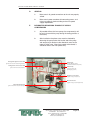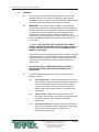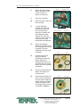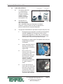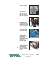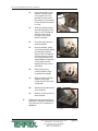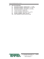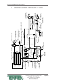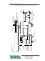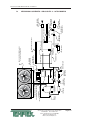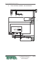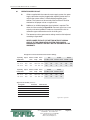
1
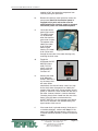
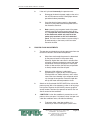
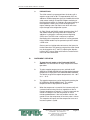
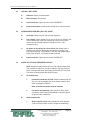
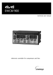
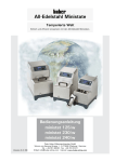
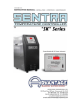
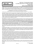
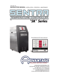
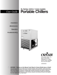
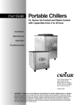
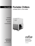
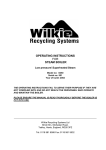
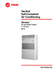
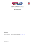
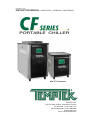
I.O.M. #075 11/05
INSTRUCTION MANUAL
• INSTALLATION • OPERATION • MAINTENANCE
with CF-1 Instrument
TEMPTEK, INC.
525 East Stop 18 Road Greenwood, IN 46142
317-887-0729 fax: 317-881-1277
Service Department fax: 317-885-8683
www.Temptek.com
e-mail: [email protected]
Page: 2
INSTRUCTION MANUAL
CF Series Portable Chiller
5 - 40 Tons
Air-Cooled & Water-Cooled
COVERING
INSTALLATION
OPERATION
MAINTENANCE
TEMPTEK, INC.
525 East Stop 18 Road Greenwood, IN 46142
317-887-0729 fax: 317-881-1277
Service Department fax: 317-885-8683
www.TempTek.com
e-mail: [email protected]
CF Series Portable Chillers with CF-1 Instrument
TABLE OF CONTENTS
1.0
GENERAL
1.1
Introduction
1.2
Unit location
1.3
Efficiency
1.4
Safety
1.5
Clean air act
1.6
Miscellaneous
7
8
8
8
9
9
9
2.0
INSTALLATION
2.1
General
2.2
To and From process connections
2.3
Water supply connection
2.4
Air-cooled condenser
2.5
Water-cooled condenser
2.6
Electrical connection
13
14
14
15
15
17
18
3.0
OPERATIONS
3.1
General
3.2
Start up/operations procedure
3.3
Instrument/operation
3.4
Shut down procedure
21
22
23
26
30
4.0
TROUBLESHOOTING
4.1
Unit Will Not Start
4.2
Compressor Hums But Will Not Start
4.3
Shuts Off On High Pressure
4.4
Shuts Off On Low Pressure
4.5
Compressor Shuts Off On Internal Overload
4.6
Low Or No Process Pressure Or Water Flow
4.7
Cooling Capacity Inadequate
4.8
Sensor
4.9
Coolant Pump
4.10
Crankcase Heater
4.11
Chiller Controller
31
32
32
32
33
34
34
34
35
35
35
35
5.0
MAINTENANCE
5.1
Warranty service procedure
5.2
Periodic preventative maintenance
5.3
Special maintenance
5.4
Solenoid valve service
5.5
Pump seal service
5.6
Checking the refrigerant charge
5.7
Proper cleaning procedure for brazed plate evaporators
37
38
38
39
40
42
45
45
6.0
COMPONENTS
6.1
Water system
6.2
Refrigeration system
47
48
48
525 East Stop 18 Road Greenwood, Indiana 46142
317-887-6352 Fax: 317-881-1277
Service Department Fax: 317-885-8683
Website: www.Temptek.com
Email: [email protected]
Page: 4
CF Series Portable Chillers with CF-1 Instrument
7.0
RELATED DRAWINGS
7.1
Mechanical Schematic : Water-Cooled : 5 - 10 Tons
7.2
Mechanical Schematic : Water-Cooled : 15 - 40 Tons
7.3
Mechanical Schematic : Air-Cooled : 5 - 10 Tons
7.4
Mechanical Schematic : Air-Cooled : 15 - 30 Tons
7.5
Typical Electrical : Air-Cooled
7.6
Typical Electrical : Water-Cooled
7.7
Physical Schematic : Air-Cooled : 7.5 - 10 Tons
7.8
Physical Schematic : Air-Cooled : 5 Tons
7.9
Physical Schematic : Water-Cooled
7.10
Duct Schematic for Air-Cooled Chillers
51
52
53
54
55
56
57
58
59
60
61
8.0
APPENDIX
8.1
Operations below 48°F
8.2
Water quality control
8.3
Inhibited propylene glycol
8.4
Sensor current vs temperature
8.5
Refrigerant pressure-temperature chart
8.6
Chiller capacity and derate chart
63
64
65
65
65
66
67
525 East Stop 18 Road Greenwood, Indiana 46142
317-887-6352 Fax: 317-881-1277
Service Department Fax: 317-885-8683
Website: www.Temptek.com
Email: [email protected]
Page: 5
THIS PAGE INTENTIONALLY BLANK
Page: 6
CF Series Portable Chillers with CF-1 Instrument
1.0
GENERAL
1.1
1.2
1.3
1.4
1.5
1.6
INTRODUCTION
UNIT LOCATION
EFFICIENCY
SAFETY
CLEAN AIR ACT
MISCELLANEOUS
525 East Stop 18 Road Greenwood, Indiana 46142
317-887-6352 Fax: 317-881-1277
Service Department Fax: 317-885-8683
Website: www.Temptek.com
Email: [email protected]
Page: 7
CF Series Portable Chillers with CF-1 Instrument
1.1
1.2
INTRODUCTION
A.
This manual covers portable chillers from 5 to 40 tons.
B.
When calling for assistance from the Manufacturer’s Service
Department, it is important to know the model and serial number of
the particular unit. The model number encodes critical unit
information which is helpful in any attempt to troubleshoot operating
difficulties. The serial number allows the service team to locate
manufacturing and testing records which can have additional
information relating to a particular unit.
UNIT LOCATION
A.
B.
1.3
For air-cooled and water-cooled models:
1.
These units are designed for indoor use only.
2.
For most efficient operation, locate the chiller in a clean, dry
and well ventilated environment.
For air-cooled models:
1.
The unit has an air-cooled refrigerant condenser. For aircooled condensers, a motor driven fan (on models from 5 to
15 tons) or a centrifugal blower (on models from 15 to 30
tons) generates air flow through the condenser to remove
heat from the refrigerant system. The air cooled condenser
on the unit will discharge a maximum of 15,000 BTU’s per
hour per ton of cooling.
2.
The unit must have a minimum entering air temperature of
60°F and a maximum entering air temperature of 95°F for
efficient operation.
3.
The unit must have a minimum of two feet clearance at the
air intake and six feet at the vertical exhaust air discharge.
4.
The unit must have all enclosure panels in place before
operating compressor. Air will not be drawn through the
condenser coil if they are not in place. This will cause the
compressor to lockout on the high pressure safety fault.
EFFICIENCY
A.
Long term efficiency of operation is largely determined by proper
maintenance of the mechanical parts of the unit and the water
quality. The Manufacturer recommends filtering where required to
prevent solids from plugging critical parts (pumps, heaters, seals for
example). The Manufacturer highly recommends the services of a
competent water treatment specialist be obtained and his
525 East Stop 18 Road Greenwood, Indiana 46142
317-887-6352 Fax: 317-881-1277
Service Department Fax: 317-885-8683
Website: www.Temptek.com
Email: [email protected]
Page: 8
CF Series Portable Chillers with CF-1 Instrument
recommendations followed. The Manufacturer accepts no
responsibility for inefficient operation, or damage caused by foreign
materials or failure to use adequate water treatment.
1.4
1.5
1.6
SAFETY
A.
It is important to become thoroughly familiar with this manual and
the operating characteristics of the unit.
B.
It is the owner’s responsibility to assure proper operator training,
installation, operation, and maintenance of the unit.
C.
Observe all warning and safety placards applied to the chiller.
Failure to observe all warnings can result in serious injury or death
to the operator and severe mechanical damage to the unit.
CLEAN AIR ACT
A.
The unit contains HCFC-22 (chlorodifloromethane). This is a class
2 substance.
B.
Effective July 1, 1992, it is unlawful for any person in the course of
maintaining, servicing, repairing, or disposing of refrigeration
equipment to knowingly vent or otherwise dispose of any class 2
substance used as a refrigerant in the manner which permits such
substance to enter the atmosphere.
C.
De minimis releases associated with good faith attempts to
recapture, reclaim or recycle such substance shall not be subject to
the prohibition set forth in the preceding paragraph.
MISCELLANEOUS
A.
The unit is designed to circulate temperature stabilized fluid through
the process resulting in process temperature control.
B.
The ability of the unit to maintain process temperature control is
significantly affected by the method of installation as outline in
section 2 of this manual.
C.
If the operator has any questions concerning the location and
operation of the unit, contact the The Manufacturer’s Service
Department.
525 East Stop 18 Road Greenwood, Indiana 46142
317-887-6352 Fax: 317-881-1277
Service Department Fax: 317-885-8683
Website: www.Temptek.com
Email: [email protected]
Page: 9
CF Series Portable Chillers with CF-1 Instrument
Cover Panel
Pressure Gauges
Instrument
Enclosure Panel
Electrical Panel
Enclosure
Air-Cooled.
Casters
Water-Cooled.
Air Discharge
Protective Fan Shroud
Fan Motor
Hot Gas Bypass Valve
Refrigerant Site Glass
Expansion Valve
Liquid Line Solenoid
Compressor
Insulated Reservoir Tank
Liquid Receiver
Caster
Pump
Air-Cooled Model.
525 East Stop 18 Road Greenwood, Indiana 46142
317-887-6352 Fax: 317-881-1277
Service Department Fax: 317-885-8683
Website: www.Temptek.com
Email: [email protected]
Page: 10
CF Series Portable Chillers with CF-1 Instrument
To Process Connection
From Process Connection
Reservoir
Optional Reservoir Sight Glass
Refrigerant Sight Glass
Condenser Water-Out
Connection
Expansion Valve
Reservoir Make-Up
Connection
Compressor
Electrical Panel
Condenser Water-In Connection
(optional)
Condenser
Condenser Water
Regulator Valve
Make-Up Valve
Pump
Water-Cooled Model.
Caster
525 East Stop 18 Road Greenwood, Indiana 46142
317-887-6352 Fax: 317-881-1277
Service Department Fax: 317-885-8683
Website: www.Temptek.com
Email: [email protected]
Page: 11
THIS PAGE INTENTIONALLY BLANK
Page: 12
CF Series Portable Chillers with CF-1 Instrument
2.0
INSTALLATION
2.1
2.2
2.3
2.4
2.5
2.6
GENERAL
TO AND FROM PROCESS CONNECTIONS
WATER SUPPLY CONNECTION
AIR COOLED CONDENSER INSTALLATION
WATER-COOL CONDENSER INSTALLATION
ELECTRICAL CONNECTION
525 East Stop 18 Road Greenwood, Indiana 46142
317-887-6352 Fax: 317-881-1277
Service Department Fax: 317-885-8683
Website: www.Temptek.com
Email: [email protected]
Page: 13
CF Series Portable Chillers with CF-1 Instrument
2.1
2.2
GENERAL
A.
All process piping materials (such as hose, rigid piping, valves or
filters) used in process water piping circuitry must be rated for
100°F minimum temperature and 100 PSI minimum pressure.
B.
All such materials must have the equivalent or larger diameter of
the particular process connection that length of process water
piping is connected to.
TO AND FROM PROCESS CONNECTIONS
A.
Connect the ‘TO PROCESS’ to the ‘water in’ manifold on the mold
or process.
B.
Connect the ‘FROM PROCESS’ port to the ‘water out’ port on the
process manifold.
C.
Process water piping circuitry should be designed to avoid an
excessive use of elbows and/or lengths of pipe or hose. If hose is
the material of choice, avoid tight twists or curls and excessive
lengths.
D.
Valves and filters may be installed in the process water piping
circuitry to facilitate service and maintenance provided that such
devices maintain the full inside diameter of the process connection.
If installed, all such devices must be open and clean during unit
operation.
From Process :
Connect to ‘Water Out’
port on process manifold
To Process :
Connect to ‘Water In’ port
on process manifold
Water Make-Up :
Connect to plant’s city
water source.
Air-cooled model shown.
525 East Stop 18 Road Greenwood, Indiana 46142
317-887-6352 Fax: 317-881-1277
Service Department Fax: 317-885-8683
Website: www.Temptek.com
Email: [email protected]
Page: 14
CF Series Portable Chillers with CF-1 Instrument
To Process Connection
From Process Connection
Condenser Water-Out Connection
Water Supply Connection
Condenser Water-In Connection
(with optional water regulator valve)
Water-Cooled model shown.
2.3
WATER SUPPLY CONNECTION
A.
2.4
The automatic water supply make-up system continually monitors
the reservoir tank and fills it when needed. Connect as follows:
1.
Connect the chiller’s ‘WATER SUPPLY’ port to the plant’s
city water source.
2.
Minimum water supply pressure requirement is identified on
the equipment data plate. This is normally 20 psi.
3.
Be certain to use a water supply line equipped with a back
flow prevention device to prevent contamination of potable
water.
AIR COOLED CONDENSER
A.
Air-cooled condensers require ambient air temperatures between
60°F and 95°F for efficient operation. Operating above 95°F may
result in elevated condensing pressures and eventual shut-down on
the high pressure safety switch. In such cases, a water assist unit
may be necessary for operations. Air temperatures below 60°F may
result in below normal condensing pressures and poor condensing.
In such cases, a low-ambient damper assembly is required. Check
with the Manufacturer’s service department for more information on
operating with ambients air temperatures above 95°F or below 60°F.
525 East Stop 18 Road Greenwood, Indiana 46142
317-887-6352 Fax: 317-881-1277
Service Department Fax: 317-885-8683
Website: www.Temptek.com
Email: [email protected]
Page: 15
CF Series Portable Chillers with CF-1 Instrument
B.
Air flow is generated by the motor
mounted fans (figure 2.4A) or
centrifugal blowers (figure 2.4B). Air
flow is from the outside of the chiller,
through the condenser and
exhausted through the top of the
unit. On centrifugal blowers models,
exhaust air can be ducted outside of
the plant’s interior environment.
Special duct work is required and a
HVAC contractor should be
consulted for sizing and material
specifications. Exhaust air can not
be ducted on motor mounted fan
models.
C.
A free air space of at least two (2)
feet is required at the condenser
intake and six (6) feet at the
condenser discharge to allow for
proper air flow.
D.
At full load, the chiller will discharge
approximately 15,000 BTU’s per
hour per ton of cooling.
E.
On blower units, air discharge
duct work should be sized by a
qualified HVAC engineer.
Sizing shall be according to
rated CFM at the static
pressure of .90 inches of
water. See figure 2.4C at right.
F.
On blower units, a damper
control assembly is
required in low
ambient temperature
areas or when
outdoor air make-up
is used. The
assembly works in
conjunction with
refrigerant head
pressure to regulate
air flow to maintain
proper refrigerant
head pressure when
condenser intake air
temperature will be
less than 60°F. See
figure 2.4D to the
right.
Typical fan assembly
Figure 2.4A
Typical blower assembly
Figure 2.4B
525 East Stop 18 Road Greenwood, Indiana 46142
317-887-6352 Fax: 317-881-1277
Service Department Fax: 317-885-8683
Website: www.Temptek.com
Email: [email protected]
Figure 2.4C
Figure 2.4D
Page: 16
CF Series Portable Chillers with CF-1 Instrument
G.
2.5
All air cooled units must have all enclosure panels in place before
operating compressor. Air will not be drawn through the condenser
coil if they are not in place. This will cause the compressor to
lockout on the high pressure safety fault.
WATER-COOLED CONDENSER
A.
B.
Connect the ‘CONDENSER WATER
IN’ port to the plant’s city water
supply or tower system supply.
1.
Required consumption from
a city water source is 1.5
gpm at 65°F per ton of rated
capacity.
2.
Required consumption for a
tower water source is 3 gpm
at 85°F per ton of rated
capacity.
Typical condenser connections 30 ton unit
Figure 2.5A
Connect the chiller’s ‘CONDENSER WATER OUT’ port to the
plant’s drain or tower system return.
1.
Note: if dumping to the plant’s open drain, drainage shall
be done according to local codes.
C.
The pressure differential requirement between the condenser “water
in” and the condenser “water out” lines must be 30 psi for adequate
efficiency.
D.
The installation of a strainer in the
condenser “water in” line is
recommended. This removes solids
from the water supply and serves to
protect the water saver (regulator)
valve.
E.
The water saver (regulator) valve
(figure 2.5B) is located in the
condenser “water in” line. During
winter months, or cold seasons, the
Optional Regulator Valve
Figure 2.5B
valve will throttle the water flow
through the condenser. The amount
of flow is based on the refrigerant head pressure and the regulator
will modulate the valve orifice to maintain 100° - 105°F condensing
temperature for best efficiency*.
* See Temperature-Pressure
chart in Section 8.5 for
refrigerant pressure.
525 East Stop 18 Road Greenwood, Indiana 46142
317-887-6352 Fax: 317-881-1277
Service Department Fax: 317-885-8683
Website: www.Temptek.com
Email: [email protected]
Page: 17
CF Series Portable Chillers with CF-1 Instrument
2.5
ELECTRICAL CONNECTION
A.
NEMA 1 MODELS
1.
2.
3.
B.
Electrical power supply requirements for Nema 1 units are
identified on the equipment data plate. Determine the plant’s
voltage supply is the same as the unit’s voltage
requirements.
WARNING: Do not connect the unit to a voltage supply
not equal to the unit’s voltage requirements as
specified on the unit’s data plate. Use of incorrect
voltage will void the unit’s warranty and cause a
significant hazard that may result in serious personal
injury and unit damage.
A customer supplied, four conductor cable is required for
connection to a customer supplied fused disconnecting
means. The fused disconnecting means shall be sized and
installed according to the unit’s power supply requirements
and local electrical codes.
Connect the four conductor power cable to power entry
terminal block on the unit’s electrical panel. Then connect
the power cable to the fused disconnect switch.
NEMA 12 MODELS
1.
NEMA 12 units are constructed with a dust tight electrical
enclosure and branch circuit fusing. Electrical power supply
requirements are identified on the equipment data plate.
Determine the plant’s voltage supply is the same as the
unit’s voltage requirements.
WARNING: Do not connect the unit to a voltage supply
source not equal to the unit’s voltage requirements as
specified on the unit’s data plate. Use of incorrect
voltage will void the unit’s warranty and cause a
significant hazard that may result in serious personal
injury and unit damage.
C.
2.
Appropriate conduit and fittings should be selected which
will maintain the integrity of the cabinet.
3.
Supply a power conductor sized according to the unit’s
power supply requirements. Connect the power conductor to
the unit’s power supply entry terminal block or the fused
disconnect switch. Some Nema 12 models may be supplied
with an optional disconnect switch. The owner supplied
fused disconnecting means shall be sized and installed
according to the unit’s power supply requirements and local
electrical codes.
CONTROL CIRCUIT WIRING
1.
The unit’s supplied control circuit is 110 volt, 1 phase, 60
cycle. The control circuit is supplied by the factory installed
transformer. An inline control circuit fuse is provided.
525 East Stop 18 Road Greenwood, Indiana 46142
317-887-6352 Fax: 317-881-1277
Service Department Fax: 317-885-8683
Website: www.Temptek.com
Email: [email protected]
Page: 18
CF Series Portable Chillers with CF-1 Instrument
D.
E.
GENERAL
1.
Make certain all ground connections to the unit are properly
affixed.
2.
Make certain power conductor, disconnecting means, and
fusing are properly sized according to the unit’s power
supply requirements.
INFORMATION REGARDING ‘PHASING’ OF SCROLL
COMPRESSORS
1.
All portable chillers that have pumps, the compressor(s) will
be set in phase with the pump during the testing process at
the factory.
2.
After installation the phase status must be checked by
observing the pump motor shaft on the end of the pump
and comparing its rotation to the directional arrow on the
motor. In either case, if the phase needs to be altered, it
should be done at the main power entry.
Refrigerant High Pressure Limit
Transformer
(protects from excessive condensing pressures)
(provides different voltages
to instrument and other components)
Refrigerant Low Pressure Limit
Power Entry
(protects from low suction pressures)
(connect to power cord grounding lug on panel)
Compressor Contactor
(supplies voltage to compressor)
Motor Contractor
(supplies voltage to coolant pump motor)
Motor Overload Relay
(protects motor from excessive amperage)
Figure 2.5A Typical electrical panel
525 East Stop 18 Road Greenwood, Indiana 46142
317-887-6352 Fax: 317-881-1277
Service Department Fax: 317-885-8683
Website: www.Temptek.com
Email: [email protected]
Page: 19
THIS PAGE INTENTIONALLY BLANK
Page: 20
CF Series Portable Chillers with CF-1 Instrument
3.0
OPERATIONS
3.1
3.2
3.3
3.4
GENERAL
START UP/OPERATIONS PROCEDURE
INSTRUMENT
SHUT DOWN
525 East Stop 18 Road Greenwood, Indiana 46142
317-887-6352 Fax: 317-881-1277
Service Department Fax: 317-885-8683
Website: www.Temptek.com
Email: [email protected]
Page: 21
CF Series Portable Chillers with CF-1 Instrument
3.1
GENERAL
A.
Failure to follow the factory required operations procedure may
adversely affect the unit’s ability to adequately control process
temperature and may create a hazardous operating condition which
may result in serious operator injury and/or unit damage.
B.
IMPORTANT: if this unit contains a hermetic or semi-hermetic
reciprocating compressor it is equipped with a crankcase heater on
the compressor. While the compressor is idle, the crankcase heater
prevents freon vapor from migrating to and condensing in the
compressor crankcase. If freon is allowed to condense in the
crankcase, it can be drawn into the cylinders upon start up. This can
cause catastrophic damage to the connecting rods, pistons, and
valve plates.
To avoid this, BEFORE THE UNIT IS STARTED, THE POWER
SUPPLY SHOULD BE APPLIED TO THE UNIT FOR AT LEAST 12
HOURS, OR UNTIL THE BOTTOM OF THE COMPRESSOR IS
WARM TO THE TOUCH.
If the power has been disconnected more than two hours, the power
should be applied for six hours before restarting. Power should be
applied to the unit continuously, except for service purposes. The
crankcase heater should be checked for proper operation on a
regular basis.
UNITS WITH SCROLL COMPRESSORS DO NOT HAVE A
CRANKCASE HEATER AND THIS PROCEDURE IS NOT
NECESSARY.
C.
The OPERATIONS segment of this manual is divided into the
following sections:
3.2
Start up/operations - follow this segment to start the unit
after the initial install to the process system or to restart the
unit after reinstallation to the same or different process
system. This section includes information on system fill,
electric motor phasing (pump rotation) and process flow
adjustments.
3.3
Chiller Control - follow this segment to start up and
operate the chiller control. This section includes information
on setpoint selection and adjustment, and feature
explanations.
3.4
Shut down procedure - follow this segment to shut down
the unit. This segment includes information on system shut
down, electrical power supply precautions, and
disconnection from system.
525 East Stop 18 Road Greenwood, Indiana 46142
317-887-6352 Fax: 317-881-1277
Service Department Fax: 317-885-8683
Website: www.Temptek.com
Email: [email protected]
Page: 22
CF Series Portable Chillers with CF-1 Instrument
3.2
START UP / OPERATION PROCEDURE
A.
B.
SYSTEM FILL
1.
The unit has an internal reservoir which must be filled and
maintained for proper operation. The unit has a level switch
mounted at the proper water level in the reservoir.
2.
WATER QUALITY CONTROL. Lack of, as well as, improper
water treatment can damage the chilling unit. The services
of competent water treatment specialist should be obtained
and their recommendations followed. It is the equipment
owner’s responsibility to prevent damage from foreign
material or inadequate water treatment. See water
treatment section in section 8 of this manual for more
information.
3.
FOR OPTIONAL
AUTOMATIC FILL: engage
the water supply to unit. The
level switch will activate the
make-up solenoid (figure
3.2A), which will open and
the water supply will fill the
reservoir tank.
4.
MANUAL FILL: disconnect
the electrical power supply
and remove all necessary
cover panels to access the
reservoir. Add fluid directly to
the reservoir. When the
pump is first started, as
process lines are filled and
air is purged, additional fluid
may be required to restore
the reservoir to the correct
level. Verify reservoir level
via the coolant sight glass
(figure 3.2B).
Make-up solenoid valve
Figure 3.2A
Typical reservoir sight glass
Figure 3.2B
ELECTRIC MOTOR PHASING (PUMP ROTATION)
1.
The operator must determine the unit is phased correctly by
visually inspecting the rotation of the pump motor shaft. The
procedure is outlined below. Incorrect phasing results in
poor operation and eventual damage to the unit.
a.
Supply electrical power to the unit. Once the correct
voltage is supplied to the unit, the POWER switch
on the unit’s control panel will illuminate. Adjust the
525 East Stop 18 Road Greenwood, Indiana 46142
317-887-6352 Fax: 317-881-1277
Service Department Fax: 317-885-8683
Website: www.Temptek.com
Email: [email protected]
Page: 23
CF Series Portable Chillers with CF-1 Instrument
setpoint to 70°F to prevent the compressor from
activating during this procedure.
b.
Remove all necessary cover panels to access the
pump motor. Note that the electrical power is
engaged at this point and caution must be
observed while the electrical supply is engaged
and cabinet panels are removed and opened.
c.
Locate the electric
motor (figure 3.2C).
The electric motor
can be identified
when the electrical
panel cover is open.
The operator must
identify the motor
shaft inside the
electric motor
housing. The motor
Electric motor
Figure 3.2C
shaft can be seen
through the vent slots in the motor housing or by
removing the shaft cover.
d.
Toggle the
illuminated ON/OFF
SWITCH (figure
3.2D). This will
quickly cycle the
pump motor “on”
and then “off”.
e.
Observe the motor
shaft. When the
ON/OFF SWITCH is Illuminated On/Off switch
Figure 3.2D
on, the motor shaft
will rotate. When
switched off, the shaft will slowly “coast” to a stop.
As the shaft slows, the operator can identify the
rotation of the motor shaft. Correct rotation (correct
phase) is “clockwise”, when viewed from the rear of
the motor. Incorrect rotation is “counter-clockwise”
(incorrect phase) when viewed from the rear of the
motor. If the shaft does not rotate when the
ON/OFF SWITCH is on, the operator must identify
the cause as outlined in the troubleshooting and
repair section of this manual.
f.
If the motor shaft is phased correctly (shaft turns in
a clockwise direction), continue with step C. If the
motor shaft is NOT phased correctly (shaft turns in
a counter-clockwise direction), correct as outlined in
step 2.
525 East Stop 18 Road Greenwood, Indiana 46142
317-887-6352 Fax: 317-881-1277
Service Department Fax: 317-885-8683
Website: www.Temptek.com
Email: [email protected]
Page: 24
CF Series Portable Chillers with CF-1 Instrument
2.
C.
If the unit is phased incorrectly, the operator must:
a.
Disengage the electrical power supply to the unit at
the unit’s disconnect switch. Follow proper lockout
procedures before proceeding.
b.
Once the electrical power supply is disengaged,
reverse any two power leads of the power cord at
the disconnect terminals.
c.
Note: reversing any two power leads of the power
cord will correctly phase the power supply to the
unit. The operator must reverse the power leads
at the disconnect switch only and not at the
power entry terminals on the unit’s electrical
panel. The unit’s internal electrical system wiring is
phased correctly at the factory and must not be
altered in the field.
PROCESS FLOW ADJUSTMENTS
1.
2.
3.
The operator must determine and set proper water flow rate
for the most efficient and trouble free operation.
a.
Water flow rate through the process is determined
by the pressure losses in the process loop.
Generally, higher flow rates result in turbulent flow
achieving maximum temperature control and lower
maintenance. Since the evaporator in most liquid
chillers is flow sensitive, the efficiency of operation
is directly related to the flow of liquid.
b.
Maximum chiller efficiency is obtained at
approximately 2.4 gpm per ton of rated capacity.
Low liquid flow can reduce efficiency and in some
cases allow ice to develop in the evaporator which
can damage the evaporator. Excessive liquid flow
will trip the motor overload protection circuit.
Switch on the illuminated ON/OFF SWITCH to activate the
process pump. Wait a few moments to allow air to be purge
from system. Observe the COOLANT pressure gauge for
steady readout. Two items the operator for look for are low
flow or excessive flow conditions.
LOW FLOW: If a low flow condition is present, be sure all
process valves are open. If all process valves are open and
a low flow conditions exists, consider the following:
a.
To operate under a low flow condition, it is
necessary to install a flow bypass system in the
525 East Stop 18 Road Greenwood, Indiana 46142
317-887-6352 Fax: 317-881-1277
Service Department Fax: 317-885-8683
Website: www.Temptek.com
Email: [email protected]
Page: 25
CF Series Portable Chillers with CF-1 Instrument
process circuitry. This will allow a portion of the flow
to bypass the process and return directly to the
chiller. This keeps the total flow above the cutoff
point. Figure 3.2E illustrates a typical bypass loop.
Figure 3.2E Typical low flow by-pass loop
b.
3.3
Some models may have a factory installed bypass.
Adjust the valve accordingly.
INSTRUMENT/OPERATION
Figure 3.3A
CF-1 Chiller Control.
A.
INSTRUMENT START-UP
1.
When the correct electrical power and adequate water
supply pressure are supplied to the unit, it is possible to
start the unit.
2.
Upon power up, the instrument displays “ChF” indicating
that the unit is in Fahrenheit temperature mode or “ChC”
indicating that it is in Celsius mode. The control then shows
the current setpoint for approximately 2 seconds before
reverting to the To Process temperature. When power is
supplied to the unit, the ON/OFF switch will illuminate.
525 East Stop 18 Road Greenwood, Indiana 46142
317-887-6352 Fax: 317-881-1277
Service Department Fax: 317-885-8683
Website: www.Temptek.com
Email: [email protected]
Page: 26
CF Series Portable Chillers with CF-1 Instrument
3.
PRECAUTIONS:
The chiller control is programmed from the factory with a
setpoint range of 48° to 90°F. To operate below 48°F, the
addition of inhibited propylene glycol and modification of the
safety control settings are required. Diligent monitoring of
the water/glycol solution is mandatory to prevent freezing of
the evaporator. Freezing may cause the evaporator to
rupture allowing water and freon to mix which will cause
major damage to the refrigeration system.
On R22, R134A and R407C models operating above 70°F
and R404A models operating above 60°F requires the
addition of a refrigerant crankcase pressure regulating
(CPR) valve. The CPR valve is necessary to prevent
overloading of the compressor which can cause premature
failure. R410A models may be operated up to 80°F without
a CPR valve.
Contact your local refrigeration contractor or the factory for
further information. The operating range of the chiller control
may be changed to 10°F - 90°F by adjusting the Setpoint
Lockout (SPL) jumper. Refer to the technical section of this
manual for more information.
B.
INSTRUMENT OPERATION
1.
To start the unit, toggle on the illuminated ON/OFF
SWITCH. The chiller control will begin temperature control
operations.
2.
To select setpoint temperature, press and hold the UP
ARROW or DOWN ARROW keys until the desired set point
temperature is displayed in the TEMPERATURE WINDOW.
The default range for the setpoint temperature is 48° - 90°F
or 9° - 32°C.
3.
The setpoint temperature can be displayed by pressing the
UP ARROW or DOWN ARROW keys. The setpoint
temperature will be displayed for 5 seconds.
4.
When the compressor is turned off, the instrument will wait
3 minutes before turning it back on regardless of the To
Process temperature or setpoint. If a fault has occurred, the
control will attempt to turn the compressor on after 3
minutes powered down. If the fault condition remains, the
control will turn the compressor off and retry after 1 minute.
This sequence will repeat until the compressor turns on or
instrument power is cycled.
525 East Stop 18 Road Greenwood, Indiana 46142
317-887-6352 Fax: 317-881-1277
Service Department Fax: 317-885-8683
Website: www.Temptek.com
Email: [email protected]
Page: 27
CF Series Portable Chillers with CF-1 Instrument
5.
Under normal conditions (no fault conditions, compressor
has been off for three minutes) the instrument will turn on
the compressor when the To Process temperature is above
the setpoint.
The instrument will turn on the hot gas bypass when the To
Process temperature is below the setpoint by no more than
3 degrees.
The instrument will turn off the compressor and hot gas
bypass when the To Process temperature is 4 degrees or
more below the setpoint.
C.
INSTRUMENT CONTROLS
1.
ILLUMINATED ON/OFF SWITCH: this rocker switch starts
or stops the unit. Electrical power is supplied to the unit
when the switch is illuminated.
2.
UP ARROW and DOWN ARROW KEYS: depress and hold
this push button to increase (UP ARROW) or decrease
(DOWN ARROW) the setpoint temperature. If the push
button is pressed momentarily the setpoint value is
incremented or decremented by one degree. If the push
button is held down the setpoint will increase or decrease
continously.
3.
SETPOINT LOCK OUT JUMPER: this jumper controls
whether the user is allowed to reduce the setpoint below
48°F or 9°C. If the jumper is in position 1 (farthest from the
SPL label) the user IS NOT ALLOWED to reduce the
setpoint below 48°F or 9°C. If the jumper is in position 2
(closest to the SPL label) the user is allowed to reduce the
setpoint to 10°F or -11°C.
4.
TEMPERATURE DISPLAY JUMPER: if this jumper is in the
“F” position, the To Process and Setpoint temperatures are
displayed in Fahrenheit. If the jumper is in the “C” position,
the To Process and Setpoint temperatures are displayed in
Celsius.
5.
Probe Calibration: this pot (CALPOT 1) is used to calibrate
the probe circuit.
Figure 3.3B
Setpoint Lock Out Jumper
Temperature Display Jumper
Probe Calibration
525 East Stop 18 Road Greenwood, Indiana 46142
317-887-6352 Fax: 317-881-1277
Service Department Fax: 317-885-8683
Website: www.Temptek.com
Email: [email protected]
Page: 28
CF Series Portable Chillers with CF-1 Instrument
D.
STATUS LIGHTS
1.
COMPRESSOR: illuminates when compressor is turned on.
2.
CAPACITY CONTROL: illuminates when capacity control
system is turned on.
3.
REFRIGERANT FAULT: illuminates when there is a high
pressure or low pressure alarm. Check troubleshooting
section of this manual for more details.
High Pressure Alarm. If the chiller control detects a high
pressure condition it will immediately turn off the
compressor and hot gas bypass.
Low Pressure Alarm. After
the compressor is turned on,
the control has a 15 second
buffer for the low pressure
alarm. If a low pressure
condition occurs within the
first 15 seconds, the control
waits the amount of time
specified by the “LP TIME”
potentiometer before
indicating an alarm and
Low Pressure Potentiometer.
Figure 3.3C
turning off the compressor. If
the condition is corrected
before the time expires, no alarm occurs. If a low pressure
condition occurs 15 seconds after the compressor turns on,
the instrument waits 20 seconds before indicating an alarm
and turning off the compressor.
E.
F.
TEMPERATURE DISPLAY
1.
A three digit display window indicates the appropriate
temperature. The window also displays the numeric value
for the setpoint temperature.
2.
The To Process temperature is always displayed unless a
button has been pressed. If there is a probe error, the
display will show three dashes “---”.
PRESSURE GAUGES (OPTIONAL)
1.
PROCESS PRESSURE GAUGE: indicates process pump
pressure.
2.
REFRIGERANT HEAD PRESSURE GAUGE: indicates
refrigerant pressure on the discharge side of the
compressor. This is the condensing pressure which is
525 East Stop 18 Road Greenwood, Indiana 46142
317-887-6352 Fax: 317-881-1277
Service Department Fax: 317-885-8683
Website: www.Temptek.com
Email: [email protected]
Page: 29
CF Series Portable Chillers with CF-1 Instrument
critical to equipment efficiency. Head pressure on water
condensed units will vary with ambient temperatures
between 190-290 psig.
3.
3.4
LOW PRESSURE GAUGE: indicates refrigerant pressure
on the suction side of the compressor. This pressure will
fluctuate with the process temperature.
SHUT DOWN/DISCONNECT SEQUENCE
A.
PRECAUTIONS/WARNINGS
1.
B.
The operator must precisely follow all shut down procedures
outlined in this manual. If the operator fails to follow
precisely all procedures outlined in this manual, an unsafe
condition can develop resulting in damage to the unit or
personal injury.
UNIT SHUT DOWN
1.
2.
To shut down the unit without disconnecting from the
process:
a.
Move the ON / OFF switch to the off position.
b.
Maintain electrical power to the unit at all times
except for service purposes.
To shut down the unit and disconnect from the
process:
a.
Move the ON / OFF switch to the off position.
b.
Disengage the electrical supply to the chiller at the
disconnecting device.
c.
Disconnect all process lines.
525 East Stop 18 Road Greenwood, Indiana 46142
317-887-6352 Fax: 317-881-1277
Service Department Fax: 317-885-8683
Website: www.Temptek.com
Email: [email protected]
Page: 30
CF Series Portable Chillers with CF-1 Instrument
4.0
TROUBLESHOOTING
4.1
4.2
4.3
4.4
4.5
4.6
4.7
4.8
4.9
4.10
4.11
UNIT WILL NOT START
COMPRESSOR HUMS BUT WILL NOT START
SHUTS OFF ON HIGH PRESSURE
SHUTS OFF ON LOW PRESSURE
COMPRESSOR SHUTS OFF ON INTERNAL OVERLOAD
LOW OR NO PROCESS PRESSURE OR WATER FLOW
COOLING CAPACITY INADEQUATE
SENSOR
PUMPS
CRANKCASE HEATER
CHILLER CONTROLLER
525 East Stop 18 Road Greenwood, Indiana 46142
317-887-6352 Fax: 317-881-1277
Service Department Fax: 317-885-8683
Website: www.Temptek.com
Email: [email protected]
Page: 31
CF Series Portable Chillers with CF-1 Instrument
4.1
4.2
4.3
UNIT WILL NOT START
A.
Power off. Check main disconnect.
B.
Main line open. Check fuses.
C.
Loose terminals. Tighten terminals with POWER OFF.
D.
Control circuit open. check control voltage fuses and transformer.
COMPRESSOR HUMS BUT WILL NOT START
A.
Contactor. Check contacts and contactor operation.
B.
Low voltage. Check voltage at main and at the unit. If voltage is OK
at the main but low at the unit, increase wire size. If low at main,
consult your local power company. Voltage must be +/- 10%
nameplate rating.
C.
No power on one phase of a three phase unit. Check fuses in
control panel and main disconnect. Also check unit wiring, main
plant fuse and wiring. If the problem is with the main power supply
coming into the plant, call the local power company.
D.
Loose terminals. Tighten terminals with POWER OFF.
SHUTS OFF ON HIGH PRESSURE CONTROL
Note. Refrigerant high pressure will vary with ambient temperature
from minimum of 190 psi to as high as 280 psi. The high pressure
switch manually reset when discharge pressure falls to a safe level.
The switch is located inside the electrical panel.
A.
Air-cooled units:
1.
Insufficient condenser air flow. Check condenser filter for
dirt, fins may be plugged with dirt or foreign material. Also,
check for proper fan rotation.
Note: all enclosure panels must be attached.
2.
B.
Fan motor not operating. Have electrician check fuses
and wiring, motor starter and overloads, and motor. Repair
or replace motor if defective.
Water-cooled units:
1.
Water regulator valve. Adjust condenser water regulator
valve to maintain 100°F to 105°F refrigerant condensing
525 East Stop 18 Road Greenwood, Indiana 46142
317-887-6352 Fax: 317-881-1277
Service Department Fax: 317-885-8683
Website: www.Temptek.com
Email: [email protected]
Page: 32
CF Series Portable Chillers with CF-1 Instrument
temperature*. If valve is defective, have valve repaired or
replaced by a refrigeration serviceman.
* See Temperature-Pressure
chart in Section 8.5 for
refrigerant pressure.
C.
4.4
2.
Insufficient condenser water flow. Check condenser
water pumping system.
3.
Condenser water temperature too high. Check cooling
tower or proper operation city water temperature.
4.
Condenser water tubes scaled. Clean with brushes and
chemicals approved by the Advantage Service Department.
Improperly set high pressure control. Have refrigeration
serviceman reset or replace the control if defective.
SHUTS OFF ON LOW PRESSURE CONTROL
Note:
* See Temperature-Pressure
chart in Section 8.5 for
refrigerant pressure.
The low pressure switch will automatically resets when the pressure
rises above the cut-in pressure. If this does not occur contact the
the Manufacturer’s service department for instructions.
The low pressure switch is set to cut-out at 32°F and cut-in at
36°F - 39°F*. If a low pressure condition exists for more than five
seconds the compressor will stop and a “L-P” fault will appear in
the display window.
After the refrigerant pressure rises above the cut-in pressure, a
three minute time delay will occur before the compressor restarts.
This will protect the evaporator and compressor from damage
should a problem occur in the refrigeration system or if the chiller is
operated under circumstances which could cause damage to the
refrigeration system.
A.
Air-cooled units:
Head pressure too low. Check that entering air
temperature is above 60°F. If below 60°F, find out reason
why.
B.
* See Temperature-Pressure
chart in Section 8.5 for
refrigerant pressure.
C.
Water-cooled units:
Head pressure too low. Adjust condenser water regulating
valve to maintain 100°F - 105°F refrigerant condensing
temperature*. Have refrigeration serviceman repair valve
or replace if defective.
Low refrigerant charge. Check for adequate refrigerant charge
(bubbles or misty sight glass indicates low charge). If charge is low,
have system checked for leaks and recharged by a refrigeration
serviceman.
525 East Stop 18 Road Greenwood, Indiana 46142
317-887-6352 Fax: 317-881-1277
Service Department Fax: 317-885-8683
Website: www.Temptek.com
Email: [email protected]
Page: 33
CF Series Portable Chillers with CF-1 Instrument
4.5
D.
Improperly set low pressure switch. Have a refrigeration
serviceman reset control or replace if defective.
E.
Restriction in the liquid line.
2.
Liquid line valve or suction valve on
compressor is partially closed. Open fully.
3.
Liquid line solenoid not opening fully or leaking
during off cycle. have repaired or replaced if
defective by a refrigeration serviceman.
4.
Expansion valve plugged or inoperative. Check
thermal bulb and capillary tube for damage. Have
repaired or replaced if defective by a refrigeration
serviceman.
Control does not reset. Have compressor windings and internal
solid state safety control checked by a refrigeration serviceman.
Have it repaired or replace if defective.
LOW OR NO PROCESS PRESSURE OR WATER FLOW
A.
Valves. Check if water valves are open.
B.
Pump. Check pump for correct rotation. Check pump suction for
restriction. Replace motor if defective.
Filters. Check filter in the chilled water circuit and clean if
necessary.
C.
4.7
Clogged filter drier. Check for pressure or
temperature drop and have drier core replaced by a
refrigeration serviceman.
COMPRESSOR SHUTS OFF ON INTERNAL OVERLOAD
A.
4.6
1.
D.
Pressure switch (or flow switch). Readjust or replace if defective.
E.
Fuses and wiring. Have electrician check the fuses and wiring.
COOLING CAPACITY INADEQUATE
A.
Low refrigerant charge. Check for adequate refrigerant charge
(bubbles or misty sight glass indicates low charge). If charge is low,
have system checked for leaks and recharged by a refrigeration
serviceman.
B.
Hot-gas bypass valve stuck open. Have repaired or replace if
defective by a refrigeration serviceman.
525 East Stop 18 Road Greenwood, Indiana 46142
317-887-6352 Fax: 317-881-1277
Service Department Fax: 317-885-8683
Website: www.Temptek.com
Email: [email protected]
Page: 34
CF Series Portable Chillers with CF-1 Instrument
4.8
C.
Expansion valve plugged or inoperative. Check thermal bulb and
capillary tube for damage. Have repaired or replaced if defective by
a refrigeration serviceman.
D.
Plugged filter. Check filter in chilled water circuit and clean.
E.
Air in system. Purge air.
SENSOR
The sensor is a solid state temperature transducer which converts
temperature input to proportional current output. To quickly test for a
defective probe, switch connections between the defective probe
and a probe known to be working properly. A defective sensor will
display a “---” in the display window on the instrument control.
4.9
4.10
4.11
COOLANT PUMP
A.
The centrifugal pump is designed to operate at a specific flow and
pressure at the maximum run load amp draw of the motor. Too
much flow can overload the motor and cause the overload circuit to
open and stop the pump.
B.
If the overload trips, check for electrical shorts, loose wires, or
blown fuses. If these check OK, reset the overload circuit and
restart the chiller.
C.
Check the amp draw and if overloaded, partially close the from
process line valve until the amp draw drops to the proper level.
CRANKCASE HEATER
A.
If the crankcase heater is not drawing current during the
compressor off cycle, check for a defective crankcase heater,
defective fuses or defective interlock on the compressor starter.
B.
Scroll compressors do not have crankcase heaters.
CHILLER CONTROLLER
A.
The display is used for all normal set ups, diagnostics, temperature
readout, and operational information. Note: the display is not field
repairable. It can be easily removed and replaced if required.
B.
The CPU contains the software and various electronic components
which make the instrument work. Note: the CPU is not a field
repairable part. It can be easily removed and replaced if a problem
arises.
525 East Stop 18 Road Greenwood, Indiana 46142
317-887-6352 Fax: 317-881-1277
Service Department Fax: 317-885-8683
Website: www.Temptek.com
Email: [email protected]
Page: 35
THIS PAGE INTENTIONALLY BLANK
Page: 36
CF Series Portable Chillers with CF-1 Instrument
5.0
MAINTENANCE
5.1
5.2
5.3
5.4
5.5
5.6
5.7
WARRANTY SERVICE PROCEDURE
PERIODIC PREVENTATIVE MAINTENANCE
SPECIAL MAINTENANCE
SOLENOID VALVE SERVICE
PUMP SEAL SERVICE
CHECKING THE REFRIGERANT CHARGE
PROPER CLEANING PROCEDURE FOR BRAZED PLATE EVAPORATOR
525 East Stop 18 Road Greenwood, Indiana 46142
317-887-6352 Fax: 317-881-1277
Service Department Fax: 317-885-8683
Website: www.Temptek.com
Email: [email protected]
Page: 37
CF Series Portable Chillers with CF-1 Instrument
5.1
5.2
WARRANTY SERVICE PROCEDURE
A.
In the event of a problem with a chiller that can not be resolved by
normal troubleshooting procedures, the customer is invited to
consult the Service Department for assistance. The correct model
number and serial number of the chiller must be available. The
service department will attempt to isolate the problem and advise
repair procedures. Often times, with the customer’s input and with
the machine diagnostics, problems can be determined with “overthe-phone” consultation.
B.
If the problem is beyond the scope of “over-the-phone” consultation,
and if the warranty status of the machine is valid, the Manufacturer
will contact the nearest authorized service contractor and provide
authorization to conduct an “on-site” inspection of the unit in order
to determine the course of repair. If the chiller is not covered by the
warranty, the Manufacturer will advise on the repair and recommend
available service contractors.
C.
It is of the utmost importance that you provide the correct model
number and serial number of the machine in question. This will
allow the Service Department to obtain the correct manufacturing
records which will help to properly troubleshoot the problem and
obtain the proper replacement parts when they are required. This
information is stamped on the data tag that is attached to the
electrical enclosure of each machine.
D.
The Service Department must be notified prior to any repair or
service of a warranty nature. Warranty claims will not be honored
without prior authorization.
PERIODIC PREVENTATIVE MAINTENANCE
A.
Lubricate all motors. Note that some motors are supplied with
sealed bearings.
B.
Tighten all wire terminals.
C.
Clean and check motor starter and contactor contacts.
D.
Check safety switch settings.
E.
Clean condenser fins of dust and dirt (air cooled models only).
F.
Back flush evaporator.
G.
Check glycol/water solution ratio for operating temperature.
H.
Check system for leaks.
525 East Stop 18 Road Greenwood, Indiana 46142
317-887-6352 Fax: 317-881-1277
Service Department Fax: 317-885-8683
Website: www.Temptek.com
Email: [email protected]
Page: 38
CF Series Portable Chillers with CF-1 Instrument
5.3
I.
Refrigerant sight glass: check for bubbles when compressor is
operating at 100%. Check the moisture indicator for a color other
than green.
J.
Clean unit.
SPECIAL MAINTENANCE
A.
Any service of the refrigeration system must be accomplished by a
certified refrigeration technician.
1.
Addition of compressor oil.
2.
Addition of refrigerant.
3.
Repair of a refrigerant leak.
4.
Adjustment of super heat.
5.
Changing of filter-drier or drier core.
6.
Repair of a refrigeration solenoid.
525 East Stop 18 Road Greenwood, Indiana 46142
317-887-6352 Fax: 317-881-1277
Service Department Fax: 317-885-8683
Website: www.Temptek.com
Email: [email protected]
Page: 39
CF Series Portable Chillers with CF-1 Instrument
5.4
SOLENOID VALVE SERVICE
A.
Units with the optional water
make-up system use a solenoid
valve (figure 5.4A) to regulate flow
into the reservoir tank. The solenoid
valve is controlled by the float
switch.
B.
Generally, solenoid valves fail due
to poor water quality, low water
flow, or defective valve elements.
C.
The operator should follow this
procedure to service the make-up
solenoid valve:
Typical water make-up
solenoid valve
Figure 5.4A
1.
Disengage process operations according to the procedure
outlined in section 3.4. The operator must be certain
process fluid temperature is under 100°F and pressure is
relieved (pressure gauge reads “0”) and water system flow
is shut off and all pressure relieved.
2.
Disengage main power supply. The operator must verify the
proper lockout procedures are followed.
3.
Remove or open any access cover panel and set aside to
gain access to the cooling solenoid valve.
4.
The operator must be certain all water system pressure is
relieved.
5.
Identify the retaining screw
(figure 5.4B) on the
solenoid valve coil. Remove
the screw. Keeping all
electrical connections
intact, lift the coil off of the
enclosure tube and set
aside.
6.
Use a pair of channel lock
pliers or a pipe wrench to
Coil
Figure 5.4B
separate the bonnet
assembly from the valve body.
The plunger is “loose” inside the enclosing tube. Be certain
it is retained in the enclosure tube as the bonnet is removed
(figure 5.4C).
7.
Identify the diaphragm assembly. Gently remove the
assembly from the valve body (figure 5.4D).
Retaining screw
525 East Stop 18 Road Greenwood, Indiana 46142
317-887-6352 Fax: 317-881-1277
Service Department Fax: 317-885-8683
Website: www.Temptek.com
Email: [email protected]
Page: 40
CF Series Portable Chillers with CF-1 Instrument
8.
Identify the mesh screen.
Gently removed the mesh
screen and clean or
replace as necessary.
9.
Clean the valve body.
10.
Reset the mesh screen into
the valve body.
11.
If a new diaphragm
assembly was obtained,
continue with step 12. If
not, disassemble the
diaphragm assembly and
note component order
(figure 5.4E). Clean the
valve port, plate, collar and
O-ring. Once cleaned,
reassemble the diaphragm.
12.
Set the reassembled
diaphragm assembly or the
new assembly back into the
valve body. The stem
should be facing out of the
valve body.
13.
Inset the plunger with
spring first into the
enclosing tube of the top
bonnet (figure 5.4F).
Holding the plunger in the
enclosure tube, set the top
bonnet onto the valve body
and tighten.
14.
Place the coil onto the top
bonnet and replace the
retaining screw.
15.
Open the water supply and
drain valves (if installed) to
circulate water through the
supply and drain manifolds.
Check the solenoid valve
for leakage. Restart the unit
as outlined in section 3.
Diaphragm assembly
Plunger
Top bonnet
Enclosure tube
Diaphragm assembly
Figure 5.4C
Mesh screen
O-Ring
Plate
Collar
Diaphragm and stem
Top bonnet
Spring
525 East Stop 18 Road Greenwood, Indiana 46142
317-887-6352 Fax: 317-881-1277
Service Department Fax: 317-885-8683
Website: www.Temptek.com
Email: [email protected]
Figure 5.4D
O-Ring
Figure 5.4E
Enclosure tube
Plunger
Figure 5.4F
Page: 41
CF Series Portable Chillers with CF-1 Instrument
5.5
PUMP SEAL SERVICE
Rotating Member
Tension Spring
A.
The coolant pump seal
is a carbon/niresist
shaft seal assembly
including a stationary
member, rotating
member and tension
spring (figure 5.5A).
B.
The operator can
Stationary member
determine the pump
seal is leaking when
fluid is identified leaking from the pump case adapter.
Generally, a pump seal will leak due to inadequate unit
pressure, excessive flow and poor fluid quality.
C.
The operator should follow this procedure to replace the pump seal:
Figure 5.5A
1.
Disengage process operations according to the procedure
outlined in section 3.4. The operator must be certain
process fluid temperature is under 100°F and pressure is
relieved (COOLANT pressure gauge reads “0”) and water
make-up flow is shut off and all pressure relieved.
2.
Disengage main power supply. The operator must verify the
proper lockout procedures
are followed.
3.
Access the pump motor by
opening or removing any
cover panels as necessary
(figure 5.5B).
4.
Drain machine. The
machine can be drained by
using the drain valve
located on the pump case.
Drain fluid into a suitable
container for reuse or
disposal according to
manufacturer’s instructions
(if a glycol solution is
used).
5.
Locate and remove the
three motor wire leads from
the motor wiring terminals.
The operator should “map”
the wire terminal locations
to ensure correct rewiring.
The power cord should be
Pump motor
Figure 5.5B
Pump motor
Figure 5.5C
525 East Stop 18 Road Greenwood, Indiana 46142
317-887-6352 Fax: 317-881-1277
Service Department Fax: 317-885-8683
Website: www.Temptek.com
Email: [email protected]
Page: 42
CF Series Portable Chillers with CF-1 Instrument
removed from the motor
housing (figure 5.5C).
6.
Locate and remove the
pump casing bolts. These
bolts secure the motor and
motor adapter to the pump
casing (figure 5.5D).
7.
Separate the motor and
motor adapter from the
pump casing to expose the
pump impeller (figure
5.5E). Remove the motor
and motor adapter from the
unit and place on a
workbench to continue the
procedure.
8.
9.
10.
11.
Locate and remove the
dust cap from motor end to
expose slotted motor shaft.
The motor shaft is free to
rotate, but must be secured
to remove the impeller. To
secure the motor shaft,
insert a flat bladed screw
driver in slot to hold the
shaft stationary (Figure
5.5F).
Locate and remove impeller
locking screw (Figure
5.5G). Using a socket and
ratchet, the impeller
retaining screw can be
removed. Once the
retaining screw is removed,
the impeller can be
“unthreaded” from the
motor shaft to expose the
pump seal assembly.
Typical pump casing bolt
Figure 5.5D
Impeller
Figure 5.5E
Motor shaft
Figure 5.5F
Typical impeller
Figure 5.5G
Remove all seal parts
(Figure 5.5H). Note seal
component arrangement to
facilitate reassembly.
Clean motor shaft and
lubricate with a mild soap
solution.
525 East Stop 18 Road Greenwood, Indiana 46142
317-887-6352 Fax: 317-881-1277
Service Department Fax: 317-885-8683
Website: www.Temptek.com
Email: [email protected]
Page: 43
CF Series Portable Chillers with CF-1 Instrument
E.
12.
Install new stationary seal
member in pump casing
cavity (figure 5.5I). The
operator must be certain
the stationary seal member
is fully squared and seated
in cavity.
13.
Slide the rotating member
onto lubricated pump shaft
(figure 5.5J). The operator
must be certain not to
damage or tear rubber
bellows assembly.
14.
Place the spring onto the
rotating member.
15.
Align the impeller, spring
and rotating member before
reinstalling the impeller
(figure 5.5K). The operator
must be certain the spring
and rotating member are
aligned before the impeller
is fully tighten and the
impeller retaining screw is
reinstalled.
16.
Clean pump casing,
cavities, impeller and Oring before reassembly.
17.
Mate the motor and motor
adapter to the pump
casing. Reinstall the pump
casing bolts.
18.
Reconnect the motor power
cord and leads.
19.
Restore all cover panels as
were removed.
Seal components
Figure 5.5H
Stationary member
Figure 5.5I
Stationary member
Figure 5.5J
Seal members
Figure 5.5K
When the pump seal replacement
procedure is complete, the operator
may restart the unit according the
section 3.
525 East Stop 18 Road Greenwood, Indiana 46142
317-887-6352 Fax: 317-881-1277
Service Department Fax: 317-885-8683
Website: www.Temptek.com
Email: [email protected]
Page: 44
CF Series Portable Chillers with CF-1 Instrument
5.6
5.7
CHECKING THE REFRIGERANT CHARGE
A.
All standard chillers are
manufactured with thermostatic
expansion valves as the metering
device to the evaporator.
B.
All standard chillers have a
refrigerant sight glass (figure 5.6A)
with a moisture indicator. To check
the refrigerant charge under normal
operating conditions:
Sight Glass
Figure 5.6A
1.
Remove the plastic cap
covering the sight glass.
2.
Start the chiller and allow system pressures and
temperatures to stabilize.
3.
With the unit operating at 100% capacity (not in the
“capacity control” mode) the sight glass should appear clear
with no foam or bubbles evident. If foam or bubbles are
evident, the chiller has suffered from a loss of refrigerant
and should be checked by a qualified refrigeration
technician.
4.
The “dot” in the middle of the sight glass is the moisture
indicator. It should appear green at all times. A white or
yellow color indicates moisture has invaded the refrigeration
system, which is detrimental to the life of the compressor.
The filter-drier should be replaced by a qualified
refrigeration technician.
PROPER CLEANING PROCEDURE
FOR BRAZED PLATE EVAPORATORS
A.
The brazed plate evaporator is
made of stamped stainless steel
plates, furnace brazed together
with copper based joints. The
complex geometry of the flow
passages promotes turbulent
flow which gives high efficiency
and reduces fouling by mineral
Evaporator
Figure 5.6A
deposits. Large solids such as
plastic pellets or chunks of mineral deposits will collect at the water
inlet port at the evaporator and restrict flow through some of the
passages. If this possibility exists, the Manufacturer recommends
filters or strainers be added to the “from process” line. If the
evaporator becomes fouled there are a couple of methods for
cleaning.
525 East Stop 18 Road Greenwood, Indiana 46142
317-887-6352 Fax: 317-881-1277
Service Department Fax: 317-885-8683
Website: www.Temptek.com
Email: [email protected]
Page: 45
CF Series Portable Chillers with CF-1 Instrument
B.
To begin, remove the piping to the “water in” port at the evaporator.
Remove any solids that have collected at this point. Then back flush
the evaporator to remove any solids that may be trapped between
the plates (see back flush procedure below). If there are mineral
deposits adhered to the plates, the evaporator must be back flushed
with a mild acid solution (5% phosphoric or 5% oxalic acid is
recommended.) After cleaning rinse with clear water before
returning to service. Continue with step C on the next page.
C.
Back flushing procedure:
1.
Turn off all power to the machine. For chillers with a
reservoir tank, drain the tank to below the evaporator outlet.
For chillers without a reservoir tank, drain total unit.
2.
Connect a water supply hose to the evaporator water outlet.
If acid cleaning, connect the discharge hose from the acid
pump to the evaporator outlet port.
3.
Connect a hose to the evaporator water supply port and to
an appropriate containment vessel. If acid cleaning, connect
the evaporator water inlet port to an acid solution reservoir
tank. Dispose of all back flush fluid according to local
codes.
The cleaning fluid source should have at least 20 psi
available. If acid cleaning, follow the instructions supplied
with the acid solution carefully.
4.
5.
When the procedure is complete, reinstall all water lines to
original factory orientation. Restart the unit and check for
proper operation.
6.
Note: this procedure is not normal maintenance.
Maintaining proper water quality and filtration will minimize
the need to back flush the evaporator.
BRAZED PLATE HEAT EXCHANGER
(EVAPORATOR)
ORIGINAL WATER IN PORT
BACKFLUSH WATER OUT PORT
(ROUTE WATER TO PROPER
SEWER OR DRAIN CONTAINER)
FREON OUT
ORIGINAL WATER OUT PORT
BACKFLUSH WATER IN PORT
(SUPPLY BACKFLUSHING WATER
FLOW TO THIS PORT)
FREON IN
525 East Stop 18 Road Greenwood, Indiana 46142
317-887-6352 Fax: 317-881-1277
Service Department Fax: 317-885-8683
Website: www.Temptek.com
Email: [email protected]
Page: 46
CF Series Portable Chillers with CF-1 Instrument
6.0
COMPONENTS
6.1
6.2
WATER SYSTEM
REFRIGERATION SYSTEM
525 East Stop 18 Road Greenwood, Indiana 46142
317-887-6352 Fax: 317-881-1277
Service Department Fax: 317-885-8683
Website: www.Temptek.com
Email: [email protected]
Page: 47
CF Series Portable Chillers with CF-1 Instrument
6.1
WATER SYSTEM
A.
6.2
MOTOR/PUMP ASSEMBLY: the
motor/pump assembly circulates
chilled fluid to the process loop. The
pump assembly is built of total
stainless steel to maintain water
quality (figure 6.1A).
REFRIGERATION SYSTEM
A.
B.
COMPRESSOR: hermetic or semihermetic compressors take low
pressure/low temperature
refrigerant gas and compress the
gas into high pressure/high
temperature gas (figure 6.2A).
AIR COOLED CONDENSER: the
air cooled condenser removes
BTU’s from the compressed
refrigerant gas. The action causes
the gas to “condense” into a liquid
state still under high pressure. Air
flow across the condenser is
achieved via a motor driven fan
assembly or centrifugal blower
(figure 6.2B).
C.
FILTER-DRIER: the filter-drier
removes contaminants and
moisture from the liquid refrigerant
(figure 6.2C).
D.
LIQUID LINE SOLENOID VALVE:
controlled by the instrument, this
valve closes when the compressor
cycles off to prevent refrigerant
liquid from migrating to the
evaporator. The valve opens when
the compressor cycles on.
E.
REFRIGERANT SIGHT GLASS:
the refrigerant sight glass indicates
refrigerant charge and moisture
content. Refrigerant charge is
determined by a clear liquid flow.
Bubbles indicate low refrigerant.
Moisture content is indicated by the
color of the element. Element color
is normally green. If the color of the
Pump Motor Assembly
Figure 6.1A
Semi-hermetic compressor
Hermetic compressor
Figure 6.2A
Blower
Fans
Figure 6.2B
Typical filter-drier
Figure 6.2C
525 East Stop 18 Road Greenwood, Indiana 46142
317-887-6352 Fax: 317-881-1277
Service Department Fax: 317-885-8683
Website: www.Temptek.com
Email: [email protected]
Page: 48
CF Series Portable Chillers with CF-1 Instrument
element is chartreuse or yellow, the
system has been contaminated
with moisture. In such case, the
filter-drier must be replaced. The
replacement of the filter-drier must
be completed by a qualified
refrigerant service technician
(figure 6.2D).
F.
G.
EXPANSION VALVE: the
expansion valve throttles flow of
refrigerant liquid into the evaporator
and creates a pressure drop in the
refrigerant system that allows the
liquid refrigerant to “boil off” inside
the evaporator (figure 6.2E).
EVAPORATOR: the evaporator is a
brazed plate heat exchanger where
the refrigerant liquid is allowed to
evaporate (boil off) to absorb heat
(BTU) from the process fluid. As the
heat is absorbed, the process fluid
is chilled (figure 6.2F).
Refrigerant sight glass
Figure 6.2D
Expansion Valve
Figure 6.2E
H.
HOT GAS BY-PASS SOLENOID:
the hot gas by-pass solenoid
prevents short cycling of the
compressor by reducing the
capacity by 50% when the process
fluid temperature nears the
setpoint.
I.
HIGH/LOW PRESSURESTATS:
the high/low pressurestats protect
Typical hot gas bypass valve
Figure 6.2H
the refrigeration system from
unsafe operating levels. The high
pressure switch is factory set and
protects the refrigeration components and personnel from potential
damage of injury from excessive high pressure. The high pressure
safety must not be altered in the field for any reason. (See section
8.1 for factory settings.) The low pressure switch is factory set to
open at 32°F and to close at 36° - 39°F.* The low pressure switch
protects the chillers from possible damage due to low operating
pressure. The low pressure switch is field adjustable for setpoints
below 48°F.
* See Temperature-Pressure
chart in Section 8.5 for
refrigerant pressure.
NEVER LOWER THE CUT OUT SETTING WITHOUT ADDING
GLYCOL TO THE CIRCULATING SYSTEM. EVAPORATOR
DAMAGE WILL RESULT AND WILL NOT BE COVERED BY THE
WARRANTY.
525 East Stop 18 Road Greenwood, Indiana 46142
317-887-6352 Fax: 317-881-1277
Service Department Fax: 317-885-8683
Website: www.Temptek.com
Email: [email protected]
Page: 49
CF Series Portable Chillers with CF-1 Instrument
J.
Liquid receiver: located after the condenser, this component
receives and stores liquid refrigerant leaving the condenser.
K.
Service valves: have been provided throughout the system. Only a
qualified refrigeration service technician shall operate these valves.
L.
Crankcase heater: insures that freon and compressor crankcase
oil do not mix during the compressor’s “off ” cycles. Power must be
applied to the chiller previous to startup.
M.
Oil pressure safety switch: protects the compressor from
lubrication failure.
525 East Stop 18 Road Greenwood, Indiana 46142
317-887-6352 Fax: 317-881-1277
Service Department Fax: 317-885-8683
Website: www.Temptek.com
Email: [email protected]
Page: 50
CF Series Portable Chillers with CF-1 Instrument
7.0
RELATED DRAWINGS
7.1
7.2
7.3
7.4
7.5
7.6
7.7
7.8
7.9
7.10
MECHANICAL SCHEMATIC : WATER-COOLED : 2 - 10 TONS
MECHANICAL SCHEMATIC : WATER-COOLED : 15 - 40 TONS
MECHANICAL SCHEMATIC : AIR-COOLED : 5 - 10 TONS
MECHANICAL SCHEMATIC : AIR-COOLED : 15 - 30 TONS
TYPICAL ELECTRICAL : AIR-COOLED
TYPICAL ELECTRICAL : WATER-COOLED
PHYSICAL SCHEMATIC : AIR-COOLED : 7.5 - 10 TONS
PHYSICAL SCHEMATIC : AIR-COOLED : 5 TONS
PHYSICAL SCHEMATIC : WATER - COOLED :
DUCT SCHEMATIC FOR AIR-COOLED CHILLERS
525 East Stop 18 Road Greenwood, Indiana 46142
317-887-6352 Fax: 317-881-1277
Service Department Fax: 317-885-8683
Website: www.Temptek.com
Email: [email protected]
Page: 51
LIQUID LINE
SOLENOID VALVE
COMPRESSOR
(may be Scroll Hermetic
or Recip Semi-hermetic)
HIGH PRESSURE
SAFETY SWITCH
FILTER-DRIER
HEAD PRESSURE GAUGE
SERVICE VALVE
525 East Stop 18 Road Greenwood, Indiana 46142
317-887-6352 Fax: 317-881-1277
Service Department Fax: 317-885-8683
Website: www.Temptek.com
Email: [email protected]
REFRIGERANT
SIGHT GLASS
HOT GAS
BYPASS VALVE
EXPANSION VALVE
RESERVOIR TANK
COOLANT PUMP
EVAPORATOR
SUCTION LINE PRESSURE GAUGE
TO PROCESS
SENSOR PROBE
TO PROCESS
PORT CONNECTION
MAKE-UP PORT
CONNECTION
FROM PROCESS
PORT CONNECTION
TO PROCESS
PRESSURE GAUGE
MAKE-UP
SOLENOID VALVE
LEVEL SWITCH
SERVICE LID AND FILL PORT
CONDENSER WATER OUT
PORT CONNECTION
CONDENSER WATER IN
PORT CONNECTION
WATER REGULATOR VALVE
7.1
LOW PRESSURE SAFETY SWITCH
WATER COOLED CONDENSER
CF Series Portable Chillers with CF-1 Instrument
MECHANICAL SCHEMATIC : WATER-COOLED : 2 - 10 TONS
Page: 52
LIQUID LINE
SOLENOID VALVE
COMPRESSOR
(may be Scroll Hermetic
or Recip Semi-hermetic)
HIGH PRESSURE
SAFETY SWITCH
FILTER-DRIER
HEAD PRESSURE GAUGE
REFRIGERANT
SIGHT GLASS
HOT GAS
BYPASS VALVE
RESERVOIR TANK
COOLANT PUMP
EVAPORATOR
SUCTION LINE PRESSURE GAUGE
EXPANSION VALVE
LOW PRESSURE SAFETY SWITCH
WATER REGULATOR VALVE
TO PROCESS
SENSOR PROBE
TO PROCESS
PORT CONNECTION
MAKE-UP PORT
CONNECTION
FROM PROCESS
PORT CONNECTION
TO PROCESS
PRESSURE GAUGE
MAKE-UP
SOLENOID VALVE
LEVEL SWITCH
SERVICE LID AND FILL PORT
CONDENSER WATER OUT
PORT CONNECTION
CONDENSER WATER IN
PORT CONNECTION
7.2
SERVICE VALVE
WATER COOLED CONDENSER
CF Series Portable Chillers with CF-1 Instrument
MECHANICAL SCHEMATIC : WATER-COOLED : 15 - 40 TONS
525 East Stop 18 Road Greenwood, Indiana 46142
317-887-6352 Fax: 317-881-1277
Service Department Fax: 317-885-8683
Website: www.Temptek.com
Email: [email protected]
Page: 53
HEAD PRESSURE GAUGE
SERVICE
VALVE
525 East Stop 18 Road Greenwood, Indiana 46142
317-887-6352 Fax: 317-881-1277
Service Department Fax: 317-885-8683
Website: www.Temptek.com
Email: [email protected]
FILTER-DRIER
LIQUID LINE
RECEIVER
COMPRESSOR
(may be Scroll Hermetic or Recip)
LIQUID LINE
SOLENOID VALVE
HIGH PRESSURE SAFETY SWITCH
REFRIGERANT
SIGHT GLASS
HOT GAS
BYPASS VALVE
EXPANSION VALVE
COOLANT PUMP
TO PROCESS
SENSOR PROBE
MAKE-UP PORT
CONNECTION
FROM PROCESS
PORT CONNECTION
TO PROCESS
PRESSURE GAUGE
TO PROCESS
PORT CONNECTION
LEVEL SWITCH
MAKE-UP
SOLENOID VALVE
SERVICE LID AND FILL PORT
EVAPORATOR
RESERVOIR TANK
SUCTION LINE
PRESSURE GAUGE
7.3
LOW PRESSURE
SAFETY SWITCH
AIR-COOLED CONDENSER w/FANS
(5-ton model uses single fan)
CF Series Portable Chillers with CF-1 Instrument
MECHANICAL SCHEMATIC : AIR-COOLED : 2 - 10 TON MODELS
Page: 54
HEAD PRESSURE GAUGE
SERVICE
VALVE
525 East Stop 18 Road Greenwood, Indiana 46142
317-887-6352 Fax: 317-881-1277
Service Department Fax: 317-885-8683
Website: www.Temptek.com
Email: [email protected]
FILTER-DRIER
LIQUID LINE
RECEIVER
COMPRESSOR
(may be Scroll Hermetic or Recip)
LIQUID LINE
SOLENOID VALVE
HIGH PRESSURE SAFETY SWITCH
REFRIGERANT
SIGHT GLASS
HOT GAS
BYPASS VALVE
EXPANSION VALVE
COOLANT PUMP
TO PROCESS
SENSOR PROBE
MAKE-UP PORT
CONNECTION
FROM PROCESS
PORT CONNECTION
TO PROCESS
PRESSURE GAUGE
TO PROCESS
PORT CONNECTION
LEVEL SWITCH
MAKE-UP
SOLENOID VALVE
SERVICE LID AND FILL PORT
EVAPORATOR
RESERVOIR TANK
SUCTION LINE
PRESSURE GAUGE
LOW PRESSURE
SAFETY SWITCH
7.4
AIR-COOLED CONDENSER w/blower
CF Series Portable Chillers with CF-1 Instrument
MECHANICAL SCHEMATIC : AIR-COOLED : 15 - 30 TON MODELS
Page: 55
CF Series Portable Chillers with CF-1 Instrument
7.5
TYPICAL ELECTRICAL SCHEMATIC : AIR-COOLED MODELS
1
1
1
L1
2
2
L2
3
3
POWER ENTRY
3
L3
L4
GROUND
M2
M1
17
17
1 MOL
19
14
15
16
17
M1
18
M3
M2
PUMP
19
19
M4
FAN MOTOR
COMPRESSOR
FAN MOTOR
UNIT
(OPTIONAL)
TRANSFORMER
ON/OFF
22
110VAC SEC.
22
20
20
FU
1
GROUND
20
50
S
POWER ON
SNUBBER
LEVEL SWITCH
50
21
20
WATER MAKE-UP SOLENOID (OPTIONAL)
50
50
23
50
ANTI-DRAIN BACK SOLENOID (OPTIONAL)
1 MOL
22
22
23
23
50
M1
23
PUMP MOTOR COIL
50
S
SNUBBER
50
MICROPROCESSOR
CHILLER CONTROL
TEMPERATURE
COMPRESSOR
ADJUST SETPOINT
CAPACITY
CONTROL
REFRIGERATION
* PUSH ONCE TO VIEW SETPOINT
* PUSH AND HOLD TO CHANGE SETPOINT
FAULT
PRIMARY
22
50
120v
TO PROCESS PROBE
BLK
24 VAC
SECONDARY
23
23
WHT
25
24
27
31
FAULT INDICATOR
RED/YEL
LOW
BLU/YEL
RED/YEL
BLU/RED
RED/RED
BLU/WHT
RED/RED
26
PRESSURESTAT
50
FREEZE-
HIGH
PRESSURESTAT
STAT
28
29
FLOW SWITCH
30
30
50
M2
COMPRESSOR MOTOR COIL
OPTIONAL
OPTIONAL
30
50
S
27
SNUBBER
JUMPER
30
50
31
50
S
31
525 East Stop 18 Road Greenwood, Indiana 46142
317-887-6352 Fax: 317-881-1277
Service Department Fax: 317-885-8683
Website: www.Temptek.com
Email: [email protected]
31
LIQUID LINE SOLENOID
SNUBBER
50
HOT GAS SOLENOID
Page: 56
CF Series Portable Chillers with CF-1 Instrument
7.6
TYPICAL ELECTRICAL SCHEMATIC : WATER-COOLED MODELS
1
1
1
L1
2
2
L2
3
POWER ENTRY
3
3
L3
L4
M1
GROUND
M2
1 MOL
14
15
16
17
M1
18
19
M2
PUMP
COMPRESSOR
UNIT
TRANSFORMER
ON/OFF
110VAC SEC.
22
22
20
20
FU
1
GROUND
20
50
S
POWER ON
SNUBBER
LEVEL SWITCH
50
21
20
WATER MAKE-UP SOLENOID (OPTIONAL)
50
50
23
50
ANTI-DRAIN BACK SOLENOID (OPTIONAL)
1 MOL
22
22
23
23
50
M1
23
PUMP MOTOR COIL
50
S
SNUBBER
50
MICROPROCESSOR
CHILLER CONTROL
COMPRESSOR
TEMPERATURE
ADJUST SETPOINT
CAPACITY
CONTROL
REFRIGERATION
* PUSH ONCE TO VIEW SETPOINT
* PUSH AND HOLD TO CHANGE SETPOINT
FAULT
PRIMARY
22
50
120v
TO PROCESS PROBE
BLK
24 VAC
SECONDARY
23
23
WHT
25
24
27
31
FAULT INDICATOR
RED/YEL
23
RED/YEL
26
BLU/RED
RED/RED
30
BLU/WHT
RED/RED
27
LOW
BLU/YEL
26
PRESSURESTAT
50
FREEZE-
HIGH
PRESSURESTAT
STAT
28
29
FLOW SWITCH
30
30
50
M2
COMPRESSOR MOTOR COIL
OPTIONAL
OPTIONAL
30
50
S
27
SNUBBER
JUMPER
30
50
31
50
S
31
31
525 East Stop 18 Road Greenwood, Indiana 46142
317-887-6352 Fax: 317-881-1277
Service Department Fax: 317-885-8683
Website: www.Temptek.com
Email: [email protected]
LIQUID LINE SOLENOID
SNUBBER
50
HOT GAS SOLENOID
Page: 57
CF Series Portable Chillers with CF-1 Instrument
7.7
PHYSICAL SCHEMATIC : AIR-COOLED : 7.5 - 10 TONS
525 East Stop 18 Road Greenwood, Indiana 46142
317-887-6352 Fax: 317-881-1277
Service Department Fax: 317-885-8683
Website: www.Temptek.com
Email: [email protected]
Page: 58
CF Series Portable Chillers with CF-1 Instrument
7.8
PHYSICAL SCHEMATIC : AIR-COOLED : 5 TONS
525 East Stop 18 Road Greenwood, Indiana 46142
317-887-6352 Fax: 317-881-1277
Service Department Fax: 317-885-8683
Website: www.Temptek.com
Email: [email protected]
Page: 59
CF Series Portable Chillers with CF-1 Instrument
7.9
PHYSICAL SCHEMATIC : WATER-COOLED
525 East Stop 18 Road Greenwood, Indiana 46142
317-887-6352 Fax: 317-881-1277
Service Department Fax: 317-885-8683
Website: www.Temptek.com
Email: [email protected]
Page: 60
CF Series Portable Chillers with CF-1 Instrument
7.10
DUCT SCHEMATIC FOR AIR-COOLED CHILLERS
A.
For models equiped with centrifugal blower. Models with equipped
with fans can not be ducted.
NOTE: THIS DRAWING IS FOR
EXPLANATION PURPOSES ONLY,
NOT FOR CONSTRUCTION PURPOSES
1
3
2
4
5
6
7
8
9
10
12
13
11
Item
1
2
3
4
5
6
7
8
9
10
11
12
13
Description
Weather cap
Screen
Flashing to suit
Roof curb
Plant roof
Butterfly with counterbalance
Separate duct support from roof
Gate control for exhaust air flow
Manual chain control
Duct to plant heating system
Mating collar
Chiller air exhaust port
Air cooled chiller with blower
525 East Stop 18 Road Greenwood, Indiana 46142
317-887-6352 Fax: 317-881-1277
Service Department Fax: 317-885-8683
Website: www.Temptek.com
Email: [email protected]
Page: 61
THIS PAGE INTENTIONALLY BLANK
Page: 62
CF Series Portable Chillers with CF-1 Instrument
8.0
APPENDIX
8.1
8.2
8.3
8.4
8.5
8.6
OPERATIONS BELOW 48°F
WATER QUALITY CONTROL
INHIBITED PROPYLENE GLYCOL
SENSOR CURRENT VS TEMPERATURE CHART
REFRIGERANT PRESSURE-TEMPERATURE CHART
CHILLER CAPACITY AND DERATE CHART
525 East Stop 18 Road Greenwood, Indiana 46142
317-887-6352 Fax: 317-881-1277
Service Department Fax: 317-885-8683
Website: www.Temptek.com
Email: [email protected]
Page: 63
CF Series Portable Chillers with CF-1 Instrument
8.1
OPERATIONS BELOW 48°F
A.
Chillers supplied with the automatic water supply system, the water
supply connection must be plugged when operating below 48°F or
anytime the system utilizes a water/inhibited propylene glycol
solution. The system must be manually filled and the mix shall be
checked for the proper ratio on a regular basis.
B.
Addition of an inhibited propylene glycol solution is required. The
ration shall be according to figure 8.3A. Too much glycol can cause
capacity and control problems. Under no circumstances shall an
automotive type antifreeze be used in the chilling unit.
C.
The freezestat and low pressurestat settings must be field adjusted
according to figure 8.3B.
NEVER LOWER THE CUT OUT SETTING WITHOUT ADDING
GLYCOL TO THE CIRCULATING SYSTEM. EVAPORATOR
DAMAGE WILL RESULT AND WILL NOT BE COVERED BY THE
WARRANTY.
Refrigerant Low Pressure Switch Cut-Out & Cut-In Settings
Operating Glycol Freeze Cut Out Cut In
Temperature
Point
Temp
Temp
R22
Cut-Out Cut-In
R134A
Cut-Out Cut-In
R410A
Cut-Out Cut-In
48° - 70°F
0%
32°F
32°F 36°F - 39°F
58#
63#
28#
33#
102#
111#
25° - 47°F
30%
10°F
10°F 15°F - 18°F
33#
38#
12#
17#
63#
72#
10° - 24°F
40%
-5°F
-5°F
20#
25#
4#
9#
43#
52#
0°F - 7°F
Operating Glycol Freeze Cut Out Cut In
Temperature
Point
Temp
Temp
R404A
Cut-Out Cut-In
R407C
Cut-Out Cut-In
48° - 70°F
0%
32°F
32°F 36°F - 3°9F
72#
79#
52#
58#
25° - 47°F
30%
10°F
10°F 15°F - 1°8F
44#
49#
28#
34#
10° - 24°F
40%
-5°F
-5°F
29#
34#
16#
22#
0°F - 7°F
High Pressure Cut Out (maximum)
Refrigerant
Air-Cooled
Water-Cooled
R22
380#
360#
R134A
260#
260#
R407C
405#
360#
R410A
610#
550#
R404A
405#
360#
Figure 8.3A & Figure 8.3B
525 East Stop 18 Road Greenwood, Indiana 46142
317-887-6352 Fax: 317-881-1277
Service Department Fax: 317-885-8683
Website: www.Temptek.com
Email: [email protected]
Page: 64
CF Series Portable Chillers with CF-1 Instrument
8.2
8.3
WATER QUALITY CONTROL
A.
Lack of proper water treatment can damage the chilling unit. The
services of a competent water treatment specialist should be
obtained and their recommendations followed. It is the equipment
owner’s responsibility to prevent damage from foreign material or
inadequate water treatment.
B.
The two main things to consider for water treatment in chillers are
corrosion and organism growth. Proper chemical treatment can
control PH levels and algae growth. An alternative to chemical
treatment is the addition of 30% inhibited propylene glycol to the
water. This will help prevent organism growth and coat the heat
transfer surfaces with corrosion inhibitor.
INHIBITED PROPYLENE GLYCOL
A.
To operate liquid chillers below 48°F, it is necessary to add
inhibited propylene glycol to the circulating system to lower the
freeze point and prevent damage to the cooling system. Inhibited
propylene glycol contains corrosion inhibitors which are compatible
with most industrial heat transfer surfaces. Inhibited propylene glycol
is manufactured by:
• Dow Chemical - “DowFrost” (1-800-258-2436)
• Monsanto “Therminol FS” (1-800-459-2665)
• Advantage Engineering “Thermofluid” (1-317-887-0729)
B.
8.4
-20°F
-10°F
0°F
10°F
20°F
30°F
40°F
50°F
60°F
70°F
80°F
90°F
100°F
110°F
=
=
=
=
=
=
=
=
=
=
=
=
=
=
Automotive anti-freeze must never be used in industrial heat transfer
applications. Automotive anti-freeze contains silicate type corrosion
inhibitors designed to be compatible with automotive components. In
an industrial application, the silicates will form a gel on the heat
transfer surface which will result in substantial reduction in cooling
capacity and is virtually impossible to remove.
SENSOR CURRENT VS TEMPERATURE
243.86
249.43
255.00
260.57
266.14
271.71
277.27
282.84
288.41
293.98
299.55
305.12
310.69
316.26
A
A
A
A
A
A
A
A
A
A
A
A
A
A
120°F
130°F
140°F
150°F
160°F
170°F
180°F
190°F
200°F
210°F
220°F
230°F
240°F
250°F
=
=
=
=
=
=
=
=
=
=
=
=
=
=
321.82
327.39
332.96
338.53
344.10
349.67
355.24
360.80
366.37
371.64
377.51
383.08
388.65
394.22
A
A
A
A
A
A
A
A
A
A
A
A
A
A
Formula:
• 1 u A = (556.8627 x 10 x °F) = (255 x 10)
• °F = (1 u A - 255 x 10) + (556.8627 x 10)
Battery
9 volt
+
Microammeter
-
+
White wire
525 East Stop 18 Road Greenwood, Indiana 46142
317-887-6352 Fax: 317-881-1277
Service Department Fax: 317-885-8683
Website: www.Temptek.com
Email: [email protected]
-
Black wire
Page: 65
CF Series Portable Chillers with CF-1 Instrument
8.5
REFRIGERANT PRESSURE-TEMPERATURE CHART
525 East Stop 18 Road Greenwood, Indiana 46142
317-887-6352 Fax: 317-881-1277
Service Department Fax: 317-885-8683
Website: www.Temptek.com
Email: [email protected]
Page: 66
CF Series Portable Chillers with CF-1 Instrument
8.6
CHILLER CAPACITY AND DERATE CHART
Standard chiller rating is at 50°F. For all other temperature settings, output
tonnage is altered as follows:
OUTPUT FULL
TEMPERATURE AVAILABLE %
°F CAPACITY
60
105%
50
100%
45
90%
40
80%
35
70%
30
60%
25
50%
20
40%
15
30%
*
10
22%
*
5
15%
*
0
9%
*
-5
5%
*
NOTES:
If operation of the chiller at less than 48°F is required, an inhibited propylene glycol solution
is required.
Consult factory for chiller operation below 20°F.
Ambient conditions affect air cooled chiller operation and capacity. Standard rating is at 95°F
entering air temperature. For ambient air conditions greater than 95°F, chiller derating will
occur. For ambients of 95-105°F, select the next larger capacity chiller. For ambients over
105°F, consult factory.
* These ranges require special options.
525 East Stop 18 Road Greenwood, Indiana 46142
317-887-6352 Fax: 317-881-1277
Service Department Fax: 317-885-8683
Website: www.Temptek.com
Email: [email protected]
Page: 67
THIS PAGE INTENTIONALLY BLANK
Page: 68
END
© 2009 TEMPTEK, INC.
RE 2 09/09