1
Model E1070 Indicator
E1070
Service Manual
ENGLISH
43099-0010A e1
May 30, 2006
*43099-0010*
CAUTION: DANGER OF EXPLOSION IF BATTERY IS INCORRECTLY
REPLACED. REPLACE ONLY WITH THE SAME OR EQUIVALENT TYPE RECOMMENDED BY
THE MANUFACTURER. DISPOSE OF USED BATTERIES ACCORDING TO THE
MANUFACTURER'S INSTRUCTIONS.
ATTENTION: IL Y A DANGER D'EXPLOSION S'IL Y A REMPLACEMENT INCORRECT DE LA BATTERIE,
REMPLACER UNIQUEMENT AVEC UNE BATTERIE DU MÊME TYPE OU D'UN TYPE ÉQUIVALENT
RECOMMANDÉ PAR LE CONSTRUCTEUR. METTRE AU REBUT LES BATTERIES USAGÉES
CONFORMÉMENT AUX INSTRUCTIONS DU FABRICANT.
CAUTION: THE POWER SUPPLY CORD IS USED AS THE MAIN DISCONNECT DEVICE, ENSURE THAT THE
SOCKET-OUTLET IS LOCATED/INSTALLED NEAR THE EQUIPMENT AND IS EASILY ACCESSIBLE
ATTENTION: LE CORDON D'ALIMENTATION EST UTILISÉ COMME INTERRUPTEUR GÉNÉRAL. LA PRISE
DE COURANT DOIT ÊTRE SITUÉE OU INSTALLÉE À PROXIMITÉ DE
L'ÉQUIPEMENT ET ÊTRE FACILE D'ACCÉS".
E1070_rev2006_s.P65
2
Model E1070 Indicator Service Manual
Table of Contents
Introduction ....................................................................................................................... 5
Front Panel ........................................................................................................................ 5
Keys
......................................................................................................................... 6
Annunciators ............................................................................................................... 7
Error Messages .................................................................................................................8
Accessing the Menus .................................................................................................. 9
User Menu ................................................................................................................ 10
Service Menu .................................................................................................................. 12
CAL submenu for analog scales ......................................................................... 12
SCALE submenu ................................................................................................. 16
APP submenu ..................................................................................................... 27
Master Reset ................................................................................................. 27
Extra Info: Print Format Editing ................................................................................ 32
Thermal Labels Print Formats .............................................................................34
SERIAL submenu ................................................................................................ 38
TEST submenu ................................................................................................... 49
AUDIT submenu .................................................................................................. 54
INPUT submenu .................................................................................................. 55
OUTPUT submenu .............................................................................................. 57
OPTION submenu ............................................................................................... 58
Supervisor Menu ....................................................................................................... 86
DATE (Set date) ............................................................................................ 87
HOUR (Set time) ........................................................................................... 87
SETUP (Setup menu) .................................................................................... 88
TEST ........................................................................................................... 101
(Test menu) ................................................................................................. 101
AUDIT (Audit counters) menu .....................................................................105
SensorComm Hardware Configuration and Calibration ............................................... 106
Enable SensorComm ........................................................................................ 106
Enable/Configure Weigh-Bars ................................................................................ 107
CAL submenu for SensorComm scales .................................................................108
CORNER (SensorComm Cornering) .......................................................... 108
GHOST (Ghost Calibration Factors) ...........................................................109
SensorComm Error Messages ...................................................................................... 110
Appendix A: Remote Display Functionality ...................................................................111
Appendix B: Mainboard Network LED Diagnostics ....................................................... 115
Appendix C: Network Connections ............................................................................... 116
Appendix D: Complete Menu Structures ....................................................................... 118
Technical Illustrations ................................................................................................... 121
Model E1070 Indicator Service Manual
3
Specifications
Power requirements
Standard inputs
Excitation
Standard outputs
• 85-265 Volts AC @ 0.3Amp maximum
• 50/60 Hz
• +/- 5 volts DC
• Supports up to eight 350-ohm weight sensors
Analog signal input range
• +/-60 mV
Analog signal sensitivity
• 0.2 µV/V/divisions minimum
• 1.0 µV/V/divisions recommended
Calibration
2 to 5 points stored
• 10/100 Ethernet (Modbus/TCP, TCP/IP, SMTP,
DHCP, Ethernet/IP)
• PROFIBUS DP
• DeviceNet
• Three cutoff outputs
• Two serial ports
• RS-232/422/485 (SensorComm) selectable
• RS-232 or 20mA current loop
Serial Command Inputs/Outputs
Operational keys
• Twenty-two keys: Tare, Select, Zero, Print, Units,
F1, Clear, Mode, Escape, Enter, On/Off, Decimal,
0-9 numeric
Operational annunciators
•
•
•
•
• Three logic level inputs for: Zero, Print, Tare,
Units, F1, Start and Stop
Center of Zero, Motion, Gross, Net, Tare,
Under/Target//Over
Units of measure (LB, KG)
Print, OP1, OP2, OP3, Pt Tare
Display
• Six-digit, seven-segment, 0.8-inch high, LED
Display rate
• Selectable (1, 2, 5, 10)
Analog to digital conversion rate
• 100 times per second
• Configurable serial response to ASCII character
input
• SMA protocol, Broadcast, Enquire, RD-4100, Eseries remote display
Self diagnostics
• Display, keys, inputs, outputs, serial port, A to D
converter
Circuitry protection
• RFI, EMI, and ESD protection
Options
•
•
•
•
•
Analog output/Pulse input
ControlNetTM
TIU3
Remote I/O
Washdown remote foot control
Operating applications
Unit of measure
• Pounds, kilograms, custom
Capacity selections
• 999,999 with decimal located from zero to five
places
Incremental selections
• Multiples and sub-multiples of 1, 2, 5
Configurable selections
• Zero range, motion detection, automatic zero
tracking, five-point linearization.
Time and date/RAM
• Battery backed up real time clock and RAM
standard
• General weighing, Accumulation, Batching,
Counting, Checkweighing, Peak measurement,
Remote display
Operating temperature
• 14 to 104° F (-10 to 40° C) approved
• -40 to 140° F (-40 to 60° C) non-legal
• Up to 95% non-condensing humidity
Enclosure
• Stainless steel NEMA 6/4X
Dimensions
• 9.25" W x 9.25" H x 4.5" D (without mounting
bracket)
• 9.75" W x 11" H x 7" D (with mounting bracket)
Internal resolution
Weight
Harmonizer™ digital filtering
Agencies
• 53,687,100 counts per mV/V per second
• Fully configurable to ignore noise and vibration
• 8.5 lb, 4 kg
•
•
•
•
•
NTEP CC#04-031 Class III/IIIL:10,000 divisions
OIML Cert. #R/76/1992-GB1-E410
Canadian Weights and Measures pending
UL/CUL
CE marked
ODVA™, Ethernet/IP™ and DeviceNet™ are trademarks of ODVA.
PROFIBUS® is a registered trademark of PROFIBUS International.
4
Model E1070 Indicator Service Manual
Introduction
About This Manual
This manual covers the information you need to configure and service your
Model E1070 Indicator.
Major sections of this manual are headed by titles in a black bar like Introduction above. Subheadings appear in the left column. Instructions and text
appear on the right side of the page. Occasionally notes, tips, and special
instructions appear in the left column.
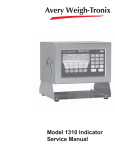
Front Panel
The front panel, shown in Figure 1, consists of the keys and display.
Plug the Model E1070 into
properly grounded socketoutlet of the correct voltage,
installed near the equipment
and easily accessible. Never
use the unit without an appropriate earthground connection.
Any computer based system
should have a separate,
grounded power circuit. We
recommend one for the
Model E1070.
See the System Block Diagram
or Main Board Assembly pages
in the technical illustrations at
the back of this manual for
wiring instructions.
Figure 1
E1070 front panel
Model E1070 Indicator Service Manual
5
The functions of the keys on the front panel are listed below.
Keys
Never press a key with anything but your finger. Damage
to the overlay may result if
sharp or rough objects are
used.
Press the TARE key to perform a tare function. Also acts as a
left arrow key when in the menu structure.
Press the SELECT key to toggle between Gross, Tare, Net,
Count, Gross Accumulator, Net Accumulator, Transaction
Counter, Piece Weight, and Peak. Dependent on the current
application. Press and hold to access the cutoffs (trips) menu.
Also acts as an up arrow key when in the menu structure.
Press the ZERO key to zero the display.
Press the PRINT key to send information to a peripheral device
through one of the Comm ports. Also acts as a down arrow key
when in the menu structure.
Press the UNITS key to scroll through the available units of
measure while in normal operating mode. Also acts as a right
arrow key when in the menu structure.
Press the F1 key to select application specific choices. Also
used to access PLU memory channels.
Press the C/CE key to clear entries.
Press the MODE key to scroll through the activated applications. Press and hold for 3-5 seconds to see the name of the
currently active application.
Press the ESC key to escape, or abort, a function or return to
normal operation mode.
Press the ENTER key to accept displayed choices.
Press and release the ON/OFF key to turn the unit on. Press
and hold the key until the unit turns off.
Use the numeric keypad to enter values.
6
Model E1070 Indicator Service Manual
There are several annunciators around the edge of the display. The illustration below explains each one.
Annunciators
Checkweighing
graph
Custom Unit
Kilogram
Motion
Pound
Gross weight
Center of zero
Accumulator,
Count
Output 3
Net weight
Output 2
Output 1
Tare weight
Preset Tare
Print
Bottom LED color when
configured for:
SCOM (SensorComm):
Red – a cell has been ghosted.
Check the ghost log.
Green – a sensorcomm error
has occurred. Print the error
log.
Off – Scale is functioning
normally.
Network 1 or 2:
Red – A network error has
occurred. Check the network
settings on the indicator and
PLC, and reboot the indicator.
Green – The network connection has been established.
Amber – The network is ready
for a connection, but no
connection has been established.
Network or
SensorComm
status
Center of Zero
Lights when weight on the scale is within the zero range
Motion
Lights during scale motion.
Gross
Lights when gross weight is displayed
Net
Lights when net weight is displayed
Tare
Lights when tare weight is displayed
Print
Lights when print format sent through serial port
OP 1
Lights when output one is activated
OP 2
Lights when output two is activated
OP 3
Lights when output three is activated
PT
Lights when preset tare is active
Network &
SensorComm
Status
This is a configurable light to show status of the Net
work 1, Network 2 or SensorComm. See note at left.
Accumulator,
Count
Lights when an accumulation occurs and while in the
count and peak applications
Custom Unit
Lights when a custom unit of measure is active
KG
Lights when kilograms is the active unit of measure
LB
Lights when pounds is the active unit of measure
Checkweigher
Lights when checkweighing application is active
Model E1070 Indicator Service Manual
7
Error Messages
The following are displays you may see if problems occur or if invalid
operations are attempted with your indicator:
Display
Description
Overrange weight. Scale is overloaded.
Underrange weight. Scale is underloaded.
The unit cannot perform a function. Displayed only while
key is held down.
Displayed while a key is pressed when attempting to
modify a sealed selection without edit privileges.
When you are in the Linearity menu item in the Service menu, you may see
the following errors:
Linear points must be done in
order from lightest weight to
heaviest.
Display
Description
Out of ascending order.
Entered value is less than 1% of scale capacity.
Entered value causes resolution of greater than 100,000
divisions.
When you are in the Span menu item in the Service menu, you may see the
following errors:
Display
Description
Entered value is greater than the configured scale
capacity.
Entered value is less than 1% of scale capacity.
Entered value causes resolution greater than 100,000
divisions
No ADC counts OR
in Overload OR
in Underload
8
Model E1070 Indicator Service Manual
All these relate to mV/V input
Menu Structure
There are several menus you use to setup or service the Model E1070. You
access the menus through the front panel. Each menu is briefly described
here. For in depth information about a menu, go to that menu's section in
this manual.
The indicator must be unsealed
to change anything in the
Service menu. Placing a
jumper on P3 in the enclosure
unseals the indicator. See
photos below.
User menu (password is 111)
The first menu covered in this manual is the User menu. This
menu allows the user to:
•
•
•
•
•
view software part numbers and revision level
view mV/V output of the scale
test the display and buttons
test the serial ports
audit the number of configurations and calibrations performed on the indicator
Service menu (password is 0701)
The second menu covered is the Service menu. In it you can:
•
•
•
•
•
•
Sealed
•
calibrate the scale system
configure the metrological functions of the indicator
enable or disable available applications
configure serial ports
test the display and buttons, test the serial ports, test the
inputs and outputs
audit the number of configurations and calibrations performed on the indicator
configure inputs and outputs and options
Supervisor menu (password is 1793)
The third menu is the Supervisor menu. This section lets you:
•
•
•
•
Unsealed
•
•
Accessing the Menus
You must begin to key in the
password within 10 seconds or
the display returns to normal
operation mode.
set time and date
clear and/or print data gathered by each application
choose special modes of operation for applications
test the display and buttons, test the serial ports, test the
inputs and outputs, analog output, pulse counter input and
networks
audit the number of configurations and calibrations performed on the indicator
configure recipes, ingredients, sample mode, over/under
values
1. Access the menus by pressing and holding the ESC key for 3-5 seconds. See note on upper left of this page.
PASS_ is displayed.
2. Key in the password of the menu you want to enter and press ENTER.
The first item in that menu is displayed.
3. Use the navigation keys shown in the box near each menu to move
through the menu.
Model E1070 Indicator Service Manual
9
User Menu
The User menu lets you test various functions of the indicator. The User
menu is shown in Figure 2.
While in a menu, the fan
graphs at the top of the display
flash as a reminder.
Figure 2
User menu flowchart
Following are specific instructions for the User menu.
1. Access the User menu by pressing and holding the ESC key for 3-5
seconds.
PASS_ is displayed.
2. Key in the User menu password (111) and press ENTER.
TEST is displayed.
3. Press the PRINT key.
ABOUT is displayed. Press the PRINT key then the UNITS key
repeatedly to view the part number and revision level for the
software found in your indicator.
Press SELECT key to return to ABOUT.
4. Press the UNITS key…
ADC is displayed. This stands for the analog to digital converter
value in mV/Vs.
5. Press the PRINT key…
The mV/V value coming into the indicator is displayed. This should
change as weight on the scale changes. Press the ZERO key to
zero the mV/V reading prior to diagnostics.
6. Press the SELECT…
ADC is displayed.
7. Press the UNITS key…
DISP is displayed. This is the display test item.
10
Model E1070 Indicator Service Manual
User Menu—(continued)
8. Press the PRINT key to perform a dynamic test of the display…
Display lights all digits and annunciators and continues to flash.
9. Press ESC key to stop the dynamic test.
10. Press the UNITS key…
BUTTON is displayed. This is the button test item.
11. Press the PRINT key to perform a button test. Each key you press will
be reflected on the display screen to confirm the button is functioning
correctly. The ESC key is excluded from this test. It is used to stop the
testing and return to the menu item
12. Press ESC key to stop the button test.
BUTTON is displayed.
13. Press the UNITS key…
SERIAL is displayed. This is the serial test item.
14. Press the PRINT key to access the serial test.
PORT1 is displayed. If you jumper the transmit and receive lines
on the serial port, as shown at left, and press the PRINT key, the
display should show PASS. If there is a problem the display will
show FAIL.
Repeat this for PORT 2.
15. Press the SELECT key to exit the serial test.
SERIAL is displayed.
16. Press the SELECT key…
TEST is displayed.
17. Press the UNITS key…
AUDIT is displayed.
18. Press the PRINT key…
CFG is displayed. This stands for the configuration audit counter.
19. Press the PRINT key to see the number of times the configuration has
been altered on this indicator.
Calibration and configuration
counters cannot be reset.
20. Press the SELECT or ENTER key…
CFG is displayed.
21. Press the UNITS key…
CAL is displayed. This stands for the calibration audit counter.
22. Press the PRINT key…
The number of times the indicator has been calibrated is displayed.
23. Press ESC twice to return to normal operation mode.
This completes the User menu.
Model E1070 Indicator Service Manual
11
Service Menu
The first level of the Service menu is shown in Figure 3. Under these items
you can do most of the configuration and calibration procedures to ready the
indicator for use. Other items are covered in the Supervisor menu section
later in this manual.
Password for the Service menu
is 0701.
While in a menu, the fan
graphs at the top of the display
flash as a reminder.
Figure 3
Service menu top level flowchart
Since the whole Service menu is quite large, it has been broken up into its
individual submenus. Each submenu is illustrated in this section followed by
specific instructions for that submenu.
CAL submenu for
analog scales
If your system is using analog scales, use the menu shown in Figure 4. If
your system is configured for SensorComm under the Service Menu>Scale>
Source menu item, follow the CAL menu, Figure 15, in the section titled CAL
submenu for SensorComm scale later in this manual.
Figure 4
CAL submenu for analog scales
1. Access the Service menu…
CAL is displayed.
ZERO
(Setting Zero Reference Point)
Press the ESC key to abort
calibration.
12
2. Press the PRINT key…
ZERO is displayed. Use this item to set the zero reference for the
indicator/scale.
Model E1070 Indicator Service Manual
Service Menu—Analog CAL submenu (continued)
3. Remove all weight from the scale and press the ENTER key…
Live weight is shown.
Press the ESC key to abort
calibration.
4. Press the ENTER key to perform the zero procedure…
BUSY is briefly displayed then the live weight which should be 0.
5. Press the ENTER key to save and return to the ZERO menu item…
ZERO is displayed.
SPAN
(Setting Span)
1. Press the UNITS key…
SPAN is displayed. Use this item to set the span for the indicator/
scale.
2. Press the PRINT key…
Current capacity is displayed.
3. Key in a new span weight value and press ENTER
or
press ENTER to accept current span weight value…
The live weight is displayed.
4. Place the correct span weight on the scale and press ENTER when
weight is stable.
BUSY is briefly displayed then the weight.
5. Press the ENTER key to accept the calibration and return to the SPAN
menu item…
SPAN is displayed.
6. Press ESC to exit to normal weighing mode (You will be prompted to
save the changes. Press ENTER to save changes)
OR go to step 1 below.
LINEAR
(Linearization)
1. Press the UNITS key…
LINEAR is displayed. Use this item to set extra calibration points.
2. Press the PRINT key…
2 is displayed. This represents cal point 2.
3. Press the ENTER key to set this calibration point…
Linear points must be done in
order from lightest weight to
heaviest.
A numeric value is displayed.
4. Key in a weight value for this calibration point and press the ENTER key.
Live weight on the scale is displayed.
5. Place the test weight for this calibration on the scale and press ENTER.
Busy is briefly displayed and then 2.
Model E1070 Indicator Service Manual
13
Service Menu—Analog CAL submenu (continued)
6. Press the UNITS key to move to the next calibration point…
3 is displayed.
7. Repeat steps 3-6 for cal point 3 and 4.
When you are done 4 will be displayed.
8a. Press the SELECT key to return to the LINEAR menu item.
OR
8b. Press the ESC key to return to normal operating mode. You will be
prompted to save the changes. Press ENTER to save them or the ESC
key to abort the save process and return to normal operating mode
without saving calibration.
INPUT
(Input Calibration)
Use this item to hand enter zero and span calibration factors. This is useful
if one indicator fails and is replaced with another but no test weights are
available. Linearization factors cannot be entered.
1. Press the UNITS key…
To use this item you must have
recorded the calibration factors
from your previously installed
E1070 indicator.
Calibration factors can be
viewed under CAL>INPUT or
you can print them out using
the CAL>PRINT menu item.
INPUT is displayed.
2. Press the PRINT key…
ZERO is displayed.
3. Press the PRINT key…
A numeric value is displayed.
4. Key in the zero factor from your previous indicator and press the ENTER
key.
BUSY is briefly displayed, then ZERO.
5. Press the UNITS key…
SPAN is displayed.
6. Press the PRINT key…
A numeric value is displayed.
7. Key in the span factor from your previous indicator and press the
ENTER key…
A span weight is displayed.
8. Accept the span weight by pressing the ENTER key or key in a new
span weight and press the ENTER key to accept it…
BUSY is briefly displayed, then SPAN.
9. Press the SELECT key to return to the INPUT menu item.
14
Model E1070 Indicator Service Manual
Service Menu—Analog CAL submenu (continued)
DISP
(Live Weight Display)
1. Press the UNITS key…
DISP is displayed. Use this item to view the live weight on the
scale without exiting the Service menu.
2. Press the PRINT key…
The live weight is displayed.
3a. Press the SELECT key…
DISP. is displayed.
OR
3b. Press the SELECT key to move to the top of the Service menu…
CAL is displayed.
PRINT
(Print a Calibration Report)
1. Press the UNITS key…
PRINT is displayed. This item lets you print a calibration report.
The information printed can be very useful in case of service
issues later.
2. Press the PRINT key…
PORT 1 is displayed. The other choice is PORT 2. This allows you
to choose a port through which the calibration report is printed.
3. Toggle between the choices using the TARE or UNITS key and press
ENTER when your choice is displayed…
The report is printed and the display returns to PRINT.
4a. Press the SELECT key to return to the CAL item of the Service menu
and continue with the Service menu instructions in the next section
OR
4b. Press the ESC key to return to normal operation mode.
SAVE is displayed.
5. Press the ENTER key to save changes or press the ESC key to exit the
menu without saving.
This completes the CAL section of the Service menu for analog scales. If
you have a SensorComm system, see the section SensorComm Hardware
Configuration and Calibration for calibration and configuration information.
The next Service menu item, SCALE, is covered in the SCALE Submenu
section.
Model E1070 Indicator Service Manual
15
SCALE submenu
Use this section of the Service menu for scale configuration. Figure 5 shows
the flowchart of this menu item. Follow the directions and explanations
below to set up these items.
Figure 5
Scale submenu flowchart
1. Access the Service menu…
CAL is displayed.
2. Press the UNITS key…
SCALE is displayed.
Source
(Analog or SensorComm)
Calibration instructions for
Analog scales are in the
section—CAL submenu for
analog scales
Calibration instructions for
SensorComm scales are in the
section—CAL submenu for
SensorComm scales
16
3. Press the PRINT key…
SOURCE is displayed. Use this item to choose between an
analog or SensorComm based system.
4. Press the PRINT key…
The current setting is displayed.
5. Toggle between the Analog and Scom (North America only) choices
using the TARE or UNITS key. When your choice is displayed press the
ENTER key…
SOURCE is displayed.
Model E1070 Indicator Service Manual
Service Menu—SCALE submenu (continued)
CAP.
(Capacity)
1. Press the UNITS key…
CAP. is displayed. Use this item to set the capacity for the scale.
2. Press the PRINT key…
The current capacity value is shown.
3. Press ENTER to accept this value or key in a new capacity and press
ENTER…
CAP. is displayed.
DIV.
(Division)
This item and the next one, DP.POS., set the division size.
1. Press the UNITS key…
DIV. is displayed. This stands for the division value of your
displayed weight.
2. Press the PRINT key…
The current division value is shown.
3. Scroll through the choices by using the TARE or UNITS key.
Pick from the following values; 1, 2, 5, 10, 20, 50, 100, 200, 500,
1/2, 2/5, 5/10, 10/20, 20/50.
The fraction choices are for use as dual range divisions. The
first number is the division value for the first half of the
capacity and the second number is the division value for the
2nd half of the capacity.
All of these capacities function in conjunction with the decimal
place position. For example, if you choose a division value of 5
and a decimal position of 12345.6, your division size will be .5.
4. When your choice is displayed, press ENTER.
DIV. is displayed.
DP.POS.
(Decimal point position)
Use this item to set the decimal point position in the displayed weight.
1. Press the UNITS key…
DP.POS. is displayed. This stands for decimal point position.
2. Press the PRINT key…
The current decimal point position is shown. Choices available
are; 123456, 12345.6, 1234.56, 123.456, 12.3456 and 1.23456.
3. Scroll through the choices by using the TARE or UNITS key. When your
choice is displayed, press ENTER.
DP.POS. is displayed.
Model E1070 Indicator Service Manual
17
Service Menu—SCALE submenu (continued)
UNITS
(Unit of measure)
You can have up to three units of measure active. They are lbs, kgs, or a
custom unit of measure.
Follow these steps:
1. Press the UNITS key…
UNITS is displayed.
2. Press the PRINT key…
LB is displayed.
3. Turn each unit of measure ON or OFF by scrolling to the unit by using
the TARE or UNITS key and pressing the PRINT key…
If your new custom unit is
larger than one CAL UNIT,
then you key in how many CAL
UNITS make up 1 new custom
unit. For example 1 TON =
2000 pounds so with pounds
selected as our CAL UNIT we
would key in 2000 for the
multiplier.
one cal unit
number of custom units
If your new custom unit is
smaller than one CAL UNIT,
then you divide one cal unit by
the number of custom units it
takes to make up a single CAL
UNIT. Multipliers are limited to
a total of seven digits by the
display.
Example #1:
16 ounces = 1 pound.
Do the math:
(one cal unit / number of
custom units = the multiplier)
1/16=0.0625
So with pounds selected as our
CAL UNIT we would key in
0.0625 for the multiplier.
Example #2:
1000 Grams = 1 KG.
Do the math:
(one cal unit / number of
custom units = the multiplier)
1/1000=0.001
So with KG selected as our
CAL UNIT we would key in
0.001 for the multiplier.
18
The current state of the unit is displayed.
4. For lbs and kgs, toggle between ON or OFF by using the TARE or
UNITS key. Press ENTER when your choice is displayed…
Display returns to LBS or 1000G.
If you choose to activate the custom unit of measure you will be
prompted for a multiplier which defines the custom unit in relation to the
calibration unit of measure and a string entry for a unit label. See note at
left. Key the multiplier in and press ENTER to enter the value.
String entry screen is displayed. Edit the string (up to seven
characters long) to create a name for the custom unit of measure.
For directions on string editing, see the section Extra Info: Print
Format Editing. String editing is covered in that section.
5. Press ENTER key to accept the string values …
CUST. is displayed.
6. Press the UNITS key…
C-UNIT is displayed. This stands for calibration unit. Use this item
to set the calibration unit of measure; lbs or kgs (1000 G).
7. Press the PRINT key…
Current calibration unit is displayed. Choices are lb or 1000G.
8. Toggle between the choices by using the TARE or UNITS key and press
the ENTER key to accept the choice…
C-UNIT is displayed.
9. Press the SELECT key…
UNITS is displayed.
Model E1070 Indicator Service Manual
Service Menu—SCALE submenu (continued)
STABLE
(Stability window)
Use this item to define the stability window in terms of ±X divisions for a
period of time, in seconds, you set.
1. Press the UNITS key…
STABLE is displayed.
2. Press the PRINT key…
DIV. is displayed.
3. Press the PRINT key…
The current division size is displayed. If a weight changes less
than this number of divisions in the time period you select in the
next steps, the motion light turns off and the weight is considered
stable.
You choices are 0.25, 0.5, 1, 3 and CUST. (custom)
4. Scroll through the choices by using the TARE or UNITS key and press
the ENTER key to accept the displayed choice…
DIV. is displayed for any choice other than CUST. If you pick
CUST. go to step 4a. If you picked any other division size, go to
step 5.
4a. If you pick a custom window size you are shown the current value. Key
in a custom size and press ENTER to save the custom value…
DIV. is displayed.
5. Press the UNITS key…
SEC. is displayed. Use this item to set the time window for stability
determination.
6. Press the PRINT key…
The current time window size is displayed. If a weight changes
less than this number of divisions, set above, in the time period
you select, the motion light turns off and the weight is considered
stable.
You choices are 1-10 seconds and CUST. (custom)
7. Scroll through the choices by using the TARE or UNITS key and press
the ENTER key to accept the displayed choice…
SEC. is displayed for any choice other than CUST. If you pick
CUST. go to step 7a. If you picked any other division size, got to
step 8.
If CUSTOM is selected, only
fractional time between 0-10
seconds can be entered.
7a. If you pick a custom time you are shown the current value. Key in a
custom time and press ENTER to save the custom value…
Example: 1.5 seconds, 2.25
seconds, etc.
8. Press the SELECT key…
SEC. is displayed.
STABLE is displayed.
Model E1070 Indicator Service Manual
19
Service Menu—SCALE submenu (continued)
AZT
(Automatic Zero Tracking)
Use this item to set the division size and seconds. The division size you pick
defines a range above and below zero. When scale weight is inside this
range for the number of seconds you picked, ½ of the weight will be zeroed.
The indicator will repeat removing ½ the weight every X seconds. X being
the number of seconds you have picked.
1. Press the UNITS key…
AZT is displayed.
2. Press the PRINT key…
DIV. is displayed.
3. Press the PRINT key…
The current division size is displayed.
You choices are 0.25, 0.5, 1, 3 and CUST. (custom)
For the purpose of explaining
all items in the menus, these
instructions show an orderly
accessing of each part of the
menu. You do not have to
access an item in this way.
Use the navigation buttons to
skip around to the item you
want to change or view.
4. Scroll through the choices by using the TARE or UNITS key and press
the ENTER key to accept the displayed choice…
DIV. is displayed for any choice other than CUST. If you pick
CUST. go to step 4a. If you picked any other division size, got to
step 5.
4a. If you pick a custom window size you are shown the current value. Key
in a custom size and press ENTER to save the custom value…
DIV. is displayed.
5. Press the UNITS key…
SEC. is displayed. Use this item to set the time window for stability
determination.
6. Press the PRINT key…
The current time window size is displayed.
You choices are 1-10 seconds and CUST. (custom)
7. Scroll through the choices by using the TARE or UNITS key and press
the ENTER key to accept the displayed choice…
SEC. is displayed for any choice other than CUST. If you pick
CUST. go to step 7a. If you picked any other division size, got to
step 8.
If CUSTOM is selected, only
fractional time between 0-10
seconds can be entered.
7a. If you pick a custom time you are shown the current value. Key in a
custom time and press ENTER to save the custom value…
SEC. is displayed.
8. Press the SELECT key…
Example: 1.5 seconds, 2.25
seconds, etc.
20
AZT is displayed.
Model E1070 Indicator Service Manual
Service Menu—SCALE submenu (continued)
TARE
(Tare parameters)
Use this item to set the tare function parameters;
Clear tare
If you enable (ON) this item, the tare will be automatically cleared when the weight falls below the value set
under the G-Band menu item.
Pushbutton tare
If you enable this item (ON), you can use the TARE key
to tare a weight from the scale. If you disable (OFF) this
item, you cannot tare using the TARE key.
Enter tare
If you enable this item (ON), you can enter a known tare
weight by keying in a weight and pressing the TARE
key.
Follow these steps to set the tare item:
1. Press the UNITS key…
TARE is displayed.
2. Press the PRINT key…
CLEAR is displayed.
3. Press the PRINT key…
ON or OFF is displayed. Use this to enable or disable the Clear
tare item.
4. Toggle between the choices by using the TARE or UNITS key and press
the ENTER key to accept the displayed choice…
CLEAR is displayed.
5. Press the UNITS key…
P.B. is displayed.
6. Press the PRINT key…
ON or OFF is displayed. Use this to enable or disable the Pushbutton tare item.
7. Toggle between the choices by using the TARE or UNITS key and press
the ENTER key to accept the displayed choice…
P.B. is displayed.
8. Press the UNITS key…
ENTER is displayed.
9. Press the PRINT key…
ON or OFF is displayed. Use this to enable or disable the Enter
tare item.
10. Toggle between the choices by using the TARE or UNITS key and press
the ENTER key to accept the displayed choice…
ENTER is displayed.
11. Press the SELECT key…
TARE is displayed.
Model E1070 Indicator Service Manual
21
UPDATE
(Display Update Rate)
Use this item to set the number of display updates/second. Choices are 1, 2,
5 and 10 times/second. 10 is the default value.
1. Press the UNITS key…
UPDATE is displayed.
2. Press the PRINT key…
Current update rate is displayed. Choices are 1, 2, 5 and 10 times
per second.
3. Scroll through the choices by using the TARE or UNITS key and press
the ENTER key to accept the displayed choice. .
UPDATE is displayed.
The AVG and FILTER menu items discussed below are best explained by
an example of how the filtering works on this indicator.
Filtering is used to counteract vibration of the scale. The A-D weight conversion happens 100 times per second in the E1070. AVG is the number of
conversions you want to average. For example, if you pick 50, the unit will
average the weight values from the last 50 conversions or ½ second and
uses that value for displayed data.
If you turn the filtering on you need to set the Constant. Typical values are
between 1-10. Set the number low for small vibration problems and higher
for more dampening effect.
The purpose of the Threshold is so the indicator will respond quickly to large
weight changes. Threshold is the amount of weight change, in calibration
units, beyond which the filter will be temporarily disabled. For example, if you
set this to 10 lbs, a weight change over 10 pounds occurring during the
sample time (½ sec. in our example) will disable the filter until the weight
change during the sample time drops below 10 lbs.
AVG
(Averaging of A-D)
AVG is the number of conversions you want to average for the weight that is
displayed. 20 is the default value.
1. Press the UNITS key…
AVG is displayed.
2. Press the PRINT key…
The current value is displayed.
3. Press ENTER to accept the current value
OR
Key in a new value, between 0 and 512, and press ENTER to accept
it…
BUSY is briefly displayed, then AVG.
22
Model E1070 Indicator Service Manual
Service Menu—SCALE submenu (continued)
FILTER
(Noise filtering)
Use this item to set the noise filtering parameters.
1. Press the UNITS key…
FILTER is displayed.
2. Press the PRINT key…
Current setting is displayed. Choices are OFF, FLTR 1 and FLTR
2.
Off means no filtering. FLTR 1 filtering is slower response to
weight in a longer time period with improved accuracy. FLTR 2
filtering is faster response to weight in a short time.
3. Scroll through the choices by using the TARE or UNITS key and press
the ENTER key to accept the displayed choice…
If you choose OFF, display returns to FILTER. You can continue
to the next menu item (d.Point).
If you choose FLTR 1 or 2, continue to step 4.
4. With FLTR 1 or FLTR 2 displayed, press the PRINT key…
CONST is displayed. This stands for Constant and is one of two
filtering parameters you need to set.
5. Press the PRINT key…
Current value is displayed. For the Constant value you can pick a
value between 1 and 10. Set the number low for small vibration
problems and use a higher setting for more dampening effect.
6. Scroll through the choices by using the TARE or UNITS key and press
the ENTER key to accept the displayed choice…
CONST is displayed.
Model E1070 Indicator Service Manual
23
Service Menu—SCALE submenu (continued)
7. Press the UNITS key…
THRESH is displayed. This stands for Threshold, the 2nd filtering
parameter.
A THRESHOLD setting of 0 will
turn filtering on all the time.
Threshold causes the indicator to respond quickly to large weight
changes. Threshold is the amount of weight change, in calibration
units, beyond which the filtering will be temporarily disabled. For
example, if you set this to 10 lbs, a weight change over 10 pounds
occurring during the sample time will disable the filtering until the
weight change during the sample time drops below 10 lbs.
8. Press the PRINT key…
Current value is displayed.
9. Key in a value. Press the ENTER key…
THRESH is displayed.
10. Press the SELECT key…
FLTR 1 or FLTR 2 is displayed.
11. Press the SELECT key…
BUSY is displayed briefly then FILTER. Whichever filter you set
up becomes the active filter for the indicator.
D.POINT
(Decimal point)
Use this item to toggle between decimal point and a comma for the fraction
delimiter for the display. For example, if you pick DEC the display will show
10.5. If you pick COMMA, the display will show 10,5.
1. Press the UNITS key…
D.POINT is displayed.
Example:
decimal = 000.00
comma = 000,00
2. Press the PRINT key…
The current setting is displayed.
3. Toggle between the choices, DEC or COMMA, by using the TARE or
UNITS key and press the ENTER key to accept the choice…
D.POINT is displayed.
24
Model E1070 Indicator Service Manual
Service Menu—SCALE submenu (continued)
0-RANGE
(Zero range)
Use this item to key in a percentage of capacity, within which the ZERO key
will zero the scale.
1. Press the UNITS key…
0-RNGE is displayed.
2. Press the PRINT key…
The current setting is displayed. This is a percentage of capacity.
3. Key in a new value and press ENTER to accept the value
OR
Press the ENTER key to accept the displayed choice…
0-RNGE is displayed.
O-CAP.
(Over capacity range)
Use this item to set the point at which over range (upper) dashes are
displayed. You can choose between 105% of capacity or 9 divisions over
capacity.
1. Press the UNITS key…
O-CAP. is displayed.
2. Press the PRINT key…
The current setting is displayed.
3. Toggle between the choices by using the TARE or UNITS key and press
the ENTER key to accept the choice…
O-CAP. is displayed.
G-BAND
(Gross zero band)
Use this item to set the gross zero band. This is a parameter used to trigger
the tare clear function covered previously in the Scale submenu.
You can enter values between 0 and 100 divisions.
1. Press the UNITS key…
G-BAND is displayed.
2. Press the PRINT key…
The current setting is displayed.
3. Key in a new value and press ENTER to accept the value
OR
Press the ENTER key to accept the displayed choice…
G-BAND is displayed.
Model E1070 Indicator Service Manual
25
Service Menu—SCALE submenu (continued)
C-ZERO
(Center of zero window)
This item is to set the window size for the center-of-zero annunciator. You
can choose between ±¼ and ±½ division. When the weight falls within the
window size, the center-of-zero annunciator lights.
1. Press the UNITS key…
C-ZERO is displayed.
2. Press the PRINT key…
The current setting is displayed.
3. Toggle between the choices by using the TARE or UNITS key and press
the ENTER key to accept the choice…
C-ZERO is displayed.
SERIAL
(Serial number entry)
Use this item to enter the serial number for your indicator. This value is used
in some serial outputs and reports for record keeping purposes.
1. Press the UNITS key…
SERIAL is displayed.
2. Press the PRINT key…
The serial number of your
indicator can be found on the
affixed tag on the outside of the
indicator case.
The current setting is displayed.
3. Key in the serial number of your indicator and press ENTER to accept
the value
OR
Press the ENTER key to accept the displayed choice…
SERIAL is displayed.
4. This completes the SCALE portion of the Service menu. You can exit to
normal weighing mode or continue on to the next menu item, APP. To
exit, go to step 5. To continue, go to step 7.
5. Press the ESC key.
SAVE is displayed.
6. Press ENTER to save the changes you’ve made
OR
Press ESC to abort the changes…
Display returns to normal operation mode.
7. Press the SELECT key…
SCALE is displayed.
8. Press the UNITS key…
APP is displayed.
26
Model E1070 Indicator Service Manual
APP submenu
In normal operating mode,
press the MODE key to
change from one enabled
application to the next.
The next section of the Service menu is the APP submenu. See Figure 6.
This menu lets you choose the default parameters for your location and also
lets you enable or disable each application available in this indicator. Under
each enabled application you can edit the default print format (#0) and
choose which formats (#0-10) to print and through which port. You can
configure the extra formats (#1-10) in the SERIAL submenu item in the
Service menu.
*
* Print format ‘0’ is used for this string. Strings
#1-10 are located under the Serial submenu.
Figure 6
APP (applications) submenu
Follow these steps to access each item in the APP menu and to understand
what they do and how to set them:
Applications are enabled in the
Service menu but you do each
application’s setup in the
Supervisor menu.
1. Access the Service menu…
CAL is displayed.
2. Press the UNITS key twice…
APP is displayed.
SITE
(Setting site defaults)
3. Press the PRINT key…
SITE is displayed.
Use this item to choose your instrument location; NA (North
America), EU (Europe). Choosing the correct one will set defaults
to your location’s requirements.
Master Reset
If you change the site setting
and save the change, then
change it back to the original
site and save, the defaults will
be reset to factory defaults.
This will not affect calibration,
print formats or recipes.
4. Press the PRINT key…
Current setting is displayed.
5. Toggle between the choices by using the TARE or UNITS key and
press the ENTER key to accept the displayed choice. .
SITE is displayed.
See note at left.
Model E1070 Indicator Service Manual
27
Service Menu—APP submenu (continued)
ACC
(Accumulator application)
1. Press the UNITS key…
ACC. is displayed. This stands for the Accumulator application.
2. Press the PRINT key…
ON or OFF is displayed, depending on the current setting.
3. Press the SELECT key to back out of this item without enabling it
OR
Press the ENTER key to enable this application…
STRING is displayed. This is where you can choose a port to print
through and view and/or edit the default print format.
If you choose TCPIP1 or
SMTP1, Net 1 under
OPTION>NETS must be set to
E-net-1 or E-net-4.
4. With STRING displayed, press the PRINT key…
If you choose TCPIP2 or
SMTP2, Net 2 under
OPTION>NETS must be set to
E-net-1 or E-net-4.
5. Toggle between the choices by using the TARE or UNITS key and press
ENTER to accept the displayed choice. .
The current port setting appears. Choices are Port 1, Port 2,
TCPIP1, TCPIP2, SMTP 1 or SMTP 2. See note at left.
A string of numbers appears. See note at left and example below.
There are default print
formats for each application.
These are all given a format
number = 0.
These numbers represent the default print format in numbered
sequence of hexadecimal commands. Each hexadecimal command represents one printing character or print command. These
numbers allow you to customize the print output of the indicator.
See the Extra Info: Print Format Editing section for full explanation
and instruction on modifying a print format.
You can exit the Service menu
at any time by pressing the
ESC key. When SAVE appears
on screen you can press ESC
to lose any changes or press
ENTER to save the changes
and return to normal operating
mode.
When you key in a 1 followed
by a 0, the indicator is smart
enough to know this is a 10 not
separate 1 and 0 formats.
Always enter format numbers
in ascending order.
6. Modify the print format as needed and press the ENTER key when
finished. .
STRING is displayed.
7. Press the UNITS key…
P-FT is displayed. This stands for print format. You can send one
or more print formats through a port each time the PRINT key is
pressed. This is the item you use to define which formats get
printed.
8. Press the PRINT key…
Numeric entry screen is displayed.
9. Key in the format numbers you want printed. See note at left. For
example, to print formats 0, 1, and 4, key in 014 and press the ENTER
key. To print the 0, 1, 3, and 10 formats, key in 01310 and press the
ENTER key…
P-FT is displayed.
28
Model E1070 Indicator Service Manual
Service Menu—APP submenu (continued)
10. Press the SELECT key…
ACC. is displayed.
11. Press the UNITS key…
BATCH is displayed.
BATCH
(Batch application)
1. From previous step 11, press the PRINT key…
Repeat steps 2-9 from the ACC (Accumulator application) section
to set up the Batch application.
2. Press the SELECT key…
In normal operating mode,
press the MODE key to
change from one enabled
application to the next.
TARGET
(Checkweighing application)
BATCH is displayed.
3. Press the UNITS key…
TARGET is displayed.
1. Press the PRINT key…
Repeat steps 2-9 from the ACC (Accumulator application) section
to set up the Target application.
2. Press the SELECT key…
TARGET is displayed.
3. Press the UNITS key…
COUNT is displayed.
COUNT
(Counting application)
You can exit the Service menu
at any time by pressing the
ESC key. When SAVE appears
on screen you can press ESC
to lose any changes or press
ENTER to save the changes
and return to normal operating
mode.
TOP
(Peak hold application)
1. Press the PRINT key…
Repeat steps 2-9 from the ACC (Accumulator application) section
to set up the Target application.
2. Press the SELECT key…
COUNT is displayed.
3. Press the UNITS key…
TOP is displayed.
1. Press the PRINT key…
Repeat steps 2-9 from the ACC (Accumulator application) section
to set up the Target application.
2. Press the SELECT key…
TOP is displayed.
3. Press the UNITS key…
R-DISP is displayed.
Model E1070 Indicator Service Manual
29
Service Menu—APP submenu (continued)
R-DISP
(Remote Display)
1. From previous step 3 in section TOP (Peak hold application), press the
UNITS key…
R-DISP is displayed. This stands for remote display. Use this item
to set up your indicator as a remote display for another indicator.
2. Press the PRINT key…
ON or OFF is displayed, depending on the current setting.
3. Press the PRINT key…
In normal operating mode,
press the MODE key to
change from one enabled
application to the next.
PORT is displayed. Use this item to select which port the master
indicator will use to communicate with this remote display.
4. Press the PRINT key…
The current port selection is displayed.
5. Toggle between the choices by using the TARE or UNITS key. Press
the ENTER key when your choice is displayed…
PORT is displayed.
6. Press the UNITS key…
MODE is displayed. Use this item to configure how the remote will
operate.
7. Press the PRINT key…
Current mode value is displayed.
MODE 1
Indicator displays gross annunciator, weight and units
annunciator. This is an emulation of the RD4100
remote display.
MODE 2
Indicator does the same thing as Mode 1 plus annunciators reflect the main display status.
MODE 3
Indicator acts as Mode 1 plus the following keys work;
TARE, SELECT, ZERO, PRINT and UNITS.
MODE 4
Indicator acts the same as in Mode 3 plus all the
annunciators reflect the main display status
8. Scroll through the choices using the TARE or UNITS key. When your
choice is displayed, press the ENTER key…
MODE is displayed.
30
Model E1070 Indicator Service Manual
Service Menu—APP submenu (continued)
GENRAL
(General Weighing Application)
1. Press the SELECT key repeatedly until…
R-DISP is displayed.
2. Press the UNITS key…
GENRAL is displayed. This is the general weighing application.
Repeat steps 2-9 from the ACC (Accumulator application) section
to set up the General weighing application. This is the default
application for the indicator upon arrival from the factory.
3. Press the SELECT key…
GENRAL is displayed.
4. Press the ESC key to exit the Service menu…
SAVE is displayed.
5. Press ENTER to save your changes or press ESC to abort any changes
made in the Service menu…
BUSY flashes until the indicator returns to normal operation
mode.
This completes the APP menu.
Model E1070 Indicator Service Manual
31
Extra Info:
Print Format Editing
The first three numbers are the sequence of the print commands.
The last two characters are the hexadecimal number for the print
command.
Use the keys as described in Figure 7 to scroll through the sequence and change the hex. character value.
Figure 7
Key legend for hex editing
FF is the hex. value for End of
String (EOS). When this value
is entered in a print format, any
values beyond this in the
sequence are ignored and the
display will wrap back to the
001 item.
You can overwrite the FF value
and use up to the maximum
string length if so desired. In
the E1070 the maximum
sequence length is 256.
However, the last character in
the print format must be FF. Be
sure to add the FF character if
it is removed.
32
TARE keySELECT key ZERO keyPRINT keyUNITS keyENTER keyON/OFF key-
moves to the previous sequence number
increments hex character up
Toggles between first and second hex digit
decrements hex character down
moves right through the print string
Accepts print string and exits edit mode
A short key press inserts a new character in front
of the displayed character. Press and hold to
delete the currently displayed hex character.
Hex values of 7F (127 decimal) and below are printable characters
and can be seen in Table 1. Hex values from 80 (128 decimal) to
FF (255 decimal) is for print command tokens and can be seen in
Table 2. See note at left.
The default print formats for each application is shown on the next
page.
Model E1070 Indicator Service Manual
Print Formats 1-8 are for the Zebra Thermal printer. See examples on the
following pages.
Print Formats 9-15 are for a standard ASCII characters for use with dot
matrix printer.
Print Formats 9 & 10
G 123456 lb
{ACT}{DSP}{UN}<CR><LF>{EOS}
Accumulator (Print Format 11), Batching (12) and Checkweigher (13)
all use the following:
G 123456 lb
{ACT}{DSP}{UN}<CR><LF>{EOS}
Counting, Print Format 14
Piece Count:
48
Piece Count: {CNT}<CR><LF>{EOS}
Peak Print Format 15
123456 lb
{PWT} {UN}<CR><LF>{EOS}
Remote Display Print Format 16
G 123456 lb
{ACT} {DSP} {UN}<CR><LF>{EOS}
The following are the default print formats are for the corresponding “Mode”
setting in the serial port configuration menu.
17 Port 1 Enquire (HEX05)
18 Port 1 Broadcast
19 Port 1 RD4100
20 Port 2 Enquire (HEX05)
21 Port 2 Broadcast
22 Port 2 Remote display
G
123456 lb
{ACT} {DSP} {UN}<CR><LF>{EOS}
Model E1070 Indicator Service Manual
33
Thermal Labels Print
Formats
Format 1, 2 & 3
Time
Date
G
Gross Weight
T
Tare Value
N
Net Weight
Format 1 label 1.25” Wide x 1.00” Long
Format 2 label 2.50” Wide x 4.00” Long
Format 3 label 4.00” Wide x 6.00” Long
Print Format 4, same as above with barcode.
Label Size:
2.50” Wide
4.00” Long
Print Formats 5, 6 & 7
Time
Date
PLU Totals Information
Gross Total Accumulator
Format 5 label 1.25” Wide x 1.00” Long
Format 6 label 2.50” Wide x 4.00” Long
Format 7 label 4.00” Wide x 6.00” Long
Print Format 8, same as above with barcode.
Label Size
2.50” Wide
4.00” Long
34
Model E1070 Indicator Service Manual
Table 1
Printable characters chart
Model E1070 Indicator Service Manual
35
Table 2
Printing commands chart
Dec
128
HEX
80
Token
GWT(,n)
Application
Gross Weight [1]
Group
Weight
129
81
NWT(,n)
Net Weight [1]
Weight
131
83
SAT(,n)
Semi-Auto Tare [1]
Weight
132
135
136
84
87
88
UN
ID
TIM,x
Units
Scale Serial Number
Time
Weight
Misc
Time
137
89
DAT,x
Date
Date
138
8A
TTV,n
Target Value
Trip
142
8E
CLA(,n)
143
8F
CHA(,n)
144
90
RAV,n
145
91
RTV,n
Active Recipe
Ingredient x ‘Target’ value
Recipe
146
92
RPV,n
Active Recipe
Ingredient x ‘Preact’ value
Recipe
147
93
RIU,n
Active Recipe
Ingredient x units
Recipe
148
149
151
153
155
94
95
97
99
9B
PCE
CNT
GTO
STO
PLU
Piece Weight
Current Count Value
Gross Accumulator
Net Accumulator
PLU NumberData
Count
Count
Weight
Weight
PLU
36
Checkweigher
Checkweight
‘Low Accept’ value [1]
Checkweigher
Checkweight
‘High Accept’ value [1]
Active Recipe
Recipe
Ingredient x ‘Actual’ value
Model E1070 Indicator Service Manual
Parameter
OPTIONAL, (ASCII)
Range: (‘2’-‘9’), Indicator Default: ‘6’
OPTIONAL, (ASCII)
Range: (‘2’-‘9’), Indicator Default: ‘6’
OPTIONAL, (ASCII)
Range: (‘2’-‘9’), Indicator Default: ‘6’
MANDATORY (DECIMAL)
Range: (0-2), Editor Default:1
0= Format as set/active in indicator
1= hh:mm
2= hh:mm AM/PM
MANDATORY, (DECIMAL)
Range: (0-4), Editor Default:1
0= Format as set/active in indicator
1= MM/DD/YY
2= MM/DD/YYYY
3= DD/MM/YY
4= DD/MM/YYYY
MANDATORY, (HEX #s)
Range: (‘31’-‘33’), Editor Default: ‘1’
For target weights
OPTIONAL, (ASCII)
Range: (‘2’-‘9’), Indicator Default: ‘6’
OPTIONAL, (ASCII)
Range: (‘2’-‘9’), Indicator Default: ‘6’
MANDATORY, (HEX #s)
Range: (‘31’-‘38’), Editor Default: ‘1’
For target weights in recipe
MANDATORY, (HEX #s)
Range: (‘31’-‘38’), Editor Default: ‘1’
For preact values in recipe
MANDATORY, (HEX #s)
Range: (‘31’-‘38’), Editor Default: ‘1’
For target weights in recipe
MANDATORY, (HEX #s)
Range: (‘31’-‘38’), Editor Default: ‘1’
For ingredient units (lb or kg for weight
based ingredients; sec for time based
ingredients; cnts or gallons for pulse
counter based ingredients). To be
printed after the target or actual ingredient value.
Dec
156
162
170
173
178
184
188
189
190
200
HEX
9C
A2
AA
AD
B2
B8
BC
BD
BE
C8
Token
DES
DIS
VER
WST
PUP
PUT
PCT
LST
LGT
DSP(,n)
215
216
D7
D8
NULL
ACT
242
253
F2
FD
PWT
HEX,xx
254
FE
TEX
255
FF
EOS
Application
Group
PLU ID
PLU
Remote Display Status
Miscellaneous
Software Version Number
Miscellaneous
Weight Steady
Weight
Tare associated with the PLU
PLU
PLU Totals Information
PLU
PLU Count Total
PLU
Net Accumulator
PLU
Gross Accumulator
PLU
Print the displayed weight
Weight
Null Token
Print the active value (‘G’ for
gross, ‘N’ for net, ‘T’ for tare)
Peak Hold Weight value
Following number will be
transmitted by value. Also,
use this selection to
transmit a NUL as well.
Reserved for future use
as a ‘token extender’
End of String
Strings
Weight
Weight
Hex-Codes
Parameter
OPTIONAL, (ASCII)
Range: (‘2’-‘9’), Indicator Default: ‘6’
MANDATORY, (ASCII-HEX)
Range: (00 – FF), Editor Default: 00
----String
Notes:
These tokens can be optionally followed by an ASCII 2 to 9 to specify the number of weight digits (including
decimal point). If no specifier is given it defaults to 6 digits (+ decimal point) (equivalent to ASCII 6).
Further, parameter values may be ASCII digits (i.e. range ‘0’ thru ‘9’) or DECIMAL values (i.e. range 0 thru 255). In
all cases, parameters consume one byte. In the term/token table parameters are indicated as follows:
Optional, (ASCII)
(,n)
Optional, (Decimal)
(,x)
Mandatory, (ASCII)
,n
Mandatory, (Decimal) ,x
Model E1070 Indicator Service Manual
37
The next section of the Service menu is the SERIAL submenu. See Figure
8. This menu lets you choose the configure the serial ports and create
custom print formats #1-10.
SERIAL submenu
Figure 8
SERIAL (serial communication) submenu
The default serial port parameters are 9600 baud, 8 databits, no parity and 1 stop bit.
Stop bits for the serial
communication are preset to
1 stop bit. This is not configurable.
Follow these steps to access each item in the SERIAL menu and to understand what they do and how to set them:
1. Access the Service menu…
CAL is displayed.
2. Press the UNITS key repeatedly until…
SERIAL is displayed.
3. Press the PRINT key…
PORT 1 is displayed.
Port 1 or Port 2
4. Scroll through the other choices, PORT 2 and STRING, by using the
TARE or UNITS key and press the ENTER key to accept the displayed
choice. If you choose PORT 1 or PORT 2, continue with the rest of this
step. If you choose STRING, go to the section STRING (Custom print
formats).
All the port configuration items are identical for Port 1 and Port 2
except port 1 has two additional TYPE selections (RS-485 and
485HD). Use the following steps to configure each port.
BAUD is displayed.
Use this item to set the baud rate.
38
Model E1070 Indicator Service Manual
Service Menu—SERIAL submenu (continued)
BAUD
(Baud rate)
5. Press the PRINT key …
Current baud rate is displayed. Choices are from 300 to 115,200.
Default is 9600.
6. Scroll the choices by using the TARE or UNITS key and press the
ENTER key to accept the displayed choice. .
BAUD is displayed.
D-BITS
(Data bits)
1. Press the UNITS key…
D-BITS is displayed. Use this item to set the data bits value.
2. Press the PRINT key…
7 or 8 is displayed.
3. Toggle between the choices by using the TARE or UNITS key and
press the ENTER key to accept the displayed choice. .
D-BITS is displayed.
PARITY
(Parity setting)
1. Press the UNITS key…
PARITY is displayed. Use this item to set parity.
2. Press the PRINT key…
NONE, ODD or EVEN is displayed.
3. Scroll through the choices by using the TARE or UNITS key and press
the ENTER key to accept the displayed choice. .
PARITY is displayed.
C-TROL
(Handshakecontrol)
1. Press the UNITS key…
C-TROL is displayed. Use this item to set parity. Use this item to
set the handshake control.
2. Press the PRINT key…
NONE, RTS or SOFT (Xon/Xoff) is displayed.
3. Scroll through the choices by using the TARE or UNITS key and press
the ENTER key to accept the displayed choice. .
C-TROL is displayed.
Model E1070 Indicator Service Manual
39
Service Menu—SERIAL submenu (continued)
TYPE
(Serial port mode )
1. Press the UNITS key…
TYPE is displayed. Use this item to set the port mode.
2. Press the PRINT key…
Current setting is displayed. These are the choices you scroll
through in step 3:
Choosing R-DISP in the Serial
menu will configure the HOST
indicator. The remote display
indicator is configured by
selecting the R-DISP application in the APP submenu.
ENQ
This stands for enquire. When an appropriate enquire
code is sent to the indicator, the configured print
format is sent through the port.
B-CAST
This stands for broadcast. If this is enabled, the
indicator will send out the configured print format at
the configured rate whenever scale weight is stable.
SMA
Scale Manufacturer’s Association protocol. See Table
3.
R-DISP
This stands for remote display. If this is enabled, you
can pick the type of remote display info to send and
the rate the info is sent. This choice sends info continuously, regardless of the motion on the scale.
RS-485
SMA protocol over an RS-485 multidrop connection
(Port 1 only)
485 HD
SMA protocol over an RS-485 half-duplex multidrop
connection (Port 1 only)
3. Scroll through the choices by using the TARE or UNITS key and press
the ENTER key to accept the displayed choice. .
If you pick:
ENQ
B-CAST
SMA
R-DISP
RS-485
485 HD
ENQ
40
go to ENQ section below
go to B-CAST section below
go to SMA section below
go to R-DISP section below
(for port 1 only) go to RS-485 section below
go to 485 HD section below
1. With ENQ displayed, press the PRINT key. There are 3 items that can
be changed when the Enquire mode is selected. Use the TARE and/or
UNITS keys to scroll through the following items:
P-ft
Change the print format(s) that will be printed when the
enquire character is received through the serial port.
Press the PRINT key with P-ft displayed. PftX is displayed. The X stands for the current print format setting.
Press ENTER to accept this format or key in a new
format or formats and press the ENTER key to accept.
POLL
Change the ASCII character that the indicator will
respond to. Press the PRINT key with POLL displayed.
The current character represented as a decimal number
Model E1070 Indicator Service Manual
Service Menu—SERIAL submenu (continued)
will be displayed. (Example: for a carriage return (Hex:
0D) 13 will be displayed) Press the ENTER key to
accept the character that is displayed or key in the
decimal equivalent for the desired character and press
the ENTER key.
Stable
Change the stability setting for the Enquire mode. This
can be set to YES which will require that there is no
motion on the scale for a response to be sent or NO.
Press the PRINT key with Stable displayed. Either YES
or NO will be displayed depending on the previous
setting. Use the TARE or UNITS key to toggle between
YES or NO. When the desired setting is displayed use
the ENTER key to accept.
When all three items have been set correctly, press the SELECT key to exit
the Enquire submenu.
Model E1070 Indicator Service Manual
41
Service Menu—SERIAL submenu (continued)
B-CAST
1. With B-CAST displayed, press the PRINT key…
Current update rate is displayed. Choices are 1/sec, 2/sec, 5/sec,
and 10/sec.
2. Scroll through the choices using the TARE or UNITS key. Press the
ENTER key when your choice is displayed…
PFTX is displayed. The X stands for the current print format
setting.
3. Press the ENTER key to accept this format or key in a new format or
formats and press the ENTER key to accept…
B-CAST is displayed.
SMA
1. With SMA displayed, press the PRINT key…
The SMA protocol is selected and TYPE is displayed.
Table 3
SMA protocol
Command Sent
to Indicator
The A and B commands are
related. An A command must
be sent before the first B
command is sent. Multiple B
commands can be sent after
the A command and each one
will return a different piece of
data. If a B command returns a
‘?’ or END response, an A
command is needed to reset
the B command
42
Result
<LF>W<CR>
Weight returned if no motion. Dashes
displayed if motion on scale.
<LF>P<CR>
Weight returned if no motion. Dashes
displayed if motion on scale.
<LF>Z<CR>
Scale zeros itself if no motion. Dashes
displayed if motion on scale.
<LF>T<CR>
Scale tares itself and returns G or N weight
if no motion. Dashes displayed if motion on
scale.
<LF>T<xxxxxx.xxx><CR>
Scale attempts to take the <xxxxxx.xxx>
data as the tare weight and returns G or N
weight if no motion. Dashes displayed if
motion on scale.
<LF>M<CR>
Returns the tare weight if no motion.
Dashes displayed if motion on scale.
<LF>C<CR>
Clears the tare weight if no motion.
Dashes displayed if motion on scale.
<LF>U<uuu><CR>
Sets the unit of measure label to uuu
Example: lb_ ( _ =space)
Works for lb or kg only, not custom units.
<LF>D<CR>
Runs scale diagnostics and sends diagnostic message
<LF>A<CR>
Sends the SMA compliance level. See
note at left.
Model E1070 Indicator Service Manual
Service Menu—SERIAL submenu (continued)
The I and N commands are
related. An I command must be
sent before the first N command is sent. Multiple N
commands can be sent after
the I command and each one
will return a different piece of
data. If an N command returns
a ‘?’ or END response, an I
command is needed to reset
the N command
<LF>B<CR>
1st B sent returns manufacturer
2nd B sent returns model software #
3rd B sent returns the software revision
level
4th B sends an END
5th or more sends a ?
<LF>U<CR>
Toggles the units of measure if no motion.
Dashes displayed if motion on scale.
<LF>I<CR>
Sends the SMA compliance level as
SMA:compliance level / revision level
<LF>N<CR>
1st N sends the scale type; S or C.
TYP:S = scale, TYP:C = Classifier
2nd N sends CAP:uuu:c..c:n:d where
uuu = unit of measure
c..c = full capacity of this range. If multiinterval is not enabled, this is the scale
capacity.
n = Least significant count-by digit
d = decimal point position:
0 = none
1 = XXXX.X
2 = XXX.XX
3 = XX.XXX…etc.
3rd N sends the following if multi-interval is
enabled: the same info as the 2nd N
except for the upper range of the multiinterval.
3rd N sends the following if the multiinterval is disabled: List of the SMA level 2
commands that are implemented:
CMD:PTMCU
ESC is the only command that
the scale receives which does
not follow the standard
<LF>c<CR> protocol and does
not have a response.
Last valid N sends END
Subsequent N commands will return a ‘?’
response.
ESC
This reboots the indicator
<LF>XP<num><CR>
Request a print format to be printed, 0-10
<LF>XT<cutoff><xxxx.xx><CR>
Attempts the take <xxxx.xx> as the weight
for cutoff #<cutoff>. The indicator will
respond with:
<LF>XT<cutoff><xxxx.xx>Set<CR> if the
cutoff weight was accepted or
<LF>XTFail<CR> if the cutoff weight could
not be set to the value specified.
Cutoff =1-3. Weight limited to scale cap.
Set a cutoff/trip weight.
Model E1070 Indicator Service Manual
43
Service Menu—SERIAL submenu (continued)
44
<LF>XT<cutoff><CR>
Request a cutoff/trip weight.
The indicator will respond with:
<LF>XT<cutoff><xxxx.xx><CR> where
<xxxx.xx> is the weight for cutoff number
<cutoff>.
or
<LF>XTError<CR> if the cutoff number
specified is invalid.
Cutoff =1-3. Weight limited to scale cap.
<LF>XC<channel><CR>
Set the PLU channel.
Attempts to set the PLU channel to
<channel>. The indicator responds with:
<LF>XC<channel>Set<CR> if the channel
number was valid.
Or
<LF>XCFail<CR> if the channel number
was invalid. Valid channel numbers are 010.
<LF>XC<CR>
Request the PLU current
channel.
The indicator will respond with:
<LF>XC<channel><CR>
<LF>XI<id><CR>
Set the ID number of
current PLU channel.
The indicator will respond with:
<LF>XI<id>Set<CR>
<LF>XI<CR>
Request the id number of
the current PLU channel.
The indicator will respond with:
<LF>XI<id><CR>
<LF>XK<lower limit>,<upper
limit><CR>
Set the checkweigher lower
and upper limit.
The indicator will respond with:
<LF>XK<lower limit>,<upper
limit>Set<CR> if the limits where set
successfully.
Or
<LF>XKFail<CR> if the limit values were
invalid.
<LF>XK<CR>
Request the checkweigher
lower and upper limit values.
The indicator will respond with:
<LF>XK<lower limit>,<upper limit><CR>
<LF>XE<pcwt><CR>
Set the piece weight for the
Counting application.
The indicator will respond with:
<LF>XE<pcwt>Set<CR>
<LF>XE<CR>
Request the piece weight
for the Counting application.
The indicator will respond with:
<LF>XE<pcwt><CR>
Model E1070 Indicator Service Manual
Service Menu—SERIAL submenu (continued)
R-DISP
1. With R-DISP displayed, press the PRINT key…
Current setting is displayed. Use this item to choose what style of
output you want for this indicator as a master indicator going to a
remote display. Choices are RD4100, RDAPP1, RDAPP2,
RDAPP3 and RDAPP4.
RD4100
Select this to emulate output to an RD-4100. You can
pick a print format to be sent to the remote display. If
you pick format #0 a default G XXXXXX lb format will
be sent.
RDAPP1
Select this to send G XXXXXX lb
RDAPP2
Select this to send the same as RDAPP1 + annunciators
RDAPP3
Select this to send the same as RDAPP1 + will accept
the keys presses from the remote (TARE, SELECT,
ZERO, PRINT, UNITS)
RDAPP4
Select this to send the same as RDAPP2 + accepts
the keys presses from the remote (TARE, SELECT,
ZERO, PRINT, UNITS)
2. Scroll through the choices using the TARE or UNITS key. Press the
ENTER key when your choice is displayed…
Current update rate is displayed. Choices are 1/sec, 2/sec, 5/sec,
and 10/sec. This is the update rate
3. Scroll through the choices using the TARE or UNITS key. Press the
ENTER key when your choice is displayed…
If you chose RD4100: PFTX is displayed. The X stands for the
current print format setting. Press the
ENTER key to accept this format or key in
a new format or formats and press the
ENTER key to accept.
Otherwise:
R-DISP is displayed.
Model E1070 Indicator Service Manual
45
Service Menu—SERIAL submenu (continued)
RS-485
This section applies only if you are configuring Port 1:
1. With RS485 displayed, press the PRINT key.
adr XX is displayed. This is the slave address of the indicator.
2. Press the ENTER key to accept the displayed address or key in a new
value then press ENTER.
RS-485 mode is very similar to SMA mode, but the transmission is
over an RS-485 multidrop connection instead of over RS-232
hardware. There is a slight difference in the protocol as well. The
master must send the slave address as part of the request. For
example, instead of sending:
<LF>W<CR> to the indicator,
<LF><sadd>W<CR> must be sent.
<sadd> is the slave address of the indicator that the master wants
a response from. If the slave address sent to an indicator matches
the configured slave address, the indicator will respond with the
slave address as part of the response. All SMA responses begin
with a <LF>. The slave address will be the character immediately
following the <LF>.
485 Hd
1. With 485 Hd displayed, press the PRINT key.
Adr XX is diplayed. This is the slave address of the indicator
2. Press the ENTER key to accept the displayed address or key in a new
value then press ENTER.
485 Hd mode is essentially the same as RS-485 mode, but the
transmission is over a Half-Duplex (2-wire connection) instead of
the Full-Duplex connection that must be in place for RS-485
mode. The protocol is exactly the same a RS-485 mode (the slave
address is sent with the commands and responses). See the RS485 description (above) for complete details.
When you are done with the TYPE menu item and TYPE is displayed, do
one of the following:
Return to normal operation—
1. Press the ESC key…
SAVE is displayed.
2. Press ESC to abort the save and return to normal operation mode
OR
Press the ENTER key to save the changes and return to normal operation mode
OR
Continue with the Serial submenu—
1. Press the UNITS key to move on to the next Serial menu item which is
A-PRNT.
46
Model E1070 Indicator Service Manual
Service Menu—SERIAL submenu (continued)
A-PRINT
(Autoprint minimum
trigger weight)
1. Press the UNITS key…
A-PRNT is displayed. Use this item to set a minimum weight, as a
percentage of capacity, under which the indicator will send out the
configured print format when the weight is stable (no motion). Set
a value of 0 to disable the autoprint function.
2. Press the PRINT key…
Current setting is displayed.
3. Key in your weight choice and press the ENTER key to accept…
A-PRNT is displayed.
LEAD-0
(Leading zero )
1. Press the UNITS key…
LEAD-0 is displayed. Use this item to turn a leading zero on or off
for all system variables.
2. Press the PRINT key…
ON or OFF is displayed.
3. Toggle between the choices by using the TARE or UNITS key and press
the ENTER key to accept the displayed choice. .
LEAD-0 is displayed.
4. Press the SELECT key…
PORT 1 or 2 is displayed.
5. Repeatedly press the UNITS key until…
STRING is displayed.
Model E1070 Indicator Service Manual
47
Service Menu—SERIAL submenu (continued)
STRING
(Custom print formats)
Use the String item to create customized print formats. The default print
format is always = 0 and it is edited under the APP menu item.
Use the STRING menu to create formats #1-10. These formats are called
from application specific settings or from Serial menu item settings.
1. Press the PRINT key…
1 is displayed. This is the print format number.
2. Scroll through the list of 1-10 using the TARE or UNITS key and press
ENTER to select the displayed choice…
The current destination is displayed. This may be:
Port 1, serial port #1
Port 2, serial port #2
TCPIP1 if you want to send the format(s) through network connection #1 (net1 must be configured as Enet1 or Enet4)
TCPIP2 if you want to send the format(s) through network connection #2 (net2 must be configured as Enet1 or Enet4)
SMTP1 if you want to send the format(s) as an email through
network connection #1 (net1 must be configured as Enet1 or
Enet4)
SMTP2 if you want to send the format(s) as an email through
network connection #2 (net2 must be configured as Enet1 or
Enet4)
3. Scroll through the choices shown above by using the TARE or UNITS
key and press the ENTER key to accept the displayed choice…
A string is displayed. Refer to the section Extra Info: Print Format
Editing to understand how to edit strings.
4. When you are done editing a string press the ENTER key…
The print format number is displayed.
5. Do 6a or 6b:
6a. Repeat steps 2-6.
6b. Press the SELECT key to return to the SERIAL display…
SERIAL is displayed. This completes the SERIAL submenu.
7. Press the UNITS key to go to the TEST submenu
OR
press ESC to return to normal operation mode…
If you press ESC, SAVE is displayed.
8. Press ENTER to save the changes or the ESC key to abort the save
process and return to normal operating mode.
48
Model E1070 Indicator Service Manual
TEST submenu
The next section of the Service menu is the TEST submenu. See Figure 9.
This menu lets you view indicator information and test the display, keypad,
serial ports, inputs and outputs.
Figure 9
TEST (diagnostic) submenu
Follow these steps to access each item in the Test submenu and to understand what they do and how to set them:
1. Access the Service menu…
CAL is displayed.
2. Press the UNITS key repeatedly until…
TEST is displayed.
ABOUT
(Indicator information)
3. Press the PRINT key…
ABOUT is displayed. Use this item to view the part number and
revision level for the software found in your indicator.
4. Press the PRINT key…
The first part of the software part number is displayed.
5. Press the UNITS key…
The second part of the software part number is displayed.
ADC
(Analog scale test)
6. Press the UNITS key…
The software revision level is displayed.
7. Press SELECT key to return to ABOUT.
8. Press the UNITS key…
ADC is displayed. This stands for the analog to digital converter
value in mV/Vs.
9. Press the PRINT key…
The mV/V value coming into the indicator is displayed.
Model E1070 Indicator Service Manual
49
Service Menu—TEST submenu (continued)
10. Press the SELECT…
ADC is displayed.
DISP
(Display test)
11. Press the UNITS key…
DISP is displayed. This is the display test item.
12. Press the PRINT key to perform a dynamic test of the display.
13. Press the ESC key once to stop the dynamic test…
The display may flash one or two more times and then DISP will
be displayed.
BUTTON
(Key test)
14. Press the UNITS key…
BUTTON is displayed. This is the button test item.
15. Press the PRINT key to perform a button test. Each key you press will
be reflected on the display screen to confirm the button is functioning
correctly.
16. Press the ESC key to stop the button test.
BUTTON is displayed.
SERIAL
(Serial port test)
17. Press the UNITS key…
SERIAL is displayed. This is the serial test item.
18. Press the PRINT key to access the serial test.
PORT1 is displayed. If you jumper the transmit and receive lines
on the serial port and press the PRINT key, the display should
show PASS. If there is a problem the display will show FAIL.
Repeat this for PORT 2.
19. Press SELECT key to return to the SERIAL item…
SERIAL is displayed.
50
Model E1070 Indicator Service Manual
Service Menu—TEST submenu (continued)
INPUT
(Input test)
17. Press the UNITS key…
INPUT is displayed. This is the input test item.
18. Press the PRINT key to access the test.
1 2 3 is displayed. 1 stands for input 1, etc.
19. If you jumper pins 1 and 2 of the I/O connector on the bottom of the
indicator…
1 becomes 0 until the jumper is removed.
To test input 2, jumper pins 1 and 3. 2 becomes 0 until the jumper
is removed.
To test input 3, jumper pins 1 and 4. 3 becomes 0 until the jumper
is removed.
20. Press the SELECT key…
INPUT is displayed.
OUTPUT
(Output test)
21. Press the UNITS key…
OUTPUT is displayed. This is the output test item.
22. Press the PRINT key to access the test.
1 is displayed. This stands for output 1.
23. Press the PRINT key…
The display toggles between ON and OFF. This will toggle the
output off and on. Monitor the output to see that it is turning off
and on. Use a Trips Interface Unit (TIU3) or other output device.
24. Stop the test by pressing the SELECT key…
1 is displayed.
25. Press the UNITS key…
2 is displayed.
26. Repeat steps 23 and 24 for outputs 2 and 3…
27. Press the SELECT key…
OUTPUT is displayed.
OPTION
(Option tests)
28. Press the UNITS key…
A-OUT test
29. Press the PRINT key…
OPTION is displayed.
A-OUT is displayed. This stands for the analog output test.
30. Press the PRINT key…
A numeric entry screen is displayed.
Model E1070 Indicator Service Manual
51
Service Menu—TEST submenu (continued)
31. Key in a percentage between 0 and 100 and press the ENTER key…
The analog output will put out that percentage of voltage. For
example: If you have output set from 0 to 10V and you key in a
percentage of 25, the analog output voltage should read 2.5 volts.
You can continue to key in other percentages, press ENTER and
check the analog output voltage.
32. When you are finished testing the analog output, press the ESC key…
A-OUT is displayed.
CNTR test
33. Press the UNITS key…
CNTR is displayed. This checks the pulse counter.
34. Press the PRINT key to check the counter…
SENSOR test
0 is displayed if the pulse counter is inactive. If pulse input are
occurring the display will show the increasing pulse counts.
35. Press SELECT or ENTER to stop the test…
CNTR is displayed.
36. Press the UNITS key…
SENSOR is displayed. Use this to test the function of each weight
sensor attached via SensorComm.
This test can be used to
properly adjust the deadload of
the scale. Each sensor should
have similar mV/V outputs if
the physical load on the scale
is equally distributed.
37. Press the PRINT key…
1 is displayed.
38. Scroll through the available weight sensor numbers by pressing the
TARE or UNITS key. Press the ENTER key when the sensor you want
to test is displayed…
mV/V output of the selected sensor is displayed.
39. Apply weight to the scale to verify the mV/V level changes.
40. Press the ENTER key to exit the test…
Sensor number is displayed.
41. Repeat steps 38 through 40 for each sensor you want to test.
42. Press the SELECT key…
SENSOR is displayed.
52
Model E1070 Indicator Service Manual
Service Menu—TEST submenu (continued)
NETS test
43. Press the UNITS key…
NETS is displayed.
44. Press the PRINT key…
NET 1 is displayed.
45. Toggle between Net 1 or Net 2 using the TARE or UNITS key and press
PRINT when the network you want to view is displayed.
The first screen of network configuration information is displayed.
46. Repeatedly press the PRINT key to view all the configuration information. The display will return to NET 1 or NET 2 when you’ve seen all the
information.
This completes the TEST submenu. Press the SELECT key until TEST is
displayed and then press the UNITS key to go to the AUDIT submenu
To return to normal weighing mode, press ESC. If you press ESC you will be
prompted to save any changes made. Press ESC to abort any changes or
press ENTER to save changes.
Model E1070 Indicator Service Manual
53
AUDIT submenu
The next section of the Service menu is the AUDIT submenu. See Figure
10. This menu lets you view configuration and calibration audit counters.
These counters cannot be changed, only viewed.
Figure 10
AUDIT submenu
Follow these steps to access each item in the AUDIT menu:
1. Access the Service menu…
CAL is displayed.
2. Press the UNITS key repeatedly until…
AUDIT is displayed.
CFG
(Configuration audit counter)
3. Press the PRINT key…
CFG is displayed. This stands for the Configuration audit counter.
Use this item to see how many times this indicator has been
configured.
4. Press the PRINT key…
A number is displayed. This is the number of times this indicator
has been configured.
5. Press SELECT…
CFG is displayed.
CAL
(Calibration audit counter)
6. Press the UNITS key…
CAL is displayed. This stands for the Calibration audit counter.
Use this item to see how many times this indicator has been
calibrated.
7. Press the PRINT key…
A number is displayed. This is the number of times this indicator
has been calibrated.
8. Press the SELECT key twice…
AUDIT is displayed.
This completes the AUDIT submenu. Press the UNITS key to go to the
INPUT submenu or press ESC to return to normal weighing mode.
54
Model E1070 Indicator Service Manual
INPUT submenu
The next section of the Service menu is the INPUT submenu. See Figure
11. This menu lets you configure the inputs of the indicator.
Figure 11
INPUT submenu
Follow these steps to access and configure the inputs:
1. Access the Service menu…
CAL is displayed.
2. Press the UNITS key repeatedly until…
INPUT is displayed.
3. Press the PRINT key…
1 is displayed. This stands for input #1. You can scroll to each
input by using the TARE or UNITS key. When you access each
input, by pressing the PRINT key, you get to choose from this list
of input types:
NONE
Input does nothing
ZERO
Input zeroes the scale
TARE
Input tares the scale
PRINT
Input causes the print function to occur
UNITS
Input toggles the unit of measure
F1KEY
Input performs current F1 function
T.CNCEL
Input clears the tare
START
Starts a batch/fill if the batching application is active
STOP
Stops a batch/fill if the batching application is active
Model E1070 Indicator Service Manual
55
Service Menu—INPUT submenu (continued)
4. Scroll through the choices by using the TARE or UNITS key and press
the ENTER key to accept the displayed choice…
The input #is displayed.
5. Repeat steps 3 and 4 for each input.
6. Press the SELECT key to return to the INPUT menu item…
INPUT is displayed.
This completes the INPUT submenu. Press the UNITS key to go to the
OUTPUT submenu or press ESC to return to normal weighing mode.
56
Model E1070 Indicator Service Manual
OUTPUT submenu
The next section of the Service menu is the OUTPUT submenu. See Figure
12. This menu lets you configure the outputs of the indicator. Outputs must
be enabled to use the cutoff (trips) operation in each of the applications. If
the batch application is enabled, outputs are automatically enabled.
Figure 12
OUTPUT submenu
Follow these steps to access and configure the outputs:
1. Access the Service menu…
CAL is displayed.
2. Press the UNITS key repeatedly until…
OUTPUT is displayed.
3. Press the PRINT key…
1 is displayed. This stands for output #1. You can scroll to each
output by using the TARE or UNITS key. Access each output, by
pressing the PRINT key, and enable or disable the output by
selecting ON or OFF.
4. Toggle between ON and OFF by using the TARE or UNITS key and
press the ENTER key to accept the displayed choice…
The output #is displayed. Repeat for the other outputs.
5. Press the SELECT key to return to the OUTPUT menu item…
OUTPUT is displayed.
Model E1070 Indicator Service Manual
57
OPTION submenu
The next section of the Service menu is the OPTION submenu. See Figure
13. This menu lets you configure analog output, a pulse counter, SensorComm and networks.
Figure 13
OPTION submenu
58
Model E1070 Indicator Service Manual
Service Menu—OPTION submenu (continued)
Follow these steps to access and configure the options:
1. Access the Service menu…
CAL is displayed.
2. Press the UNITS key repeatedly until…
OPTION is displayed.
A-OUT
(Analog Output)
3. Press the PRINT key…
A-OUT is displayed. This is the analog output menu item.
4. Press the PRINT key…
ON or OFF is displayed. ON enables analog output. OFF disables
it.
5. Toggle between ON and OFF by using the TARE or UNITS key and
press the ENTER key to accept the displayed choice…
If you pick OFF, A-OUT is displayed and you can continue to the
next menu item, CNTR.
If you pick ON, continue to step 6.
6. Press the PRINT key…
LO is displayed. Use this to set the weight which is equal to the
lowest analog output.
7. Press the PRINT key…
Current value is displayed.
8. Key in a value and press ENTER…
LO is displayed.
9. Press the UNITS key…
HI is displayed. This is the weight at which the analog output will
be at maximum.
10. Press the PRINT key…
Current value is displayed.
11. Key in a value and press ENTER…
HI is displayed.
12. Press the UNITS key…
BASIS is displayed. Use this to choose if output is based on gross
or net weight.
13. Press the PRINT key…
GROSS or NET is displayed.
14. Toggle between the choices by using the TARE or UNITS key. Press
ENTER when your choice is displayed…
BASIS is displayed.
Model E1070 Indicator Service Manual
59
Service Menu—OPTION submenu (continued)
15. Press the UNITS key…
CAL is displayed. Use this to calibrate the analog output.
16. Press the ENTER key…
ZERO is displayed. Use this to set the analog output zero point.
17. Press the PRINT key…
ADJUST is displayed. Use this to adjust the zero output up or
down by pressing the SELECT (up) or PRINT (down) key. Each
key press changes the output by 0.25% of available range for the
output.
When you are done, press the ENTER key and go to step 21.
If you need to change the zero output by a custom amount, press
the ENTER key and go to step 18.
18. To change the zero output by a custom amount, from the ADJUST
display, press the UNITS key…
CUST. is displayed.
19. Press the PRINT key…
A numeric entry screen appears.
20. Enter a custom amount, in percentage of available range for the output,
and press the ENTER key…
CUST. is displayed.
21. Press the SELECT key…
ZERO is displayed.
22. Press the UNITS key…
SPAN is displayed. Use this to set the analog output span point.
23. Repeat steps 17-20 to adjust span.
24. Repeatedly press the SELECT key until…
A-OUT is displayed.
60
Model E1070 Indicator Service Manual
Service Menu—OPTION submenu (continued)
CNTR
(Pulse counter )
Optional circuitry required
Follow these steps to configure the pulse counter.
1. Press the UNITS key…
CNTR is displayed. This stands for the pulse counter option. Use
this item to enable and enter a factor for converting pulses into
your unit of measure.
2. Press the PRINT key…
ON or OFF is displayed.
3. Toggle between the choices by pressing the TARE or UNITS key. When
your choice is displayed, press the ENTER key…
RATIO or COUNT is displayed. RATIO lets you enter a value
equal to your pulse counter’s pulses per unit of volume. COUNT
lets you view the actual accumulated pulse count.
4. Toggle between the choices by pressing the TARE or UNITS key. When
your choice is displayed, press the ENTER key…
If you pick RATIO, you can key in a factor.
You can key in a value under
COUNT if you wish to pre-load
or reload a set number of
pulses into the accumulator.
This may be handy if you’ve
experienced a pulse counter
input error.
If you pick COUNT, the display shows the accumulated actual
pulse counts. See note at left.
In either case, press the ENTER key and the display will return to
RATIO or COUNT.
5. Repeatedly press the SELECT key until…
CNTR is displayed.
SENSOR
(SensorComm setup)
This section only appears if
SensorComm is chosen as the
scale source
1. Press the UNITS key…
SENSOR is displayed. Use this item to configure the SensorComm.
2. Press the PRINT key…
GHOST is displayed. Use this to enable or disable Ghost function.
3. Press the PRINT key…
ON or OFF is displayed.
4. Toggle between the choices by pressing the TARE or UNITS key. When
your choice is displayed, press the ENTER key…
GHOST is displayed.
5. Press the UNITS key…
Z.DRIFT is displayed. Use this to set levels of zero drift that will
trip warnings and errors.
6. Press the PRINT key…
ENABLE is displayed.
7. Press the PRINT key…
ON or OFF is displayed.
Model E1070 Indicator Service Manual
61
Service Menu—OPTION submenu (continued)
8. Toggle between the choices by pressing the TARE or UNITS key. When
your choice is displayed, press the ENTER key…
ENABLE is displayed.
9. Press the UNITS key…
WARN is displayed. Use this to set the zero drift as a percentage
of total capacity which will cause a warning to be logged.
10. Press the PRINT key…
Numeric entry screen appears.
11. Enter a number, in percentage of total capacity, and press ENTER to
accept it…
WARN is displayed.
12. Press the UNITS key…
ERROR is displayed. Use this to set the zero drift as a percentage
of total capacity which will cause an error to be logged.
13. Press the PRINT key…
Numeric entry screen appears.
14. Key in a number, in percentage of total capacity, and press ENTER to
accept it…
ERROR is displayed.
15. Press the SELECT key…
Z.DRIFT is displayed.
16. Press the UNITS key…
ERR.LOG is displayed. Use this to view error logs for the SensorComm system.
17. Press the PRINT key…
OLOAD is displayed. This is the overload counter.
18. Toggle between OLOAD and ULOAD (overload) by using the TARE or
UNITS key and press ENTER when your choice is displayed…
Under both OLOAD and ULOAD are choices to view the counter
(CNTR) or print (PRINT) the report.
19. Toggle between CNTR and PRINT by using the TARE or UNITS key
and press ENTER when your choice is displayed…
If you chose CNTR, the overload or underload count will be
displayed.
If you chose PRINT, you can choose the port to print through and
press ENTER. The counter value for overload or underload will be
printed.
20. When you are done with the error log section, press the SELECT key
repeatedly until…
ERR.LOG is displayed.
62
Model E1070 Indicator Service Manual
Service Menu—OPTION submenu (continued)
21. Press the UNITS key…
CELLS is displayed. Use this to check the mV/V level of each cell.
22. Press the PRINT key…
1 is displayed. This stands for cell 1.
23. Press the PRINT key…
ON or OFF is shown for the chose cell.
24. Toggle between the choices by using the TARE or UNITS key and press
F1 to select the displayed choice…
1 is displayed.
25. Press the UNITS key to scroll to the next cell.
Cells must be enabled in order
(1-4). Only one scale can be
connected to the SensorComm
box.
NETS
(Network setup)
26. Repeat steps 22 through 25 for each cell you need to enable.
27. Repeatedly press the SELECT key until…
SENSOR is displayed.
1. From previous step 27, press the UNITS key…
NETS is displayed. Use this to set up the networks that are used
with the indicator.
2. Press the PRINT key…
Net1 is displayed.
Only one Ethernet type
connection can be used at a
time. i.e. E-net 1 or E-net 2 or
E-net 3 or E-net 4. Also, Enet
3 cannot be used with
DeviceNet™.
3. Press the PRINT key again to setup network connection number 1, or
press the TARE or UNITS key to change to net2.
4. With either net1 or net2 on the display, press the PRINT key…
The network type is displayed. The selections for network type are;
off
no network configured
d-net
DeviceNet™
P-bus
PROFIBUS®
C-net
ControlNet™
E-net1 Ethernet TCP/IP Client
E-net2 Ethernet Modbus/TCP
E-net3 Ethernet IP
rio
Remote I/O
E-net4 Ethernet TCP/IP Server
The default selection is off.
5. Use the TARE and UNITS keys to scroll through the network types until
the desired selection is displayed. Press the PRINT key…
If you pick d-net go to the section titled DEVICENET™.
If you pick P-bus go to the section titled PROFIBUS®.
If you pick C-net go to the section titled CONTROLNET.
If you pick E-net1 go to the section titled ETHERNET TCP/IP Client
If you pick E-net2 go to the section titled ETHERNET MODBUS TCP
If you pick E-net3 go to the section titled ETHERNET IP
If you pick rio go to the section titled Remote IO
If you pick E-net4 go to the section titled ETHERNET TCP/IP Server
Model E1070 Indicator Service Manual
63
Service Menu—OPTION submenu (continued)
(NETS) DEVICENET™
1. If D-NET (DeviceNet™) was selected in step 5 above…
NODE will appear on the display.
2. Press the PRINT key.
The node address that is currently set is displayed.
3. Key in the desired node address for the DeviceNet™ connection, or
press ENTER to accept the node address that is currently configured.
NODE will reappear on the display.
4. Press the UNITS key
BAUD is displayed.
5. Press the PRINT key to configure the baud rate…
The current baud rate is displayed. This may be “125”(125k),
“250”(250k), or “500”(500k).
6. Scroll through the choices by pressing the TARE or UNITS key. Press
the PRINT key when the value you want is displayed…
BAUD is displayed.
7. Press the UNITS key…
OUT is displayed.
8. Press the PRINT key…
DATA 1 is displayed.
9. Press the PRINT key…
The display will show something change to “000 FF”, or something
similar. The 000 is the type of output and the FF is the output
token. A list of output tokens and types is shown in Table 4.
10. Use the TARE or UNITS key to change the output type. Use the
SELECT or PRINT key to change the output token. When the desired
type and token appear on the display, press the ENTER key.
DATA 1 is displayed.
11. You can configure up to 16 items of information to output from the
indicator. Press the UNITS key…
Display changes to DATA 2.
12. Repeat steps 9 and 10 above to configure up to 16 data items.
13. Press the SELECT key…
OUT is displayed.
14. Press the UNITS key…
IN is displayed.
15. Press the PRINT key.
DATA 1 is displayed.
64
Model E1070 Indicator Service Manual
Service Menu—OPTION submenu (continued)
16. Press the PRINT key…
The display will show something change to “000 FF”, or something
similar. The 000 is the type of input and the FF is the input token.
A list of input tokens and types is shown in Table 4.
17. Use the TARE or UNITS key to change the input type. Use the SELECT
or PRINT key to change the input token. When the desired type and
token appear on the display, press the ENTER key…
DATA 1 is displayed.
18. You can configure up to 16 items of information to input into the indicator. Press the UNITS key…
DATA 2 is displayed.
19. Repeat steps 16 and 17 above to configure up to 16 data items.
20. Press the SELECT key.
IN is displayed.
21. Press the UNITS key.
TRADE is displayed.
22. Press the PRINT key to configure word swapping.
Word swapping only affects the output and/or input data if a long,
unsigned long, or floating point data type is used. These three
data types are each made up of 4 bytes or 2 16-bit words. Word
swapping will change the order that the 16-bit words are output/
input. The display will show either ON or OFF.
23. Use the TARE or UNITS key to toggle between the choices. When the
desired selection appears on the display, press either the ENTER or
PRINT key…
TRADE is displayed.
24. Press the UNITS key.
ENDIAN is displayed.
25. Press the PRINT key.
The current setting is displayed. Choices are LITTLE or BIG.
26. Use the TARE or UNITS key to toggle between the choices. When the
desired selection appears on the display, press either the ENTER or
PRINT key…
ENDIAN is displayed.
27. This completes the DeviceNet™ configuration. Press the ESC key to
exit the service menu.
Model E1070 Indicator Service Manual
65
Service Menu—OPTION submenu (continued)
(NETS) PROFIBUS®
1. If you selected P-BUS (PROFIBUS®) at the beginning of the NETS
setup…
NODE will appear on the display.
2. Press the PRINT key.
The node address that is currently set is displayed.
3. Key in the desired node address for the PROFIBUS® connection, or
press ENTER to accept the node address that is currently configured.
NODE will reappear on the display.
4. Press the UNITS key…
BAUD is displayed.
5. Press the PRINT key to configure the baud rate…
The current baud rate is displayed. This my be:
Auto - the correct baud rate is selected automatically (default)
9.6 - 9.6K
19.2 - 19.2K
187.5 - 187.5K
500 - 500K
1.5 - 1.5M
66M
12 - 12M
6. Scroll through the choices by using the TARE or UNITS key. Press the
PRINT key when the value you want is displayed…
BAUD is displayed.
7. Press the UNITS key
OUT is displayed.
8. Press the PRINT key…
DATA 1 is displayed.
9. Press the PRINT key…
The display will show something change to “000 FF”, or something
similar. The 000 is the type of output and the FF is the output
token. A list of output tokens and types is shown in Table 4.
10. Use the TARE or UNITS key to change the output type. Use the
SELECT or PRINT key to change the output token. When the desired
type and token appear on the display, press the ENTER key.
DATA 1 is displayed.
11. You can configure up to 16 items of information to output from the
indicator. Press the UNITS key…
Display changes to DATA 2.
12. Repeat steps 6 and 7 above to configure up to 16 data items.
13. Press the SELECT key…
OUT is displayed.
66
Model E1070 Indicator Service Manual
Service Menu—OPTION submenu (continued)
14. Press the UNITS key…
IN is displayed.
15. Press the PRINT key.
DATA 1 is displayed.
16. Press the PRINT key…
The display will show something change to “000 FF”, or something
similar. The 000 is the type of input and the FF is the input token.
A list of input tokens and types is shown in Table 4.
17. Use the TARE or UNITS key to change the input type. Use the SELECT
or PRINT key to change the input token. When the desired type and
token appear on the display, press the ENTER key…
DATA 1 is displayed.
18. You can configure up to 16 items of information to input into the indicator. Press the UNITS key…
DATA 2 is displayed.
19. Repeat steps 13 and 14 above to configure up to 16 data items.
20. Press the SELECT key.
IN is displayed.
21. Press the UNITS key.
TRADE is displayed.
22. Press the PRINT key to configure word swapping.
Word swapping only affects the output and/or input data if a long,
unsigned long, or floating point data type is used. These three
data types are each made up of 4 bytes or 2 16-bit words. Word
swapping will change the order that the 16-bit words are output/
input. The display will show either ON or OFF.
23. Use the TARE or UNITS key to toggle between the choices. When the
desired selection appears on the display, press either the ENTER or
PRINT key…
TRADE is displayed.
24. Press the UNITS key.
ENDIAN is displayed.
25. Press the PRINT key.
The current setting is displayed. Choices are LITTLE or BIG.
26. Use the TARE or UNITS key to toggle between the choices. When the
desired selection appears on the display, press either the ENTER or
PRINT key…
ENDIAN is displayed.
27. This completes the PROFIBUS® configuration. Press the ESC key to
exit the service menu.
Model E1070 Indicator Service Manual
67
Service Menu—OPTION submenu (continued)
(NETS) CONTROLNET
(Optional circuitry required)
1. If you selected C-NET (ControlNet™) at the beginning of the NETS
setup. .
NODE will appear on the display.
2. Press the PRINT key.
The node address that is currently set is displayed.
3. Key in the desired node address for the ControlNet™ connection, or
press ENTER to accept the node address that is currently configured.
NODE will reappear on the display.
4. Press the UNITS key
OUT is displayed.
5. Press the PRINT key…
DATA 1 is displayed.
6. Press the PRINT key…
The display will show something change to “000 FF”, or something
similar. The 000 is the type of output and the FF is the output
token. A list of output tokens and types is shown in Table 4.
7. Use the TARE or UNITS key to change the output type. Use the
SELECT or PRINT key to change the output token. When the desired
type and token appear on the display, press the ENTER key.
DATA 1 is displayed.
8. You can configure up to 16 items of information to output from the
indicator. Press the UNITS key…
Display changes to DATA 2.
9. Repeat steps 6 and 7 above to configure up to 16 data items.
10. Press the SELECT key…
OUT is displayed.
11. Press the UNITS key…
IN is displayed.
12. Press the PRINT key.
DATA 1 is displayed.
13. Press the PRINT key…
The display will show something change to “000 FF”, or something
similar. The 000 is the type of input and the FF is the input token.
A list of input tokens and types is shown in Table 4.
14. Use the TARE or UNITS key to change the input type. Use the SELECT
or PRINT key to change the input token. When the desired type and
token appear on the display, press the ENTER key…
DATA 1 is displayed.
68
Model E1070 Indicator Service Manual
Service Menu—OPTION submenu (continued)
15. You can configure up to 16 items of information to input into the indicator. Press the UNITS key…
DATA 2 is displayed.
16. Repeat steps 13 and 14 above to configure up to 16 data items.
17. Press the SELECT key.
IN is displayed.
18. Press the UNITS key.
TRADE is displayed.
19. Press the PRINT key to configure word swapping.
Word swapping only affects the output and/or input data if a long,
unsigned long, or floating point data type is used. These three
data types are each made up of 4 bytes or 2 16-bit words. Word
swapping will change the order that the 16-bit words are output/
input. The display will show either ON or OFF.
20. Use the TARE or UNITS key to toggle between the choices. When the
desired selection appears on the display, press either the ENTER or
PRINT key…
TRADE is displayed.
21. Press the UNITS key.
ENDIAN is displayed.
22. Press the PRINT key.
The current setting is displayed. Choices are LITTLE or BIG.
23. Use the TARE or UNITS key to toggle between the choices. When the
desired selection appears on the display, press either the ENTER or
PRINT key…
ENDIAN is displayed.
24. This completes the ControlNet™ configuration. Press the ESC key to
exit the service menu.
Model E1070 Indicator Service Manual
69
Service Menu—OPTION submenu (continued)
(NETS) ETHERNET 1
TCP/IP Client
1. If you selected E-NET1 (ETHERNET 1 TCP/IP Client) at the beginning of
the NETS setup…
IP is displayed.
2. Press the PRINT key to configure the IP address of the indicator…
The first octet of the IP address is shown.
3. Key in the desired number for the first octet of the IP address. (###. xxx.
xxx. xxx)…
The second octet of the IP address is shown.
4. Repeat step 3 above for all 4-octet numbers of the IP address. (###.
###. ###. ###). After all four parts of the IP address have been entered.
IP is displayed.
5. Press the UNITS key…
SUBNET is displayed.
6. Press the PRINT key to enter the Subnet mask. This will be a numeric
entry in four parts just like the ip address. (###. ###. ###. ###)
7. After all four parts of the subnet mask have been entered…
SUBNET is displayed.
8. Press the UNITS key…
GATE is displayed.
9. Press the PRINT key to enter the gateway address. This will be a
numeric entry in four parts just like the ip address. (###. ###. ###. ###)
10. After all four parts of the gateway have been entered…
GATE is displayed.
11. Press the UNITS key…
DHCP is displayed.
12. Press the PRINT key…
ON or OFF is displayed.
13. Press the UNITS or TARE key to toggle between the choices.
If you are connecting to a DHCP server and want the server to automatically assign an IP address to the indicator, you should select ON. The IP
address, Subnet mask, and Gateway do not need to be entered. Otherwise choose OFF to use the (static) IP address, Subnet mask, and
Gateway that have been entered.
When the desired selection is on the display, press the PRINT key…
DHCP is displayed.
14. Press the UNITS key…
SMTP is displayed.
70
Model E1070 Indicator Service Manual
Service Menu—OPTION submenu (continued)
15. If you are connecting to a mail server and you plan to send e-mails from
the indicator, press the PRINT key to enter the IP address of the (host)
mail server. This will be a numeric entry in four parts (###. ###. ###.
###) just like the IP address. The E-tools PC application must be used
to enter the indicators user name, domain name, recipient address, and
sender address.
16. After all four parts of the SMTP Address have been entered…
SMTP is displayed.
17. Press the UNITS key…
HOST IP is displayed.
18. Press the PRINT key to enter the IP Address of the server (host) that
you will be connecting to. This will be a numeric entry in 4 parts (###.
###. ###. ###) just like the indicator’s IP address.
19. After all four parts of the Host IP Address have been entered…
HOST IP is displayed.
20. Press the UNITS key…
PORT is displayed.
21. Press the PRINT key to enter the port number of the indicator. This is a
numeric entry (####). After the Port number has been entered…
PORT is displayed.
22. Press the UNITS key…
EMAIL is displayed.
23. If you want the indicator to automatically send an email when an error
occurs, press the PRINT key to configure this…
ERR.LOG is displayed.
24. Press the PRINT key…
ON or OFF is displayed.
25. Use the UNITS or TARE key to toggle between “on” and “off”. To send
an email when an overload or underload occurs on the scale, select ON.
Otherwise select OFF. Press either the PRINT or ENTER key to accept
your selection…
ERR.LOG is displayed.
26. Press the UNITS key…
S-COM is displayed.
27. Press the PRINT key…
ON or OFF is displayed.
28. Press UNITS or TARE to toggle between “on” and “off”. If the indicator
is being connected to a SensorComm junction box and you want to send
an email when a SensorComm error occurs, select ON. Otherwise
select OFF. Press either the PRINT or ENTER key to accept your
selection…
S-COM is displayed.
Model E1070 Indicator Service Manual
71
Service Menu—OPTION submenu (continued)
29. Press the UNITS key…
GHOST is displayed.
30. Press the PRINT key…
ON or OFF is displayed.
31. If the indicator is being connected to a SensorComm junction box and
Ghosting is enabled and you want to send and email when a cell is
ghosted, select ON. Otherwise select OFF. Toggle to your choice and
press either the PRINT or ENTER key to accept your selection…
GHOST is displayed.
32. Press the SELECT key, then the UNITS key….
ProtcL is displayed.
33. Press the PRINT key…
SMA or Enq is displayed.
34. Toggle between the two choices using the TARE and UNITS keys.
When the desired choice is shown, press the PRINT key to select it.
SMA The SMA protocol over the Ethernet connection. This is the exact
same protocol used on the serial ports. See the Service-Serial
section of this manual for details.
Enq If Enq is chosen you will be prompted to key in a polling character.
This can be any value from 0 to 255. Example: if the desired
polling character is a carriage return, enter 13 for the polling
character. After the polling character is keyed in, press the
ENTER key and the display will return to protcL. When the polling
character is received on the Ethernet connection, the indicator will
act as if the PRINT key has been pressed (all of the formats-toprint will be sent out of the configured port). If you want the print
format(s) to be sent back on the Ethernet connection, the print
formats must be configured for tcpip1 (net1) or tcpip2 (net2). See
the Service-App and Service-Serial sections of this manual for
details on setting up the print formats.
35. This completes the Ethernet TCP/IP configuration. Press the ESC key to
exit the service menu.
(NETS) ETHERNET 2
Modbus TCP
1. If E-net2 (Ethernet ModbusTCP) at the beginning of the NETS setup…
IP is displayed.
2.. Press the PRINT key to configure the IP address of the indicator…
The first octet of the IP address is shown.
3. Use the numeric enter method to enter the desired number for the first
octet of the IP address. (###. xxx. xxx. xxx)…
The second octet of the IP address is shown.
4. Repeat step 4 for all 4 octet numbers of the IP address. (###. ###. ###.
###). After all four parts of the IP address have been entered…
IP is displayed.
72
Model E1070 Indicator Service Manual
Service Menu—OPTION submenu (continued)
5. Press the UNITS key…
SUBNET is displayed.
6. Press the PRINT key to enter the Subnet mask. This will be a numeric
entry in four parts just like the ip address. (###. ###. ###. ###). After all
four parts of the subnet mask have been entered…
SUBNET is displayed.
7. Press the UNITS key…
GATE is displayed.
8. Press the PRINT key to enter the gateway address. This will be a
numeric entry in four parts just like the ip address. (###. ###. ###. ###)
After all four parts of the gateway have been entered…
GATE is displayed.
9. Press the UNITS key…
OUT is displayed.
10. Press the PRINT key…
DATA 1 is displayed.
11. Press the PRINT key…
The display will show something change to 000 FF, or something
similar. The 000 is the type of output and the FF is the output
token. A list of output tokens and types is shown in Table 4.
12. Press the TARE or UNITS key to scroll through the output types. Press
the SELECT or PRINT key to change the output token. When the
desired type and token appear on the display, press the ENTER key…
DATA 1 is displayed.
13. You can configure up to 16 items of information to output from the
indicator. Press the UNITS key to make the display change to DATA 2.
Repeat steps 11 through 13 above to configure up to 16 data items.
14. Press the SELECT key…
OUT is displayed.
15. Press the UNITS key…
IN is displayed.
16. Press the PRINT key…
DATA 1 is displayed.
17. Press the PRINT key…
The display will show something change to 000 FF, or something
similar. The 000 is the type of input and the FF is the input token.
A list of input tokens and types is shown in Table 4.
18. Use the TARE or UNITS key to change the input type. Use the SELECT
or PRINT key to change the input token.
Model E1070 Indicator Service Manual
73
Service Menu—OPTION submenu (continued)
19. When the desired type and token appear on the display, press the
ENTER key…
DATA 1 is displayed.
20. You can configure up to 16 items of information to input into the indicator. Press the UNITS key to make the display change to DATA 2.
Repeat steps 16 through 19 above to configure up to 16 data items.
21. Press the SELECT key…
IN is displayed.
22. Press the UNITS key…
TRADE is displayed.
23. Press the PRINT key to configure word swapping.
Word swapping only affects the output and/or input data if long,
unsigned long, or floating point data types are used. These three
data types are each made up of 4 bytes or 2 16-bit words. Word
swapping will change the order that the 16-bit words are output/
input. The display will show either “on” or “off”.
24. Press the TARE or UNITS key to toggle between ON and OFF. When
the desired selection appears on the display, press either the ENTER or
PRINT key…
TRADE is displayed.
25. Press the UNITS key…
ENDIAN is displayed.
26. Press the PRINT key…
LITTLE or BIG is displayed.
27. Press the TARE or UNITS key to toggle between LITTLE and BIG.
When the desired selection appears on the display, press the ENTER or
PRINT key…
ENDIAN is displayed.
28. This completes the Modbus/TCP configuration. Press the ESC key to
exit the service menu.
(NETS) ETHERNET 3
Ethernet IP
(Raw sockets)
1. If E-net3 (Ethernet IP) was chosen at the beginning of the NETS setup. .
IP is displayed.
2.. Press the PRINT key to configure the IP address of the indicator…
The first octet of the IP address is shown.
74
Model E1070 Indicator Service Manual
Service Menu—OPTION submenu (continued)
3. Use the numeric enter method to enter the desired number for the first
octet of the IP address. (###. xxx. xxx. xxx)…
The second octet of the IP address is shown.
4. Repeat step 4 for all 4 octet numbers of the IP address. (###. ###. ###.
###). After all four parts of the IP address have been entered…
IP is displayed.
5. Press the UNITS key…
SUBNET is displayed.
6. Press the PRINT key to enter the Subnet mask. This will be a numeric
entry in four parts just like the ip address. (###. ###. ###. ###). After all
four parts of the subnet mask have been entered…
SUBNET is displayed.
7. Press the UNITS key…
GATE is displayed.
8. Press the PRINT key to enter the gateway address. This will be a
numeric entry in four parts just like the ip address. (###. ###. ###. ###)
After all four parts of the gateway have been entered…
GATE is displayed.
9. Press the UNITS key…
OUT is displayed.
10. Press the PRINT key…
DATA 1 is displayed.
11. Press the PRINT key…
The display will show something change to 000 FF, or something
similar. The 000 is the type of output and the FF is the output
token. A list of output tokens and types is shown in Table 4.
12. Press the TARE or UNITS key to scroll through the output types. Press
the SELECT or PRINT key to change the output token. When the
desired type and token appear on the display, press the ENTER key…
DATA 1 is displayed.
13. You can configure up to 16 items of information to output from the
indicator. Press the UNITS key to make the display change to DATA 2.
Repeat steps 11 through 13 above to configure up to 16 data items.
14. Press the SELECT key…
OUT is displayed.
15. Press the UNITS key…
IN is displayed.
16. Press the PRINT key…
DATA 1 is displayed.
Model E1070 Indicator Service Manual
75
Service Menu—OPTION submenu (continued)
17. Press the PRINT key…
The display will show something change to 000 FF, or something
similar. The 000 is the type of input and the FF is the input token.
A list of input tokens and types is shown in Table 4.
18. Use the TARE or UNITS key to change the input type. Use the SELECT
or PRINT key to change the input token.
19. When the desired type and token appear on the display, press the
ENTER key…
DATA 1 is displayed.
20. You can configure up to 16 items of information to input into the indicator. Press the UNITS key to make the display change to DATA 2.
Repeat steps 17 through 20 above to configure up to 16 data items.
21. Press the SELECT key…
IN is displayed.
22. Press the UNITS key…
TRADE is displayed.
23. Press the PRINT key to configure word swapping.
Word swapping only affects the output and/or input data if long,
unsigned long, or floating point data types are used. These three
data types are each made up of 4 bytes or 2 16-bit words. Word
swapping will change the order that the 16-bit words are output/
input. The display will show either “on” or “off”.
24. Press the TARE or UNITS key to toggle between ON and OFF. When
the desired selection appears on the display, press either the ENTER or
PRINT key…
TRADE is displayed.
25. Press the UNITS key…
ENDIAN is displayed.
26. Press the PRINT key…
LITTLE or BIG is displayed.
27. Press the TARE or UNITS key to toggle between LITTLE and BIG.
When the desired selection appears on the display, press the ENTER or
PRINT key…
ENDIAN is displayed.
28. This completes the Ethernet IP configuration. Press the ESC key to exit
the service menu.
76
Model E1070 Indicator Service Manual
Service Menu—OPTION submenu (continued)
(NETS) Remote I/O
1. If rio (Remote I/O) was selected in step 5 above…
Baud appears on the display.
2. Press the PRINT key.
The current baud rate is displayed. This may be “57.6” (57.6k),
“115.2” (115.2k), or “230.4” (230.4k).
3. Scroll through the choices by pressing the TARE or UNITS key. Press
the PRINT key when the value you want is displayed.
BAUD is displayed.
4. Press the UNITS key
RADDR is displayed.
5. Press the PRINT key to configure the rack address…
The current rack address is displayed.
6. Key in the desired rack address. This value may be between 0 and 59.
Press the F1 key when the correct rack address has been entered.
RADDR is displayed.
7. Press the UNITS key
RSIZE is displayed.
8. Press the PRINT key to configure the rack size.
The current rack size is displayed. This may be “1/4”,”1/2”, “3/4”,
or “full”.
9. Scroll through the choices by pressing the TARE or UNITS key. Press
the PRINT key when the value you want is displayed.
RSIZE is displayed.
10. Press the UNITS key
RQUATR is displayed.
11. Press the PRINT key to configure the starting quarter.
The current setting for starting quarter is displayed. This may be
“1st”,”2nd”, “3rd”, or “4th”.
12. Scroll through the choices by pressing the TARE or UNITS key. Press
the PRINT key when the value you want is displayed.
RQUATR is displayed.
13. Press the UNITS key
LRACK is displayed.
14. Press the PRINT key to configure the last rack setting.
The current setting for last rack is displayed. This will be “yes” or
“no”.
Model E1070 Indicator Service Manual
77
Service Menu—OPTION submenu (continued)
15. Toggle between “yes” and “no” with the TARE or UNITS key. Press the
PRINT key when the value you want is displayed.
LRACK is displayed.
16. Press the UNITS key
IOTYPE is displayed.
17. Press the PRINT key to configure the IO Type.
The current setting for IO Type is displayed. This will be cyclic or
block.
18. Toggle between the choices with the TARE or UNITS key. Press the
PRINT key when the value you want is displayed.
IOTYPE is displayed.
19. Press the UNITS key…
OUT is displayed.
20. Press the PRINT key…
DATA 1 is displayed.
21. Press the PRINT key.
The display will show something change to “000 FF”, or something
similar. The 000 is the type of output and the FF is the output
token. A list of output tokens and types is shown in Table 4.
22. Use the TARE or UNITS key to change the output type. Use the SELECT or PRINT key to change the output token. When the desired type
and token appear on the display, press the F1 key.
DATA 1 is displayed.
23. You can configure up to 16 items of information to output from the
indicator. Press the UNITS key.
Display changes to DATA 2.
24. Repeat steps 21 and 22 above to configure up to 16 data items.
25. Press the SELECT key…
OUT is displayed.
26. Press the UNITS key…
IN is displayed.
27. Press the PRINT key.
DATA 1 is displayed.
28. Press the PRINT key.
The display will show something change to “000 FF”, or something
similar. The 000 is the type of input and the FF is the input token.
A list of input tokens and types is shown in Table 4.
78
Model E1070 Indicator Service Manual
Service Menu—OPTION submenu (continued)
29. Use the TARE or UNITS key to change the input type. Use the SELECT
or PRINT key to change the input token. When the desired type and
token appear on the display, press the F1 key…
DATA 1 is displayed.
30. You can configure up to 16 items of information to input into the indicator. Press the UNITS key.
DATA 2 is displayed.
31. Repeat steps 28 and 29 above to configure up to 16 data items.
32. Press the SELECT key.
IN is displayed.
33. Press the UNITS key.
TRADE is displayed.
34. Press the PRINT key to configure word swapping. Word swapping only
affects the output and/or input data if a long, unsigned long, or floating
point data type is used. These three data types are each made up of 4
bytes or 2 16-bit words. Word swapping will change the order that the
16-bit words are output/input.
The display will show either ON or OFF.
35. Use the TARE or UNITS key to toggle between the choices. When the
desired selection appears on the display, press either the F1 or PRINT
key.
TRADE is displayed.
36. Press the UNITS key.
ENDIAN is displayed.
37. Press the PRINT key.
The current setting is displayed. Choices are LITTLE or BIG.
38. Use the TARE or UNITS key to toggle between the choices. When the
desired selection appears on the display, press either the F1 or PRINT
key.
ENDIAN is displayed.
39. This completes the Remote IO configuration. Press SELECT to move
up the menu structure or press the ZERO key to exit the service menu.
Model E1070 Indicator Service Manual
79
Service Menu—OPTION submenu (continued)
(NETS) ETHERNET 4
TCP/ IP Server
1. If you selected E-NET4 (ETHERNET 4 TCP/IP Server) at the beginning
of the NETS setup. .
IP is displayed.
2. Press the PRINT key to configure the IP address of the indicator…
The first octet of the IP address is shown.
3. Key in the desired number for the first octet of the IP address. (###.
xxx.xxx. xxx)…
The second octet of the IP address is shown.
4. Repeat step 3 above for all 4-octet numbers of the IP address. (###.
###. ###. ###). After all four parts of the IP address have been entered.
IP is displayed.
5. Press the UNITS key…
SUBNET is displayed.
6. Press the PRINT key to enter the Subnet mask. This will be a numeric
entry in four parts just like the IP address. (###. ###. ###. ###)
7. After all four parts of the subnet mask have been entered…
SUBNET is displayed.
8. Press the UNITS key…
GATE is displayed.
9. Press the PRINT key to enter the gateway address. This will be a
numeric entry in four parts just like the IP address. (###. ###. ###. ###)
10. After all four parts of the gateway have been entered…
GATE is displayed.
11. Press the UNITS key…
SMTP is displayed.
12. If you are connecting to a mail server and you plan to send e-mails from
the indicator, press the PRINT key to enter the IP address of the (host)
mail server. This will be a numeric entry in four parts (###. ###. ###.
###) just like the IP address. The E-tools PC application must be used
to enter the indicator’s user name, domain name, recipient address, and
sender address.
13. After all four parts of the SMTP Address have been entered…
SMTP is displayed.
14. Press the UNITS key…
PORT is displayed.
15. Press the PRINT key to enter the port number of the indicator. This is a
numeric entry (####). After the Port number has been entered…
PORT is displayed.
80
Model E1070 Indicator Service Manual
Service Menu—OPTION submenu (continued)
16. Press the UNITS key…
EMAIL is displayed.
17. If you want the indicator to automatically send an email when an error
occurs, press the PRINT key to configure this…
ERR.LOG is displayed.
18. Press the PRINT key…
ON or OFF is displayed.
19. Use the UNITS or TARE key to toggle between ON and OFF. To send
an email when an overload or underload occurs on the scale, select ON.
Otherwise select OFF. Press either the PRINT or ENTER key to accept
your selection…
ERR.LOG is displayed.
20. Press the UNITS key…
S-COM is displayed.
21. Press the PRINT key…
ON or OFF is displayed.
22. Press UNITS or TARE to toggle between ON and OFF. If the indicator is
being connected to a SensorComm junction box and you want to send
an email when a SensorComm error occurs, select ON. Otherwise
select OFF. Press either the PRINT or ENTER key to accept your
selection…
S-COM is displayed.
23. Press the UNITS key…
GHOST is displayed.
24. Press the PRINT key…
ON or OFF is displayed.
25. If the indicator is being connected to a SensorComm junction box and
Ghosting is enabled and you want to send and email when a cell is
ghosted, select ON. Otherwise select OFF. Toggle to your choice and
press either the PRINT or ENTER key to accept your selection…
GHOST is displayed.
26. Press the SELECT key, then the UNITS key….
ProtcL is displayed.
27. Press the PRINT key…
SMA or Enq is displayed.
Model E1070 Indicator Service Manual
81
Service Menu—OPTION submenu (continued)
28. Toggle between the two choices using the TARE and UNITS keys.
When the desired choice is shown, press the PRINT key to select it.
SMA –
the SMA protocol over the Ethernet connection. This is the
exact same protocol used on the serial ports. See the ServiceSerial section of this manual for details.
Enq –
If Enq is chosen you will be prompted to key in a polling character. This can be any value from 0 to 255. Example: if the desired
polling character is a carriage return, enter 13 for the polling
character. After the polling character is keyed in, press the
ENTER key and the display will return to protcL. When the
polling character is received on the Ethernet connection, the
indicator will act as if the PRINT key has been pressed (all of
the formats-to-print will be sent out of the configured port). If you
want the print format(s) to be sent back on the Ethernet connection, the print formats must be configured for tcpip1 (net1) or
tcpip2 (net2). See the Service-App and Service-Serial sections
of this manual for details on setting up the print formats.
29. This completes the Ethernet TCP/IP Server configuration. Press the
ESC key to exit the service menu.
82
Model E1070 Indicator Service Manual
Service Menu—OPTION submenu (continued)
Token
Gross
Net
Tare
Peak
Count
PLU Piece weight
PLU number
PLU Gross Accumulator
PLU Net Accumulator
PLU Total counter
PLU Count Accumulator
PLU Tare value
PLU ID
PLU Lower Target weight
PLU Upper Target weight
Recipe Ingredient number
Recipe Ingredient target weight
Recipe Ingredient actual weight
when target is met
Motion/Weigher Steady
Center of Zero/zero balance
Overload
Underload
Input1-3
Output 1-3
Serial number
Watchdog counter
Remote zero
Remote tare
Remote print
Remote accumulate
Bridge1
Bridge2
Bridge3
Bridge4
Bridge5
Bridge6
Bridge7
Bridge8
Bridge9
Bridge10
Bridge11
Bridge12
Bridge13
Bridge14
Bridge15
Bridge16
Indicator Healthy
Inbound
to net1
X
X
X
X
X
X
X
X
X
X
X
X
X
X**
X**
X**
X**
X**
X**
X**
X**
X**
X**
X**
X**
X**
X**
X**
X**
Table 4
Tokens
Outbound
from net 1
X
X
X
X
X
X
X
X
X
X
X
X
X
X
X
X
X
Inbound
to net 2
X
X
X
X
X
X
X
X
X
X*
X*
X*
X*
X*
X*
X*
X*
X*
X*
X*
X*
X*
X*
X*
X*
X
X
X
X
X
X
X
X
X
X
X
X
X
X
X*
X*
X*
X*
X*
X*
X*
X*
X*
X*
X*
X*
X*
X*
X*
X*
Outbound
from net 2
X
X
X
X
X
X
X
X
X
X
X
X
X
X
X
X
X
Token
(dec.)
0
1
2
3
4
5
6
7
8
9
10
11
12
13
14
15
16
Token
(hex)
00
01
02
03
04
05
06
07
08
09
0A
0B
0C
0D
0E
0F
10
X
X
X
X
X
X
X
X
X
17
18
19
20
21
22
23
24
25
26
27
28
29
30
31
32
33
34
35
36
37
38
39
40
41
42
43
44
45
46
11
12
13
14
15
16
17
18
19
1A
1B
1C
1D
1E
1F
20
21
22
23
24
25
26
27
28
29
2A
2B
2C
2D
2E
X**
X**
X**
X**
X**
X**
X**
X**
X**
X**
X**
X**
X**
X**
X**
X**
X
* Bridge tokens that are inbound to net2 can be outputs for net1
** Bridge tokens that are inbound to net1 can be outputs for net2
Model E1070 Indicator Service Manual
83
Service Menu—OPTION submenu (continued)
TYPE #
0
1
2
3
4
5
6
Data Type
# of Bytes
Signed Character
Unsigned Character
Signed Integer
Unsigned Integer
Signed Long
Unsigned Long
Float
Network Scaling
1
1
2
2
4
4
4
Range of Value
-127 to 127
0 to 255
-32767 to 32767
0 to 65535
-2,147,483,647 to 2,147,483,647
0 to 4,294,967,295
1.0E-37 to 1.0E37
When mapping signed characters, unsigned characters, signed integers,
unsigned integers, signed longs, and unsigned longs, an outbound value
may be scaled up/down depending on the division size of the scale.
Outbound Values
The following tokens may be affected by division size:
- Gross
(token 0)
- Net
(token 1)
- Tare
(token 2)
- Peak
(token 3)
- PLU Piece Weight
(token 5)
- PLU Gross Accumulator
(token 7)
- PLU Net Accumulator
(token 8)
- PLU Tare Value
(token 11)
- PLU Lower Target Weight
(token 13)
- PLU Upper Target Weight
(token 14)
- Recipe Ingredient Target Weight
(token 16)
- Recipe Ingredient Actual Weight
(token 17)
If the division size of the scale is less than 1, the value that is mapped will be
scaled up by 10X. Where X equals the number of digits to the right of the
decimal point. Any floating-point values will not be scaled up.
Example:
Token = 0
Type = 4
Division Size = 0.01
(Gross)
(Signed Long)
There are two digits to the right of the decimal point so the gross weight
being set out of the network connection will be multiplied by 102 (100). If the
gross weight on the display is 110.54, you should see a value of 11054 on
the network connection.
Inbound Values
The following tokens may be affected by division size:
- Tare
(token 2)
- PLU Piece Weight
(token 5)
- PLU Tare Value
(token 11)
- PLU Lower Target Weight
(token 13)
- PLU Upper Target Weight
(token 14)
84
Model E1070 Indicator Service Manual
If the division size of the scale is less than 1, the value that is mapped will be
scaled down by 10X. Where X equals the number of digits to the right of the
decimal point. Any floating-point values will not be scaled down.
Example:
Token = 2
Type = 4
Division Size = 0.01
(Tare)
(Signed Long)
There are two digits to the right of the decimal point so the tare weight
coming into the indicator will be divided by 102 (100). If the desired tare
weight is 99.56, a value of 9956 must be sent.
Error
(Error Annunciator)
Follow these steps to configure the Network/Sensorcomm status annunciator.
1. With Error displayed, press the PRINT key…
The current setting will be displayed. This may be Off, S-comm,
net1, or net2.
2. Use the UNITS and TARE keys to change the setting, and press the
ENTER key to accept the desired setting once it is displayed.
Off
The annunciator will always remain off.
S-comm
The annunciator will show the status of the Sensorcomm scale.
Red –
a cell has been ghosted. Check the ghost log.
Green – a sensorcomm error has occurred. Check the error
log.
Off –
Scale is functioning normally.
Net1
The annunciator will show the status of network #1.
Net2
The annunciator will show the status of network #2.
Red –
A network error has occurred. Check the network
settings on the indicator and PLC, and reboot the
indicator.
Green – The network connection has been established.
Amber – The network is ready for a connection, but no connection has been established.
This completes the Service menu. Press the ESC key to return to normal
weighing mode. You will be prompted to save the changes you’ve made.
Press the ESC key to abort any changes made and return to normal operating mode or press ENTER to accept them and return to normal operating
mode. BUSY flashes on the display while the unit saves data.
Model E1070 Indicator Service Manual
85
Supervisor Menu
Password for the Supervisor
menu is 1793.
The Supervisor menu is shown in Figure 14. Use this menu to set time and
date, clear and print reports, perform diagnostic tests and view audit
counters.
WARNING: Entering this menu and changing settings
may affect operation of the indicator and may require a
service call to correct. Be sure you want to change
settings before doing so.
Figure 14
Supervisor menu flowchart
86
Model E1070 Indicator Service Manual
Supervisor Menu—(continued)
Password for the Supervisor
menu is 1793.
1. Access the Supervisor menu by pressing and holding the ESC key for 35 seconds…
PASS_ is displayed.
2. Key in the password, 1793, and press ENTER…
DATE is displayed. Use this to set the current date.
DATE
(Set date)
See Figure 14 to reference the
Supervisor’s menu.
While in a menu, the fan
graphs at the top of the display
flash as a reminder.
3. Press the PRINT key…
TYPE0 is displayed. Dates styles are listed below along with
number you enter to create that style:
0=MM/DD/YY
1=MM/DD/YYYY
2=DD/MM/YY
3=DD/MM/YYYY
4. Scroll through the choices using the TARE or UNITS key and press the
ENTER key when your choice is displayed…
M XX is displayed. This stands for month.
5. Key in the month number (01 for Jan., 02 for Feb., …12 for Dec) and
press the ENTER key…
DD XX is displayed. DD stands for date and XX represents the
current value.
6. Key in the date and press the ENTER key…
YY XX is displayed. YY stands for year and XX represents the
current value.
7. Key in the year (04=2004, etc.) and press the ENTER key…
DATE is displayed.
HOUR
(Set time)
1. Press the UNITS key…
HOUR is displayed. Set the time in this item.
2. Press the PRINT key…
TYPE0 is displayed. Time can be in 24 hour or 12 hour styles:
0=HH:MM
1=HH:MM AM/PM
3. Scroll through the choices using the TARE or UNITS key and press the
ENTER key when your choice is displayed…
HH XX is displayed. This stands for hour and its current value.
4. Key in the hour based on the type of time you selected in step 2 and
press the ENTER key. If you picked 0 (military time) in step 2, skip to
step 5. If you picked 1 (AM/PM time) continue below…
P? yes or P? no is displayed. P? yes for PM. P? no for AM.
Model E1070 Indicator Service Manual
87
Supervisor Menu—(continued)
5. Toggle between the choices using the TARE or UNITS key and press
the ENTER key when your choice is displayed…
M XX is displayed. M stands for minute and XX represents the
current value.
6. Key in the minute and press the ENTER key…
HOUR is displayed.
SETUP
(Setup menu)
APP
(Application submenu)
PLU
(Product Look Up)
The PLU report contains the
following information for each
of the 11 channels:
Channel #
ID #
Gross Accum.
Net Accum.
Count Accum.
Total
Tare Value
Lower Limit
Upper Limit
Piece Weight
Cutoff Wt1
Cutoff Wt2
Cutoff Wt3
1. Press the UNITS key…
SETUP is displayed. Use this submenu to print and/or clear
application reports, choose operation modes or values for applications which have choices and view various function logs. Each is
explained in the following steps.
2. Press the PRINT key…
APP is displayed. As stated in the Service menu section of the
manual, applications are enabled in the Service menu but you do
each application’s setup in this area of the Supervisor menu.
3. Press the PRINT key…
PLU is displayed. This stands for Product Look Up. There are 11
PLU memory channels, numbered 0-10. Each channel contains all
the parameter values and accumulator totals associated with all
the different applications. This menu item lets you print out all the
information in each channel, in all the applications, and/or clear
the information.
4. Press the PRINT key…
PRINT is displayed. Use this item to print out a complete report of
all application parameters and totals.
5. Press the PRINT key …
PORT 1 or PORT 2 is displayed. Use this item to select which port
to use for printing the report. See note at left.
6. Toggle between PORT 1 and PORT 2 using the TARE or UNITS key.
Press the ENTER key when your choice is displayed…
The report is printed and display shows BUSY briefly then returns
to PRINT.
7. Press the UNITS key…
TARE is displayed. Use this item to enable multichannel preset
tares.
8. Press the PRINT key…
ON or OFF is displayed.
88
Model E1070 Indicator Service Manual
Supervisor Menu—(continued)
9. Toggle between the choices using the TARE or UNITS key and press
ENTER to accept the displayed choice…
The scale must be in the
center-of-zero window for the
tare weight to be accepted.
If ON is chosen, the tare value for each channel can be entered. 0
will be displayed. Use the TARE or UNITS key to change the
channel number. Press the ENTER key when the correct channel
number is displayed to enter the tare value for that channel.
10. Press the UNITS key…
CLEAR is displayed. Use this item to clear all the information
stored for each application. WARNING - Only do this if you are
sure you want the information permanently removed!
You may want to print out the reports before clearing all the
information. See step 4 above.
11. Press the PRINT key to clear all the information
OR
Skip to step 12…
SURE? is displayed. This is asking if you are sure you want to
clear the information. If you are, press the PRINT key. If you do
not want to clear the data, press the SELECT key…
CLEAR is displayed.
12. Press the SELECT key…
PLU is displayed.
ACC Application
1. Press the UNITS key…
ACC. is displayed. This stands for the accumulator application.
See Figure 14 to reference the
Supervisor’s menu.
2. Press the PRINT key…
PRINT is displayed. Use this item to print out a complete report of
accumulator totals for each PLU similar to the one shown below:
Channel #:
ID: 0
Gross Accum: 0 lb
Net Accum: 0 lb
Total: 0
3. Press the PRINT key …
PORT 1 or PORT 2 is displayed. Use this item to select which port
to use for printing the report.
4. Toggle between PORT 1 and PORT 2 using the TARE or UNITS key.
Press the ENTER key when the choice you want is displayed…
Display shows BUSY briefly then returns to PRINT.
5. Press the UNITS key…
CLEAR is displayed. Use this item to clear all the information
stored for this application. WARNING - Only do this if you are
sure you want the information permanently removed!
You may want to print out the report before clearing all the information. See step 2 above.
Model E1070 Indicator Service Manual
89
Supervisor Menu—(continued)
6. Press the PRINT key to clear all the information
OR
Skip to step 7…
SURE? is displayed. This is asking if you are sure you want to
clear the information. If you are, press the ENTER key. If you do
not want to clear the data, press the SELECT key…
CLEAR is displayed.
7. Press the SELECT key…
ACC. is displayed.
BATCH Application
1. Press the UNITS key…
BATCH is displayed.
2. Press the PRINT key…
PRINT is displayed. Use this item to print out a complete report of
recipe information.
3. Press the PRINT key …
PORT 1 or PORT 2 is displayed. Use this item to select which port
to use for printing the report.
4. Toggle between PORT 1 and PORT 2 using the TARE or UNITS key.
Press the ENTER key when the choice you want is displayed…
Display shows BUSY briefly then returns to PRINT.
5. Press the UNITS key…
RECIPE is displayed. Use this item to create a recipe.
6. Press the PRINT key…
REC 0 is displayed.
7. Press the PRINT key to configure recipe #0 or use the TARE or UNITS
key to scroll to another recipe number. Press the PRINT key when the
recipe you want is displayed…
TYPE is displayed. Set the type of recipe; Constant (CONST)
Gross or Percentage (%):
CONSTANT
You set the weights for each ingredient and the
batch size is always the total of these ingredient
weights.
GROSS
You set the gross weight at which each ingredient will stop. The ingredient is complete when
the gross weight on the scale reads the value
that was set, regardless of the weight on the
scale when the batch was started.
PERCENTAGE You set the percentage of a total batch for each
ingredient and you can pick a batch size and
each ingredient amount will be calculated
automatically.
8. Press the PRINT key…
Current setting is displayed.
90
Model E1070 Indicator Service Manual
Supervisor Menu—(continued)
9. Toggle between the choices by pressing the TARE or UNITS key. Press
the PRINT key when your choice is displayed…
Your choice is selected and TYPE is displayed.
10. Press the UNITS key…
PREACT is displayed. A preact is the time it takes an ingredient
(which is falling from an auger or other feeder) to reach the scale
after the auger or feeder is shut off. There will always be material
in “free-fall” after an ingredient is shut off and the indicator will
automatically calculate this and update this value.
The first time a batch is run, overage for any ingredient weight is
calculated and the next time the ingredient is being weighed the
output will be shut down so approximately 70% of the overage is
reduced. This occurs each time a batch is run so that the system
quickly learns and produces accurate batches.
Under this item you can turn the preact on or off, or clear a current
preact.
11. Press the PRINT key to set the preact…
ON or OFF is displayed.
12. Scroll through the choices (ON, OFF, CLEAR) with the TARE or UNITS
key. Press ENTER when your choice is displayed…
PREACT is displayed.
See Figure 14 to reference the
Supervisor’s menu.
13. Press the UNITS key…
INGR X is displayed. X is the ingredient number. You have up to 8
ingredients for which you can set the following:
BASIS
Set whether the ingredient is based on weight (Scale),
time (Time) or pulse counts (Cntr).
SETPT
Set the output you want associated with the ingredient.
Choices are 1, 2 , 3 or None. Outputs must be enabled
in a password protected menu. Contact your local
Avery Weigh-Tronix supplier or distributor for assistance.
DELAY
Set a time delay between when a basis is met and the
next ingredient action is started.
14. Press the PRINT key…
BASIS is displayed.
15. Press the PRINT key…
The current setting is displayed; SCALE, TIME, or CNTR.
If SCALE is chosen for the
basis, you can enter a negative
weight to do an “unload.” The
selected output will activate
until the entered amount of
weight is removed from the
scale.
16. Scroll through the choices with the TARE or UNITS key. Press ENTER
when your choice is displayed…
If you choose SCALE you are prompted to enter an ingredient
weight. If you choose TIME, your are prompted to enter a time
value. If you choose CNTR, your are prompted to enter the
number of pulses.
17. Key in values and press the ENTER key…
BASIS is displayed.
Model E1070 Indicator Service Manual
91
Supervisor Menu—(continued)
18. Press the UNITS key…
SETPT is displayed.
19. Press the PRINT key…
1 is displayed. This stands for Setpoint 1.
20. Scroll through the choices with the TARE or UNITS key. Press ENTER
when your choice is displayed…
SETPT is displayed.
If you chose 1 this ingredient will use output #1. The same is true
for the 2 and 3 choices. If you choose NONE, no output will be
activated when the ingredient is called by the recipe.
21. Press the UNITS key…
DELAY is displayed.
22. Press the PRINT key…
The current delay value in seconds is displayed.
23. Accept this value by pressing ENTER or key in a new value and press
ENTER…
DELAY is displayed. Repeat steps 13 through 23 for all the
ingredients in your recipe.
24. Press the SELECT key twice…
RECIPE is displayed.
See Figure 14 to reference the
Supervisor’s menu.
25. Press the UNITS key…
MODE is displayed. Use this item to set the mode of the batching
application to Automatic, Manual, Fill or Continuous batching.
AUTO In auto mode, after the user begins the batching process
the indicator will activate the OP2 output when the weight
for OP1 has been reached. When the weight for OP2 is
reached, OP3 will activate. This happens with no intervention from the operator.
MAN.
In manual mode, after the user begins the batching
process, the user must press the F1 key to activate each
subsequent output after each output weight is reached.
FILL
In FILL mode, any recipe that has been setup is ignored.
The filling process is run based on the values set for the
outputs. In order to complete the filling process, at least
one output must be enabled.
CONT Continuous batching mode. This mode is very close to the
Auto mode, but in continuous mode, another batch is
started immediately after the previous batch has finished.
In Auto mode, the user must press the F1 key to start
each batch.
26. Press the PRINT key…
The current mode setting is displayed.
92
Model E1070 Indicator Service Manual
Supervisor Menu—(continued)
27. Toggle between the choices by pressing the TARE or UNITS key. Press
the ENTER key when your choice is displayed…
MODE is displayed.
28. Press the UNITS key…
CLEAR is displayed. Use this item to clear all the information
stored for this application. WARNING - Only do this if you are
sure you want the information permanently removed!
You may want to print out the report before clearing all the information. See step 2 in this section.
29. Press the PRINT key to clear all the information
OR
Skip to step 30…
SURE? is displayed. This is asking if you are sure you want to
clear the information. If you are, press the ENTER key. If you do
not want to clear the data, press the SELECT key…
CLEAR is displayed.
30. Press the UNITS key…
PRINT is displayed.
31. Press the PRINT key…
PORT 1 is displayed.
32. Toggle between PORT 1 and PORT 2 using the TARE or UNITS key.
Press the ENTER key when your choice is displayed…
The recipes and batch report will be printed.
33. Press the SELECT key…
BATCH is displayed.
TARGET application
(Checkweighing)
1. Press the UNITS key…
TARGET is displayed. Use this item to print and clear reports for
the checkweigher application and to set the type of sampling to be
used, Limit or Sample.
2. Press the PRINT key…
PRINT is displayed. Use this item to print out a complete report of
checkweigher information.
3. Press the PRINT key …
PORT 1 or PORT 2 is displayed. Use this item to select which port
to use for printing the report.
4. Toggle between PORT 1 and PORT 2 using the TARE or UNITS key.
Press the ENTER key when the choice you want is displayed…
Display shows BUSY briefly then returns to PRINT.
Model E1070 Indicator Service Manual
93
Supervisor Menu—(continued)
5. Press the UNITS key…
You do not set the limits in this
menu item. Limits are set in
normal operation mode. This
menu item, TYPE, allows you
to set the mode of choosing
the target weight and limits.
To use Sample mode, both
multi-interval and preset tares
should be disabled. To disable
multi-interval, set the scales
division size to a whole number
(not 1/2, 2/5, 5/10, 10/20 or 20/
50). Preset tares are disabled
in the Supervisor>Setup>App>
PLU menu.
TYPE is displayed. Use this to choose the mode of setting the
target weight for the checkweighing application. You have two
choices; LIMIT and SPL (sample). See note at left.
LIMIT In this mode you enter the upper and lower limits for your
item and the indicator will use those values to run the
display.
SPL
In this mode you use a correct weight “product” on the
scale to set the target weight. The indicator will use this
weight to run the display. After SPL is chosen, a number is
displayed. This is the sample tolerance. When a sample is
done, the upper and lower limits will automatically be
±(sample tolerance) divisions from the target weight.
6. Toggle between the choices by pressing the TARE or UNITS key. Press
the ENTER key when your choice is displayed…
TYPE is displayed.
7. Press the UNITS key…
If target trips are used, the
Gross Zero Band in the
Service>Scale menu must be
configured to something other
than 0. The OP1, OP2, or OP3
output will not turn off until the
scale returns to the gross zero
band.
TRIPS is displayed. Use this to set outputs to follow over/under/
accept or to function as standard outputs.
8. Toggle between TARGET and STNDRD by using the TARE or UNITS
key:
TARGET
OP1 is Under
OP2 is Accept
OP3 is Over
STANDARD You can configure outputs from weigh mode.
Generally Accept/Reject.
9. Press ENTER to accept the displayed choice…
TRIPS is displayed.
10. Press the UNITS key…
DIV is displayed.
11. To configure how many divisions will be equal to one graduation on the
fan graph, press the PRINT key…
A number is displayed.
12. Press ENTER to accept the displayed number of divisions or enter a
new number and press ENTER…
DIV is displayed.
13. Press the UNITS key…
CLEAR is displayed. Use this item to clear all the information
stored for this application. WARNING - Only do this if you are
sure you want the information permanently removed!
You may want to print out the report before clearing all the information. See step 2 in this section.
94
Model E1070 Indicator Service Manual
Supervisor Menu—(continued)
14. Press the PRINT key to clear all the information
OR
Skip to step 15…
SURE? is displayed. This is asking if you are sure you want to
clear the information. If you are, press the ENTER key. If you do
not want to clear the data, press the SELECT key…
CLEAR is displayed.
15. Press the SELECT key…
TARGET is displayed.
Count Application
1. Press the UNITS key…
COUNT is displayed. Use this item to clear and print reports for
the count application.
2. Press the PRINT key…
PRINT is displayed. Use this item to print out a complete report of
count application information.
3. Press the PRINT key …
PORT 1 or PORT 2 is displayed. Use this item to select which port
to use for printing the report.
4. Toggle between PORT 1 and PORT 2 using the TARE or UNITS key.
Press the ENTER key when the choice you want is displayed…
Display shows BUSY briefly then returns to PRINT.
5. Press the UNITS key…
MIN is displayed. Use this item to set the minimum sample weight
as a percent of capacity.
6. Press the PRINT key…
Current value is displayed.
7. Key in a percentage from 0-100% and press ENTER…
MIN is displayed.
8. Press the UNITS key…
SIZE is displayed. This is the sample size parameter. Use this to
set the sample size for the counting application.
9. Press the PRINT key…
Current sample size is displayed.
10. Key in a new sample size. Press ENTER to accept…
SIZE is displayed.
Model E1070 Indicator Service Manual
95
Supervisor Menu—(continued)
11. Press the UNITS key…
MODE is displayed. Use this to select the sampling mode; Bulk or
Dribble.
Bulk sampling
In this sampling method you place the
specified number of items on the scale all at
once (in bulk) and the scale automatically
starts to calculate piece weight when the
weight stabilizes. The count is then displayed.
Dribble sampling In this sampling method you count out the
specified number of items onto the scale and
when you are ready, press the F1 key and the
scale starts to calculate piece weight and
then shows the count.
12. Toggle between the choices by using the TARE or UNITS key. Press
ENTER when your choice is displayed…
MODE is displayed.
13. Press the UNITS key…
CLEAR is displayed. Use this item to clear all the information
stored for this application. WARNING - Only do this if you are
sure you want the information permanently removed!
You may want to print out the report before clearing all the
information. See step 2 in this section.
14. Press the PRINT key to clear all the information
OR
Skip to step 15…
SURE? is displayed. This is asking if you are sure you want to
clear the information. If you are, press the ENTER key. If you do
not want to clear the data, press the SELECT key…
CLEAR is displayed.
15. Press SELECT…
COUNT is displayed.
TOP (Peak) Application
1. Press the UNITS key…
TOP is displayed. Use this item to clear and print reports for the
peak application.
2. Press the PRINT key…
PRINT is displayed. Use this item to print out a complete report of
peak application information.
3. Press the PRINT key …
PORT 1 or PORT 2 is displayed. Use this item to select which
port to use for printing the report.
4. Toggle between PORT 1 and PORT 2 using the TARE or UNITS key.
Press the ENTER key when the choice you want is displayed…
Display shows BUSY briefly then returns to PRINT.
96
Model E1070 Indicator Service Manual
Supervisor Menu—(continued)
5. Press the UNITS key…
CLEAR is displayed. Use this item to clear all the information
stored for this application. WARNING - Only do this if you are
sure you want the information permanently removed!
You may want to print out the report before clearing all the information. See step 2 above.
6. Press the PRINT key to clear all the information
OR
Skip to step 7…
SURE? is displayed. This is asking if you are sure you want to
clear the information. If you are, press the ENTER key. If you do
not want to clear the data, press the SELECT key…
CLEAR is displayed.
7. Press the SELECT key…
TOP is displayed.
8. Press the SELECT key…
APP is displayed.
LOGS
(Log submenu)
9. Press the UNITS key…
LOGS is displayed. The Logs menu item allows you to view, print
or clear logs for the following:
Calibration
Overload and Underload Errors
SensorComm Errors
Ghost Errors
10. Press the PRINT key…
CAL is displayed. You must print out this log to view it. Below is a
sample of a calibration log printout:
Calibration Log:
Time: 23:58
Date: 12/17/2003
Scale Serial#: 123456
Calibration Zero:
0.3456 mV/V
Calibration Span:
2.3455 mV/V @ 3000 lb
11. Press the F1 key to print the report…
PORT 1 or PORT 2 is displayed. Use this to choose which port to
print through.
Model E1070 Indicator Service Manual
97
Supervisor Menu—(continued)
12. Toggle between the port choices using the TARE or UNITS key and
press ENTER when your choice is displayed…
Report is printed and display returns to CAL.
13. Press the UNITS key…
ERR.LOG is displayed.
14. Press the PRINT key…
OLOAD is displayed. This is the overload counter.
15. Toggle between OLOAD and ULOAD (overload) by using the TARE or
UNITS key and press ENTER when your choice is displayed…
Under both OLOAD and ULOAD are choices to view the counter
(CNTR) or print (PRINT) the report.
16. Toggle between CNTR and PRINT by using the TARE or UNITS key
and press ENTER when your choice is displayed…
If you choose CNTR, the overload or underload count will be
displayed.
If you choose PRINT, you can choose the port to print through and
press ENTER. The counter value for overload or underload will be
printed.
Example:
Overloads:
0 overloads
00:00 on 00-00-00
Underloads:
0 underloads
00:00 on 00-00-00
17. When you are done with the error log section, press the SELECT key
repeatedly until…
ERR.LOG is displayed.
18. Press the UNITS key…
S-COM is displayed. This is the SensorComm error log. See a
sample below and the note at left.
See the section SensorComm
Errors to see the list of error
codes.
The S-COM log only appears if
the scale is configured as a
SensorComm scale. The
Ghost log will only appear if
ghosting is enabled.
98
SensorComm Log:
Error #1 @ 15:00 on 12-17-03
19. Press the PRINT key…
PRINT is displayed.
20. Press the PRINT key to print the report.
PORT 1 or PORT 2 is displayed. Use this item to select which port
to use for printing the report.
Model E1070 Indicator Service Manual
Supervisor Menu—(continued)
21. Toggle between PORT 1 and PORT 2 using the TARE or UNITS key.
Press the ENTER key when the choice you want is displayed…
Display shows BUSY briefly then returns to PRINT.
22. Press the UNITS key…
CLEAR is displayed. Use this to clear the log from memory.
23. Press PRINT to clear the log…
SURE? is displayed.
24. Press ENTER to clear the log…
CLEAR is displayed.
25. Press the SELECT key…
S-COM is displayed.
26. Press the UNITS key…
GHOST is displayed. This is the Ghost error log. See a sample
below.
Ghost Log:
Ghost is not engaged.
27. Press the PRINT key…
PRINT is displayed.
28. Press the PRINT key to print the report.
PORT 1 or PORT 2 is displayed. Use this item to select which port
to use for printing the report.
29. Toggle between PORT 1 and PORT 2 using the TARE or UNITS key.
Press the ENTER key when the choice you want is displayed…
Display shows BUSY briefly then returns to PRINT.
30. Press the UNITS key…
CLEAR is displayed. Use this to clear the log from memory.
31. Press PRINT to clear the log…
SURE? is displayed.
32. Press ENTER to clear the log…
CLEAR is displayed.
33. Press the SELECT key…
GHOST is displayed.
Model E1070 Indicator Service Manual
99
Supervisor Menu—(continued)
34. Repeatedly press the SELECT key until…
SETUP is displayed.
This completes the Setup submenu of the Supervisor menu. You
can return to normal operation (step 35) or go to the next submenu item, TEST, by pressing the UNITS key.
35. Press the ESC key to return to normal weighing mode. You will be
prompted to save the changes you’ve made. Press the ESC key to abort
any changes made or press ENTER to accept them and return to
normal operating mode.
100
Model E1070 Indicator Service Manual
Supervisor Menu—(continued)
1. Proceed to the next menu by pressing the UNITS key…
TEST
(Test menu)
TEST is displayed. This menu lets you view indicator information
and test the display, keypad, serial ports, inputs and outputs.
ABOUT
(Indicator information)
2. Press the PRINT key…
ABOUT is displayed. Press the PRINT key then repeatedly press
the UNITS key to view the part number and revision level for the
software found in your indicator.
Press SELECT key to return to ABOUT.
ADC
(Analog scale test)
3. Press the UNITS key…
ADC is displayed. This is the mV/V output of the connected
analog scale.
4. Press the PRINT key…
The mV/V value is displayed. This value should increase as
weight is applied to the scale
5. Press the SELECT key…
ADC is displayed.
DISP
(Display test)
6. Press the UNITS key…
DISP is displayed. This is the display test item.
7. Press the PRINT key to perform a dynamic test of the display.
8. Press the ESC key to stop the dynamic test…
The display flashes a few more times then DISP is displayed.
BUTTON
(Key test)
9. Press the UNITS key…
BUTTON is displayed. This is the button test item.
10. Press the PRINT key to perform a button test. Each key you press will
be reflected on the display screen to confirm the button is functioning
correctly.
11. Press the ESC key to stop the button test.
BUTTON is displayed.
SERIAL
(Serial port test)
12. Press the UNITS key…
SERIAL is displayed. This is the serial test item.
13. Press the PRINT key to access the serial test.
PORT 1 is displayed.
14. Jumper the transmit and receive lines on the serial port and press the
PRINT key…
The display should show PASS. If there is a problem the display
will show FAIL.
15. Press the SELECT key…
PORT 1 is displayed.
Model E1070 Indicator Service Manual
101
Supervisor Menu—(continued)
16. Press the UNITS key…
PORT 2 is displayed. Repeat steps 14 and 15 to test port 2.
17. Press SELECT key…
SERIAL is displayed.
INPUT
(Input test)
18. Press the UNITS key…
INPUT is displayed. This is the input test item.
19. Press the PRINT key to access the test.
1 2 3 is displayed. 1 stands for input 1, etc.
20. If you jumper pins 1 and 2 of the I/O connector on the bottom of the
indicator…
1 becomes 0 until the jumper is removed.
To test input 2, jumper pins 1 and 3. 2 becomes 0 until the jumper
is removed.
To test input 3, jumper pins 1 and 4. 3 becomes 0 until the jumper
is removed.
21. Press the SELECT key…
INPUT is displayed.
OUTPUT
(Output test)
22. Press the UNITS key…
OUTPUT is displayed. This is the output test item.
23. Press the PRINT key to access the test.
OUT 1 is displayed. This stands for output 1.
24. Press the PRINT key…
The display toggles between ON and OFF. This will toggle the
output off and on. Monitor the output to see that it is turning off
and on. Use a Trips Interface Unit (TIU3) or other output device.
25. Stop the test by pressing the SELECT key…
OUT 1 is displayed.
26. Press the UNITS key…
OUT 2 is displayed.
27. Repeat steps 23 and 25 for outputs 2 and 3…
28. Press the SELECT key…
OUTPUT is displayed.
102
Model E1070 Indicator Service Manual
Supervisor Menu—(continued)
OPTION
29. Press the UNITS key…
OPTION is displayed.
A-OUT test
30. Press the PRINT key…
A-OUT is displayed. This stands for the analog output test.
31. Press the PRINT key…
A numeric entry screen is displayed.
32. Key in a percentage between 0 and 100 and press the ENTER key…
The analog output will put out that percentage of voltage. For
example: If you have output set from 0 to 10V and you key in a
percentage of 25, the analog output voltage should read 2.5 volts.
You can continue to key in other percentages, press ENTER and
check the analog output voltage.
33. When you are finished testing the analog output, press the ESC key…
A-OUT is displayed.
CNTR test
34. Press the UNITS key…
CNTR is displayed. This checks the pulse counter.
35. Press the PRINT key to check the counter…
0 is displayed if the pulse counter is inactive. If pulse input are
occurring the display will show the increasing pulse counts.
36. Press SELECT or ENTER to stop the test…
CNTR is displayed.
SENSOR test
This test can be used to
properly adjust the deadload of
the scale. Each sensor should
have similar mV/V outputs if
the physical load on the scale
is equally distributed.
37. Press the UNITS key…
SENSOR is displayed. Use this to test the function of each weight
sensor attached via SensorComm.
38. Press the PRINT key…
1 is displayed.
39. Scroll through the available weight sensor numbers by pressing the
TARE or UNITS key. Press the ENTER key when the sensor you want
to test is displayed…
mV/V output of the selected sensor is displayed.
40. Apply weight to the scale to verify the mV/V level changes.
41. Press the ENTER key to exit the test…
Sensor number is displayed.
42. Repeat steps 38 through 40 for each sensor you want to test.
43. Press the SELECT key…
SENSOR is displayed.
Model E1070 Indicator Service Manual
103
Supervisor Menu—(continued)
NETS test
44. Press the UNITS key…
NETS is displayed.
45. Press the PRINT key…
NET 1 is displayed.
46. Toggle between NET 1 or NET 2 using the TARE or UNITS key and
press PRINT when the network you want to view is displayed.
The first screen of network configuration information is displayed.
47. Repeatedly press the PRINT key to view all the configuration information. The display will return to NET 1 or NET 2 when you’ve seen all the
information.
48. This completes the TEST submenu. Press the SELECT key until TEST
is displayed.
To return to normal weighing mode, press ESC. If you press ESC you will be
prompted to save any changes made. Press ESC to abort any changes or
press ENTER to save changes.
104
Model E1070 Indicator Service Manual
Supervisor Menu—(continued)
AUDIT (Audit counters)
menu
The next section of the Supervisor menu is the AUDIT submenu. This menu
lets you view configuration and calibration audit counters. These counters
cannot be changed, only viewed.
Follow these steps to access each item in the AUDIT submenu:
CFG
(Configuration audit counter)
1. Press the UNITS key…
AUDIT is displayed.
2. Press the PRINT key…
CFG is displayed. This stands for the Configuration audit counter.
Use this item to see how many times this indicator has been
configured.
3. Press the PRINT key…
A number is briefly displayed, then CFG is displayed. This is the
number of times this indicator has been configured.
CAL
(Calibration audit counter)
4. Press the UNITS key…
CAL is displayed. This stands for the Calibration audit counter.
Use this item to see how many times this indicator has been
calibrated.
5. Press the PRINT key…
A number is briefly displayed, then CAL is displayed. This is the
number of times this indicator has been calibrated.
6. Press the SELECT key…
AUDIT is displayed.
This completes the AUDIT submenu and the Supervisor menu. Press the
SELECT key to return to normal weighing mode.
Model E1070 Indicator Service Manual
105
SensorComm Hardware Configuration and Calibration
SensorComm will only connect to communications port #1
Com Port #1 RS232, RS485 or SensorComm
GND
BLK
TX / TXA
RED
RTS/TXB
GRN
RX / RCA CTS/RCB
YLW
BLU
+15VDC
WHT
Main PCB jumper settings need to be set for RS485. This requires disassembly of the indicator and moving the jumper on JMP1 to pins 2 and 3. See
the next section on Disassembly and Reassembly.
Wiring connections, at the indicator, are shown in the table above.
Refer to SensorComm installation manual for SensorComm box wiring.
Enable SensorComm
1. Access the Service (0701) menu…
CAL is displayed.
2. Press the UNITS key…
SCALE is displayed.
3. Press the PRINT key…
SOURCE is displayed.
Only one SensorComm box
can be connected to the
indicator. The indicator can be
1000 feet from the SensorComm box.
4. Press the PRINT key…
ANALOG or S-COM is displayed.
5. Press the UNITS key to display S-COM.
6. Press the ENTER key…
SensorComm is now enabled.
7. Press the ESC key to exit and ENTER to save the configuration at the
prompt.
106
Model E1070 Indicator Service Manual
Enable/Configure
Weigh-Bars
1. Access the Service (0701) menu…
CAL is displayed.
2. Press the TARE key…
OPTION is displayed.
3. Press the PRINT key…
A-OUT is displayed.
4. Repeatedly press the UNITS key until SENSOR is displayed.
5. Press the PRINT key…
GHOST is displayed.
6. Press the TARE key
CELLS is displayed.
7. Press PRINT…
1 is displayed.
8. Press PRINT …
ON or OFF is displayed.
9. Toggle between the choices by pressing the UNITS or TARE key. Press
ENTER to accept when ON is displayed.
10. Press UNITS to advance to the next cell.
11. Repeat steps 7-10 for the correct number of cells being connected.
Model E1070 Indicator Service Manual
107
CAL submenu for
SensorComm scales
If your system is set up for a SensorComm j-box, the shaded portion of the
calibration menu is the first item. See Figure 15. Follow these steps to
corner the system and then continue on with the calibration procedures
outlined in CAL submenu for analog scales.
Figure 15
SensorComm cornering menu
1. Access the Service menu…
CAL is displayed.
CORNER
(SensorComm Cornering)
2. Press the PRINT key…
CORNER is displayed. Use this item to corner the SensorComm
system.
3. Press the PRINT key…
DLOAD is displayed. This stands for deadload.
4. Press the PRINT key…
Numeric entry screen is displayed.
5. Key in the size of your cornering (test) weight. Press the ENTER key to
enter this value and to record the deadload weight…
BUSY is briefly displayed and then DLOAD is displayed.
6. Press the UNITS key…
1 is displayed. This stands for sensor #1.
7. Press the PRINT key…
mV/V is displayed for sensor#1.
8. Place the cornering weight over sensor #1. Wait for the scale to stabilize
then press the ENTER key…
BUSY is briefly displayed and then 1 is displayed.
108
Model E1070 Indicator Service Manual
All sensors (1-4) will be displayed in Calibration. If the
sensor is not enabled when
you press the PRINT key, the
display will show CANT.
9. Repeat steps 6 through 8 for each sensor…
The last sensor number will be displayed.
10. Press the UNITS key…
DONE is displayed.
11. Press the ENTER…
BUSY is briefly displayed and then the live weight.
12. Press the ENTER key to finish the cornering process.
DONE is displayed.
GHOST
(Ghost Calibration Factors)
Downloading a configuration
file to the E1070 may corrupt
the Ghost function or cause of
the loss of Ghost calibration.
13. Press SELECT key…
CORNER is displayed.
14. Place a weight in the center of your scale and press the UNITS key…
GHOST is displayed. Use this to calculate the ghost calibration
factors the ghost function will use in case a weight sensor fails.
15. Press the ENTER key to calculate the calibration factors…
Display shows BUSY then returns to GHOST. The display will
show ABORT if the process fails. The display will show CANT if
Ghost is not enabled under OPTION>SENSOR>GHOST in this
service menu.
16. Press the UNITS key to move to the ZERO item in the Cal menu. See
the steps for this in the earlier section, CAL submenu for analog scales.
When you are done with the SensorComm cornering and Ghost items, you
need to continue with the rest of the calibration menu. See the section after
Figure 4; ZERO (Setting Zero Reference Point).
Model E1070 Indicator Service Manual
109
SensorComm Error Messages
Table 5
SensorComm errors
All messages below which mention components
are referring to components within the SensorComm product.
Error # Error
Description of Error
Possible Cause
1
Communications error
SensorComm not responding
-Cable
-SensorComm hardware failure
-Indicator hardware failure
2
Power fault
+Vin, +EXC, or -EXC has fallen out
of tolerance. Voltage ±5%.
-Power supply failure
-Cable
3
A to D overrange
More than +5mV/V has been applied
to the A to D converter
-Cable - weight sensor
-Weight sensor failure
-SensorComm PC board
4
A to D underrange
Less than -5mV/V has been applied
to the A to D converter
-Cable - weight sensor
-Weight sensor failure
-SensorComm PC board
5
A to D Initialization
failure
A to D converter not responding
- SensorComm PC board
6
Weight sensor overrange The weight sensor output has
exceeded the configured amount.
-Abuse of scale
-Weight sensor failure
7
Weight sensor deadload
shift warning
The weight sensor output has
exceeded the configured amount
of capacity since calibration.
-Gauging problem on the weight
sensor
-Mechanical issue with the scale
8
Weight sensor deadload
shift error
The output of the weight sensor has
increased more than a configurable
percent of capacity since calibration
-Gauging problem on the weight
sensor
-Mechanical issue with the scale
9
Weight sensor stability
The output of 1 or more weight
sensor is not in the same range as
the rest of the scale.
-Mechanical issue with the scale
-Weight sensor problem
110
Model E1070 Indicator Service Manual
Appendix A: Remote Display Functionality
Remote Display Modes:
(Application Settings –
Remote Indicator)
This will configure the indicator to function as a remote display to another
Evolution Series indicator. Functionality of the remote display can be configured through the Service menu.
Mode 1: Remote weight
display only
The indicator will be configured for Remote Display mode without annunciators or key functions. This will disable the keypad and annunciators of the
remote indicator and display whatever valid message is received from the
serial port. Mode 1 contains the string:
The remote display is capable of displaying weight information; Gross, Tare,
or Net weight, sent from the host indicator. In addition to displaying weight,
the remote display can be configured to display the scale annunciators;
Motion, Center of Zero, outputs, or other application specific data. The
remote display can also transmit key presses, for basic weight functions,
back to the host indicator. Functions include; Print, Zero and Tare. The
remote display can be configured for these individual functions or a combination of these functions.
G<SP>00000<SP>UN<CR><LF>.
The first character can be a G or N for Gross or Net weight active value.
This is followed by a space <SP> and a six digit numeric weight followed by
another space <SP>. The serial string will end with the current unit of scale
measure <UN> and the end of message character <CR>, carriage return,
followed by a line feed <LF>. Refer to Table 1 for host output protocol.
Mode 2: Remote weight
display with annunciators
The host sends the same serial string as mode 1, but the addition of annunciator information will be present in the serial string from the host. Mode 2
contains the string
G<SP>00000<SP>lb<CR><AN1><AN2>…<ANn><CR><LF>
Refer to figure #1 for host output protocol. The first character can be a G or
N for Gross or Net weight active value. This is followed by a space <SP>
and a six digit numeric weight followed by another space <SP>. The serial
string will end with the current unit of scale measure <UN> and the end of
message character <CR>, carriage return. Annunciators are mapped
according to the bit table, Table 2, and transmitted from the host indicator to
the remote display after the end of message character.
Mode 3: Remote weight
display with keypad
The indicator will be configured for Remote Display mode without annunciators. This will enable the remote display keypad and display whatever valid
message is received from the serial port. Mode 3 contains the string:
G<SP>00000<SP>UN<CR><LF>
The first character can be a G or N for Gross or Net weight active value.
This is followed by a space <SP> and a six digit numeric weight followed by
another space <SP>. The serial string will end with the current unit of scale
measure <UN> and the end of message character <CR>, carriage return,
followed by a line feed <LF>. Refer to figure #1 for host output protocol.
The remote display can also transmit key presses, for basic weight functions, back to the host indicator. Functions include; Print, Zero and Tare.
Refer to Table 3 for remote key press protocol.
Model E1070 Indicator Service Manual
111
Mode 4: Remote weight
display with keypad and
annunciators
The host sends the same serial string as mode 3, but the addition of annunciator information will be present in the serial string from the host. Mode 4
contains the string
G<SP>00000<SP>lb<CR><AN1><AN2>…<ANn><CR><LF>
Refer to figure #1 for host output protocol. The first character can be a G or
N for Gross or Net weight active value. This is followed by a space <SP>
and a six digit numeric weight followed by another space <SP>. The serial
string will end with the current unit of scale measure <UN> and the end of
message character <CR>, carriage return. Annunciators are mapped
according to the bit table, figure #2, and transmitted from the host indicator
to the remote display after the end of message character.
The remote display can also transmit key presses, for basic weight functions, back to the host indicator. Functions include; Print, Zero and Tare.
Refer to Table 3 for remote key press protocol.
Remote Display Modes:
(Serial Port Settings –
Host Indicator)
There should be five modes of operation for the remote display Serial Port/
setting. (This only describes Remote display modes. There may be more
serial modes such as RS-485, ENQ…)
Mode 4100: Remote weight display only. (Configurable serial string)
This is a serial port mode which will send a configured print format, at the
display update rate, to an Avery Weigh-Tronix RD 4100 remote display. The
print format can be edited to allow communications to any remote display.
Mode 1: Remote weight display only. (Fixed serial string)
Mode one sends G<SP>00000<SP>lb<CR><LF> at the display update rate.
The remote indictor will display Gross or Net weight values only.
Mode 2: Remote weight display with annunciators. (Fixed serial string)
Mode two sends G<SP>00000<SP>lb<CR> <LF><AN1><AN2>…<ANn>
<CR><LF> at the display update rate. The remote indicator will display
weight and annunciators such as; motion, center of zero, outputs or annunciators specific to a configured application.
Mode 3: Remote weight display with keypad. (Fixed serial string)
Mode three sends G<SP>00000<SP>lb<CR><LF> at the display update
rate. The remote indictor will display Gross or Net weight values only. The
host indicator will accept key press commands when a key is pressed on the
remote indicator configured to operate in mode three.
112
Model E1070 Indicator Service Manual
Mode 4: Remote display with keypad and annunciators. (Fixed serial
string)
Mode four sends G<SP>00000<SP>lb<CR> <LF><AN1><AN2>…<ANn>
<CR><LF> at the display update rate. The remote indicator will display
weight and annunciators such as; motion, center of zero, outputs or annunciators specific to a configured application. The host indicator will accept key
press commands when a key is pressed on the remote indicator configured
to operate in mode three.
Table 1: Host indicator output protocol
G<SP>00000<SP>lb<CR><LF>
Mode 1 and 3 Remote display input string
G<SP>00000<SP>lb<CR><AN1><AN2>…<ANn><CR><LF>
Mode 2 and 4 Remote display input string w/
Annunciators <ANn> represents the annunciator
bytes that are available for the remote, from the
host.
Table 2: Annunciator map bit table
Annunciator
Byte
Bit 7
Bit 6
Bit 5
Bit 4
Bit 3
Bit 2
Bit 1
Bit 0
AN1
TG0
N/A
N/A
N/A
N/A
N/A
N/A
CM1
AN2
ET
N
ROSS
G
~
->0<-
TG1
CM2
AN3
OP3
OP2
OP1
RINT
P
ARE
T
CM3
AN4
N/A
PT
N/A
N/A
N/A
N/A
N/A
CM4
AN5
Peak/Count
N/A
N/A
Cust
N/A
KG
LB
CM5
AN6
N/A
N/A
N/A
N/A
N/A
N/A
N/A
CM6
AN7
N/A
UB1
UB2
UB3
UB4
UB5
UB6
N/A
AN8
N/A
OB1
OB2
OB3
OB4
OB5
OB6
N/A
UBx = Under Target Bars
TGx = The word target has multiple LED’s under it.
The x represents which LED to turn on.
Opx = Represents the outputs
N,et = Net LED’s
T,are = Tare LED’s
Obx = Over Target Bars
CMx = Comma’s
Peak/Count = Count mode if no units, Peak mode if any
unit of measure is turned on.
As you can see the annunciator “NET” is broken into two different bits. One
for “N”, the other for “ET”. The host indicator will transmit a “1” or true in
both bit positions to activate the annunciator “NET”.
Example:
Transmit 20000 lb of Gross weight with Gross, Motion, and all Under
bar(UB1-6) segments turned on. A typical serial string is as follows:
Mode 3&4 Serial String:
G<SP>20000<SP>lb<CR><AN1><AN2><AN3><AN4><AN5><AN6><AN7><AN8><CR><LF>
<AN1> = 0x00 <AN2> = 0x38 <AN3> = 0x00 <AN4> = 0x00
<AN5> = 0x01 <AN6> = 0x00 <AN7> = 0x3E <AN8> = 0x00
Model E1070 Indicator Service Manual
113
Table 3: Remote keypad press protocol
Communications
Timeout:
114
Command
Description of command
Z<LF>
Emulates a Zero key press
S<LF>
Emulates a Select key press
T<LF>
Emulates a Tare key press
P<LF>
Emulates a Print key press
U<LF>
Emulates a Units key press
F<LF>
Emulates an F1 key press
If communications is lost between the host and the remote, the remote will
display “-“, middle dashes until a signal is acquired again. The timeout for
this error to occur should be 5-10 seconds in duration.
Model E1070 Indicator Service Manual
Appendix B: Mainboard Network LED Diagnostics
The network LEDs shown in the photo below are found next to the RJ45
Ethernet connector on the main PC board. Below the photo is a table
showing what each LED’s condition means.
LED #4
LED #3
LED #2
LED #1
ON
OFF
LED 1
LINK
ON-LINE
OFF-LINE
LED 2
TX
TRANSMITT ACTIVE
TRANSMITT NOT ACTIVE
LED 3
RX
RECEIVE ACTIVE
RECEIVE NOT ACTIVE
LED 4
SPEED
100M
10M
Model E1070 Indicator Service Manual
115
Appendix C: Network Connections
RJ-45 connector for Ethernet 10/100
interface
BNC bayonet connector for ControlNet
interface when option card is installed. Be
sure to use 50 ohm termination resistor on
network. (Connector A)
DeviceNet
PROFIBUS-DP
DB9 - Female
Rear Panel
Network Bus
Rear Panel
Pin No.
Signal
Pin No.
Signal
Pin No.
Signal
Pin No.
Signal
6
5
8
3
Housing
+5.0@100mA
Ground
-Tx/Rx
+Tx/Rx
Shield
1
2
3
4
5
+5.0 Vdc
Ground
-Signal
+Signal
Shield
1
2
3
4
5
V-Bus Power
CAN LOW
Shield
CAN HI
V + (24Vdc)*
1
2
3
4
5
VCAN Shield
CAN +
V+
*An external power supply will be used to supply V+
power. Typically this supply will be previously
installed.
116
Model E1070 Indicator Service Manual
Remote I/O board and
connector.
Model E1070 Indicator Service Manual
117
Appendix D: Complete Menu Structures
Complete Supervisor Menu
118
Model E1070 Indicator Service Manual
Complete Service Menu
Complete User Menu
119
MODEL E1070 SST INDICATOR
ENCLOSURE PARTS AND ASSEMBLY
120
MODEL E1070 SST INDICATOR
ENCLOSURE PARTS AND ASSEMBLY
121
MODEL E1070 SST INDICATOR
ENCLOSURE PARTS AND ASSEMBLY
122
MODEL E1070 SST INDICATOR
ENCLOSURE PARTS AND ASSEMBLY
123
MODEL E1070 SST INDICATOR
DIMENSIONAL OUTLINE DRAWING
124
MODEL E1070 SST INDICATOR
WALL-MOUNT APPLICATION
125
MODEL E1070 SST INDICATOR
SYSTEM BLOCK DIAGRAM
ControlNet FIELD INSTALL KIT:
P/N 57315-0034
Includes "Network Interface" board,
ControlNet board and mtg. hardware.
REMOTE I/O FIELD INSTALL KIT:
P/N 57315-0059
Includes "Network Interface" board,
Remote I/O board, and mtg. hardware.
NOTE: the "ControlNet kit" or "Remote I/O" kit
cannot be installed at the same time as the
"Analog Output/Pulse Input Kit".
The "Network Interface Bd." must be installed
PRIOR to "ControlNet" Bd. or "Remote I/O Bd.
WEIGHT SENSOR-TO-TB1 (TOP) WIRE COLOR CHART
+EXC
W-T wire color
SMA wire color
+SENSE
-EXC
-SENSE +SIGNAL SHIELD/GND -SIGNAL
GRN
YEL
BLK
BLU
WHT
WHT/ORN
RED
GRN
BLU
BLK
BRN
WHT
WHT/ORN
RED
126
MODEL E1070 SST INDICATOR
KEYPAD & SCHEMATIC and
POWER SUPPLY BD. P/N 60071-0016
0
T
TARE
SELECT
ZERO
PRINT
UNITS
7
8
9
F1
4
5
6
MODE
1
2
3
C
CE
ESC
ENTER
0
127
MODEL E1070 SST INDICATOR
MAIN BOARD ASSY
P/N 57643-0011
128
MODEL 1070 SST INDICATOR
OPTIONAL PC BOARDS
Analog out / Pulse Counter in PC BOARD (OPTIONAL)
Field Install Kit p/n 57315-0018
(includes Analog out/Pulse Counter Board p/n 55977-0011 & mtg. hardware)
ControlNet Field Install Kit (optional) p/n 57315-0034
(includes Interface Board p/n 57143-0016 &
ControlNet Board p/n 52611-0044 & mtg. hardware)
Remote I/O Field Install Kit (optional) p/n 57315-0059
(includes Interface Board p/n 57143-0016 &
Remote I/O Board p/n 52611-0093 & mtg. hardware)
CONFIGURATION
SWITCHES
REMOTE I/O BOARD
P/N 52611-0093
L.E.D.
INDICATORS
REMOTE I/O BOARD
P/N 52611-0093
P1:
CONNECTS TO J1
INTERFACE BOARD.
TERMINATION
RESISTOR
SWITCH
LINE 2
SHIELD
LINE 1
129
MODEL E1070 SST INDICATOR
I/O EXTERNAL CABLE IDENTIFICATION PIN-OUTS
130
MODEL E1070 SST INDICATOR
TRIPS INTERFACE UNIT (TIU3) (OPTIONAL)
& ASSEMBLY
ITEM
NO.
1
2
3
4
5
6
7
8
9
10
11
12
13
14
15
16
DESCRIPTION
W-T P/N
55909-0071
Enclosure (stainless steel)
49180-0116mts
AC Power Cord (USA)
49180-0124mts
AC Power Cord (UK)
55907-0016
Cover (stainless steel)
Gasket
55908-0015
Relay Control PC Board Assy
56957-0013mts
27429-0014
Neoprene Plug (1/4” dia.)
27429-1087
Neoprene Plug (8mm dia.)
Nut, Hex, M5 x 0.8
46574-0090
Screw/Washer Assy, M3.5 x 6mm
55511-0014
Power Supply, 100-240VAC, 12VDC
2.2A
53984-0058
Neoprene Washer
26357-0020
Neoprene Washer
26357-0053
Strain Relief
55177-0027
Strain Relief
55177-0043
Lock Nut
55177-1025
Lock Nut
55177-1041
QTY
1
1
1
1
1
1
11
5
1
6
2
6
2
6
2
NOTE TORQUE SPEC:
All M5 fasteners- 25.0 in. lbs., [3.0 N/m]
All M3.5 fasteners- 12.0 in. lbs., [1.35 N/m]
131
Standard Scale & Supply Company
25421 Glendale Avenue
Redford, MI 48239
313-255-6700
www.standardscale.com
Avery Weigh-Tronix USA
1000 Armstrong Dr.
Fairmont, MN 56031 USA
Telephone: 507-238-4461
Facsimile: 507-238-4195
e-mail: [email protected]
www.wtxweb.com
Avery Weigh-Tronix UK
Foundry Lane
Smethwick, West Midlands
England B66 2LP
Tel: +44 870 90 34343
Fax: +44 121 224 8183
Email: [email protected]
Web site:www.averyweigh-tronix.com
Weigh Bar ® is a registered trademark
of Avery Weigh-Tronix and may be
registered in certain jurisdictions.
ODVA™, Ethernet/IP™ and DeviceNet™ are trademarks of ODVA.
PROFIBUS ® is a registered trademark of PROFIBUS International.
Avery Weigh-Tronix Canada, ULC
217 Brunswick Boulevard
Pointe Claire, QC H9R 4R7 Canada
Telephone: 514-695-0380
Toll free: 800-561-9461
Facsimile: 514-695-6820
www.weigh-tronix.ca