1
Model 1080
Weight Indicator
Standard Scale & Supply Company
25421 Glendale Avenue
Redford, MI 48239
313-255-6700
www.standardscale.com
Service Manual
AWT35-500446
Issue AD
February 2011
© Avery Weigh-Tronix, LLC 2011. All rights reserved.
No part of this publication may be reproduced, stored in an electronic retrieval system, or transmitted in any form
or by any means, electronic, mechanical, photocopying, recording or otherwise without the prior written consent of
the copyright owner, or as permitted by law or under license. Full acknowledgment of the source must be given.
Avery Weigh-Tronix is a registered trade mark of the Avery Weigh-Tronix, LLC. This publication was correct at the
time of going to print however, Avery Weigh-Tronix, LLC reserves the right to alter without notice the specification,
design, price or conditions of supply of any product or service at any time.
All third party brands and product names used within this document are trademarks or registered trademarks of
their respective holders.
1080_s_en_500446.book
Table of Contents
page
Manual revision history ............................................................................................................................. 5
Chapter 1 General information and warnings ......................................................................................... 7
About this manual .............................................................................................................. 7
Text conventions ......................................................................................................... 7
Special messages ....................................................................................................... 7
Installation .......................................................................................................................... 8
Safe handling of equipment with batteries .................................................................. 8
Wet conditions ............................................................................................................. 8
Routine maintenance ......................................................................................................... 8
Cleaning the machine ........................................................................................................ 9
Training .............................................................................................................................. 9
Sharp objects ..................................................................................................................... 9
FCC and EMC declarations of compliance ........................................................................ 9
Declaration of Conformity ................................................................................................ 10
Chapter 2 Introduction ............................................................................................................................ 11
Unpacking and Setup ....................................................................................................... 11
Front Panel ...................................................................................................................... 12
Keys .......................................................................................................................... 12
Numeric Entry Procedure ................................................................................................. 13
Annunciators .................................................................................................................... 14
Error Messages ................................................................................................................ 15
Chapter 3 Using the Menus .................................................................................................................... 17
Available Menus ............................................................................................................... 17
User menu (password is 111) ................................................................................... 17
Service menu (password is 0801) ............................................................................. 17
Supervisor menu (password is 1793) ........................................................................ 17
Accessing the Menus ....................................................................................................... 18
User Menu ....................................................................................................................... 19
Service Menu ................................................................................................................... 22
CAL Submenu for Analog Scales .............................................................................. 23
SCALE Submenu ...................................................................................................... 27
APP (Applications) submenu ..................................................................................... 41
Extra Info: Print Format Editing ................................................................................. 47
Thermal Labels Print Formats ................................................................................... 50
SERIAL submenu ...................................................................................................... 54
TEST submenu ......................................................................................................... 65
AUDIT submenu ........................................................................................................ 70
INPUT submenu ........................................................................................................ 71
OUTPUT submenu .................................................................................................... 72
OPTION submenu ..................................................................................................... 74
Supervisor Menu ............................................................................................................ 102
DATE (Set date) ...................................................................................................... 102
HOUR (Set time) ..................................................................................................... 104
SETUP (Setup menu) .............................................................................................. 105
TEST (Test menu) ................................................................................................... 121
AUDIT (Audit counters) menu ................................................................................. 125
Chapter 4 SensorComm Configuration and Calibration .................................................................... 126
Introduction .................................................................................................................... 126
1080 Service Manual
3
Enable SensorComm ..................................................................................................... 126
Enable/Configure Weigh-Bars ....................................................................................... 127
CAL submenu for SensorComm scales (North America only) ....................................... 128
CORNER (SensorComm Cornering) ....................................................................... 129
GHOST (Ghost Calibration Factors) ....................................................................... 130
Chapter 5 SensorComm Error Messages ............................................................................................ 131
Chapter 6 Remote Display Functionality ............................................................................................. 132
Remote Display Modes: (App. Settings – Remote Indicator) ......................................... 132
Mode 1: Remote weight display only ....................................................................... 132
Mode 2: Remote weight display with annunciators ................................................. 132
Mode 3: Remote weight display with keypad .......................................................... 132
Mode 4: Remote weight display with keypad and annunciators .............................. 133
Remote Display Modes: (Serial Port Settings – Host Indicator) .................................... 133
Mode 4100: Remote weight display only ................................................................. 133
Mode 1: Remote weight display only ....................................................................... 133
Mode 2: Remote weight display with annunciators ................................................. 133
Mode 3: Remote weight display with keypad .......................................................... 134
Mode 4: Remote display with keypad and annunciators ......................................... 134
Communications Timeout: ............................................................................................. 135
Chapter 7 Network Connections .......................................................................................................... 136
Default network settings feature .................................................................................... 137
General Description: ................................................................................................ 137
Fieldbus #1 default values: ...................................................................................... 137
Fieldbus #2 default values: ...................................................................................... 137
UPD indicator Discovery ................................................................................................ 137
General Description ................................................................................................. 137
Protocol: .................................................................................................................. 137
Chapter 8 Ethernet Industrial Protocols .............................................................................................. 139
Ethernet IP Explicit Messaging ...................................................................................... 139
AWTX Input Point Object (Data Out) ....................................................................... 139
AWTX Output Point Object (Data In) ....................................................................... 139
Ethernet IP Implicit Messaging ...................................................................................... 140
AWTX Assembly Instance for PLC Configuration ................................................... 140
ModBus/TCP .................................................................................................................. 140
Starting Register Locations for PLC Configuration .................................................. 140
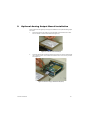
Chapter 9 Optional Analog Output Board Installation ....................................................................... 141
Chapter 10 Complete Menu Structures ............................................................................................... 145
Supervisor and User Menus .......................................................................................... 145
Service Menu ................................................................................................................. 146
Chapter 11 Technical Illustrations ....................................................................................................... 147
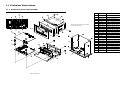
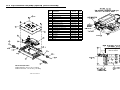
Enclosure parts and assembly ....................................................................................... 147
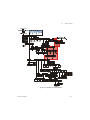
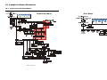
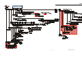
System block diagram .................................................................................................... 148
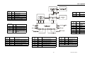
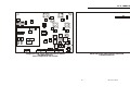
1080 PC Boards ............................................................................................................. 149
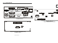
1080 PC Boards (cont.) ................................................................................................. 150
Trips interface unit (TIU3) (optional) parts & assembly .................................................. 151
Analog Output Card ....................................................................................................... 152
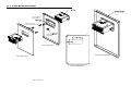
Panel Mount Illustrations ................................................................................................ 153
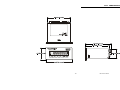
1080 Dimensional Drawings .......................................................................................... 154
4
1080 Service Manual
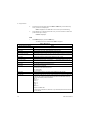
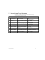
Manual revision history
Current
Issue
Date Created
Details of Changes
AA
January 2010
New manual
AB
January 2011
Added two pages in chapter 11. PC board illustrations.
AC
February 2011
Correction to step 3 and note in section 2.1, moved label on page 149.
AD
February 2011
Removed erroneous paragraph in section 4.1 about RS485 jumper
1080 Service Manual
5
6
1080 Service Manual
1.1
1
General information and warnings
1.1
About this manual
About this manual
This manual is divided into chapters by the chapter number and the large text at the top
of a page. Subsections are labeled as shown by the 1 and 1.1 headings shown above.
The names of the chapter and the next subsection level appear at the top of alternating
pages of the manual to remind you of where you are in the manual. The manual name
and page numbers appear at the bottom of the pages.
1.1.1 Text conventions
Key names are shown in bold and reflect the case of the key being described. If a key
has dual functions, the function is shown first followed by the key name in parentheses
and in bold, such as in these examples: F1, SELECT, PRINT, etc.
Displayed messages appear in bold italic type and reflect the case of the displayed
message.
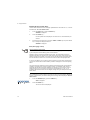
1.1.2 Special messages
Examples of special messages you will see in this manual are defined below. The
signal words have specific meanings to alert you to additional information or the relative
level of hazard.
WARNING!
This is a Warning symbol.
Warnings mean that failure to follow specific practices and procedures may
have major consequences such as injury or death.
CAUTION!
This is a Caution symbol.
Cautions give information about procedures that, if not observed, could result
in damage to equipment or corruption to and loss of data.
NOTE: This is a Note symbol. Notes give additional and important information, hints
and tips that help you to use your product.
1080 Service Manual
7
1 General information and warnings
1.2
Installation
NO USER SERVICEABLE PARTS. REFER TO QUALIFIED SERVICE
PERSONNEL FOR SERVICE.
1.2.1 Safe handling of equipment with batteries
CAUTION: Danger of explosion if battery is incorrectly replaced. Replace only
with the same or equivalent type recommended by the manufacturer. Dispose
of used batteries according to the manufacturer’s instructions.
ATTENTION: Il y a danger d'explosion s'il y a remplacement incorrect de la
batterie, remplacer uniquement avec une batterie du même type ou d'un type
équivalent recommandé par le constructeur. Mettre au rebut les batteries
usagées conformément aux instructions du fabricant.
1.2.2 Wet conditions
Under wet conditions, the plug must be connected to the final branch circuit via an
appropriate socket / receptacle designed for washdown use.
Installations within the USA should use a cover that meets NEMA 3R specifications
as required by the National Electrical Code under section 410-57. This allows the unit
to be plugged in with a rain tight cover fitted over the plug.
Installations within Europe must use a socket which provides a minimum of IP56
protection to the plug / cable assembly. Care must be taken to make sure that the
degree of protection provided by the socket is suitable for the environment.
1.3
Routine maintenance
IMPORTANT: This equipment must be routinely checked for proper operation
and calibration.
Application and usage will determine the frequency of calibration required for
safe operation.
Always turn off the machine and isolate from the power supply before starting any
routine maintenance to avoid the possibility of electric shock.
8
1080 Service Manual
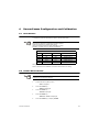
1.4
1.4
Cleaning the machine
Cleaning the machine
Table 1.1 Cleaning DOs and DON’Ts
DO
DO NOT
Wipe down the outside of standard products Attempt to clean the inside of the machine
with a clean cloth, moistened with water and Use harsh abrasives, solvents, scouring cleaners or
a small amount of mild detergent
alkaline cleaning solutions
Spray the cloth when using a proprietary
cleaning fluid
1.5
Spray any liquid directly on to the display windows
Training
Do not attempt to operate or complete any procedure on a machine unless you have
received the appropriate training or read the instruction books.
To avoid the risk of RSI (Repetitive Strain Injury), place the machine on a surface which
is ergonomically satisfactory to the user. Take frequent breaks during prolonged usage.
1.6
Sharp objects
Do not use sharp objects such as screwdrivers or long fingernails to operate the keys.
1.7
FCC and EMC declarations of compliance
United States
This equipment has been tested and found to comply with the limits for a Class A digital device, pursuant to Part 15 of the FCC Rules.
These limits are designed to provide reasonable protection against harmful interference when the equipment is operated in a
commercial environment. This equipment generates, uses, and can radiate radio frequency energy and, if not installed and used in
accordance with the instruction manual, may cause harmful interference to radio communications. Operation of this equipment in a
residential area is likely to cause harmful interference in which case the user will be required to correct the interference at his own
expense.
Canada
This digital apparatus does not exceed the Class A limits for radio noise emissions from digital apparatus set out in the Radio
Interference Regulations of the Canadian Department of Communications.
Le présent appareil numérique n’émet pas de bruits radioélectriques dépassant les limites applicables aux appareils numériques de
la Classe A prescrites dans le Règlement sur le brouillage radioélectrique edicté par le ministère des Communications du Canada.
European Countries
WARNING: This is a Class A product. In a domestic environment, this product may cause radio interference in which the user may be
required to take adequate measures.
1080 Service Manual
9
1 General information and warnings
1.8
10
Declaration of Conformity
1080 Service Manual
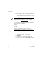
2
Introduction
This manual covers the information you need to setup, configure and service your 1080
indicator.
2.1
Unpacking and Setup
Unpack your indicator and check for any shipping damage. If shipping damage is
found, save all packing materials and contact the shipping company immediately.
1.
Use the included material and i nstall the indicator into an IP54 enclosure.
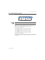
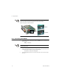
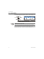
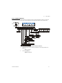
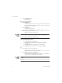
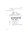
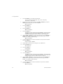
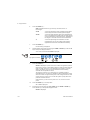
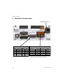
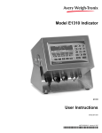
2.
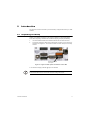
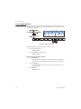
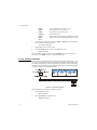
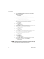
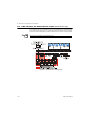
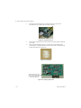
Connect all necessary cables to the appropriate connector on the back of the
indicator. See Figure 2.2. The function of each connector and pinout is clearly
marked.
Analog Output card
is an option
Figure 2.1 Figure 2.2 Rear panel connections on the 1080
3. Connect DC voltage (9-36 VDC @ 5A) to the indicator.
IMPORTANT: See the System Block Diagram or Main Board Assembly pages in the
technical illustrations at the back of this manual for wiring instructions.
1080 Service Manual
11
2 Introduction
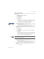
2.2
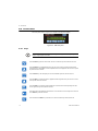
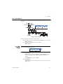
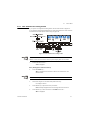
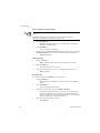
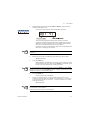
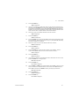
Front Panel
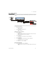
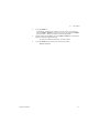
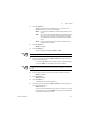
The front panel, shown in Figure 2.2, consists of the keys and display.
Figure 2.2 1080 front panel
2.2.1 Keys
Never press a key with anything but your finger. Damage to the overlay may result if
sharp or rough objects are used.
Press the TARE key to perform a tare function. Also acts as a left arrow key when in the menu structure.
Press the SELECT key to toggle between Gross, Net, Tare, Count, Gross Accumulator, Net Accumulator,
Transaction Counter, Piece Weight, and Peak. Dependent on the current application. Also acts as an up arrow
key when in the menu structure.
Press the ZERO key to zero the display. Also acts as an ESCAPE key when in the menu structure.
Press the PRINT key to send information to a peripheral device through the Comm port. Also acts as a down
arrow key when in the menu structure.
Press the UNITS key to scroll through the available units of measure while in normal operating mode. Also
acts as a right arrow key when in the menu structure.
Press the F1 key to select application specific choices. Press and hold to access the outputs menu. Also acts
as an ENTER key in the menu structure.
Press and release the ON/OFF key to turn the unit on. Press and hold the key until the unit turns off.
12
1080 Service Manual
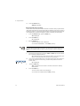
2.3
2.3
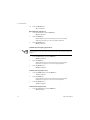
Numeric Entry Procedure
Numeric Entry Procedure
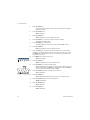
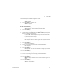
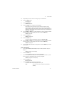
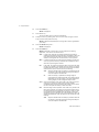
Some keys have alternate functions when you need to enter numbers. See Figure 2.
Figure 2.3 Alternate key functions
Press the ZERO key to terminate a value entry and leave the previous value, if any,
active
In screens where numeric entry is possible, choose the first digit using the UP or
DOWN keys. Use the LEFT and RIGHT keys to advance or backspace through the
entry. Press the F1 key to accept an entry. Below is an example:
Example: To enter the number 507Press the SELECT or PRINT key until 5 appears on the display.
Press the UNITS key once to move cursor one space to the right.
Press the SELECT or PRINT key until 0 appears on the display.
Press the UNITS key once to move cursor one space to the right.
Press the SELECT or PRINT key until 7 appears on the display.
Press the F1 key to enter the value.
You can move the entry function one digit to the left with a press of the TARE key. This
effectively deletes the current value in that position and allows you to enter a new value
in that position.
1080 Service Manual
13
2 Introduction
2.4
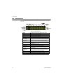
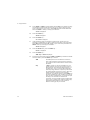
Annunciators
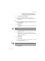
There are several annunciators around the edge of the display. Figure 2.4 explains
each one.
Figure 2.4 Annunciators.
14
Motion
Lights during scale motion. Goes out when scale is stable
Gross
Lights when gross weight is displayed
Net
Lights when net weight is displayed
Tare
Lights when tare weight is displayed
Print
Lights when print format sent through serial port
OP 1 (under)
Lights when output one is activated or for Under condition during
checkweighing
OP 2 (accept)
Lights when output two is activated or for Accept condition
during checkweighing
OP 3 (over)
Lights when output three is activated for Over condition during
checkweighing
PT
Lights when preset tare is active
Custom Unit
Lights when a custom unit of measure is active
Accumulator, Count
Lights when an accumulation occurs and while in the count and
peak applications
Network &
SensorComm
Status
This is configurable to light to show status of the Network 1,
Network 2 or SensorComm. See the note following this table.
LB
Lights when pounds is the active unit of measure
Center of Zero
Lights when weight on the scale is within the zero range
KG
Lights when kilograms is the active unit of measure
1080 Service Manual
2.5
Error Messages
Far Right LED color
(Chosen as SCOM or Network in configuration. Can’t be both.) SCOM:
Red – a cell has been ghosted. Check the ghost log.
Green – a sensorcomm error has occurred. Check the error log.
Off – Scale is functioning normally.
Network 1 or 2:
Red – A network error has occurred. Check the network settings on the indicator and
PLC, and reboot the indicator.
Green – The network connection has been established.
Amber – The network is ready for a connection, but no connection has been
established
2.5
Error Messages
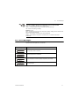
The following are displayed messages you may see if problems occur or if invalid
operations are attempted with your indicator:
Display
Description
Overrange weight. Scale is overloaded.
Underrange weight. Scale is underloaded.
The unit cannot perform a function. Displayed only while key is held down.
Displayed while a key is pressed when attempting to modify a sealed selection
without edit privileges.
1080 Service Manual
15
2 Introduction
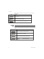
When you are in the Linearity menu item in the Service menu, you may see the
following errors:.
Display
Description
Out of ascending order.
Entered value is less than 1% of scale capacity.
Entered value causes resolution of greater than 100,000 divisions.
Linear points must be done in order from lightest weight to heaviest.
When you are in the Span menu item in the Service menu, you may see the following
errors:
Display
Description
Entered value is greater than the configured scale capacity.
Entered value is less than 1% of scale capacity.
Entered value causes resolution of greater than 100,000 divisions.
No ADC counts OR
in Overload OR
in Underload
16
All these relate to mV/V input
1080 Service Manual
3
Using the Menus
3.1
Available Menus
There are several menus you use to setup or service the 1080. You access the menus
through the front panel. Each menu is briefly described here. For in depth information
about a menu, go to that menu's section in this manual.
3.1.1 User menu (password is 111)
The first menu covered in this manual is the User menu. This menu allows the user to:
l
l
l
l
l
view software part numbers and revision level
view mV/V output of the scale
test the display and buttons
test the serial ports
audit the number of configurations and calibrations performed on the
indicator
For complete information, see User Menu on page 19.
3.1.2 Service menu (password is 0801)
The second menu covered is the Service menu. (See the note below about unsealing
the indicator.) In it you can:
l
l
l
l
l
l
l
calibrate the scale system
configure the metrological functions of the indicator
enable or disable available applications
configure serial ports
test the display and buttons, test the serial ports, test the inputs and outputs
audit the number of configurations and calibrations performed on the
indicator
configure inputs and outputs and options
For complete information, see Service Menu on page 22.
3.1.3 Supervisor menu (password is 1793)
The third menu is the Supervisor menu. This section lets you:
l
l
l
l
l
set time and date
clear and/or print data gathered by each application
choose special modes of operation for applications:
m configure a recipe, set sample mode, set over/under values, etc.
test the display and buttons, test the serial ports, test the inputs and outputs,
analog output, pulse counter input and networks
audit the number of configurations and calibrations performed on the
indicator
For complete information, see Supervisor Menu on page 102.
1080 Service Manual
17
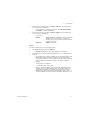
3 Using the Menus
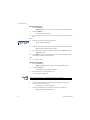
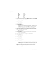
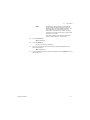
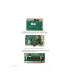
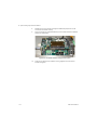
The indicator must be unsealed to change anything in the Service menu. To access
the menu a jumper must be placed over the pins of P2, shown below. Remove the
screws on the sides and top of the indicator to access the PC boards.
Remove the jumper to seal the indicator.
Sealed
Unsealed
3.2
Accessing the Menus
1.
Access the menus by pressing and holding the ZERO key for 3-5 seconds. See
the note below.
PASS_ is displayed.
You must begin to scroll in the password within 10 seconds or the display returns to
normal operation mode.
2.
Scroll in the password of the menu you want to enter by using the steps shown
in Numeric Entry Procedure on page 13 and press F1.
The first item in that menu is displayed.
3.
18
Use the navigation keys shown in the box near each menu to move through
the menu.
1080 Service Manual
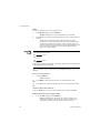
3.3
3.3
User Menu
User Menu
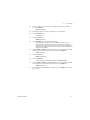
The User menu lets you test various functions of the indicator. The User menu is shown
in Figure 3.1.
Figure 3.1 User menu
Following are specific instructions for the User menu.
1.
Access the User menu by pressing and holding the ZERO key for 3-5 seconds.
PASS_ is displayed.
2.
Key in the User menu password (111) and press F1.
tESt is displayed.
Choose the first digit using the UP or DOWN keys. Use the LEFT and RIGHT keys to
advance or backspace through the entry.
3.
Press the PRINT key.
About is displayed. Press the PRINT key then the UNITS key to view
the part number and revision level for the software found in your
indicator.
Press SELECT key to return to About.
4.
Press the UNITS key…
AdC is displayed. This is the calibrated mV/V output of the connected
analog scale.
1080 Service Manual
19
3 Using the Menus
5.
Press the PRINT key…
The mV/V value is displayed. This value should increase as weight is
applied to the scale
6.
Press the SELECT key…
AdC is displayed.
7.
Press the UNITS key…
diSP is displayed. This is the display test item.
8.
Press the PRINT key to perform a dynamic test of the display…
All parts of the display flash.
9.
Press the ZERO key to stop the test…
The display flashes a couple more times and then diSP is shown.
10.
Press the UNITS key…
button is displayed. This is the button test item.
11.
Press the PRINT key to perform a button test. Each key you press will be
reflected on the display screen to confirm the button is functioning correctly.
The ZERO key is excluded from this test. It is used to stop the testing and
return to the menu item
12.
Press ZERO key to stop the button test.
button is displayed.
13.
Press the UNITS key…
SEriAL is displayed. This is the serial test item.
14.
Press the PRINT key to access the serial test.
Port1 is displayed. If you jumper the transmit and receive lines on the
serial port and press the PRINT key, the display should show PASS. If
there is a problem the display will show FAIL.
15.
Press the SELECT key after checking the port function…
Port1 is displayed.
16.
Press the UNITS key…
Port2 is displayed. Repeat the test from step 14 to check the port.
17.
Press the SELECT key twice to exit the serial test.
SEriAL is displayed.
18.
Press the SELECT key…
tESt is displayed.
19.
Press the UNITS key…
Audit is displayed.
20
1080 Service Manual
3.3
20.
User Menu
Press the PRINT key…
CFG is displayed. This stands for the configuration audit counter.
Calibration and configuration counters cannot be reset.
21.
Press the PRINT key to see the number of times the configuration has been
altered on this indicator.
22.
Press the SELECT key…
CFG is displayed.
23.
Press the UNITS key…
CAL is displayed. This stands for the calibration audit counter.
24.
Press the PRINT key…
The number of times the indicator has been calibrated is displayed.
25.
Press the ZERO key twice…
26.
The display returns to normal operation mode.
This completes the User menu.
1080 Service Manual
21
3 Using the Menus
3.4
Service Menu
The first level of the Service menu is shown in Figure 3.2. Under these items you can
do most of the configuration and calibration procedures to ready the indicator for use.
Figure 3.2 Service menu top level flowchart
Password for the Service menu is 0801.
While in a menu, the annunciators at the top of the display flash as a reminder.
Since the complete Service menu is quite large, it has been broken up into its individual
submenus. Each submenu is illustrated on the following pages with specific
instructions for that submenu. A full menu can be seen in Service Menu on page 146.
22
1080 Service Manual
3.4
Service Menu
3.4.1 CAL Submenu for Analog Scales
If your system is configured for analog scales, use the menu shown in Figure 3.3.
If your system is configured for SensorComm, follow the instructions in CAL submenu
for SensorComm scales (North America only) on page 128.
Figure 3.3 CAL submenu for analog scales
Password for the Service menu is 0801.
While in a menu, the annunciators at the top of the display flash as a reminder.
1.
Access the Service menu…
CAL is displayed.
Zero (Setting Zero Reference Point)
2.
Press the PRINT key…
ZEro is displayed. Use this item to set the zero reference for the
indicator/scale.
Press the ZERO key to abort calibration.
3.
Remove all weight from the scale and press the F1 key…
Live weight is shown.
4.
Press the F1 key to perform the zero procedure…
buSY is briefly displayed then the live weight which should be 0.
5.
Press the F1 key to save and return to the ZERO menu item…
ZEro is displayed.
1080 Service Manual
23
3 Using the Menus
SPAN (Setting Span)
1.
Press the UNITS key…
SPAn is displayed. Use this item to set the span for the indicator/scale.
2.
Press the PRINT key…
Current capacity is displayed.
3a.
Scroll in a new span weight value using the numeric entry procedure and press
F1
OR
3b.
Press F1 to accept current span weight value…
The live weight is displayed.
4.
Place the correct span weight on the scale and press F1 when weight is stable.
buSY is briefly displayed then the weight.
5.
Press the F1 key to accept the calibration and return to the SPAn menu item…
SPAn is displayed.
6a.
Press ZERO to exit to normal weighing mode (You will be prompted to save
the changes. Press F1 to save changes)
OR
6b.
Go to step 1 below.
LINEAR (Linearization)
1.
Press the UNITS key…
LinEAr is displayed. Use this item to set extra calibration points.
2.
Press the PRINT key…
2 is displayed. This represents cal point 2.
3.
Press the F1 key to set this calibration point…
A numeric value is displayed.
Linear points must be done in order from lightest weight to heaviest.
4.
Scroll in a weight value for this calibration point using the numeric entry
procedure and press the F1 key.
Live weight on the scale is displayed.
5.
Place the test weight for this calibration on the scale and press F1.
Busy is briefly displayed and then 2.
24
1080 Service Manual
3.4
6.
Service Menu
Press the UNITS key to move to the next calibration point…
3 is displayed.
7.
Repeat steps 3 through 6 for cal point 3 and 4.
When you are done, 4 will be displayed.
8a.
Press the SELECT key to return to the LinEAr menu item.
OR
8b.
Press the ZERO key to return to normal operating mode. You will be prompted
to save the changes. Press F1 to save them or the ZERO key to abort the save
process and return to normal operating mode without saving calibration.
INPUT (Input Calibration)
Use this item to hand enter zero and span calibration factors. This is useful if one
indicator fails and is replaced with another but no test weights are available.
Linearization factors cannot be entered.
To use this item you must have recorded the calibration factors from your previously
installed 1080 indicator.
Calibration factors can be viewed under CAL>INPUT or you can print them out using
the CAL>PRINT menu item.
1.
With LinEAr displayed, press the UNITS key…
InPut is displayed.
2.
Press the PRINT key…
ZEro is displayed.
3.
Press the PRINT key…
A numeric value is displayed.
4.
Scroll in the zero factor from your previous indicator using the numeric entry
procedure and press the F1 key.
buSY is briefly displayed, then ZEro.
5.
Press the UNITS key…
SPAn is displayed.
6.
Press the PRINT key…
A numeric value is displayed.
7.
Scroll in the span factor from your previous indicator using the numeric entry
procedure and press the F1 key…
A span weight is displayed.
8.
Accept the span weight by pressing the F1 key or key in a new span weight
and press the F1 key to accept it…
buSY is briefly displayed, then SPAn.
1080 Service Manual
25
3 Using the Menus
9.
Press the SELECT key to return to the InPut menu item.
DISP (Live Weight Display)
1.
With InPut displayed, press the UNITS key…
diSP is displayed. Use this item to view the live weight on the scale
without exiting the Service menu.
2.
Press the PRINT key…
The live weight is displayed.
3.
Press the SELECT key…
diSP. is displayed.
OR
3a.
Press the SELECT key to move to the top of the Service menu…
CAL is displayed.
PRINT (Print a Calibration Report)
1.
With CAL displayed, press the UNITS key…
Print is displayed. This item lets you print a calibration report. The
information printed can be very useful in case of service issues later.
2.
Press the PRINT key…
Port 1 is displayed. The other choice is Port 2. This allows you to
choose a port through which the calibration report is printed.
3.
Toggle between the choices using the TARE or UNITS key and press F1 when
your choice is displayed…
The report is printed and the display returns to Print.
4.
Press the ZERO key to return to normal operation mode.
SAvE is displayed.
5.
Press the F1 key to save changes or press the ZERO key to exit the menu
without saving.
This completes the CAL section of the Service menu for analog scales. If you have a
SensorComm system, see the chapter SensorComm Configuration and Calibration on
page 126 for calibration and configuration information.
The next Service menu item, SCALE, is covered in SCALE Submenu on page 27.
26
1080 Service Manual
3.4
Service Menu
3.4.2 SCALE Submenu
Use this section of the Service menu for scale configuration. Figure 3.4 shows this
menu item. Follow the directions and explanations below to set up these items.
Figure 3.4 Scale submenu flowchart
1.
Access the Service menu using the procedures in Accessing the Menus on
page 18…
CAL is displayed.
2.
Press the UNITS key…
SCALE is displayed.
1080 Service Manual
27
3 Using the Menus
Source (Analog or SensorComm)
Calibration instructions for Analog scales are in CAL Submenu for Analog Scales on
page 23.
Calibration instructions for SensorComm scales are in CAL submenu for
SensorComm scales (North America only) on page 128.
3.
Press the PRINT key…
SourCE is displayed. Use this item to choose between an analog or
SensorComm based system.
4.
Press the PRINT key…
The current setting is displayed.
5.
Toggle between the AnALoG and S-Com (North America only) choices using
the TARE or UNITS key. When your choice is displayed press the F1 key…
SourCE is displayed.
CAP. (Capacity)
1.
Press the UNITS key…
CAP. is displayed. Use this item to set the capacity for the scale.
2.
Press the PRINT key…
The current capacity value is shown.
3.
Press F1 to accept this value or key in a new capacity and press F1…
CAP. is displayed.
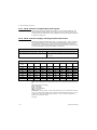
DIV. (Division)
This item and the next one, DP.POS., set the division size.
1.
Press the UNITS key…
div. is displayed. This stands for the division value of your displayed
weight.
2.
Press the PRINT key…
The current division value is shown.
3.
Scroll through the choices by using the TARE or UNITS key.
Pick from the following values; 1, 2, 5, 10, 20, 50, 100, 200 and 500
All of these capacities function in conjunction with the decimal place
position. For example, if you choose a division value of 5 and a decimal
position of 12345.6, your division size will be .5.
4.
When your choice is displayed, press F1.
div. is displayed.
28
1080 Service Manual
3.4
Service Menu
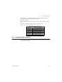
DP.POS. (Decimal point position)
Use this item to set the decimal point position in the displayed weight.
1.
Press the UNITS key…
dP.PoS. is displayed. This stands for decimal point position.
2.
Press the PRINT key…
The current decimal point position is shown. Choices available are;
123456, 12345.6, 1234.56, 123.456, 12.3456 and 1.23456.
3.
Scroll through the choices by using the TARE or UNITS key. When your
choice is displayed, press F1.
dP.PoS. is displayed.
UNITS (Unit of measure)
You can have up to three units of measure active. They are lbs, kgs, or a custom unit
of measure.
Follow these steps:
1.
Press the UNITS key…
UnitS is displayed.
2.
Press the PRINT key…
Lb is displayed.
3.
Turn each unit of measure on or oFF by scrolling to the unit by using the TARE
or UNITS key and pressing the PRINT key…
The current state of the unit is displayed.
4.
For lbs and kgs, toggle between on or oFF by using the TARE or UNITS key.
Press F1 when your choice is displayed…
Display returns to Lb or 1000 G.
1080 Service Manual
29
3 Using the Menus
4a.
If you choose to activate the custom unit of measure you will be prompted for
a multiplier which defines the custom unit in relation to the calibration unit of
measure and a string entry for a unit label. See the note below. Key the
multiplier in and press F1 to enter the value.
String entry screen is displayed. Edit the string (up to seven characters
long) to create a name for the custom unit of measure. For directions on
string editing, see the section Extra Info: Print Format Editing on page
47. String editing is covered in that section.
If your new custom unit is larger than one CAL UNIT, then you key in how many CAL
UNITS make up 1 new custom unit. For example 1 TON = 2000 pounds so with
pounds selected as our CAL UNIT we would key in 2000 for the multiplier.
If your new custom unit is smaller than one CAL UNIT, then you divide one cal unit by
the number of custom units it takes to make up a single CAL UNIT. Multipliers are
limited to a total of seven digits by the display.
Example #1:
16 ounces = 1 pound.
Do the math: (one cal unit / number of custom units = the multiplier)
1/16=0.0625
So with pounds selected as our CAL UNIT we would key in 0.0625 for the multiplier.
Example #2: 1000 Grams = 1 KG.
Do the math: (one cal unit / number of custom units = the multiplier)
1/1000=0.001
So with KG selected as our CAL UNIT we would key in 0.001 for the multiplier.
5.
Press F1 key to accept the string values …
CUSt. is displayed.
6.
Press the UNITS key…
C-Unit is displayed. This stands for calibration unit. Use this item to set
the calibration unit of measure; lbs or kgs (1000 G).
7.
Press the PRINT key…
Current calibration unit is displayed. Choices are lb or 1000G.
8.
Toggle between the choices by using the TARE or UNITS key and press the
F1 key to accept the choice…
C-Unit is displayed.
9.
Press the SELECT key…
UnitS is displayed.
30
1080 Service Manual
3.4
Service Menu
STABLE (Stability window)
Use this item to define the stability window in terms of ±X divisions for a period of time,
in seconds, you set.
1.
From the UnitS display, press the UNITS key…
StAbLE is displayed.
2.
Press the PRINT key…
div. is displayed.
3.
Press the PRINT key…
The current division size is displayed. If a weight changes less than this
number of divisions in the time period you select in the next steps, the
motion light turns off and the weight is considered stable.
You choices are 0.25, 0.5, 1, 3 and CUST. (custom).
4.
Scroll through the choices by using the TARE or UNITS key and press the F1
key to accept the displayed choice…
div. is displayed for any choice other than CUST. If you pick CUST. go to
step 5. If you picked any other division size, go to step 6.
5.
If you pick a custom window size you are shown the current value. Scroll in a
custom size using the numeric entry procedure and press F1 to save the
custom value…
div. is displayed.
6.
Press the UNITS key…
SEC. is displayed. Use this item to set the time window for stability
determination.
7.
Press the PRINT key…
The current time window size is displayed. If a weight changes less than
this number of divisions, set above, in the time period you select, the
motion light turns off and the weight is considered stable.
You choices are 1-10 seconds and CUST. (custom)
If CUSTOM is selected, only fractional time between 0-10 seconds can be entered.
Example: 1.5 seconds, 2.25 seconds, etc.
8.
Scroll through the choices by using the TARE or UNITS key and press the F1
key to accept the displayed choice…
SEC. is displayed for any choice other than CUST. If you pick CUST. go
to step 9. If you picked any other division size, got to step 10.
9.
If you pick a custom time you are shown the current value. Scroll in a custom
time using the numeric entry procedure and press F1 to save the custom
value…
SEC. is displayed.
1080 Service Manual
31
3 Using the Menus
10.
Press the SELECT key…
StAbLE is displayed.
AZT (Automatic Zero Tracking)
Use this item to set the division size and seconds. The division size you pick defines a
range above and below zero. When scale weight is inside this range for the number of
seconds you picked, ½ of the weight will be zeroed. The indicator will repeat removing
½ the weight every X seconds. X being the number of seconds you have picked.
1.
From the StAbLE display, press the UNITS key…
AZt is displayed.
2.
Press the PRINT key…
div. is displayed.
3.
Press the PRINT key…
The current division size is displayed.
You choices are 0.25, 0.5, 1, 3 and CUST. (custom)
For the purpose of explaining all items in the menus, these instructions show an
orderly accessing of each part of the menu. You do not have to access an item in this
way. Use the navigation buttons to skip around to the item you want to change or
view.
4.
Scroll through the choices by using the TARE or UNITS key and press the F1
key to accept the displayed choice…
div. is displayed for any choice other than CUST. If you pick CUST. go to
step 4a. If you picked any other division size, got to step 5.
4a.
If you pick a custom window size you are shown the current value. Scroll in a
custom size using the numeric entry procedure and press F1 to save the
custom value…
div. is displayed.
5.
.Press the UNITS key…
SEC. is displayed. Use this item to set the time window for stability
determination.
6.
Press the PRINT key…
The current time window size is displayed.
You choices are 1-10 seconds and CUST. (custom)
32
1080 Service Manual
3.4
7.
Service Menu
Scroll through the choices by using the TARE or UNITS key and press the F1
key to accept the displayed choice…
SEC. is displayed for any choice other than CUST. If you pick CUST. go
to step 7a. If you picked any other division size, got to step 8.
If CUSTOM is selected, only fractional time between 0-10 seconds can be entered.
Example: 1.5 seconds, 2.25 seconds, etc.
7a.
If you pick a custom time you are shown the current value. Scroll in a custom
time using the numeric entry procedure and press F1 to save the custom
value…
SEC. is displayed.
8.
Press the SELECT key…
AZt is displayed.
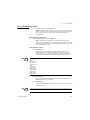
TARE (Tare parameters)
Use this item to set the tare function parameters;
1080 Service Manual
Clear tare
If you enable this item (on), the tare will be automatically cleared
when the weight falls below the value set under the G-Band menu
item.
Pushbutton tare
If you enable this item (on), you can use the TARE key to tare a
weight from the scale. If you disable (oFF) this item, you cannot
tare using the TARE key.
A-Tare
If you enable this item (on), the indicator will automatically tare off
any weight on the scale when the weight is both above a
configurable threshold and stable. Under this item set the
following:
Enable
Enable (on) or disable (oFF) the Auto-tare feature.
Lo
Set the lower threshold (Lo) in % of scale capacity.
When the weight on the scale is above the lower
threshold and below the upper threshold and the
delay has expired and the weight is stable, an autotare is triggered.
Hi
Set the upper (Hi) threshold in % of scale capacity.
When the weight on the scale is above the lower
threshold and below the upper threshold and the
delay has expired and the weight is stable, an autotare is triggered.
A-Print
Enable (on) or disable (oFF) the Auto-print feature. If
on, a print will occur whenever an automatic tare is
done.
Delay
This defines the amount of time (in seconds), after the
weight falls into the auto-tare window, until an autotare is done.
33
3 Using the Menus
Follow these steps to set the Tare item:
1.
From the AZt display, press the UNITS key…
tArE is displayed.
2.
Press the PRINT key…
CLEAr is displayed.
3.
Press the PRINT key…
on or oFF is displayed. Use this to enable or disable the Clear tare item.
4.
Toggle between the choices by using the TARE or UNITS key and press the
F1 key to accept the displayed choice…
CLEAr is displayed.
5.
Press the UNITS key…
P.b. is displayed.
6.
Press the PRINT key…
on or oFF is displayed. Use this to enable or disable the Pushbutton tare
item.
7.
Toggle between the choices by using the TARE or UNITS key and press the
F1 key to accept the displayed choice…
P.b. is displayed.
8.
Press the UNITS key…
A-tarE is displayed.
9.
Press the PRINT key…
EnAbLE is displayed. Use this to enable or disable the Pushbutton tare
item.
10.
Press the PRINT key…
on or oFF is displayed. Use this to enable or disable the Auto-tare item.
11.
Toggle between the choices by using the TARE or UNITS key and press the
F1 key to accept the displayed choice…
EnAbLE is displayed.
12.
Press the UNITS key…
Lo is displayed.
13.
Press the PRINT key…
A numeric entry screen appears.
14.
Use the numeric entry procedure to enter in a low threshold value and press
the F1 key to accept.
Lo is displayed.
15.
Press the UNITS key…
Hi is displayed.
34
1080 Service Manual
3.4
16.
Service Menu
Press the PRINT key…
A numeric entry screen appears.
17.
Use the numeric entry procedure to enter in a high threshold value and press
the F1 key to accept.
Hi is displayed.
18.
Press the UNITS key…
A-Prnt is displayed.
19.
Press the PRINT key…
on or oFF is displayed. Use this to enable or disable the Auto-tare print
function.
20.
Toggle between the choices by using the TARE or UNITS key and press the
F1 key to accept the displayed choice…
A-Prnt is displayed.
21.
Press the UNITS key…
Delay is displayed.
22.
Press the PRINT key…
A numeric entry screen appears.
23.
Use the numeric entry procedure to enter in a delay time, in seconds, and
press the F1 key to accept.
Delay is displayed.
24.
Press the SELECT key twice…
tArE is displayed. This completes the Tare item.
1080 Service Manual
35
3 Using the Menus
UPDATE (Display Update Rate)
Use this item to set the number of display updates/second. Choices are 1, 2, 5 and 10
times/second. 10 is the default value.
1.
From the tArE display, press the UNITS key…
UPdAtE is displayed.
2.
Press the PRINT key…
Current update rate is displayed. Choices are 1, 2, 5 and 10 times per
second.
3.
Scroll through the choices by using the TARE or UNITS key and press the F1
key to accept the displayed choice…
UPdAtE is displayed.
AVG (Averaging of A-D)
General Filtering Information
The AvG and FiLtEr menu items discussed on the following pages are best explained
by an example of how the filtering works in this indicator.
Filtering is used to counteract vibration of the scale. The A-D weight conversion
happens 100 times per second in the 1080. AVG is the number of conversions you
want to average. For example, if you pick 50, the unit will average the weight values
from the last 50 conversions or ½ second and uses that value for displayed data.
If you turn the filtering on you need to set the Constant. Typical values are between 110. Set the number low for small vibration problems and higher for more dampening
effect.
The purpose of the Threshold is so the indicator will respond quickly to large weight
changes. Threshold is the amount of weight change, in calibration units, beyond
which the filter will be temporarily disabled. For example, if you set this to 10 lbs, a
weight change over 10 pounds occurring during the sample time (½ sec. in our
example) will disable the filter until the weight change during the sample time drops
below 10 lbs.
The A-D weight conversion happens 100 times per second in this indicator. AvG is the
number of conversions you want to average for the weight that is displayed. 20 is the
default value.
1.
From the UPdAtE display, press the UNITS key…
AvG is displayed.
2.
Press the PRINT key…
The current value is displayed.
36
1080 Service Manual
3.4
3a.
Service Menu
Press F1 to accept the current value
OR
3b.
Scroll in a new value, between 0 and 512, using the numeric entry procedure
and press F1 to accept it…
buSY is briefly displayed, then AvG.
FILTER (Noise filtering)
Use this item to set the noise filtering parameters.
1.
From the AvG display, press the UNITS key…
FiLtEr is displayed.
2.
Press the PRINT key…
Current setting is displayed. Choices are oFF, FLtr 1 and FLtr 2.
Off means no filtering. FLTR 1 filtering is slower response to weight in a
longer time period with improved accuracy. FLTR 2 filtering is faster
response to weight in a short time.
3.
Scroll through the choices by using the TARE or UNITS key and press the F1
key to accept the displayed choice…
If you choose oFF, display returns to FiLtEr. You can continue to the
next menu item, D.POINT (Decimal point) on page 38.
If you choose FLtr 1 or 2, continue to step 4.
4.
With FLtr 1 or FLtr 2 displayed, press the PRINT key…
ConSt is displayed. This stands for Constant and is one of two filtering
parameters you need to set.
5.
Press the PRINT key…
Current value is displayed. For the Constant value you can pick a value
between 1 and 10. Set the number low for small vibration problems and
use a higher setting for more dampening effect.
6.
Scroll through the choices by using the TARE or UNITS key and press the F1
key to accept the displayed choice…
ConSt is displayed.
1080 Service Manual
37
3 Using the Menus
7.
Press the UNITS key…
tHrESH is displayed. This stands for Threshold, the 2nd filtering
parameter.
Threshold causes the indicator to respond quickly to large weight
changes. Threshold is the amount of weight change, in calibration units,
beyond which the filtering will be temporarily disabled. For example, if
you set this to 10 lbs, a weight change over 10 pounds occurring during
the sample time will disable the filtering until the weight change during
the sample time drops below 10 lbs.
A threshold setting of 0 will turn filtering on all the time.
8.
Press the PRINT key…
Current value is displayed.
9.
Scroll in a value using the numeric entry procedure. Press the F1 key…
tHrESH is displayed.
10.
Press the SELECT key…
FLtr 1 or FLtr 2 is displayed.
11.
Press the SELECT key…
buSY is displayed briefly then FiLtEr. Whichever filter you set up
becomes the active filter for the indicator.
D.POINT (Decimal point)
Use this item to toggle between decimal point and a comma for the fraction delimiter
for the display. For example, if you pick DEC the display will show 10.5. If you pick
COMMA, the display will show 10,5.
1.
From the FiLtEr display, press the UNITS key…
d.Point is displayed.
2.
Press the PRINT key…
The current setting is displayed.
Example:
decimal = 000.00
comma = 000,00
3.
Toggle between the choices, dEc or coma, by using the TARE or UNITS key
and press the F1 key to accept the choice…
d.Point is displayed.
38
1080 Service Manual
3.4
Service Menu
0-RANGE (Zero range)
Use this item to key in a percentage of capacity, within which the ZERO key will zero
the scale.
1.
From the d.Point display, press the UNITS key…
0-rngE is displayed.
2.
Press the PRINT key…
The current setting is displayed. This is a percentage of capacity.
3a.
Scroll in a new value using the numeric entry procedure and press F1 to
accept the value
OR
3b.
Press the F1 key to accept the displayed choice…
0-rngE is displayed.
O-CAP. (Over capacity range)
Use this item to set the point at which over range (upper) dashes are displayed. You
can choose between 105% of capacity or Divisions (+9/-20 div.) over and under
capacity.
1.
From the 0-rngE display, press the UNITS key…
O-CAP. is displayed.
2.
Press the PRINT key…
The current setting is displayed.
3.
Toggle between the choices by using the TARE or UNITS key and press the
F1 key to accept the choice…
O-CAP. is displayed.
G-BAND (Gross zero band)
Use this item to set the gross zero band. This is a parameter used to trigger the tare
clear function covered previously in the Scale submenu. It also sets the Return to Zero
range for Autoprint, Accumulate, Checkweighing and Counting functions. You can
enter values between 0 and 100 divisions.
1.
From the O-CAP. display, press the UNITS key…
G-bAnd is displayed.
2.
Press the PRINT key…
The current setting is displayed.
3a.
Scroll in a new value using the numeric entry procedure and press F1 to
accept the value
OR
3b.
Press the F1 key to accept the displayed choice…
G-bAnd is displayed.
1080 Service Manual
39
3 Using the Menus
C-ZERO (Center of zero window)
This item is to set the window size for the center-of-zero annunciator. You can choose
between ±¼ and ±½ division. When the weight falls within the window size, the centerof-zero annunciator lights.
1.
From the G-bAnd display, press the UNITS key…
C-ZEro is displayed.
2.
Press the PRINT key…
The current setting is displayed.
3.
Toggle between the choices by using the TARE or UNITS key and press the
F1 key to accept the choice…
C-ZEro is displayed.
SERIAL (Serial number entry)
Use this item to enter the serial number for your indicator. This value is used in some
serial outputs and reports for record keeping purposes.
1.
From the C-ZEro display, press the UNITS key…
SEriAL is displayed.
2.
Press the PRINT key…
The current setting is displayed.
The serial number of your indicator can be found on the affixed tag on the outside of
the indicator case.
3a.
Scroll in the serial number of your indicator using the numeric entry procedure
and press F1 to accept the value
OR
3b.
Press the F1 key to accept the displayed choice…
SEriAL is displayed.
4.
This completes the SCALE portion of the Service menu. You can exit to normal
weighing mode or continue on to the next menu item, APP. To exit, go to step
5. To continue, go to step 7.
5.
Press the ZERO key.
SAvE is displayed.
6a.
Press F1 to save the changes you’ve made
OR
6b.
Press ZERO to abort the changes…
Display returns to normal operation mode.
40
1080 Service Manual
3.4
7.
Service Menu
Press the SELECT key…
SCALE is displayed.
8.
Press the UNITS key…
APP is displayed.
3.4.3 APP (Applications) submenu
The next section of the Service menu is the APP (Applications) submenu. See Figure
3.5. This menu lets you choose the default parameters for your location and also lets
you enable or disable each application available in this indicator. Under each enabled
application you can edit the default print format (#0) and choose which formats (#0-10)
to print and through which port. You can configure the extra formats (#1-10) in the
SERIAL submenu item in the Service menu.
See the Communications section of the User Manual for print format information.
Figure 3.5 APP (applications) submenu
IMPORTANT: Only one application can be active or enabled at one time. If you
enable one, any other enabled application becomes automatically disabled.
Applications are enabled in the Service menu but you do each application’s setup in
the Supervisor menu.
Follow these steps to access each item in the APP menu and to understand what they
do and how to set them:
1.
Access the Service menu…
CAL is displayed.
1080 Service Manual
41
3 Using the Menus
2.
Press the UNITS key twice…
APP. is displayed.
SITE (Setting site defaults)
3.
Press the PRINT key…
SitE is displayed. Use this item to choose your instrument location; NA
(North America), EU (Europe). Choosing the correct one will set defaults
to your location’s requirements.
4.
Press the PRINT key…
Current setting is displayed.
5.
Toggle between the choices by using the TARE or UNITS key and press the
F1 key to accept the displayed choice…
SitE is displayed. See the note below.
Master Reset - If you change the site setting and save the change, then change it
back to the original site and save, the defaults will be reset to factory defaults.
This will not affect calibration, print formats or recipes.
ACC (Accumulator application)
1.
From the SitE display, press the UNITS key…
Acc. is displayed. This stands for the Accumulator application.
2.
Press the PRINT key…
on or oFF is displayed, depending on the current setting.
3a.
Press the SELECT key to back out of this item without enabling it
OR
3b.
Press the F1 key to enable this application…
StrinG is displayed. This is where you can choose a port to print through
and view and/or edit the default print format.
4.
With StrinG displayed, press the PRINT key…
The current port setting appears. Choices are Port 1, Port 2, TCPIP1,
TCPIP2, SMTP 1 or SMTP 2. See the note below.
If you choose TCPIP1 or SMTP1, Net 1 under OPTION>NETS must be set to E-net-1
or E-net-4.
If you choose TCPIP2 or SMTP2, Net 2 under OPTION>NETS must be set to E-net-1
or E-net-4.
42
1080 Service Manual
3.4
5.
Service Menu
Toggle between the choices with the TARE or UNITS key and press F1 to
accept the displayed choice…
A string of numbers appears. See example and note below.
These numbers represent the default print format in numbered
sequence of hexadecimal commands. Each hexadecimal command
represents one printing character or print command. These numbers
allow you to customize the print output of the indicator.
See Extra Info: Print Format Editing on page 47 for full explanation and
instruction on modifying a print format.
There are default print formats for each application. These are all given a format
number = 0.
6.
Modify the print format as needed and press the F1 key when finished…
StrinG is displayed.
7.
Press the UNITS key…
P-Ft is displayed. This stands for print format. You can send one or more
print formats through a port each time the PRINT key is pressed. This is
the item you use to define which formats get printed.
You can exit the Service menu at any time by pressing the ZERO key. When SAvE
appears on screen you can press ZERO to lose any changes or press F1 to save the
changes and return to normal operating mode.
8.
Press the PRINT key…
Numeric entry screen is displayed.
9.
Scroll in the format numbers you want printed using the numeric entry
procedure. See note below. For example, to print formats 0, 1, and 4, key in
014 and press the F1 key. To print the 0, 1, 3, and 10 formats, key in 01310
and press the F1 key…
P-Ft is displayed.
When you scroll in a 1 followed by a 0, the indicator is smart enough to know this is a
10 not separate 1 and 0 formats.
Always enter format numbers in ascending order.
1080 Service Manual
43
3 Using the Menus
10.
Press the SELECT key…
Acc. is displayed.
BATCH (Batch application)
1.
From the Acc. display, press the UNITS key…
bAtch is displayed.
2.
Press the PRINT key…
Repeat steps 2 through 9 from the section ACC (Accumulator
application) on page 42, to set up the Batch application.
3.
Press the SELECT key…
bAtch is displayed.
TARGET (Checkweighing application)
Outputs 1, 2 and 3 must be turned on for the checkweighing annunciators (Over,
Accept, Under) to work. This is done in the Service menu. See OUTPUT submenu on
page 72
1.
From the bAtch display, press the UNITS key…
tArGEt is displayed.
2.
Press the PRINT key…
Repeat steps 2 through 9 from the section ACC (Accumulator
application) on page 42, to set up the Target application.
3.
Press the SELECT key…
tArGEt is displayed.
COUNT (Counting application)
1.
From the tArGEt display, press the UNITS key…
Count is displayed.
2.
Press the PRINT key…
Repeat steps 2 through 9 from the section ACC (Accumulator
application) on page 42, to set up the Count application.
3.
Press the SELECT key…
Count is displayed.
TOP (Peak hold application)
1.
From the Count display, press the UNITS key…
tOP is displayed.
44
1080 Service Manual
3.4
2.
Service Menu
Press the PRINT key…
Repeat steps 2 through 9 from the section ACC (Accumulator
application) on page 42, to set up the Top application.
3.
Press the SELECT key…
tOP is displayed.
R-DISP (Remote Display)
1.
From the tOP display, press the UNITS key…
r-diSP is displayed.
2.
Press the PRINT key…
on or oFF is displayed, depending on the current setting.
3.
Press the PRINT key…
Port is displayed. Use this item to select which port the master indicator
will use to communicate with this remote display.
4.
Press the PRINT key…
The current port selection is displayed. Choices are Port 1, Port 2,
TCPIP 1 or TCPIP 2.
5.
Scroll through the choices by using the TARE or UNITS key. Press the F1 key
when your choice is displayed…
Port is displayed.
6.
Press the UNITS key…
ModE is displayed. Use this item to configure how the remote will
operate.
7.
Press the PRINT key…
Current mode value is displayed.
8.
MODE 1
Indicator displays gross annunciator, weight and
units annunciator. This is an emulation of the
RD4100 remote display.
MODE 2
Indicator does the same thing as Mode 1 plus
annunciators reflect the main display status.
MODE 3
Indicator acts as Mode 1 plus the following keys
work; TARE, SELECT, ZERO, PRINT and UNITS.
MODE 4
Indicator acts the same as in Mode 3 plus all the
annunciators reflect the main display status
Scroll through the choices using the TARE or UNITS key. When your choice is
displayed, press the F1 key…
ModE is displayed.
1080 Service Manual
45
3 Using the Menus
GENRAL (General weighing application)
1.
From the ModE display, press the UNITS key…
GEnrAL is displayed. This is the general weighing function. This is the
default application in a new indicator.
2.
Press the PRINT key…
Repeat steps 2 through 9 from the section ACC (Accumulator
application) on page 42, to set up the General application.
3.
Press the SELECT key…
GEnrAL is displayed.
SPLIT (Axle weighing application)
1.
From the GEnrAL display, press the UNITS key…
SPLIt is displayed. This is the axle weighing application.
2.
Press the PRINT key…
Repeat steps 2 through 9 from the section ACC (Accumulator
application) on page 42, to set up the Split application.
3.
Press the UNITS key…
dELAY is displayed. This is the maximum time, in seconds, the driver
has once the first axle leaves the scale to the next axle coming on the
scale.
4.
Press the PRINT key…
The numeric entry screen appears. Use the numeric entry procedure to
enter a delay time, in seconds.
5.
Press the F1 key to accept…
dELAY is displayed.
6.
Press the UNITS key…
div. is displayed. This is the minimum weight for an axle, in divisions.
The weight must go above this and become stable before the scale
captures the weight.
7.
Press the PRINT key…
The numeric entry screen appears. Use the numeric entry procedure to
enter the number of divisions.
8.
Press the F1 key to accept…
div. is displayed.
9.
Press the SELECT key twice…
APP. is displayed.
10.
Press the ZERO key to exit the Service menu…
SAvE is displayed.
46
1080 Service Manual
3.4
11.
Service Menu
Press F1 to save your changes or press ZERO to abort any changes made in
the Service menu…
buSY flashes until the indicator returns to normal operation mode.
This completes the APP menu.
3.4.4 Extra Info: Print Format Editing
The first three numbers are the sequence of the print commands. The last two
characters are the hexadecimal number for the print command.
Use the keys as described in Figure 3.6 to scroll through the sequence and change the
hex. character value.
Figure 3.6 Key legend for hex editing
1080 Service Manual
TARE
moves to the previous sequence number
SELECT
increments hex character up
ZERO
Toggles between first and second hex digit
PRINT
decrements hex character down
UNITS
moves right through the print string
F1
Accepts print string and exits edit mode
ON/OFF
A short key press inserts a new character in front of the displayed
character. Press and hold to delete the currently displayed hex
character.
47
3 Using the Menus
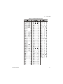
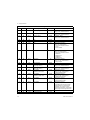
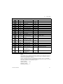
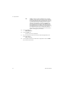
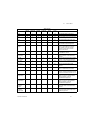
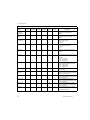
Hex values of 7F (127 decimal) and below are printable characters and can be seen in
Table 3.1. Hex values from 80 (128 decimal) to FF (255 decimal) is for print command
tokens and can be seen in Table 2: Printing Commands Chart on page 52. See note
below.
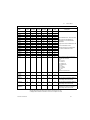
FF is the hex. value for End of String (EOS). When this value is entered in a print
format, any values beyond this in the sequence are ignored and the display will wrap
back to the 001 item.
You can overwrite the FF value and use up to the maximum string length if so desired.
In the 1080 the maximum sequence length is 256. However, the last character in the
print format must be FF. Be sure to add the FF character if it is removed.
The default print formats for each application are shown below.
Print Formats 1-8 are for the Zebra Thermal printer. See examples on the following
pages.
Print Formats 9 & 10
G
123456 lb
{ACT}{DSP}{UN}<CR><LF>{EOS}
Accumulator Print Format 11, Batching Print Format 12, and Checkweigher Print
Format 13, General Application Print Format 23 and Axle Weighing Application
Print Format 24 all use the following:
G
123456 lb
{ACT}{DSP}{UN}<CR><LF>{EOS}
Counting, Print Format 14
Count: 48
Count: {CNT}<CR><LF>{EOS}
Peak, Print Format 15
123456 lb
{PWT} {UN}<CR><LF>{EOS}
Remote Display, Print Format 16
G
123456 lb
{ACT} {DSP} {UN}<CR><LF>{EOS}
The following are the default print formats are for the corresponding “Mode” setting in
the serial port configuration menu.
48
1080 Service Manual
3.4
Service Menu
17 Port 1 Enquire (HEX05)
18 Port 1 Broadcast
19 Port 1 RD4100
20 Port 2 Enquire (HEX05)
21 Port 2 Broadcast
22 Port 2 Remote display
G
123456 lb
{ACT} {DSP} {UN}<CR><LF>{EOS}
1080 Service Manual
49
3 Using the Menus
3.4.5 Thermal Labels Print Formats
Print Formats 1, 2 & 3
Time
Date
G
Gross Weight
T
Tare Value
N
Net Weight
Format 1 label 1.25” Wide x 1.00” Long
Format 2 label 2.50” Wide x 4.00” Long
Format 3 label 4.00” Wide x 6.00” Long
Print Format 4, same as above with barcode.
Label Size:
2.50” Wide
4.00” Long
Print Formats 5, 6 & 7
Time
Date
PLU Totals Information
Gross Total Accumulator
Format 5 label 1.25” Wide x 1.00” Long
Format 6 label 2.50” Wide x 4.00” Long
Format 7 label 4.00” Wide x 6.00” Long
Print Format 8, same as above with barcode.
Label Size
2.50” Wide
4.00” Long
50
1080 Service Manual
3.4
Service Menu
Table 3.1 Printable Characters Chart
1080 Service Manual
51
3 Using the Menus
Table 2: Printing Commands Chart
Dec
HEX
Token
128
80
GWT(,n)
Gross Weight [1]
Weight
OPTIONAL, (ASCII)
Range: (‘2’-‘9’), Indicator Default: ‘6’
129
81
NWT(,n)
Net Weight [1]
Weight
OPTIONAL, (ASCII)
Range: (‘2’-‘9’), Indicator Default: ‘6’
131
83
SAT(,n)
Semi-Auto Tare [1]
Weight
OPTIONAL, (ASCII)
Range: (‘2’-‘9’), Indicator Default: ‘6’
132
84
UN
Units
Weight
135
87
ID
Scale Serial Number
Misc
136
88
TIM,x
Time
Time
MANDATORY (DECIMAL)
Range: (0-2), Editor Default:1
0= Format as set/active in indicator
1= hh:mm
2= hh:mm AM/PM
137
89
DAT,x
Date
Date
MANDATORY, (DECIMAL)
Range: (0-4), Editor Default:1
0= Format as set/active in indicator
1= MM/DD/YY
2= MM/DD/YYYY
3= DD/MM/YY
4= DD/MM/YYYY
138
8A
TTV,n
Target Value
Trip
MANDATORY, (HEX #s)
Range: (‘31’-‘33’), Editor Default: ‘1’
For target weights
140
8C
AXL
142
8E
CLA(,n)
Checkweigher
‘Low Accept’ value [1]
Checkweight
OPTIONAL, (ASCII)
Range: (‘2’-‘9’), Indicator Default: ‘6’
143
8F
CHA(,n)
Checkweigher
‘High Accept’ value [1]
Checkweight
OPTIONAL, (ASCII)
Range: (‘2’-‘9’), Indicator Default: ‘6’
144
90
RAV,n
Active Recipe
Ingredient x ‘Actual’ value
Recipe
MANDATORY, (HEX #s)
Range: (‘31’-‘38’), Editor Default: ‘1’
For target weights in recipe
145
91
RTV,n
Active Recipe
Ingredient x ‘Target’ value
Recipe
MANDATORY, (HEX #s)
Range: (‘31’-‘38’), Editor Default: ‘1’
For preact values in recipe
146
92
RPV,n
Active Recipe
Ingredient x ‘Preact’ value
Recipe
MANDATORY, (HEX #s)
Range: (‘31’-‘38’), Editor Default: ‘1’
For target weights in recipe
147
93
RIU,n
Active Recipe
Ingredient x units
Recipe
MANDATORY, (HEX #s)
Range: (‘31’-‘38’), Editor Default: ‘1’
For ingredient units (lb or kg for weight
based ingredients; sec for time based
ingredients; cnts or gallons for pulse
counter based ingredients). To be printed
after the target or actual ingredient value.
148
94
PCE
Piece Weight
Count
149
95
CNT
Current Count Value
Count
52
Application
Last axle weight
Group
Parameter
Vehicle
1080 Service Manual
3.4
Service Menu
Table 2: Printing Commands Chart
Dec
HEX
Token
Application
Group
151
97
GTO
Gross Accumulator
152
98
GTU
Clears G, T or N Accum in print
153
99
STO
Net Accumulator
Weight
155
9B
PLU
PLU NumberData
PLU
156
9C
DES
PLU ID
PLU
162
A2
DIS
Remote Display Status
Miscellaneous
170
AA
VER
Software Version Number
Miscellaneous
173
AD
WST
Weight Steady
178
B2
PUP
Tare associated with the PLU
PLU
184
B8
PUT
PLU Totals Information
PLU
188
BC
PCT
PLU Count Total
PLU
189
BD
LST
Net Accumulator
PLU
190
BE
LGT
Gross Accumulator
PLU
200
C8
DSP(,n)
215
D7
216
Parameter
Weight
Misc.
Weight
Print the displayed weight
Weight
NULL
Null Token
Strings
D8
ACT
Print the active value (‘G’ for
gross, ‘N’ for net, ‘T’ for tare)
Weight
230
E6
DRT
Remote display token-Axle
mode
Vehicle
231
E7
HST
Active Value-Axle mode
Vehicle
233
E9
AXT
Axle total
Vehicle
242
F2
PWT
Peak Hold Weight value
Weight
246
F6
MWR
Axle index
Vehicle
253
FD
HEX,xx
254
FE
TEX
Reserved for future use
as a ‘token extender’
255
FF
EOS
End of String
Following number will be
transmitted by value. Also,
use this selection to
transmit a NUL as well.
Hex-Codes
OPTIONAL, (ASCII)
Range: (‘2’-‘9’), Indicator Default: ‘6’
MANDATORY, (ASCII-HEX)
Range: (00 – FF), Editor Default: 00
----String
Notes:
These tokens can be optionally followed by an ASCII 2 to 9 to specify the number of
weight digits (including decimal point). If no specifier is given it defaults to 6 digits (+
decimal point) (equivalent to ASCII 6).
Further, parameter values may be ASCII digits (i.e. range ‘0’ thru ‘9’) or DECIMAL
values (i.e. range 0 thru 255). In all cases, parameters consume one byte. In the term/
token table parameters are indicated as follows:
Optional, (ASCII)
Optional, (Decimal)
Mandatory, (ASCII)
Mandatory, (Decimal)
1080 Service Manual
-
(,n)
(,x)
,n
,x
53
3 Using the Menus
3.4.6 SERIAL submenu
The next section of the Service menu is the SERIAL submenu. See Figure 3.7. This
menu lets you configure the serial ports and create custom print formats #1-10.
Figure 3.7 SERIAL (serial communication) submenu
The default serial port parameters are 9600 baud, 8 databits, no parity and 1 stop bit.
Stop bits for the serial communication are preset to 1 stop bit. This is not
configurable.
Follow these steps to access each item in the SERIAL menu and to understand what
they do and how to set them:
1.
Access the Service menu…
CAL is displayed.
2.
Press the UNITS key repeatedly until…
SEriAL is displayed.
3.
Press the PRINT key…
Port 1 is displayed.
54
1080 Service Manual
3.4
Service Menu
Port 1 or Port 2
4.
Scroll through the other choices, Port 2 and StrinG, by using the TARE or
UNITS key and press the F1 key to accept the displayed choice. If you choose
Port 1 or Port 2, continue with the rest of this step. If you choose StrinG, go to
STRING (Custom print formats) on page 63.
All the port configuration items are identical for Port 1 and Port 2 except
port 1 has two additional TYPE selections (RS-485 and 485HD). Use the
following steps to configure each port.
bAud is displayed. Use this item to set the baud rate.
BAUD (Baud rate)
1.
From the bAud display, press the PRINT key …
Current baud rate is displayed. Choices are from 300 to 115,200.
Default is 9600.
2.
Scroll the choices by using the TARE or UNITS key and press the F1 key to
accept the displayed choice…
bAud is displayed.
D-BITS (Data Bits)
3.
From the bAud display, press the UNITS key…
d-bitS is displayed. Use this item to set the data bits value.
4.
Press the PRINT key…
7 or 8 is displayed.
5.
Toggle between the choices by using the TARE or UNITS key and press the
F1 key to accept the displayed choice…
d-bitS is displayed.
PARITY (Parity setting)
1.
From the d-bitS display, press the UNITS key…
PAritY is displayed. Use this item to set parity.
2.
Press the PRINT key…
nonE, Odd or EvEn is displayed.
3.
Scroll through the choices by using the TARE or UNITS key and press the F1
key to accept the displayed choice…
PAritY is displayed.
1080 Service Manual
55
3 Using the Menus
C-TROL (Handshake control)
1.
From the PAritY display, press the UNITS key…
C-trol is displayed. Use this item to set the handshake control.
2.
Press the PRINT key…
nonE, rtS or SoFt (Xon/Xoff) is displayed. See note below.
rtS appears under Port 2 only, not under Port 1.
3.
Scroll through the choices by using the TARE or UNITS key and press the F1
key to accept the displayed choice…
C-trol is displayed.
TYPE (Serial port mode)
1.
From the C-trol display, press the UNITS key…
tYPE is displayed. Use this item to set the port mode.
2.
Press the PRINT key…
Current setting is displayed. These are the choices you scroll through in
step 3:
ENQ
This stands for enquire. When an appropriate
enquire code is sent to the indicator, the configured
print format is sent through the port.
B-CAST
This stands for broadcast. If this is enabled, the
indicator will send out the configured print format at
the configured rate whenever scale weight is stable.
SMA
Scale Manufacturer’s Association protocol. See
Table 3: SMA protocol on page 58.
R-DISP
This stands for remote display. If this is enabled,
you can pick the type of remote display info to send
and the rate the info is sent. This choice sends info
continuously, regardless of the motion on the scale.
Choosing R-DISP in the Serial menu will configure the HOST indicator. The remote
display indicator is configured by selecting the R-DISP application in the APP
submenu.
3.
RS-485
SMA protocol over an RS-485 multidrop connection
(Port 1 only)
485 HD
SMA protocol over an RS-485 half-duplex multidrop
connection (Port 1 only)
Scroll through the choices by using the TARE or UNITS key and press the F1
key to accept the displayed choice…
If you pick:
56
1080 Service Manual
3.4
Service Menu
ENQ
go to ENQ on page 57
B-CAST
go to B-CAST on page 57
SMA
go to SMA on page 58
R-DISP
go to R-DISP on page 60
RS-485
(for port 1 only) go to RS-485 on page 61
485 HD
(for port 1 only) go to 485Hd on page 62
ENQ
1.
With Enq displayed, press the PRINT key. There are 3 items that can be
changed when the Enquire mode is selected. Use the TARE and/or UNITS
keys to scroll through the following items:
P-FT
Change the print format(s) that will be printed when
the enquire character is received through the serial
port. Press the PRINT key with P-ft displayed. PftX
is displayed. The X stands for the current print
format setting. Press F1 to accept this format or key
in a new format or formats and press the F1 key to
accept.
POLL
Change the ASCII character that the indicator will
respond to. Press the PRINT key with POLL
displayed. The current character represented as a
decimal number will be displayed. (Example: for a
carriage return (Hex: 0D) 13 will be displayed) Press
the F1 key to accept the character that is displayed
or key in the decimal equivalent for the desired
character and press the F1 key.
STABLE
Change the stability setting for the Enquire mode.
This can be set to YES which will require that there
is no motion on the scale for a response to be sent
or no. Press the PRINT key with StAbLE displayed.
Either YES or no will be displayed depending on the
previous setting. Use the TARE or UNITS key to
toggle between YES or no. When the desired
setting is displayed use the F1 key to accept.
When all three items have been set correctly, press the SELECT key
and Enq is displayed.
The EOM character should be entered as a decimal value from 0-255, not a hex
value.
B-CAST
1.
With b-CASt displayed, press the PRINT key…
Current update rate is displayed. Choices are 1/SEC, 2/SEC, 5/SEC,
and 10/SEC.
1080 Service Manual
57
3 Using the Menus
2.
Scroll through the choices using the TARE or UNITS key. Press the F1 key
when your choice is displayed…
PFtX is displayed. The X stands for the current print format setting.
3.
Press the F1 key to accept this format or key in a new format or formats and
press the F1 key to accept…
b-CASt is displayed.
SMA
1.
With SMA displayed, press the PRINT key…
The SMA protocol is selected and tYPE is displayed.
Table 3: SMA protocol
Command Sent to Indicator
Result
<LF>W<CR>
Weight returned if no motion. Dashes displayed if motion on scale.
<LF>P<CR>
Weight returned if no motion. Dashes displayed if motion on scale.
<LF>Z<CR>
Scale zeros itself if no motion. Dashes displayed if motion on scale.
<LF>T<CR>
Scale tares itself and returns G or N weight if no motion. Dashes displayed if motion on scale.
<LF>T<xxxxxx.xxx><CR>
Scale attempts to take the <xxxxxx.xxx> data as the tare weight and returns G or N weight if no
motion. Dashes displayed if motion on scale.
<LF>M<CR>
Returns the tare weight if no motion. Dashes displayed if motion on scale.
<LF>C<CR>
Clears the tare weight if no motion. Dashes displayed if motion on scale.
<LF>U<uuu><CR>
Sets the unit of measure label to uuu Example: lb_ ( _ =space) Works for lb or kg only, not
custom units
<LF>D<CR>
Runs scale diagnostics and sends diagnostic message
<LF>A<CR>
Sends the SMA compliance level. See note at left.
<LF>B<CR>
1st B sent returns manufacturer
2nd B sent returns model software #
3rd B sent returns the software revision level
4th B sends an END
5th or more sends a ?
<LF>U<CR>
Toggles the units of measure if no motion. Dashes displayed if motion on scale.
<LF>I<CR>
Sends the SMA compliance level as SMA:compliance level / revision level
<LF>XB<CR>
This command can be sent over a serial or sockets connection if it is configured for SMA mode.
This returns a list of keys that have been pressed since the list was last cleared. Each key
pressed is represented by a letter, shown below:
TARE = T
SELECT = S
ZERO = Z
PRINT = P
UNITS = U
F1 = F
POWER = O
Example: <LF>XBTSF<CR>
This response shows that the Tare, Select and F1 keys have been pressed since the last time
the list was cleared.
58
1080 Service Manual
3.4
Service Menu
Table 3: SMA protocol
Command Sent to Indicator
Result
<LF>XBC<CR>
This will clear the list of key presses from memory.
Response: <LF>XBCDone<CR>
<LF>N<CR>
1st N sends the scale type; S or C.
TYP:S = scale, TYP:C = Classifier
2nd N sends CAP:uuu:c..c:n:d where
uuu = unit of measure
c..c = full capacity of this range. If multi-interval is not enabled, this is the scale capacity.
n = Least significant count-by digit
d = decimal point position:
0 = none
1 = XXXX.X
2 = XXX.XX
3 = XX.XXX…etc.
3rd N sends a list of the SMA level 2 commands that are implemented:
CMD:PTMCU
Last valid N sends END
Subsequent N commands will return a ‘?’ response.
ESC
This reboots the indicator
<LF>XP<num><CR>
Request a print format to be printed, 0-10
<LF>XT<cutoff><xxxx.xx><CR>
Set a cutoff/trip weight.
Attempts the take <xxxx.xx> as the weight for cutoff #<cutoff>. The indicator will respond with:
<LF>XT<cutoff><xxxx.xx>Set<CR> if the cutoff weight was accepted or <LF>XTFail<CR> if
the cutoff weight could not be set to the value specified. Cutoff =1-3. Weight limited to scale
cap.
<LF>XT<cutoff><CR>
Request a cutoff/trip weight.
The indicator will respond with: <LF>XT<cutoff><xxxx.xx><CR> where <xxxx.xx> is the weight
for cutoff number <cutoff>.
or
<LF>XTError<CR> if the cutoff number specified is invalid. Cutoff =1-3. Weight limited to scale
cap.
<LF>XC<channel><CR>
Set the PLU channel.
Attempts to set the PLU channel to <channel>. The indicator responds with:
<LF>XC<channel>Set<CR> if the channel number was valid.
Or
<LF>XCFail<CR> if the channel number was invalid. Valid channel numbers are 0-10.
<LF>XC<CR>
Request the PLU current channel.
The indicator will respond with: <LF>XC<channel><CR>
<LF>XI<id><CR>
Set the ID number of
current PLU channel.
The indicator will respond with:<LF>XI<id>Set<CR>
1080 Service Manual
59
3 Using the Menus
Table 3: SMA protocol
Command Sent to Indicator
Result
<LF>XI<CR> Request the id
The indicator will respond with: <LF>XI<id><CR>
number of the current PLU channel.
<LF>XK<lower limit>,<upper
limit><CR> Set the checkweigher
lower and upper limit.
The indicator will respond with:
<LF>XK<lower limit>,<upper limit>Set<CR> if the limits where set successfully.
Or
<LF>XKFail<CR> if the limit values were invalid.
The indicator will respond with:
<LF>XK<CR> Request the
checkweigher lower and upper limit <LF>XK<lower limit>,<upper limit><CR>
values.
<LF>XE<pcwt><CR>Set the piece The indicator will respond with:
weight for the Counting application. <LF>XE<pcwt>Set<CR>
<LF>XE<CR> Request the piece The indicator will respond with:
weight for the Counting application. <LF>XE<pcwt><CR>
The A and B commands are related. An A command MUST be sent before the first B
command can be sent. Multiple B commands can be sent after the A command and
each one will return a different piece of data. If a B command returns a “?” or END
response, an A command is needed to reset the B command.
The I and N commands are related. An I command MUST be sent before the first N
command can be sent. Multiple N commands can be sent after the I command and
each one will return a different piece of data. If an N command returns a “?” or END
response, an I command is needed to reset the N command.
R-DISP
1.
With SMA displayed, press the PRINT key…
Current setting is displayed. Use this item to choose what style of output
you want for this indicator as a master indicator going to a remote
display. Choices are RD4100, RDAPP1, RDAPP2, RDAPP3 and
RDAPP4.
60
RD4100
Select this to emulate output to an RD-4100. You
can pick a print format to be sent to the remote
display. If you pick format #0 a default G XXXXXX lb
format will be sent.
RDAPP1
Select this to send G XXXXXX lb
RDAPP2
Select this to send the same as RDAPP1 +
annunciators
RDAPP3
Select this to send the same as RDAPP1 + will
accept the keys presses from the remote (TARE,
SELECT, ZERO, PRINT, UNITS)
RDAPP4
Select this to send the same as RDAPP2 + accepts
the keys presses from the remote (TARE, SELECT,
ZERO, PRINT, UNITS)
1080 Service Manual
3.4
2.
Service Menu
Scroll through the choices using the TARE or UNITS key. Press the F1 key
when your choice is displayed…
Current update rate is displayed. Choices are 1/SEC, 2/SEC, 5/SEC,
and 10/SEC. This is the update rate
3.
Scroll through the choices using the TARE or UNITS key. Press the F1 key
when your choice is displayed…
If you chose:
RD4100:
PFTX is displayed. The X stands for the current print
format setting. Press the F1 key to accept this
format or key in a new format or formats and press
the F1 key to accept.
Otherwise:
R-diSP is displayed.
RS-485
This section applies only if you are configuring Port 1:
1.
With RS485 displayed, press the PRINT key.
Adr XX is displayed. This is the slave address of the indicator.
2.
Press the F1 key to accept the displayed address or key in a new value then
press F1.
RS-485 mode is very similar to SMA mode, but the transmission is over
an RS-485 multidrop connection instead of over RS-232 hardware.
There is a slight difference in the protocol as well. The master must send
the slave address as part of the request. For example, instead of
sending:
<LF>W<CR> to the indicator,
<LF><sadd>W<CR> must be sent.
<sadd> is the slave address of the indicator that the master wants a
response from. If the slave address sent to an indicator matches the
configured slave address, the indicator will respond with the slave
address as part of the response. All SMA responses begin with a <LF>.
The slave address will be the character immediately following the <LF>.
1080 Service Manual
61
3 Using the Menus
485Hd
This section applies only if you are configuring Port 1.
1.
With 485 Hd displayed, press the PRINT key.
Adr XX is displayed. This is the slave address of the indicator
2.
Press the F1 key to accept the displayed address or key in a new value then
press F1.
485 Hd mode is essentially the same as RS-485 mode, but the
transmission is over a Half-Duplex (2-wire connection) instead of the
Full-Duplex connection that must be in place for RS-485 mode. The
protocol is exactly the same a RS-485 mode (the slave address is sent
with the commands and responses). See the RS-485 description
(above) for complete details.
RS485Hd wiring:
4 wire RS485 to 2 wire RS485
TXA
to A or +
RXA
TXB
to B or -
RXB
Jumper TXA to RXA and TXB to RXB. The indicator will adjust for the serial loop back
when RS485 Half duplex is selected.
When you are done with the TYPE menu item and tYPE is displayed, do one of the
following:
Return to normal operation—
1.
Press the ZERO key…
SAvE is displayed.
2a.
Press ZERO to abort the save and return to normal operation mode
OR
2b.
Press the F1 key to save the changes and return to normal operation mode
OR
Continue with the Serial submenu—
Press the UNITS key to move on to the next Serial menu item which is A-Prnt.
A-PRINT (Autoprint minimum trigger weight)
1.
From the tYPE display, press the UNITS key…
A-Prnt is displayed. Use this item to set a minimum weight, as a
percentage of capacity, under which the indicator will send out the
configured print format when the weight is stable (no motion).
62
1080 Service Manual
3.4
2.
Service Menu
Press the PRINT key…
Current setting is displayed.
3.
Scroll in your weight choice using the numeric entry procedure and press the
F1 key to accept…
A-Prnt is displayed.
LEAD-0 (Leading zero)
1.
From the A-Prnt display, press the UNITS key…
LEAd-0 is displayed. Use this item to turn a leading zero on or off for all
system variables.
2.
Press the PRINT key…
on or oFF is displayed.
3.
Toggle between the choices by using the TARE or UNITS key and press the
F1 key to accept the displayed choice…
LEAd-0 is displayed.
4.
Press the SELECT key…
Port 1 or 2 is displayed.
5.
Repeatedly press the UNITS key until…
StrinG is displayed.
STRING (Custom print formats)
Use the StrinG item to create customized print formats. The default print format is
always = 0 and it is edited under the APP menu item.
Use the StrinG menu to create formats #1-10. These formats are called from
application specific settings or from Serial menu item settings.
1.
From the StrinG display, press the PRINT key…
1 is displayed. This is the print format number.
1080 Service Manual
63
3 Using the Menus
2.
Scroll through the list of 1-10 using the TARE or UNITS key and press F1 to
select the displayed choice…
The current destination is displayed. This may be:
Port 1, serial port #1
Port 2, serial port #2
tcPIP1 if you want to send the format(s) through network connection #1
(net1 must be configured as Enet1 or Enet4)
tcPIP2 if you want to send the format(s) through network connection #2
(net2 must be configured as Enet1 or Enet4)
SmtP1 if you want to send the format(s) as an email through network
connection #1 (net1 must be configured as Enet1 or Enet4)
SmtP2 if you want to send the format(s) as an email through network
connection #2 (net2 must be configured as Enet1 or Enet4)
3.
Scroll through the choices shown above by using the TARE or UNITS key and
press the F1 key to accept the displayed choice…
A string is displayed. Refer to Extra Info: Print Format Editing on page
47 to understand how to edit strings.
4.
When you are done editing a string press the F1 key…
The print format number is displayed.
5.
Do 6a or 6b:
6a.
Repeat steps 2-6b.
6b.
Press the SELECT key twice to return to the SEriAL display…
SEriAL is displayed. This completes the SERIAL submenu.
7a.
Press the UNITS key to go to the TEST submenu
OR
7b.
Press ZERO to return to normal operation mode…
If you press ZERO, SAvE is displayed.
8.
64
Press F1 to save the changes or the ZERO key to abort the save process and
return to normal operating mode.
1080 Service Manual
3.4
Service Menu
3.4.7 TEST submenu
The next section of the Service menu is the TEST submenu. See Figure 3.8. This menu
lets you view indicator information and test the display, keypad, serial ports, inputs and
outputs.
Figure 3.8 TEST (diagnostic) submenu
Follow these steps to access each item in the TEST submenu and to understand what
they do and how to set them:
1.
Access the Service menu…
CAL is displayed.
2.
Press the UNITS key repeatedly until…
tESt is displayed.
ABOUT (Indicator information)
3.
Press the PRINT key…
About is displayed. Use this item to view the part number and revision
level for the software found in your indicator.
4.
Press the PRINT key…
The first part of the software part number is displayed.
5.
Press the UNITS key…
The second part of the software part number is displayed.
6.
Press the UNITS key…
The software revision level is displayed.
7.
Press SELECT key to return to About.
ADC (Analog scale test)
8.
From the About display, press the UNITS key…
Adc is displayed. This stands for the analog to digital converter value in
mV/Vs.
1080 Service Manual
65
3 Using the Menus
9.
Press the PRINT key…
The mV/V value coming into the indicator is displayed.
10.
Press the SELECT…
Adc is displayed.
DISP (Display test)
11.
From the Adc display, press the UNITS key…
diSP is displayed. This is the display test item.
12.
Press the PRINT key to perform a dynamic test of the display.
13.
Press the ZERO key once to stop the dynamic test…
The display may flash one or two more times and then diSP will be
displayed.
BUTTON (Key test)
14.
From the diSP display, press the UNITS key…
button is displayed. This is the button test item.
15.
Press the PRINT key to perform a button test. Each key you press will be
reflected on the display screen to confirm the button is functioning correctly.
16.
Press the ZERO key to stop the button test.
button is displayed.
SERIAL (Serial port test)
17.
From the button display, press the UNITS key…
SEriAL is displayed. This is the serial test item.
18.
Press the PRINT key to access the serial test.
Port 1 is displayed. If you jumper the transmit and receive lines on the
serial port and press the PRINT key, the display should show PASS. If
there is a problem the display will show FAIL. See illustration below.
Repeat this for PORT 2.
19.
Press SELECT key to return to the SEriAL item…
SEriAL is displayed.
66
1080 Service Manual
3.4
Service Menu
INPUT (Input test)
20.
From the SEriAL display, press the UNITS key…
InPut is displayed. This is the input test item.
21.
Press the PRINT key to access the test.
1 2 3 is displayed. 1 stands for input 1, etc.
22.
If you jumper pins 1 and 2 of the I/O connector on the bottom of the indicator…
1 becomes 0 until the jumper is removed.
To test input 2, jumper pins 1 and 3. 2 becomes 0 until the jumper is
removed.
To test input 3, jumper pins 1 and 4. 3 becomes 0 until the jumper is
removed.
23.
Press the SELECT key…
InPut is displayed.
OUTPUT (Output test)
24.
From the InPut display, press the UNITS key…
outPut is displayed. This is the output test item.
25.
Press the PRINT key to access the test.
1 is displayed. This stands for output 1.
26.
Press the PRINT key…
The display toggles between on and oFF. This will toggle the output off
and on. Monitor the output to see that it is turning off and on. Use a Trips
Interface Unit (TIU3) or other output device.
27.
Stop the test by pressing the SELECT key…
1 is displayed.
28.
Press the UNITS key…
2 is displayed.
29.
Repeat steps 26 and 27 for outputs 2 and 3…
30.
Press the SELECT key…
outPut is displayed.
1080 Service Manual
67
3 Using the Menus
OPTION (Option tests)
31.
Press the UNITS key…
oPtion is displayed. The option tests are explained below.
A-OUT test
32.
From the oPtion display, press the PRINT key…
A-Out is displayed. This stands for the analog output test.
33.
Press the PRINT key…
A numeric entry screen is displayed.
34.
Scroll in a percentage between 0 and 100 using the numeric entry procedure
and press the F1 key…
The analog output will put out that percentage of voltage. For example:
If you have output set from 0 to 10V and you key in a percentage of 25,
the analog output voltage should read 2.5 volts. You can continue to key
in other percentages, press F1 and check the analog output voltage.
35.
When you are finished testing the analog output, press the ZERO key…
A-Out is displayed.
SENSOR test (this appears only if SensorComm is enabled)
36.
From the A-Out display, press the UNITS key…
SEnSor is displayed. Use this to test the function of each weight sensor
attached via SensorComm.
This test can be used to properly adjust the deadload of the scale. Each sensor
should have similar mV/V outputs if the physical load on the scale is equally
distributed.
37.
Press the PRINT key…
1 is displayed.
38.
Scroll through the available weight sensor numbers by pressing the TARE or
UNITS key. Press the F1 key when the sensor you want to test is displayed…
mV/V output of the selected sensor is displayed.
39.
Apply weight to the scale to verify the mV/V level changes.
40.
Press the F1 key to exit the test…
Sensor number is displayed.
41.
Repeat steps 38 through 40 for each sensor you want to test.
42.
Press the SELECT key…
SEnSor is displayed.
68
1080 Service Manual
3.4
Service Menu
NETS test
43.
From the SEnSor display, press the UNITS key…
nEtS is displayed.
44.
Press the PRINT key…
nEt 1 is displayed.
45.
Toggle between nEt 1 or nEt 2 using the TARE or UNITS key and press
PRINT when the network you want to view is displayed.
The first screen of network configuration information is displayed.
46.
Repeatedly press the PRINT key to view all the configuration information.
The display will return to nEt 1 or nEt 2 when you’ve seen all the
information.
This completes the TEST submenu. Press the SELECT key until tESt is displayed and
then press the UNITS key to go to the AUDIT submenu
To return to normal weighing mode, press ZERO. If you press ZERO you will be
prompted to save any changes made. Press ZERO to abort any changes or press F1
to save changes.
1080 Service Manual
69
3 Using the Menus
3.4.8 AUDIT submenu
The next section of the Service menu is the AUDIT submenu. See Figure 3.9. This
menu lets you view configuration and calibration audit counters. These counters cannot
be changed, only viewed.
Figure 3.9 AUDIT submenu
Follow these steps to access each item in the AUDIT menu:
1.
Access the Service menu…
CAL is displayed.
2.
Press the UNITS key repeatedly until…
Audit is displayed.
CFG (Configuration audit counter)
3.
Press the PRINT key…
CFG is displayed. This stands for the Configuration audit counter. Use
this item to see how many times this indicator has been configured.
4.
Press the PRINT key…
A number is displayed. This is the number of times this indicator has
been configured.
5.
Press SELECT…
CFG is displayed.
70
1080 Service Manual
3.4
Service Menu
CAL (Calibration audit counter)
6.
Press the UNITS key…
CAL is displayed. This stands for the Calibration audit counter. Use this
item to see how many times this indicator has been calibrated.
7.
Press the PRINT key…
A number is displayed. This is the number of times this indicator has
been calibrated.
8.
Press the SELECT key twice…
Audit is displayed.
This completes the AUDIT submenu. Press the UNITS key to go to the InPut submenu
or press ZERO to return to normal weighing mode.
3.4.9 INPUT submenu
The next section of the Service menu is the INPUT submenu. See Figure 3.10. This
menu lets you configure the inputs of the indicator.
Figure 3.10 INPUT submenu
Follow these steps to access and configure the inputs:
1.
Access the Service menu…
CAL is displayed.
2.
Press the UNITS key repeatedly until…
InPut is displayed.
3.
Press the PRINT key…
1 is displayed. This stands for input #1. You can scroll to each input by
using the TARE or UNITS key. When you access each input, by
pressing the PRINT key, you get to choose from this list of input types:
1080 Service Manual
NONE
Input does nothing
ZERO
Input zeroes the scale
TARE
Input tares the scale
71
3 Using the Menus
PRINT
Input causes the print function to occur
UNITS
Input toggles the unit of measure
F1KEY
Input performs current F1 function
T.CNCEL
Input clears the tare
START
Starts a batch/fill if the batching application is active
STOP
Stops a batch/fill if the batching application is active
None
4.
Scroll through the choices by using the TARE or UNITS key and press the F1
key to accept the displayed choice…
The input #is displayed.
5.
Repeat steps 3 and 4 for each input.
6.
Press the SELECT key to return to the InPut menu item…
InPut is displayed.
This completes the INPUT submenu. Press the UNITS key to go to the OUTPUT
submenu or press ZERO to return to normal weighing mode.
3.4.10 OUTPUT submenu
The next section of the Service menu is the OUTPUT submenu. See Figure 3.11. This
menu lets you configure the outputs of the indicator. Outputs must be enabled to use
the cutoff (trips) operation in each of the applications. Outputs must also be enabled to
use the annunciators for the Target (checkweighing) application. If the batch application
is enabled, outputs are automatically enabled.
Figure 3.11 OUTPUT submenu
Follow these steps to access and configure the outputs:
1.
Access the Service menu…
CAL is displayed.
2.
Press the UNITS key repeatedly until…
outPut is displayed.
72
1080 Service Manual
3.4
3.
Service Menu
Press the PRINT key…
1 is displayed. This stands for output #1. You can scroll to each output by
using the TARE or UNITS key. Access each output, by pressing the PRINT
key, and enable or disable the output by selecting on or oFF.
4.
Toggle between on and oFF by using the TARE or UNITS key and press the
F1 key to accept the displayed choice…
The output # is displayed. Repeat for the other outputs.
5.
Press the SELECT key to return to the OUTPUT menu item…
outPut is displayed.
1080 Service Manual
73
3 Using the Menus
3.4.11 OPTION submenu
The next section of the Service menu is the OPTION submenu. See Figure 3.12. This
menu lets you configure analog output, a pulse counter, SensorComm and networks.
Figure 3.12 OPTION submenu
74
1080 Service Manual
3.4
Service Menu
Follow these steps to access and configure the options:
1.
Access the Service menu…
CAL is displayed.
2.
Press the UNITS key repeatedly until…
oPtion is displayed.
A-OUT (Analog Output)
3.
From the oPtion display, press the PRINT key…
A-out is displayed. This is the analog output menu item.
4.
Press the PRINT key…
on or oFF is displayed. on enables analog output. oFF disables it.
5.
Toggle between on and oFF by using the TARE or UNITS key and press the
F1 key to accept the displayed choice…
If you pick oFF, A-out is displayed and you can continue to the next
menu item.
If you pick on, continue to step 6.
6.
Press the PRINT key…
Lo is displayed. Use this to set the weight which is equal to the lowest
analog output.
7.
Press the PRINT key…
Current value is displayed.
8.
Scroll in a value using the numeric entry procedure and press F1…
Lo is displayed.
9.
Press the UNITS key…
Hi is displayed. This is the weight at which the analog output will be at
maximum.
10.
Press the PRINT key…
Current value is displayed.
11.
Scroll in a value using the numeric entry procedure and press F1…
Hi is displayed.
12.
Press the UNITS key…
bASiS is displayed. Use this to choose if output is based on gross or net
weight.
13.
Press the PRINT key…
GroSS or nEt is displayed.
1080 Service Manual
75
3 Using the Menus
14.
Toggle between the choices by using the TARE or UNITS key. Press F1 when
your choice is displayed…
bASiS is displayed.
15. Press the UNITS key…
CAL is displayed. Use this to calibrate the analog output.
16. Press the F1 key…
ZEro is displayed. Use this to set the analog output zero point.
17.
Press the PRINT key…
AdJuSt is displayed. Use this to adjust the zero output up or down by
pressing the SELECT (up) or PRINT (down) key. Each key press
changes the output by 0.25% of available range for the output.
When you are done, press the F1 key and go to step 21.
If you need to change the zero output by a custom amount, press the F1
key and go to step 18.
18.
To change the zero output by a custom amount, from the AdJuSt display,
press the UNITS key…
CUSt. is displayed.
19.
Press the PRINT key…
A numeric entry screen appears.
20.
Enter a custom amount, in percentage of available range for the output, and
press the F1 key…
CUSt. is displayed.
21.
Press the SELECT key…
ZEro is displayed.
22.
Press the UNITS key…
SPAn is displayed. Use this to set the analog output span point.
23.
Repeat steps 17-20 to adjust span.
24.
Repeatedly press the SELECT key until…
A-out is displayed.
SENSOR (SensorComm setup) This section appears only if SensorComm
is chosen as the scale source
1.
From the A-out display, press the UNITS key…
SEnSor is displayed. Use this item to configure the SensorComm.
2.
Press the PRINT key…
GhoSt is displayed. Use this to enable or disable Ghost function.
3.
Press the PRINT key…
on or oFF is displayed.
76
1080 Service Manual
3.4
4.
Service Menu
Toggle between the choices by pressing the TARE or UNITS key. When your
choice is displayed, press the F1 key…
GhoSt is displayed.
5.
Press the UNITS key…
Z.dRIFT is displayed. Use this to set levels of zero drift that will trip
warnings and errors.
6.
Press the PRINT key…
EnAbLE is displayed.
7.
Press the PRINT key…
on or oFF is displayed.
8.
Toggle between the choices by pressing the TARE or UNITS key. When your
choice is displayed, press the F1 key…
EnAbLE is displayed.
9.
Press the UNITS key…
WArn is displayed. Use this to set the zero drift as a percentage of total
capacity which will cause a warning to be logged.
10.
Press the PRINT key…
Numeric entry screen appears.
11.
Enter a number, in percentage of total capacity, and press F1 to accept it…
WArn is displayed.
12.
Press the UNITS key…
Error is displayed. Use this to set the zero drift as a percentage of total
capacity which will cause an error to be logged.
13.
Press the PRINT key…
Numeric entry screen appears.
14.
Scroll in a number, in percentage of total capacity, using the numeric entry
procedure and press F1 to accept it…
Error is displayed.
15.
Press the SELECT key…
Z.dRIFT is displayed.
16.
Press the UNITS key…
ErrR.LoG is displayed. Use this to view error logs for the SensorComm
system.
17.
Press the PRINT key…
oLoAd is displayed. This is the overload counter.
1080 Service Manual
77
3 Using the Menus
18.
Toggle between oLoAd (overload) and uLoAd (underload) by using the TARE
or UNITS key and press F1 when your choice is displayed…
Under both oLoAd and uLoAd are choices to view the counter (Cntr) or
print (Print) the report.
19.
Toggle between Cntr and Print by using the TARE or UNITS key and press F1
when your choice is displayed…
If you chose Cntr, the overload or underload count will be displayed.
If you chose Print, you can choose the port to print through and press
F1. The counter value for overload or underload will be printed.
20.
When you are done with the error log section, press the SELECT key
repeatedly until…
ErrR.LoG is displayed.
21.
Press the UNITS key…
CELLS is displayed. Use this to check the mV/V level of each cell.
22.
Press the PRINT key…
1 is displayed. This stands for cell 1.
23.
Press the PRINT key…
on or oFF is shown for the chose cell.
24.
Toggle between the choices by using the TARE or UNITS key and press F1 to
select the displayed choice…
1 is displayed.
Cells must be enabled in order (1-4). Only one scale can be connected to the
SensorComm box.
25.
Press the UNITS key to scroll to the next cell.
26.
Repeat steps 22 through 25 for each cell you need to enable.
27.
Repeatedly press the SELECT key until…
SEnSor is displayed.
NETS (Network setup)
1.
From the A-out display or the SEnSor display (if SensorComm installed and
enabled), press the UNITS key…
nEtS is displayed. Use this to set up the networks that are used with the
indicator.
2.
Press the PRINT key…
nEt1 is displayed.
78
1080 Service Manual
3.4
3.
Service Menu
Press the PRINT key again to setup network connection number 1, or press
the TARE or UNITS key to change to net2.
IMPORTANT: Only one Ethernet type connection can be used at a time. i.e. E-net 1
or E-net 2 or E-net 3 or E-net 4. Also, Enet 3 cannot be used with DeviceNet™.
4.
With either nEt 1 or nEt 2 on the display, press the PRINT key…
The network type is displayed. The selections for network type are;
off
no network configured
d-nEt
DeviceNet™
P-buS
PROFIBUS®
E-nEt1
Ethernet TCP/IP Client
E-nEt2
Ethernet Modbus/TCP
E-nEt3
Ethernet IP
E-nEt4
Ethernet TCP/IP Server
The default selection is off.
5.
Use the TARE and UNITS keys to scroll through the network types until the
desired selection is displayed. Press the PRINT key…
If you pick d-nEt go to (NETS) DEVICENET™ on page 79.
If you pick P-buS go to(NETS) PROFIBUS® on page 81.
If you pick E-nEt1 go to (NETS) ETHERNET 1 / TCP/IP Client on page
84.
If you pick E-nEt2 go to (NETS) ETHERNET 2 / Modbus TCP on page
88.
If you pick E-nEt3 go to (NETS) ETHERNET 3 / Ethernet IP (Raw
sockets) on page 91.
If you pick E-nEt4 go to (NETS) ETHERNET 4 / TCP/ IP Server on page
94.
(NETS) DEVICENET™
1.
If d-nEt (DeviceNet™) was selected at step 5…
nodE will appear on the display.
2.
Press the PRINT key.
The node address that is currently set is displayed.
3.
Scroll in the desired node address for the DeviceNet™ connection, or press F1
to accept the node address that is currently configured.
nodE will reappear on the display.
4.
Press the UNITS key
bAud is displayed.
1080 Service Manual
79
3 Using the Menus
5.
Press the PRINT key to configure the baud rate…
The current baud rate is displayed. This may be “125”(125k),
“250”(250k), or “500”(500k).
6.
Scroll through the choices by pressing the TARE or UNITS key. Press the
PRINT key when the value you want is displayed…
bAud is displayed.
7.
Press the UNITS key…
Out is displayed.
8.
Press the PRINT key…
dAtA 1 is displayed.
9.
Press the PRINT key…
The display will show something change to 000 FF, or something similar.
The 000 is the type of output and the FF is the output token. A list of
output tokens and types is shown in Table 4 Tokens on page 97.
10.
Use the TARE or UNITS key to change the output type. Use the SELECT or
PRINT key to change the output token. When the desired type and token
appear on the display, press the F1 key.
dAtA 1 is displayed.
11.
You can configure up to 16 items of information to output from the indicator.
Press the UNITS key…
Display changes to dAtA 2.
12.
Repeat steps 9 and 10 above to configure up to 16 data items.
13.
Press the SELECT key…
Out is displayed.
14.
Press the UNITS key…
in is displayed.
15.
Press the PRINT key.
dAtA 1 is displayed.
16.
Press the PRINT key…
The display will show something change to 000 FF, or something similar.
The 000 is the type of input and the FF is the input token. A list of input
tokens and types is shown in Table 4 Tokens on page 97.
17.
Use the TARE or UNITS key to change the input type. Use the SELECT or
PRINT key to change the input token. When the desired type and token
appear on the display, press the F1 key…
dAtA 1 is displayed.
18.
You can configure up to 16 items of information to input into the indicator.
Press the UNITS key…
dAtA 2 is displayed.
80
1080 Service Manual
3.4
19.
Repeat steps 16 and 17 above to configure up to 16 data items.
20.
Press the SELECT key.
Service Menu
in is displayed.
21.
Press the UNITS key.
trAdE is displayed.
22.
Press the PRINT key to configure word swapping.
Word swapping only affects the output and/or input data if a long,
unsigned long, or floating point data type is used. These three data
types are each made up of 4 bytes or 2 16-bit words. Word swapping will
change the order that the 16-bit words are output/input. The display will
show either on or oFF.
23.
Use the TARE or UNITS key to toggle between the choices. When the desired
selection appears on the display, press either the F1 or PRINT key…
trAdE is displayed.
24.
Press the UNITS key.
EndiAn is displayed.
25.
Press the PRINT key.
The current setting is displayed. Choices are LITTLE or BIG.
26.
Use the TARE or UNITS key to toggle between the choices. When the desired
selection appears on the display, press either the F1 or PRINT key…
EndiAn is displayed.
27.
This completes the DeviceNet™ configuration. Press the ZERO key to exit the
service menu.
(NETS) PROFIBUS®
1.
If you selected P-buS (PROFIBUS®) at step 5 of NETS (Network setup) on
page 78…
nodE will appear on the display.
2.
Press the PRINT key.
The node address that is currently set is displayed.
3.
Scroll in the desired node address for the PROFIBUS® connection, or press
F1 to accept the node address that is currently configured.
nodE will reappear on the display.
4.
Press the UNITS key…
bAud is displayed.
5.
Press the PRINT key to configure the baud rate…
The current baud rate is displayed. This may be:
Auto
1080 Service Manual
the correct baud rate is selected automatically
(default)
81
3 Using the Menus
9.6
19.2
187.5
500
1.5
6
12
6.
9.6K
19.2K
187.5K
500K
1.5M
6M
12M
Scroll through the choices by using the TARE or UNITS key. Press the PRINT
key when the value you want is displayed…
bAud is displayed.
7.
Press the UNITS key
Out is displayed.
8.
Press the PRINT key…
dAtA 1 is displayed.
9.
Press the PRINT key…
The display will show something change to 000 FF, or something similar.
The 000 is the type of output and the FF is the output token. A list of
output tokens and types is shown in Table 4 Tokens on page 97.
10.
Use the TARE or UNITS key to change the output type. Use the SELECT or
PRINT key to change the output token. When the desired type and token
appear on the display, press the F1 key.
dAtA 1 is displayed.
11.
You can configure up to 16 items of information to output from the indicator.
Press the UNITS key…
Display changes to dAtA 2.
12.
Repeat steps 6 and 7 above to configure up to 16 data items.
13.
Press the SELECT key…
Out is displayed.
14.
Press the UNITS key…
in is displayed.
15.
Press the PRINT key.
dAtA 1 is displayed.
16.
Press the PRINT key…
The display will show something change to 000 FF, or something similar.
The 000 is the type of input and the FF is the input token. A list of input
tokens and types is shown in Table 4 Tokens on page 97.
17.
Use the TARE or UNITS key to change the input type. Use the SELECT or
PRINT key to change the input token. When the desired type and token
appear on the display, press the F1 key…
dAtA 1 is displayed.
82
1080 Service Manual
3.4
18.
Service Menu
You can configure up to 16 items of information to input into the indicator.
Press the UNITS key…
dAtA 2 is displayed.
19.
Repeat steps 13 and 14 above to configure up to 16 data items.
20.
Press the SELECT key.
in is displayed.
21.
Press the UNITS key.
trAdE is displayed.
22.
Press the PRINT key to configure word swapping.
Word swapping only affects the output and/or input data if a long,
unsigned long, or floating point data type is used. These three data
types are each made up of 4 bytes or 2 16-bit words. Word swapping will
change the order that the 16-bit words are output/input. The display will
show either on or oFF.
23.
Use the TARE or UNITS key to toggle between the choices. When the desired
selection appears on the display, press either the F1 or PRINT key…
trAdE is displayed.
24.
Press the UNITS key.
EndiAn is displayed.
25.
Press the PRINT key.
The current setting is displayed. Choices are LITTLE or BIG.
26.
Use the TARE or UNITS key to toggle between the choices. When the desired
selection appears on the display, press either the F1 or PRINT key…
EndiAn is displayed.
27.
1080 Service Manual
This completes the PROFIBUS® configuration. Press the ZERO key to exit the
service menu.
83
3 Using the Menus
(NETS) ETHERNET 1 / TCP/IP Client
1.
If you selected E-nEt1 (ETHERNET 1 TCP/IP Client) at step 5 of NETS
(Network setup) on page 78…
iP is displayed.
2.
Press the PRINT key to configure the IP address of the indicator…
The first octet of the IP address is shown.
3.
Scroll in the desired number for the first octet of the IP address using the
numeric entry procedure. (###. xxx. xxx. xxx)…
The second octet of the IP address is shown.
4.
Repeat step 3 above for all 4-octet numbers of the IP address. (###. ###. ###.
###). After all four parts of the IP address have been entered.
iP is displayed.
5.
Press the UNITS key…
SubnEt is displayed.
6.
Press the PRINT key to enter the Subnet mask. This will be a numeric entry in
four parts just like the ip address. (###. ###. ###. ###)
7.
After all four parts of the subnet mask have been entered…
SubnEt is displayed.
8.
Press the UNITS key…
GAtE is displayed.
9.
Press the PRINT key to enter the gateway address. This will be a numeric
entry in four parts just like the ip address. (###. ###. ###. ###)
10.
After all four parts of the gateway have been entered…
GAtE is displayed.
11.
Press the UNITS key…
dHcP is displayed.
12.
Press the PRINT key…
on or oFF is displayed.
13.
Press the UNITS or TARE key to toggle between the choices. When the
desired selection is on the display, press the PRINT key…
dHcP is displayed.
If you are connecting to a DHCP server and want the server to automatically assign
an IP address to the indicator, you should select ON. The IP address, Subnet mask,
and Gateway do not need to be entered. Otherwise choose OFF to use the (static) IP
address, Subnet mask, and Gateway that have been entered.
84
1080 Service Manual
3.4
14.
Service Menu
Press the UNITS key…
SmtP is displayed.
15.
If you are connecting to a mail server and you plan to send e-mails from the
indicator, press the PRINT key to enter the IP address of the (host) mail server.
This will be a numeric entry in four parts (###. ###. ###. ###) just like the IP
address. The E-tools PC application must be used to enter the indicators user
name, domain name, recipient address, and sender address.
16.
After all four parts of the SMTP Address have been entered…
SmtP is displayed.
17.
Press the UNITS key…
hoSt iP is displayed.
18.
Press the PRINT key to enter the IP Address of the server (host) that you will
be connecting to. This will be a numeric entry in 4 parts (###. ###. ###. ###)
just like the indicator’s IP address.
19.
After all four parts of the Host IP Address have been entered…
hoSt iP is displayed.
20.
Press the UNITS key…
Port is displayed.
21.
Press the PRINT key to enter the port number of the indicator. This is a
numeric entry (####). After the Port number has been entered…
Port is displayed.
22.
Press the UNITS key…
Email is displayed.
23.
If you want the indicator to automatically send an email when an error occurs,
press the PRINT key to configure this…
Err.LoG is displayed.
24.
Press the PRINT key…
on or oFF is displayed.
25.
Use the UNITS or TARE key to toggle between on and oFF. To send an email
when an overload or underload occurs on the scale, select ON. Otherwise
select oFF. Press either the PRINT or F1 key to accept your selection…
Err.LoG is displayed.
26.
Press the UNITS key…
S-Com is displayed.
27.
Press the PRINT key…
on or oFF is displayed.
1080 Service Manual
85
3 Using the Menus
28.
Press UNITS or TARE to toggle between on and oFF. If the indicator is being
connected to a SensorComm junction box and you want to send an email
when a SensorComm error occurs, select ON. Otherwise select oFF. Press
either the PRINT or F1 key to accept your selection…
S-Com is displayed.
29.
Press the UNITS key…
GhoSt is displayed.
30.
Press the PRINT key…
on or oFF is displayed.
31.
If the indicator is being connected to a SensorComm junction box and
Ghosting is enabled and you want to send and email when a cell is ghosted,
select ON. Otherwise select oFF. Toggle to your choice and press either the
PRINT or F1 key to accept your selection…
GhoSt is displayed.
32.
Press the SELECT key, then the UNITS key….
ProtcL is displayed.
33.
Press the PRINT key…
SMA, Enq or rdiSP is displayed.
34.
86
Scroll through the choices using the TARE and UNITS keys. When the desired
choice is shown, press the PRINT key to select it.
SMA
The SMA protocol over the Ethernet connection.
This is the exact same protocol used on the serial
ports. See the Service-Serial section of this manual
for details.
Enq
If Enq is chosen you will be prompted to key in a
polling character. This can be any value from 0 to
255. Example: if the desired polling character is a
carriage return, enter 13 for the polling character.
After the polling character is keyed in, press the F1
key and the display will return to protcL. When the
polling character is received on the Ethernet
connection, the indicator will act as if the PRINT key
has been pressed (all of the formats-to-print will be
sent out of the configured port). If you want the print
format(s) to be sent back on the Ethernet
connection, the print formats must be configured for
tcpip1 (net1) or tcpip2 (net2). See the Service-App
and Service-Serial sections of this manual for
details on setting up the print formats.
1080 Service Manual
3.4
rdiSP
Service Menu
Choose this to set the indicator to broadcast the
weight through this ethernet socket. The slave
indicator must be set to the Rdisp application. The
slave indicator’s port must be set to TCP1 if
Option>Net 1 is chosen in the master. The slave
indicator’s port must be set to TCP2 if Option>Net 2
is chosen in the master.
The master indicator must have the Rdisp mode
chosen in either Ethernet 1 or Ethernet 4.
35.
Press the UNITS key…
dPort is displayed.
36.
Press the PRINT key…
Numeric entry screen is displayed.
37.
Key in the ethernet port which will be used to download applications from
etools and press F1…
dPort is displayed.
38.
1080 Service Manual
This completes the Ethernet TCP/IP configuration. Press the ZERO key to exit
the service menu.
87
3 Using the Menus
(NETS) ETHERNET 2 / Modbus TCP
1.
If E-nEt2 (Ethernet ModbusTCP) at step 5 of NETS (Network setup) on page
78…
iP is displayed.
2.
Press the PRINT key to configure the IP address of the indicator…
The first octet of the IP address is shown.
3.
Use the numeric enter method to enter the desired number for the first octet of
the IP address. (###. xxx. xxx. xxx)…
The second octet of the IP address is shown.
4.
Repeat step 4 for all 4 octet numbers of the IP address. (###. ###. ###. ###).
After all four parts of the IP address have been entered…
iP is displayed.
5.
Press the UNITS key…
SubnEt is displayed.
6.
Press the PRINT key to enter the Subnet mask. This will be a numeric entry in
four parts just like the ip address. (###. ###. ###. ###). After all four parts of
the subnet mask have been entered…
SubnEt is displayed.
7.
Press the UNITS key…
GAtE is displayed.
8.
Press the PRINT key to enter the gateway address. This will be a numeric
entry in four parts just like the ip address. (###. ###. ###. ###) After all four
parts of the gateway have been entered…
GAtE is displayed.
9.
Press the UNITS key…
Out is displayed.
10.
Press the PRINT key…
dAtA 1 is displayed.
11.
Press the PRINT key…
The display will show something change to 000 FF, or something similar.
The 000 is the type of output and the FF is the output token. A list of
output tokens and types is shown in Table 4 Tokens on page 97.
12.
Press the TARE or UNITS key to scroll through the output types. Press the
SELECT or PRINT key to change the output token. When the desired type and
token appear on the display, press the F1 key…
dAtA 1 is displayed.
13.
88
You can configure up to 16 items of information to output from the indicator.
Press the UNITS key to make the display change to dAtA 2. Repeat steps 11
through 13 above to configure up to 16 data items.
1080 Service Manual
3.4
14.
Service Menu
Press the SELECT key…
Out is displayed.
15.
Press the UNITS key…
in is displayed.
16.
Press the PRINT key…
dAtA 1 is displayed.
17.
Press the PRINT key…
The display will show something change to 000 FF, or something similar.
The 000 is the type of input and the FF is the input token. A list of input
tokens and types is shown in Table 4 Tokens on page 97.
18.
Use the TARE or UNITS key to change the input type. Use the SELECT or
PRINT key to change the input token.
19.
When the desired type and token appear on the display, press the F1 key…
dAtA 1 is displayed.
20.
You can configure up to 16 items of information to input into the indicator.
Press the UNITS key to make the display change to dAtA 2. Repeat steps 16
through 19 above to configure up to 16 data items.
21.
Press the SELECT key…
in is displayed.
22.
Press the UNITS key…
trAdE is displayed.
23.
Press the PRINT key to configure word swapping.
Word swapping only affects the output and/or input data if long,
unsigned long, or floating point data types are used. These three data
types are each made up of 4 bytes or 2 16-bit words. Word swapping will
change the order that the 16-bit words are output/input. The display will
show either on or oFF.
24.
Press the TARE or UNITS key to toggle between on and oFF. When the
desired selection appears on the display, press either the F1 or PRINT key…
trAdE is displayed.
25.
Press the UNITS key…
EndiAn is displayed.
26.
Press the PRINT key…
LittLE or biG is displayed.
27.
Press the TARE or UNITS key to toggle between LITTLE and BIG. When the
desired selection appears on the display, press the F1 or PRINT key…
EndiAn is displayed.
28.
Press the UNITS key…
dPort is displayed.
1080 Service Manual
89
3 Using the Menus
29.
Press the PRINT key…
Numeric entry screen is displayed.
30.
Key in the ethernet port which will be used to download applications from
etools and press F1…
dPort is displayed.
31.
90
This completes the Modbus/TCP configuration. Press the ZERO key to exit the
service menu.
1080 Service Manual
3.4
Service Menu
(NETS) ETHERNET 3 / Ethernet IP (Raw sockets)
1.
If E-nEt3 (Ethernet IP) was chosen at step 5 of NETS (Network setup) on page
78…
iP is displayed.
2.
Press the PRINT key to configure the IP address of the indicator…
The first octet of the IP address is shown.
3.
Use the numeric enter method to enter the desired number for the first octet of
the IP address. (###. xxx. xxx. xxx)…
The second octet of the IP address is shown.
4.
Repeat step 4 for all 4 octet numbers of the IP address. (###. ###. ###. ###).
After all four parts of the IP address have been entered…
iP is displayed.
5.
Press the UNITS key…
SubnEt is displayed.
6.
Press the PRINT key to enter the Subnet mask. This will be a numeric entry in
four parts just like the ip address. (###. ###. ###. ###). After all four parts of
the subnet mask have been entered…
SubnEt is displayed.
7.
Press the UNITS key…
GAtE is displayed.
8.
Press the PRINT key to enter the gateway address. This will be a numeric
entry in four parts just like the ip address. (###. ###. ###. ###) After all four
parts of the gateway have been entered…
GAtE is displayed.
9.
Press the UNITS key…
Out is displayed.
10.
Press the PRINT key…
dAtA 1 is displayed.
11.
Press the PRINT key…
The display will show something change to 000 FF, or something similar.
The 000 is the type of output and the FF is the output token. A list of
output tokens and types is shown in Table 4 Tokens on page 97.
12.
Press the TARE or UNITS key to scroll through the output types. Press the
SELECT or PRINT key to change the output token. When the desired type and
token appear on the display, press the F1 key…
dAtA 1 is displayed.
13.
1080 Service Manual
You can configure up to 16 items of information to output from the indicator.
Press the UNITS key to make the display change to dAtA 2. Repeat steps 11
through 13 above to configure up to 16 data items.
91
3 Using the Menus
14.
Press the SELECT key…
Out is displayed.
15.
Press the UNITS key…
in is displayed.
16.
Press the PRINT key…
dAtA 1 is displayed.
17.
Press the PRINT key…
The display will show something change to 000 FF, or something similar.
The 000 is the type of input and the FF is the input token. A list of input
tokens and types is shown in Table 4 Tokens on page 97.
18.
Use the TARE or UNITS key to change the input type. Use the SELECT or
PRINT key to change the input token.
19.
When the desired type and token appear on the display, press the F1 key…
dAtA 1 is displayed.
20.
You can configure up to 16 items of information to input into the indicator.
Press the UNITS key to make the display change to dAtA 2. Repeat steps 17
through 20 above to configure up to 16 data items.
21.
Press the SELECT key…
in is displayed.
22.
Press the UNITS key…
trAdE is displayed.
23.
Press the PRINT key to configure word swapping.
Word swapping only affects the output and/or input data if long,
unsigned long, or floating point data types are used. These three data
types are each made up of 4 bytes or 2 16-bit words. Word swapping will
change the order that the 16-bit words are output/input. The display will
show either on or oFF.
24.
Press the TARE or UNITS key to toggle between on and oFF. When the
desired selection appears on the display, press either the F1 or PRINT key…
trAdE is displayed.
25.
Press the UNITS key…
EndiAn is displayed.
26.
Press the PRINT key…
LittLE or biG is displayed.
27.
Press the TARE or UNITS key to toggle between LITTLE and BIG. When the
desired selection appears on the display, press the F1 or PRINT key…
EndiAn is displayed.
28.
Press the UNITS key…
dPort is displayed.
92
1080 Service Manual
3.4
29.
Service Menu
Press the PRINT key…
Numeric entry screen is displayed.
30.
Key in the ethernet port which will be used to download applications from
etools and press F1…
dPort is displayed.
31.
1080 Service Manual
This completes the Ethernet IP configuration. Press the ZERO key to exit the
service menu.
93
3 Using the Menus
(NETS) ETHERNET 4 / TCP/ IP Server
1.
If you selected E-nEt4 (ETHERNET 4 TCP/IP Server) at step 5 of NETS
(Network setup) on page 78…
iP is displayed.
2.
Press the PRINT key to configure the IP address of the indicator…
The first octet of the IP address is shown.
3.
Scroll in the desired number for the first octet of the IP address using the
numeric entry procedure. (###. xxx.xxx. xxx)…
The second octet of the IP address is shown.
4.
Repeat step 3 above for all 4-octet numbers of the IP address. (###. ###. ###.
###). After all four parts of the IP address have been entered.
iP is displayed.
5.
Press the UNITS key…
SubnEt is displayed.
6.
Press the PRINT key to enter the Subnet mask. This will be a numeric entry in
four parts just like the IP address. (###. ###. ###. ###)
7.
After all four parts of the subnet mask have been entered…
SubnEt is displayed.
8.
Press the UNITS key…
GAtE is displayed.
9.
Press the PRINT key to enter the gateway address. This will be a numeric
entry in four parts just like the IP address. (###. ###. ###. ###)
10.
After all four parts of the gateway have been entered…
GAtE is displayed.
11.
Press the UNITS key…
SmtP is displayed.
12.
If you are connecting to a mail server and you plan to send e-mails from the
indicator, press the PRINT key to enter the IP address of the (host) mail server.
This will be a numeric entry in four parts (###. ###. ###. ###) just like the IP
address. The E-tools PC application must be used to enter the indicator’s user
name, domain name, recipient address, and sender address.
13.
After all four parts of the SMTP Address have been entered…
SmtP is displayed.
14.
Press the UNITS key…
Port is displayed.
15.
Press the PRINT key to enter the port number of the indicator. This is a
numeric entry (####). After the Port number has been entered…
Port is displayed.
94
1080 Service Manual
3.4
16.
Service Menu
Press the UNITS key…
Email is displayed.
17.
If you want the indicator to automatically send an email when an error occurs,
press the PRINT key to configure this…
Err.LoG is displayed.
18.
Press the PRINT key…
on or oFF is displayed.
19.
Use the UNITS or TARE key to toggle between on and oFF. To send an email
when an overload or underload occurs on the scale, select ON. Otherwise
select oFF. Press either the PRINT or F1 key to accept your selection…
Err.LoG is displayed.
20.
Press the UNITS key…
S-Com is displayed.
21.
Press the PRINT key…
on or oFF is displayed.
22.
Press UNITS or TARE to toggle between on and oFF. If the indicator is being
connected to a SensorComm junction box and you want to send an email
when a SensorComm error occurs, select ON. Otherwise select oFF. Press
either the PRINT or F1 key to accept your selection…
S-Com is displayed.
23.
Press the UNITS key…
GhoSt is displayed.
24.
Press the PRINT key…
on or oFF is displayed.
25.
If the indicator is being connected to a SensorComm junction box and
Ghosting is enabled and you want to send and email when a cell is ghosted,
select ON. Otherwise select oFF. Toggle to your choice and press either the
PRINT or F1 key to accept your selection…
GhoSt is displayed.
26.
Press the SELECT key, then the UNITS key….
ProtcL is displayed.
27.
Press the PRINT key…
SMA or Enq is displayed.
28.
Toggle between the two choices using the TARE and UNITS keys. When the
desired choice is shown, press the PRINT key to select it.
SMA
1080 Service Manual
This is the SMA protocol over the Ethernet connection. This
is the exact same protocol used on the serial ports. See the
Service-Serial section of this manual for details.
95
3 Using the Menus
Enq
29.
If Enq is chosen you will be prompted to key in a polling
character. This can be any value from 0 to 255. Example: if
the desired polling character is a carriage return, enter 13
for the polling character. After the polling character is keyed
in, press the F1 key and the display will return to protcL.
When the polling character is received on the Ethernet
connection, the indicator will act as if the PRINT key has
been pressed (all of the formats-to-print will be sent out of
the configured port). If you want the print format(s) to be
sent back on the Ethernet connection, the print formats must
be configured for tcpip1 (net1) or tcpip2 (net2). See the
Service-App and Service-Serial sections of this manual for
details on setting up the print formats.
Press the UNITS key…
dPort is displayed.
30.
Press the PRINT key…
Numeric entry screen is displayed.
31.
Key in the ethernet port which will be used to download applications from
etools and press F1…
dPort is displayed.
32.
96
This completes the Ethernet TCP/IP Server configuration. Press the ZERO
key to exit the service menu.
1080 Service Manual
3.4
Service Menu
Table 4 Tokens
Token
Inbound
to net1
Outbound
from net 1
Inbound
to net 2
Outbound
from net 2
Token
(dec.)
Token
(hex)
Description
Gross
X
X
0
00
Output GROSS weight to the network.
Net
X
X
1
01
Output NET weight to the network.
X
2
02
Input TARE weight value from the network or
output TARE weight to the network.
Tare
X
X
X
Peak
X
X
3
03
Output PEAK weight to the network. Only
used with the TOP application
Count
X
X
4
04
Output the piece COUNT to the network.
Only used with the COUNT application.
PLU Piece
weight
X
X
X
X
5
05
Input PLU PIECE WEIGHT from network or
output PLU PIECE WEIGHT to network.
Allows selection of PLU for a COUNT
application or returns the PLU PIECE
WEIGHT to the network.
PLU number
X
X
X
X
6
06
Input PLU NUMBER from network or output
PLU NUMBER to network
PLU Gross
Accumulator
X
X
7
07
Output PLU GROSS ACCUMULATED
WEIGHT to network. Used with ACCUM
application.
PLU Net
Accumulator
X
X
8
08
Output PLU NET ACCUMULATED WEIGHT
to network. Used with ACCUM application
PLU Total
counter
X
X
9
09
Output PLU TOTAL COUNTER to network
PLU Count
Accumulator
X
X
10
0A
Output PLU ACCUMULATED PIECE
COUNT to network. Used with COUNT
application.
PLU Tare value
X
X
X
X
11
0B
Input PLU TARE WEIGHT from network or
output PLU TARE WEIGHT to network.
PLU ID
X
X
X
X
12
0C
Input PLU ID from network or output PLU ID
to network. Select preconfigured PLU's from
the network or will return the active PLU ID.
PLU Lower
Target weight
X
X
X
X
13
0D
Input PLU LOWER TARGET WEIGHT from
network or output PLU LOWER TARGET
WEIGHT to network. Used with
CHECKWEIGHER application
PLU Upper
Target weight
X
X
X
X
14
0E
Input PLU UPPER TARGET WEIGHT from
network or output PLU UPPER TARGET
WEIGHT to network. Used with
CHECKWEIGHER application
Recipe
Ingredient
number
X
X
15
0F
Output ingredient number for the selected
recipe to the network. Used with BATCH
application.
Recipe
Ingredient
target weight
X
X
16
10
Output the configured ingredient target
weight value for the selected recipe. Used
with BATCH application.
1080 Service Manual
97
3 Using the Menus
Table 4 Tokens
Token
Inbound
to net1
Outbound
from net 1
Inbound
to net 2
Outbound
from net 2
Token
(dec.)
Token
(hex)
Description
Recipe
Ingredient
actual weight
X
X
17
11
Output the actual weight the of the
ingredient. Used with the BATCH
application.
Motion/Weigher
Steady
X
X
18
12
Output to the network to determine the
stability of the scale. 0 = MOTION -1 =
STABLE
Center of Zero/
zero balance
X
X
19
13
Output to the network to determine if the
scale is at Center of Zero.
0 = NOT CoZ
-1 = CoZ
Overload
X
X
20
14
Output to network to determine if the scale
has an OVERLOAD condition.
0 = Not O.L.
1 = O.L.
Underload
X
X
21
15
Output to the network to determine if the
scale has an UNDERLOAD condition.
0 = Not U.L.
1 = U.L.
Input1-3
X
X
X
X
22
16
Trigger an indicator INPUT from the network
or output the status of an indicator INPUT to
the network.
Bit0 set – input1 active
Bit1 set – input2 active
Bit2 set – input 3 active
Output 1-3
X
X
X
X
23
17
Set the OUTPUT value from the network or
output the OUTPUT status to the network.
Bit0 set – output1 active
Bit1 set – output2 active
Bit3 set – ouput3 active
Serial number
X
X
24
18
Output the indicator serial number, unique
ID, to the network.
Watchdog
counter
X
X
25
19
Output the value of the WATCHDOG
counter to the network. Enables the operator
to verify scale is functioning.
Remote zero
X
X
26
1A
Allows the network to perform a ZERO
operation. ZERO operation dependant upon
indicator configuration.
Remote tare
X
X
27
1B
Allows the network to perform a TARE
operation. TARE operation dependant upon
indicator configuration.
Remote print
X
X
28
1C
Allows the network to perform a PRINT
operation. PRINT operation dependant upon
indicator configuration.
Remote
accumulate
X
X
29
1D
Allows the network to perform a ACCUM
operation. ACCUM operation dependant
upon indicator configuration.
98
1080 Service Manual
3.4
Service Menu
Table 4 Tokens
Token
Inbound
to net1
Outbound
from net 1
Inbound
to net 2
Outbound
from net 2
Token
(dec.)
Token
(hex)
Bridge1
X**
X*
X*
X**
30
1E
Bridge2
X**
X*
X*
X**
31
1F
Bridge3
X**
X*
X*
X**
32
20
Bridge4
X**
X*
X*
X**
33
21
Bridge5
X**
X*
X*
X**
34
22
Bridge6
X**
X*
X*
X**
35
23
Bridge7
X**
X*
X*
X**
36
24
Bridge8
X**
X*
X*
X**
37
25
Bridge9
X**
X*
X*
X**
38
26
Bridge10
X**
X*
X*
X**
39
27
Bridge11
X**
X*
X*
X**
40
28
Bridge12
X**
X*
X*
X**
41
29
Bridge13
X**
X*
X*
X**
42
2A
Bridge14
X**
X*
X*
X**
43
2B
Bridge15
X**
X*
X*
X**
44
2C
Bridge16
X**
X*
X*
X**
45
2D
Indicator
Healthy
X
X
46
2E
Inmotion
Specials
X
X
47
2F
Inmotion
Special
X
X
48
30
Description
Network BRIDGE tokens. These allow data
to be mapped from NETWORK#1 to
NETWORK#2 or from NETWORK#2 to
NETWORK#1.
* Bridge tokens which are INBOUND on Net
2 can be OUTBOUND on Net 1.
** Bridge tokens which are INBOUND on
Net 1 can be OUTBOUND on Net 2.
Output of 2 bytes to the network indicating any
faults in the indicator. When no errors, the value
output to the network is 0xFFFF.
Byte#1:
Bit#0 = Any Fault
Bit#1 = ADC Error
Bit#2 = SRAM ErroR
Bit#3 = EEPROM Error
Bit#4 = N/A
Bit#5 = Overload
Bit#6 = Underload
Bit#7 = N/A
Byte#2:
bit#0 - bit#7 is not used at this time.
Weight for
Setpoint #1
X
X
X
X
49
31
Input from network to change the weight of
OUTPUT#1 or an output to the network to
view the weight value of OUTPUT#1
Weight for
Setpoint #2
X
X
X
X
50
32
Input from network to change the weight of
OUTPUT#2 or an output to the network to
view the weight value of OUTPUT#2
Weight for
Setpoint #3
X
X
X
X
51
33
Input from network to change the weight of
OUTPUT#3 or an output to the network to
view the weight value of OUTPUT#3
* Bridge tokens that are inbound to net2 can be outputs for net1
** Bridge tokens that are inbound to net1 can be outputs for net2
1080 Service Manual
99
3 Using the Menus
TYPE #
Data Type
# of Bytes
Range of Value
0
Signed Character
1
-127 to 127
1
Unsigned Character
1
0 to 255
2
Signed Integer
2
-32767 to 32767
3
Unsigned Integer
2
0 to 65535
4
Signed Long
4
-2,147,483,647 to 2,147,483,647
5
Unsigned Long
4
0 to 4,294,967,295
6
Float
4
1.0E-37 to 1.0E37
Network Scaling
When mapping signed characters, unsigned characters, signed integers, unsigned
integers, signed longs, and unsigned longs, an outbound value may be scaled up/down
depending on the division size of the scale.
Outbound Values
The following tokens may be affected by division size:
l
Gross
(token 0)
l
Net
(token 1)
l
Tare
(token 2)
l
Peak
(token 3)
l
PLU Piece Weight
(token 5)
l
PLU Gross Accumulator
(token 7)
l
PLU Net Accumulator
(token 8)
l
PLU Tare Value
(token 11)
l
PLU Lower Target Weight
(token 13)
l
PLU Upper Target Weight
(token 14)
l
Recipe Ingredient Target Weight
(token 16)
l
Recipe Ingredient Actual Weight
(token 17)
If the division size of the scale is less than 1, the value that is mapped will be scaled up
by 10X. Where X equals the number of digits to the right of the decimal point. Any
floating-point values will not be scaled up.
Example:
Token = 0
Type = 4
Division Size = 0.01
(Gross)
(Signed Long)
There are two digits to the right of the decimal point so the gross weight being set out
of the network connection will be multiplied by 102 (100). If the gross weight on the
display is 110.54, you should see a value of 11054 on the network connection.
100
1080 Service Manual
3.4
Service Menu
Inbound Values
The following tokens may be affected by division size:
l
Tare
(token 2)
l
PLU Piece Weight
(token 5)
l
PLU Tare Value
(token 11)
l
PLU Lower Target Weight
(token 13)
l
PLU Upper Target Weight
(token 14)
If the division size of the scale is less than 1, the value that is mapped will be scaled
down by 10X. Where X equals the number of digits to the right of the decimal point. Any
floating-point values will not be scaled down.
Example:
Token = 2
Type = 4
Division Size = 0.01
(Tare)
(Signed Long)
There are two digits to the right of the decimal point so the tare weight coming into the
indicator will be divided by 102 (100). If the desired tare weight is 99.56, a value of 9956
must be sent.
Error (Error Annunciator)
Follow these steps to configure the Network/Sensorcomm status annunciator.
1.
With Error displayed, press the PRINT key…
The current setting will be displayed. This may be Off, S-comm, net1, or
net2.
2.
Use the UNITS and TARE keys to change the setting, and press the F1 key to
accept the desired setting once it is displayed.
Off
The annunciator will always remain off.
S-comm
The annunciator will show the status of the Sensorcomm
scale.
Red – a cell has been ghosted. Check the ghost log.
Green – a sensorcomm error has occurred. Check the
error log.
Off – Scale is functioning normally.
Net1
The annunciator will show the status of network #1.
Net2
The annunciator will show the status of network #2.
Red – A network error has occurred. Check the network
settings on the indicator and PLC, and reboot
the indicator.
Green – The network connection has been established.
Amber – The network is ready for a connection, but no
connection has been established.
This completes the Service menu. Press the ZERO key to return to normal weighing
mode. You will be prompted to save the changes you’ve made. Press the ZERO key to
abort any changes made and return to normal operating mode or press F1 to accept
them and return to normal operating mode. buSY flashes on the display while the unit
saves data.
1080 Service Manual
101
3 Using the Menus
3.5
Supervisor Menu
The 1080 has a Supervisor menu, shown in Figure 3.13, you use to do the following:
l
l
l
l
l
Set time and date
Setup the various applications
View, print and clear logs and cal reports
Perform diagnostic tests
View audit counters
WARNING: Entering this menu and changing settings may affect operation of
the indicator and may require a service call to correct. Be sure you want to
change settings before doing so.
1.
Access the Supervisor menu by pressing and holding the ZERO key for 3-5
seconds…
PASS_ is displayed.
2.
Scroll in the password, 1793 (see Numeric Entry Procedure on page 13) and
press the F1 key…
dAtE is displayed. Use this to set the current date.
3.5.1 DATE (Set date)
3.
From the dAtE display, press the PRINT key…
tYPE0 is displayed. Dates styles are listed below along with number you
enter to create that style:
0=MM/DD/YY
1=MM/DD/YYYY
2=DD/MM/YY
3=DD/MM/YYYY
See Figure 3.13 to reference the Supervisor’s menu.
While in a menu, the annunciator lights at the top of the display flash as a reminder.
4.
Scroll through the choices using the TARE or UNITS key and press the F1 key
to accept the displayed choice…
M XX is displayed. This stands for month.
5.
Scroll in the month number (01 for Jan., 02 for Feb., …12 for Dec) and press
the F1 key…
DD XX is displayed. DD stands for date and XX represents the current value.
102
1080 Service Manual
3.5
Supervisor Menu
Figure 3.13 Supervisor menu flowchart
1080 Service Manual
103
3 Using the Menus
6.
Scroll in the date and press the F1 key…
YY XX is displayed. YY stands for year and XX represents the current
value.
7.
Scroll in the year (04=2004, etc.) and press the F1 key…
dAtE is displayed.
Key legend reminder.
3.5.2 HOUR (Set time)
1.
From the dAtE screen, press the UNITS key…
Hour is displayed. Set the time in this item.
2.
Press the PRINT key…
tYPE0 is displayed. Time can be in 24 hour or 12 hour styles. Time
styles are listed below along with number you enter to create that style:
0=HH:MM
1=HH:MM AM/PM
3.
Scroll through the choices using the TARE or UNITS key and press the F1 key
to accept the displayed choice…
HH XX is displayed. This stands for hour and its current value.
4.
Scroll in the hour based on the type of time you selected in step 2 and press
the F1 key. If you picked 0 (military time) in step 2, skip to step 5. If you picked
1 (AM/PM time) continue below…
P? yes or P? no is displayed. P? yes is for PM. P? no is for AM.
5.
Toggle between the choices using the TARE or UNITS key and press the F1
key to accept the displayed choice…
M XX is displayed. M stands for minute and XX represents the current
value.
6.
Scroll in the minute (see Numeric Entry Procedure on page 13) and press the
F1 key …
Hour is displayed.
104
1080 Service Manual
3.5
Supervisor Menu
3.5.3 SETUP (Setup menu)
1.
From the Hour display, press the UNITS key…
SEtuP is displayed. Use this submenu to print and/or clear application
reports, choose operation modes or values for applications which have
choices and view various function logs. Each is explained in the
following steps.
APP (Application submenu)
2.
From the SEtuP display, press the PRINT key…
APP is displayed. Each application is listed below this menu item.
Applications are enabled or turned on in a password protected menu the
user does not have access to but each application’s setup is done in this
area of the Supervisor menu.
PLU (Product Look Up)
3.
Press the PRINT key…
PLU is displayed. This stands for Product Look Up. This memory
channel contains all the parameter values and accumulator totals
associated with all the different applications. This menu item lets you
print out all the information in all the applications and/or clear it out.
The PLU report contains the following information for each of the 11 channels:
Channel #
ID #
Gross Accum.
Net Accum.
Count Accum.
Total
Tare Value
Lower Limit
Upper Limit
Piece Weight
Output Wt1
Output Wt2
Output Wt3
4.
Press the PRINT key…
Print is displayed. Use this item to print out a complete report of all
application parameters and totals.
5.
Press the PRINT key …
Port 1 or Port 2 is displayed. Use this item to select which port to use for
printing the report.
A USB device port is slaved to serial port #2. If port #2 is selected, data will be sent
via serial port 2 and USB.
1080 Service Manual
105
3 Using the Menus
6.
Toggle between Port 1 and Port 2 using the TARE or UNITS key. press the F1
key to accept the displayed choice…
The report is printed and the display shows bUSY briefly then returns to
Print.
7.
Press the UNITS key…
CLEAr is displayed. Use this item to clear all the information stored for
each application.
CAUTION! Only do this if you are sure you want the information permanently
removed!
You may want to print out the reports before clearing all the information.
See step 4 above.
8.
Press the PRINT key to clear all the information OR skip to step 9…
SuRE ? is displayed. This is asking if you are sure you want to clear the
information. If you are, press the PRINT key. If you do not want to clear
the data, press the SELECT key…
CLEAr is displayed.
9.
Press the SELECT key…
PLU is displayed.
ACC Application
1.
From the PLU display, press the UNITS key…
Acc. is displayed. This stands for the accumulator application.
See Figure 3.13 to reference the Supervisor’s menu.
2.
Press the PRINT key…
Print is displayed. Use this item to print out a complete report of
accumulator totals.
3.
Press the PRINT key …
Port 1 or Port 2 is displayed. Use this item to select which port to use for
printing the report.
A USB device port is slaved to serial port #2. If port #2 is selected, data will be sent
via serial port 2 and USB.
106
1080 Service Manual
3.5
4.
Supervisor Menu
Toggle between Port 1 and Port 2 using the TARE or UNITS key. press the F1
key to accept the displayed choice…
Display shows bUSY briefly then returns to Print.
5.
Press the UNITS key…
CLEAr is displayed. Use this item to clear all the information stored for
this application.
CAUTION! Only do this if you are sure you want the information permanently
removed!
You may want to print out the report before clearing all the information.
See step 2 above.
6.
Press the PRINT key to clear all the information OR skip to step 7…
SuRE ? is displayed. This is asking if you are sure you want to clear the
information. If you are, press the F1 key. If you do not want to clear the
data, press the SELECT key…
CLEAr is displayed.
7.
Press the SELECT key…
Acc. is displayed.
BATCH Application
1.
From the Acc. display, press the UNITS key…
bAtch is displayed.
2.
Press the PRINT key…
Print is displayed. Use this item to print out a complete report of recipe
information.
3.
Press the PRINT key …
Port 1 or Port 2 is displayed. Use this item to select which port to use for
printing the report.
A USB device port is slaved to serial port #2. If port #2 is selected, data will be sent
via serial port 2 and USB.
4.
Toggle between Port 1 and Port 2 using the TARE or UNITS key. Press the F1
key to accept the displayed choice…
Display shows bUSY briefly then returns to Print.
5.
Press the UNITS key…
rEciPE is displayed. Use this item to create a recipe.
1080 Service Manual
107
3 Using the Menus
6.
Press the PRINT key…
tYPE is displayed. Set the type of recipe; Constant, Gross, or
Percentage:
7.
ConSt
You set the weights for each ingredient and the batch
size is always the total of these ingredient weights.
GroSS
You set the gross weight at which each ingredient will
stop. The ingredient is complete when the gross weight
on the scale reads the value that was set, regardless of
the weight on the scale when the batch was started.
%
You set the percentage of a total batch for each
ingredient and you can pick a batch size and each
ingredient amount will be calculated automatically.
Press the PRINT key…
Current setting is displayed.
8.
Toggle between the choices by pressing the TARE or UNITS key. Press the F1
key to accept the displayed choice…
Your choice is selected and tYPE is displayed.
Key legend reminder.
9.
Press the UNITS key…
PrEAct is displayed. A preact is the time it takes an ingredient (which is
falling from an auger or other feeding device) to reach the scale after the
auger or feeder is shut off. There will always be material in “free-fall”
after an ingredient is shut off and the indicator will automatically
calculate this and update this value.
The first time a batch is run, overage for any ingredient weight is
calculated and the next time the ingredient is being weighed the output
will be shut down so approximately 70% of the overage is reduced. This
occurs each time a batch is run so that the system quickly learns and
produces accurate batches.
Under this item you can turn the preact on or off, or clear a current
preact.
10.
Press the PRINT key to set the preact…
on or oFF is displayed.
11.
Scroll through the choices (on, oFF, CLEAr) with the TARE or UNITS key.
Press the F1 key to accept the displayed choice…
PrEAct is displayed.
108
1080 Service Manual
3.5
12.
Supervisor Menu
Press the UNITS key…
Ingr X is displayed. X is the ingredient number. You have up to 8
ingredients for which you can set the following:
13.
bASIS
Set whether the ingredient is based on weight (Scale) or time
(Time).
SEtPt
Set the output you want associated with the ingredient. Choices
are 1, 2, 3 or None. Outputs must be enabled in a password
protected menu. Contact your local supplier or Avery WeighTronix distributor for assistance with the password protected
menu.
dELAY
Set a time delay between when a basis is met and the next
ingredient action is started.
Press the PRINT key…
bASIS is displayed.
14.
Press the PRINT key…
The current setting is displayed; SCALE or TimE.
See Figure 3.13 to reference the Supervisor’s menu.
15.
Scroll through the choices with the TARE or UNITS key. Press the F1 key to
accept the displayed choice…
If you choose SCALE you are prompted to enter an ingredient weight. If
you choose TIME, your are prompted to enter a time value.
If SCALE is chosen for the basis, you can enter a negative weight to do an “unload.”
The selected output will activate until the entered amount of weight is removed from
the scale.
16.
Scroll in values using the numeric entry procedure and press the F1 key.
bASIS is displayed.
17.
Press the UNITS key…
SEtPt is displayed.
18.
Press the PRINT key…
1 is displayed. This stands for Setpoint 1.
19.
Scroll through the choices with the TARE or UNITS key. Press the F1 key to
accept the displayed choice…
SEtPt is displayed.
If you chose 1 this ingredient will use output #1. The same is true for the
2 and 3 choices. If you choose NONE, no output will be activated when
the ingredient is called by the recipe.
1080 Service Manual
109
3 Using the Menus
20.
Press the UNITS key…
dELAY is displayed.
21.
Press the F1 key…
The current delay value in seconds is displayed.
22.
Accept this value by pressing F1 or scroll in a new value using the numeric
entry procedure and press the F1 key…
dELAY is displayed. Repeat steps 12 through 22 for all the ingredients in
your recipe.
23.
Press the SELECT key twice…
rEciPE is displayed.
24.
Press the UNITS key…
ModE is displayed. Use this item to set the mode of the batching
application. Your choices are shown below.
Auto
In auto mode, after the user begins the batching process the
indicator will activate the OP2 output when the weight for OP1 has
been reached. When the weight for OP2 is reached, OP3 will
activate. This happens with no intervention from the operator.
MAn.
In manual mode, after the user begins the batching process, the
user must press the F1 key to activate each subsequent output
after each output weight is reached.
Fill
In fill mode, any recipe that has been setup is ignored. The filling
process is run based on the values set for the outputs. In order to
complete the filling process, at least one output must be enabled.
Under this item you can choose one of the following:
abS
Setpoints activate when the F1 key is pressed. When the
net weight on the scale reaches the configured setpoint
value, the setpoint will deactivate.
rel
When the F1 key is pressed, the starting weight is
captured and the setpoints activate. The setpoint will not
deactivate until, the net weight on the scale reaches the
starting weight plus the configured setpoint value.
Cont
Continuous batching mode. This mode is very close to the Auto
mode, but in continuous mode, another batch is started
immediately after the previous batch has finished. In Auto mode,
the user must press the F1 key to start each batch.
rFill
Reverse Filling mode of operation. This mode is very similar to the
filling mode. However, the weight on the scale should be above
the configured setpoint weight when the F1 key is press in order
for the setpoint to be activated. When the weight on the scale
decreases enough to fall below the configured setpoint value, the
setpoint will deactivate. Under this item you can choose one of the
following:
abS
110
Setpoints activate when the F1 key is pressed. When the
net weight on the scale reaches the configured setpoint
value, the setpoint will deactivate.
1080 Service Manual
3.5
rel
25.
Supervisor Menu
When the F1 key is pressed, the starting weight is
captured and the setpoints activate. The setpoint will not
deactivate until, the net weight on the scale reaches the
starting weight plus the configured setpoint value.
From the ModE display, press the PRINT key…
The current mode setting is displayed.
26a. Toggle between the choices by pressing the TARE or UNITS key. If you
choose Auto, MAn. or Cont, press the F1 key to accept the displayed choice.
ModE is displayed.
OR
26b. If you choose Fill or rFill you will see abS or rel. Toggle between the choices
by pressing the TARE or UNITS key. Press F1 to accept the displayed choice
and press the SELECT key…
ModE is displayed.
27.
Press the UNITS key…
CLEAr is displayed. Use this item to clear all the information stored for
this application.
CAUTION! Only do this if you are sure you want the information permanently
removed!
You may want to print out the report before clearing all the information.
See step 2 in this section.
28.
Press the PRINT key to clear all the information OR skip to step 29…
SuRE ? is displayed. This is asking if you are sure you want to clear the
information. If you are, press the F1 key. If you do not want to clear the
data, press the SELECT key…
29.
Press the UNITS key…
Print is displayed.
30.
Press the PRINT key…
Port 1 is displayed.
31.
Toggle between Port 1 and Port 2 using the TARE or UNITS key. Press the F1
key to accept the displayed choice…
The recipes and batch report will be printed.
A USB device port is slaved to serial port #2. If port #2 is selected, data will be sent
via serial port 2 and USB.
32.
Press the SELECT key…
bAtch is displayed.
1080 Service Manual
111
3 Using the Menus
TARGET application (Checkweighing)
Key legend reminder.
1.
From the bAtch display, press the UNITS key…
tArGEt is displayed. Use this item to print and clear reports for the
checkweigher application and to set the type of sampling to be used,
Limit or Sample.
2.
Press the PRINT key…
Print is displayed. Use this item to print out a complete report of
checkweigher information.
3.
Press the PRINT key …
Port 1 and Port 2 is displayed. Use this item to select which port to use
for printing the report.
A USB device port is slaved to serial port #2. If port #2 is selected, data will be sent
via serial port 2 and USB.
4.
Toggle between Port 1 and Port 2 using the TARE or UNITS key. Press the F1
key to accept the displayed choice…
Display shows bUSY briefly then returns to Print.
5.
Press the UNITS key…
tYPE is displayed. Use this to choose the mode of setting the target
weight for the checkweighing application: limit or SPL (sample)
6.
Press the PRINT key…
limit or SPL (sample) is displayed. See note below.
You do not set the limits in this menu. Limits are set in normal operation mode. This
menu item, tYPE, allows you to set the mode of choosing the target weight and limits.
Target outputs can only be reset when the scale returns to within the configured
Gross Zero Band. Gross Zero Band is configured in a password protected menu.
Contact your local supplier or Avery Weigh-Tronix distributor for assistance with the
password protected menu.
limit
112
In this mode you enter the upper and lower limits for your item and
the indicator will use those values to run the display.
1080 Service Manual
3.5
SPL
7.
Supervisor Menu
In this mode you use a correct weight “product” on the scale to set
the target weight. The indicator will use this weight to run the
display. After SPL is chosen, a number is displayed. This is the
sample tolerance. When a sample is done, the upper and lower
limits will automatically be ± (sample tolerance) divisions from the
target weight.
Toggle between the choices by pressing the TARE or UNITS key. Press the F1
key to accept the displayed choice…
tYPE is displayed.
8.
Press the UNITS key…
triPS is displayed. Use this to set outputs to follow over/under/accept or
to function as standard outputs.
9.
Press the PRINT key…
StndRd, tArGt 1 or tArGt 2 is displayed. Each is explained below:
10.
StndRd
Trips are configurable outputs. An output value can be
entered in weigh mode of operation.
tArGt 1
Latched outputs. When weight is added to the scale, the
appropriate trip; OP1, OP2 or OP3, activates. The trip is now
activated, and will remain active, until the scale returns to
gross zero.
tArGt 2
Unlatched outputs. When weight is added to the scale, the
appropriate trip; OP1, OP2 or OP3, activates. The trip will deactivate when weight decreases below the configured trip.
Scroll through the choices by pressing the TARE or UNITS key. Press the F1
key to accept the displayed choice…
triPS is displayed.
11.
Press the UNITS key…
CLEAr is displayed. Use this item to clear all the information stored for
this application.
CAUTION! Only do this if you are sure you want the information permanently
removed!
You may want to print out the report before clearing all the information.
See step 2 in this section.
12.
Press the PRINT key to clear all the information OR skip to step 25…
SuRE ? is displayed. This is asking if you are sure you want to clear the
information.
13.
If you want to clear the information, press the F1 key. If you do not want to
clear the data, press the SELECT key…
CLEAr is displayed.
1080 Service Manual
113
3 Using the Menus
14.
Press the UNITS key…
StAtS is displayed. This item lets you enable and set up the gathering of
statistical information.
15.
Press the PRINT key…
EnAbLE is displayed…
16.
Press the PRINT key to configure statistics…
One of the following is displayed:
nonE
No statistical features are enabled.
bar-r
The XBar-R feature is enabled.
Stdev The standard deviation feature is enabled.
both
17.
Both the Standard Deviation and XBar-R features are enabled.
Scroll through the choices by pressing the TARE or UNITS key. Press the F1
key to accept the displayed choice…
EnAbLE is displayed.
18.
Press the UNITS key…
Port is displayed.
The information printed depends on the statistical features that are enabled and the
type of printing that is enabled.
19.
Press the PRINT key…
Port 1 or Port 2 is displayed.
20.
Port 1
Choose this and statistical information will be sent out port #1.
Port 2
Choose this and statistical information will be sent out port #2 or
the USB port.
Toggle between the choices by pressing the TARE or UNITS key. Press the F1
key to accept the displayed choice…
Port is displayed.
21.
Press the UNITS key…
Print is displayed…
22.
Press the PRINT key…
Each of the three settings listed below can be enabled or disabled
individually.
button
114
Enable this item and a report of the data captured is printed
when you press the PRINT key. The information printed
depends on the features that are enabled. If this type of printing
is enabled, the user will be prompted to clear the statistical
information after the PRINT key is pressed to print the report.
Press the F1 key to clear statistical data.
1080 Service Manual
3.5
Supervisor Menu
each
Enable this item and each sample weight is printed as it is
captured. The range (under, over, accept) that the sample falls
into is also printed.
StAtS
Enable this item and a report of the data captured is
automatically printed when the sample size is reached. If this
type of printing is enabled, the statistical information will
automatically be cleared after the report is printed.
23.
Scroll through the three items in step 22 by pressing the TARE or UNITS key.
24.
Press the PRINT key to see the on/oFF choice for each. Toggle between the
choices by pressing the TARE or UNITS key. Press the F1 key to accept the
displayed choice…
Repeat for all three items in 22.
25.
Press the SELECT key three times to return to the…
tArGEt menu item.
COUNT Application
1.
From the tArGEt display, press the UNITS key…
Count is displayed. Use this item to clear and print reports for the count
application.
2.
Press the PRINT key…
Print is displayed. Use this item to print out a complete report of count
application information.
3.
Press the PRINT key …
Port 1 or Port 2 is displayed. Use this item to select which port to use for
printing the report.
4.
Toggle between Port 1 and Port 2 using the TARE or UNITS key. Press the F1
key to accept the displayed choice…
Display shows bUSY briefly then returns to Print.
5.
Press the UNITS key…
Min is displayed. Use this item to set the minimum sample weight as a
percent of capacity.
6.
Press the PRINT key…
Current value is displayed.
7.
Scroll in a percentage from 0-100% using the numeric entry procedure and
press the F1 key…
Min is displayed.
8.
Press the UNITS key…
SiZE is displayed. This is the sample size parameter. Use this to set the
sample size for the counting application.
1080 Service Manual
115
3 Using the Menus
9.
Press the PRINT key…
Current sample size is displayed.
10.
Use the numeric entry procedure to scroll in a new sample size. Press the F1
key to accept the displayed choice…
SiZE is displayed.
11.
Press the UNITS key…
ModE is displayed. Use this to select the sampling mode from these two
choices; or.
12.
buLK
This is bulk sampling. In this method you place the specified
number of items on the scale all at once (in bulk) and the scale
automatically starts to calculate piece weight when the weight
stabilizes. The count is then displayed.
dribbL
This is dribble sampling. In this method you count out the
specified number of items onto the scale and when you are
ready, press the F1 key and the scale starts to calculate piece
weight and then shows the count.
Toggle between the choices by using the TARE or UNITS key. Press the F1
key to accept the displayed choice…
ModE is displayed.
13.
Press the UNITS key…
CLEAr is displayed. Use this item to clear all the information stored for
this application.
CAUTION! Only do this if you are sure you want the information permanently
removed!
You may want to print out the report before clearing all the information.
See step 2 in this section.
14.
Press the PRINT key to clear all the information OR skip to step 15…
SuRE ? is displayed. This is asking if you are sure you want to clear the
information. If you are, press the F1 key. If you do not want to clear the
data, press the SELECT key…
CLEAr is displayed.
15.
Press SELECT…
Count is displayed.
TOP (Peak) Application
1.
From the Count display, press the UNITS key…
tOP is displayed. Use this item to clear and print reports for the peak
application.
116
1080 Service Manual
3.5
2.
Supervisor Menu
Press the PRINT key…
Print is displayed. Use this item to print out a complete report of peak
application information.
3.
Press the PRINT key…
Port 1 or Port 2 is displayed. Use this item to select which port to use for
printing the report.
4.
Toggle between Port 1 and Port 2 using the TARE or UNITS key. Press the F1
key to accept the displayed choice…
Display shows bUSY briefly then returns to Print.
5.
Press the UNITS key…
CLEAr is displayed. Use this item to clear all the information stored for
this application.
CAUTION! Only do this if you are sure you want the information permanently
removed!
You may want to print out the report before clearing all the information.
See step 2 above.
6.
Press the PRINT key to clear all the information OR skip to step 7…
SuRE ? is displayed. This is asking if you are sure you want to clear the
information. If you are, press the F1 key. If you do not want to clear the
data, press the SELECT key…
CLEAr is displayed.
7.
Press the SELECT key…
Top is displayed.
8.
Press the SELECT key…
APP is displayed.
LOGS (Log submenu)
9.
From the APP display, press the UNITS key…
LOGS is displayed. The Logs menu item allows you to view, print or
clear logs for the following:
Calibration
Overload and Underload Errors
SensorComm Errors
Ghost Errors
1080 Service Manual
117
3 Using the Menus
10.
Press the PRINT key…
CAL is displayed. You must print out this log to view it. Below is a
sample of a calibration log printout:
Calibration Log:
Time: 23:58
Date: 12/17/2003
Scale Serial#: 123456
Calibration Zero:
0.3456 mV/V
Calibration Span:
2.3455 mV/V @ 3000 lb
11.
Press the F1 key to print the report…
Port 1 or Port 2 is displayed. Use this to choose which port to print
through.
12.
Toggle between the port choices using the TARE or UNITS key and press the
F1 key to accept the displayed choice…
Report is printed and display returns to CAL.
13.
Press the UNITS key…
Err.LoG is displayed.
14.
Press the PRINT key…
oLoAd is displayed. This is the overload counter.
15.
Toggle between oLoAd and uLOAD (overload) by using the TARE or UNITS
key and press the F1 key to accept the displayed choice…
Under both oLoAd and uLOAD are choices to view the counter (Cntr) or
print (PRINT) the report.
16.
Toggle between Cntr and Print by using the TARE or UNITS key and press the
F1 key to accept the displayed choice…
If you chose Cntr, the overload or underload count will be displayed.
If you chose Print, you can choose the port to print through and press
the F1 key. The counter value for overload or underload will be printed.
Example:
Overloads:
0 overloads
00:00 on 00-00-00
118
1080 Service Manual
3.5
Supervisor Menu
Underloads:
0 underloads
00:00 on 00-00-00
17.
When you are done with the error log section, press the SELECT key
repeatedly until…
Err.LoG is displayed.
See the section SensorComm Errors to see the list of error codes.
The S-COM log only appears if the scale is configured as a SensorComm scale. The
Ghost log will only appear if ghosting is enabled.
18.
Press the UNITS key…
S-COM is displayed. This is the SensorComm error log. See a sample
below:
SensorComm Log:
Error #1: 15:00 on 12-17-03
Misc:
Overloads:
12 overloads
Last overload:
12:00 on 12-17-03
19.
Press the PRINT key…
Print is displayed.
20.
Press the PRINT key to print the report.
Port 1 or Port 2 is displayed. Use this item to select which port to use for
printing the report.
21.
Toggle between Port 1 and Port 2 using the TARE or UNITS key. Press the F1
key to accept the displayed choice…
Display shows bUSY briefly then returns to Print.
22.
Press the UNITS key…
CLEAr is displayed. Use this to clear the log from memory.
23.
Press PRINT to clear the log…
SuRE ? is displayed.
24.
Press the F1 key to clear the log…
CLEAr is displayed.
25.
Press the SELECT key…
S-COM is displayed.
1080 Service Manual
119
3 Using the Menus
26.
Press the UNITS key…
GHoST is displayed. This is the Ghost error log. See a sample below.
Ghost Log:
Ghost is not engaged.Time: 12:16
Date: 04-12-06
27.
Press the PRINT key…
Print is displayed.
28.
Press the PRINT key to print the report.
Port 1 or Port 2 is displayed. Use this item to select which port to use for
printing the report.
29.
Toggle between Port 1 and Port 2 using the TARE or UNITS key. Press the F1
key to accept the displayed choice…
Display shows bUSY briefly then returns to Print.
30.
Press the UNITS key…
CLEAr is displayed. Use this to clear the log from memory.
31.
Press PRINT to clear the log…
SuRE ? is displayed.
32.
Press the F1 key to clear the log…
CLEAr is displayed.
33.
Press the SELECT key…
GHoST is displayed.
34.
Repeatedly press the SELECT key until…
SEtuP is displayed.
This completes the Setup submenu of the Supervisor menu. You can
return to normal operation (step 35) or go to the next submenu item,
tESt, by pressing the UNITS key.
35.
Press the ZERO key to return to normal weighing mode. You will be prompted
to save the changes you’ve made. Press the ZERO key to abort any changes
made or press F1 to accept them and return to normal operating mode.
Key legend reminder.
120
1080 Service Manual
3.5
Supervisor Menu
3.5.4 TEST (Test menu)
1.
From the SEtuP display, press the UNITS key…
tESt is displayed. This menu lets you view indicator information and test
the display, keypad, serial ports, inputs and outputs.
ABOUT (Indicator information)
2.
Press the PRINT key…
About is displayed. Press the PRINT key then repeatedly press the
UNITS key to view the part number and revision level for the software
found in your indicator.
Press SELECT key to return to About.
ADC (Analog scale test)
3.
From the About display, press the UNITS key…
Adc is displayed. This is the mV/V output of the connected analog scale.
4.
Press the PRINT key…
The mV/V value is displayed. This value should increase as weight is
applied to the scale
5.
Press the SELECT key…
Adc is displayed.
DISP (Display test)
6.
From the Adc display, press the UNITS key…
diSP is displayed. This is the display test item.
7.
Press the PRINT key to perform a dynamic test of the display.
8.
Press the ZERO key to stop the dynamic test…
The display flashes a few more times then diSP is displayed.
BUTTON (Key test)
9.
From the diSP display, press the UNITS key…
button is displayed. This is the button test item.
10.
Press the PRINT key to perform a button test. Each key you press will be
reflected on the display screen to confirm the button is functioning correctly.
11.
Press the ZERO key to stop the button test.
button is displayed.
1080 Service Manual
121
3 Using the Menus
SERIAL (Serial port test)
12.
From the button display, press the UNITS key…
SEriAL is displayed. This is the serial test item.
13.
Press the PRINT key to access the serial test.
Port 1 is displayed.
14.
Jumper the transmit and receive lines on the serial port and press the PRINT
key…
The display should show PASS. If there is a problem the display will
show FAIL.
15.
Press the SELECT key…
Port 1 is displayed.
16.
Press the UNITS key…
Port 2 is displayed. Repeat steps 14 and 15 to test port 2.
17.
Press SELECT key…
SEriAL is displayed.
122
1080 Service Manual
3.5
Supervisor Menu
INPUT (Input test)
18.
From the SEriAL display, press the UNITS key…
InPut is displayed. This is the input test item.
19.
Press the PRINT key to access the test.
1 2 3 is displayed. 1 stands for input 1, etc.
20.
If you jumper pins 1 and 2 of the I/O connector on the bottom of the indicator…
1 becomes 0 until the jumper is removed.
To test input 2, jumper pins 1 and 3. 2 becomes 0 until the jumper is
removed.
To test input 3, jumper pins 1 and 4. 3 becomes 0 until the jumper is
removed.
21.
Press the SELECT key…
InPut is displayed.
OUTPUT (Output test)
22.
From the InPut display, press the UNITS key…
outPut is displayed. This is the output test item.
23.
Press the PRINT key to access the test.
1 is displayed. This stands for output 1.
24.
Press the PRINT key…
The display toggles between on and oFF. This will toggle the output off
and on. Monitor the output to see that it is turning off and on. Use a Trips
Interface Unit (TIU3) or other output device.
25.
Stop the test by pressing the SELECT key…
1 is displayed.
26.
Press the UNITS key…
2 is displayed.
27.
Repeat steps 23 - 25 for outputs 2 and 3…
28.
Press the SELECT key…
outPut is displayed.
OPTION
29.
From the outPut display, press the UNITS key…
oPtion is displayed. Under this item are these options you can test; Aout, SEnSor (if Sensorcomm is installed) and nEtS (networks). See the
instructions below.
1080 Service Manual
123
3 Using the Menus
A-OUT test
30.
From the oPtion display, press the PRINT key…
A-Out is displayed. This stands for the analog output test.
31.
Press the PRINT key…
A numeric entry screen is displayed.
32.
Scroll in a percentage between 0 and 100 and press the F1 key…
The analog output will put out that percentage of voltage. For example:
If you have output set from 0 to 10V and you scroll in a percentage of 25,
the analog output voltage should read 2.5 volts. You can continue to
scroll in other percentages, press the F1 key and check the analog
output voltage.
33.
When you are finished testing the analog output, press the F1 key…
A-Out is displayed.
SENSOR test
This test can be used to properly adjust the deadload of the scale. Each sensor
should have similar mV/V outputs if the physical load on the scale is equally
distributed.
34.
From the A-Out display, press the UNITS key…
SEnSor is displayed. Use this to test the function of each weight sensor
attached via SensorComm.
35.
Press the PRINT key…
1 is displayed.
36.
Scroll through the available weight sensor numbers by pressing the TARE or
UNITS key. Press the F1 key when the sensor you want to test is displayed…
mV/V output of the selected sensor is displayed.
37.
Apply weight to the scale to verify the mV/V level changes.
38.
Press the F1 key to exit the test…
Sensor number is displayed.
39.
Repeat steps 35 - 37 for each sensor you want to test.
40.
Press the SELECT key…
SEnSor is displayed.
NETS test
41.
From the SEnSor display, press the UNITS key…
nEtS is displayed.
124
1080 Service Manual
3.5
42.
Supervisor Menu
Press the PRINT key…
nEt 1 is displayed.
43.
Toggle between nEt 1 or nEt 2 using the TARE or UNITS key and press PRINT
when the network you want to view is displayed.
The first screen of network configuration information is displayed.
44.
Repeatedly press the PRINT key to view all the configuration information. The
display will return to nEt 1 or nEt 2 when you’ve seen all the information.
This completes the tESt submenu. Press the SELECT key until tESt is displayed and
then press the UNITS key to go to the Audit submenu
To return to normal weighing mode, press ZERO. If you press ZERO you will be
prompted to save any changes made. Press ZERO to abort any changes or press the
F1 key to save changes.
3.5.5 AUDIT (Audit counters) menu
The next section of the Supervisor menu is the AUDIT submenu. This menu lets you
view configuration and calibration audit counters. These counters cannot be changed,
only viewed.
Follow these steps to access each item in the AUDIT submenu:
CFG (Configuration audit counter)
1.
From the tESt display, press the UNITS key…
Audit is displayed.
2.
Press the PRINT key…
CFG is displayed. This stands for the Configuration audit counter. Use
this item to see how many times this indicator has been configured.
3.
Press the PRINT key…
A number is briefly displayed, then CFG is displayed. This is the number
of times this indicator has been configured.
CAL (Calibration audit counter)
4.
From the CFG display, press the UNITS key…
CAL is displayed. This stands for the Calibration audit counter. Use this
item to see how many times this indicator has been calibrated.
5.
Press the PRINT key…
A number is briefly displayed, then CAL is displayed. This is the number
of times this indicator has been calibrated.
6.
Press the SELECT key…
Audit is displayed.
This completes the Audit submenu and the Supervisor menu. Press the ZERO key to
return to normal weighing mode.
1080 Service Manual
125
4
SensorComm Configuration and Calibration
4.1
Introduction
SensorComm will only connect to communications port #1. An external power source
is required to power the SensorComm option. See the note below.
Below are the specifications for the external SensorComm power source:
SensorComm: External +15VDC @ 0.25 Amps required
1080 Input Voltage 9 to 36VDC @ 5.0 Amps
Serial port power provided by 1080: 5VDC @ 0.3 Amps
Excitation +/- 5VDC up to 8 x 350 ohm transducers
Com Port #1 RS232, RS485 or SensorComm
TB2-1
Sig GND
BLK
485 signal ground
TB2-2
TXB
GRN
RS485 Transmit B
TB2-3
TXA
RED
RS485 Transmit A
TB2-4
RCVB
YEL
RS485 Receive B
TB2-5
RCVA
BLU
RS485 Receive A
TB2-6
NC
-
+15 VDC provided separately
Wiring connections, at the indicator, are shown in the table above.
Refer to SensorComm installation manual for SensorComm box wiring.
4.2
Enable SensorComm
Only one SensorComm box can be connected to the indicator. The indicator can be
1000 feet from the SensorComm box.
1.
Access the Service (0801) menu…
CAL is displayed.
2.
Press the UNITS key…
SCALE is displayed.
3.
Press the PRINT key…
SourCE is displayed.
4.
Press the PRINT key…
AnALoG or S-Com is displayed.
5.
1080 Service Manual
Press the UNITS key to display S-COM.
126
4.3
6.
Enable/Configure Weigh-Bars
Press the F1 key…
SensorComm is now enabled.
7.
4.3
Press the ZERO key to exit and F1 to save the configuration at the prompt.
Enable/Configure Weigh-Bars
1.
Access the Service (0801) menu…
CAL is displayed.
2.
Press the TARE key…
oPtion is displayed.
3.
Press the PRINT key…
A-out is displayed.
4.
Repeatedly press the UNITS key until SEnSor is displayed.
5.
Press the PRINT key…
GhoSt is displayed.
6.
Press the TARE key
CELLS is displayed.
7.
Press PRINT…
1 is displayed.
8.
Press PRINT …
on or oFF is displayed.
1080 Service Manual
9.
Toggle between the choices by pressing the UNITS or TARE key. Press F1 to
accept when on is displayed.
10.
Press UNITS to advance to the next cell.
11.
Repeat steps 7-10 for the correct number of cells being connected.
127
4 SensorComm Configuration and Calibration
4.4
CAL submenu for SensorComm scales
(North America only)
If your system is set up for a SensorComm j-box, the shaded portion of the calibration
menu is the first item. See Figure 4.1. Follow these steps to corner the system and then
continue on with the calibration procedures outlined in CAL submenu for analog scales.
SensorComm is available in North America only.
Figure 4.1 SensorComm cornering menu
128
1080 Service Manual
4.4
CAL submenu for SensorComm scales (North America only)
4.4.1 CORNER (SensorComm Cornering)
1.
Access the Service menu…
CAL is displayed.
2.
Press the PRINT key…
CornEr is displayed. Use this item to corner the SensorComm system.
3.
Press the PRINT key…
d-LoAd is displayed. This stands for deadload.
4.
Press the PRINT key…
Numeric entry screen is displayed.
5.
Scroll in the size of your cornering (test) weight using the numeric entry
procedure. Press the F1 key to enter this value and to record the deadload
weight…
buSY is briefly displayed and then d-LoAd is displayed.
6.
Press the UNITS key…
1 is displayed. This stands for sensor #1.
7.
Press the PRINT key…
mV/V is displayed for sensor#1.
8.
Place the cornering weight over sensor #1. Wait for the scale to stabilize then
press the F1 key…
buSY is briefly displayed and then 1 is displayed.
All sensors (1-4) will be displayed in Calibration. If the sensor is not enabled when
you press the PRINT key, the display will show CANT.
9.
Repeat steps 6 through 8 for each sensor…
The last sensor number will be displayed.
10.
Press the UNITS key…
donE is displayed.
11.
Press the F1…
buSY is briefly displayed and then the live weight.
12.
Press the F1 key to finish the cornering process.
donE is displayed.
1080 Service Manual
129
4 SensorComm Configuration and Calibration
4.4.2 GHOST (Ghost Calibration Factors)
13.
Press SELECT key…
CornEr is displayed.
Downloading a configuration file to the 1080 may corrupt the Ghost function or cause
of the loss of Ghost calibration.
14.
Place a weight in the center of your scale and press the UNITS key…
GhoSt is displayed. Use this to calculate the ghost calibration factors the
ghost function will use in case a weight sensor fails.
15.
Press the F1 key to calculate the calibration factors…
Display shows buSY then returns to GHOST. The display will show
Abort if the process fails. The display will show CAnt if Ghost is not
enabled under OPTION>SENSOR>GHOST in this service menu.
16.
Press the UNITS key to move to the ZERO item in the Cal menu. See the
steps for this in the earlier section, CAL submenu for analog scales.
When you are done with the SensorComm cornering and Ghost items, you need to
continue with the rest of the calibration menu. See the section Zero (Setting Zero
Reference Point) on page 23.
130
1080 Service Manual
5
SensorComm Error Messages
All messages, in the table below, which mention components are referring to
components within the SensorComm product.
Table 5: SensorComm errors
Error #
Error
Description of Error
Possible Cause
1
Communications error
SensorComm not responding
-Cable
-SensorComm hardware failure
-Indicator hardware failure
2
Power fault
+Vin, +EXC, or -EXC has fallen out of tolerance.
Voltage ±5%.
-Power supply failure
-Cable
3
A to D overrange
More than +5mV/V has been applied to the A to D -Cable - weight sensor
converter
-Weight sensor failure
-SensorComm PC board
4
A to D underrange
Less than -5mV/V has been applied to the A to D
converter
-Cable - weight sensor
-Weight sensor failure
-SensorComm PC board
5
A to D Initialization failure
A to D converter not responding
- SensorComm PC board
6
Weight sensor overrange
The weight sensor output has exceeded the
configured amount.
-Abuse of scale
-Weight sensor failure
7
Weight sensor deadload
shift warning
The weight sensor output has exceeded the
configured amount of capacity since calibration.
-Gauging problem on the weight sensor
-Mechanical issue with the scale
8
Weight sensor deadload
shift error
The output of the weight sensor has increased
-Gauging problem on the weight sensor
more than a configurable percent of capacity since -Mechanical issue with the scale
calibration
9
Weight sensor stability
The output of 1 or more weight sensor is not in the -Mechanical issue with the scale
same range as the rest of the scale.
-Weight sensor problem
1080 Service Manual
131
6 Remote Display Functionality
6
Remote Display Functionality
6.1
Remote Display Modes: (App. Settings – Remote Indicator)
This will configure the indicator to function as a remote display to another Evolution
Series indicator. Functionality of the remote display can be configured through the
Service menu.
The remote display is capable of displaying weight information; Gross, Tare, or Net
weight, sent from the host indicator. In addition to displaying weight, the remote display
can be configured to display the scale annunciators; Motion, Center of Zero, outputs,
or other application specific data. The remote display can also transmit key presses,
for basic weight functions, back to the host indicator. Functions include; Print, Zero and
Tare. The remote display can be configured for these individual functions or a
combination of these functions.
6.1.1 Mode 1: Remote weight display only
The indicator will be configured for Remote Display mode without annunciators or key
functions. This will disable the keypad and annunciators of the remote indicator and
display whatever valid message is received from the serial port. Mode 1 contains the
string:
G<SP>00000<SP>UN<CR><LF>.
The first character can be a G or N for Gross or Net weight active value. This is followed
by a space <SP> and a six digit numeric weight followed by another space <SP>. The
serial string will end with the current unit of scale measure <UN> and the end of
message character <CR>, carriage return, followed by a line feed <LF>. Refer to Table
1 for host output protocol.
6.1.2 Mode 2: Remote weight display with annunciators
The host sends the same serial string as mode 1, but the addition of annunciator
information will be present in the serial string from the host. Mode 2 contains the string
G<SP>00000<SP>lb<CR><AN1><AN2>…<ANn><CR><LF>
Refer to figure #1 for host output protocol. The first character can be a G or N for Gross
or Net weight active value. This is followed by a space <SP> and a six digit numeric
weight followed by another space <SP>. The serial string will end with the current unit
of scale measure <UN> and the end of message character <CR>, carriage return.
Annunciators are mapped according to the bit table, Table 2, and transmitted from the
host indicator to the remote display after the end of message character.
6.1.3 Mode 3: Remote weight display with keypad
The indicator will be configured for Remote Display mode without annunciators. This
will enable the remote display keypad and display whatever valid message is received
from the serial port. Mode 3 contains the string:
G<SP>00000<SP>UN<CR><LF>
132
1080 Service Manual
6.2
Remote Display Modes: (Serial Port Settings – Host Indicator)
The first character can be a G or N for Gross or Net weight active value. This is followed
by a space <SP> and a six digit numeric weight followed by another space <SP>. The
serial string will end with the current unit of scale measure <UN> and the end of
message character <CR>, carriage return, followed by a line feed <LF>. Refer to figure
#1 for host output protocol.
The remote display can also transmit key presses, for basic weight functions, back to
the host indicator. Functions include; Print, Zero and Tare. Refer to Table 3 for remote
key press protocol.
6.1.4 Mode 4: Remote weight display with keypad and annunciators
The host sends the same serial string as mode 3, but the addition of annunciator
information will be present in the serial string from the host. Mode 4 contains the string
G<SP>00000<SP>lb<CR><AN1><AN2>…<ANn><CR><LF>
Refer to figure #1 for host output protocol. The first character can be a G or N for Gross
or Net weight active value. This is followed by a space <SP> and a six digit numeric
weight followed by another space <SP>. The serial string will end with the current unit
of scale measure <UN> and the end of message character <CR>, carriage return.
Annunciators are mapped according to the bit table, figure #2, and transmitted from the
host indicator to the remote display after the end of message character.
The remote display can also transmit key presses, for basic weight functions, back to
the host indicator. Functions include; Print, Zero and Tare. Refer to Table 3 for remote
key press protocol.
6.2
Remote Display Modes: (Serial Port Settings – Host
Indicator)
There should be five modes of operation for the remote display Serial Port/setting.
(This only describes Remote display modes. There may be more serial modes such as
RS-485, ENQ…)
6.2.1 Mode 4100: Remote weight display only
This is a serial port mode which will send a configured print format, at the display
update rate, to an Avery Weigh-Tronix RD 4100 remote display. The print format can
be edited to allow communications to any remote display.
6.2.2 Mode 1: Remote weight display only
Mode one sends G<SP>00000<SP>lb<CR><LF> at the display update rate. The
remote indictor will display Gross or Net weight values only.
6.2.3 Mode 2: Remote weight display with annunciators
Mode two sends G<SP>00000<SP>lb<CR> <LF><AN1><AN2>…<ANn> <CR><LF>
at the display update rate. The remote indicator will display weight and annunciators
such as; motion, center of zero, outputs or annunciators specific to a configured
application.
1080 Service Manual
133
6 Remote Display Functionality
6.2.4 Mode 3: Remote weight display with keypad
Mode three sends G<SP>00000<SP>lb<CR><LF> at the display update rate. The
remote indictor will display Gross or Net weight values only. The host indicator will
accept key press commands when a key is pressed on the remote indicator configured
to operate in mode three.
6.2.5 Mode 4: Remote display with keypad and annunciators
Mode four sends G<SP>00000<SP>lb<CR> <LF><AN1><AN2>…<ANn> <CR><LF>
at the display update rate. The remote indicator will display weight and annunciators
such as; motion, center of zero, outputs or annunciators specific to a configured
application. The host indicator will accept key press commands when a key is pressed
on the remote indicator configured to operate in mode three.
Table 1: Host indicator output protocol
G<SP>00000<SP>lb<CR><LF>
Mode 1 and 3 Remote display input string
G<SP>00000<SP>lb<CR><AN1><AN2>…<ANn><CR><LF Mode 2 and 4 Remote display input string w/ Annunciators <ANn>
>
represents the annunciator bytes that are available for the remote,
from the host.
Table 2: Annunciator map bit table
Annunciator
Byte
Bit 7
Bit 6
Bit 5
Bit 4
Bit 3
Bit 2
Bit 1
Bit 0
AN1
TG0
N/A
N/A
N/A
N/A
N/A
N/A
CM1
AN2
ET
N
ROSS
G
~
->0<-
TG1
CM2
AN3
OP3
OP2
OP1
RINT
P
ARE
T
CM3
AN4
N/A
PT
N/A
N/A
N/A
N/A
N/A
CM4
AN5
Peak/Count
N/A
N/A
Cust
N/A
KG
LB
CM5
AN6
N/A
N/A
N/A
N/A
N/A
N/A
N/A
CM6
AN7
N/A
UB1
UB2
UB3
UB4
UB5
UB6
N/A
AN8
N/A
OB1
OB2
OB3
OB4
OB5
OB6
N/A
UBx = Under Target Bars
TGx = The word target has multiple LED’s under it. The x represents which LED to turn
on.
Opx = Represents the outputs
N,et = Net LED’s
T,are = Tare LED’s
Obx = Over Target Bars
CMx = Comma’s
Peak/Count = Count mode if no units, Peak mode if any unit of measure is turned on.
As you can see the annunciator “NET” is broken into two different bits. One for “N”, the
other for “ET”. The host indicator will transmit a “1” or true in both bit positions to
activate the annunciator “NET”.
Example:
134
1080 Service Manual
6.3
Communications Timeout:
Transmit 20000 lb of Gross weight with Gross, Motion, and all Under bar(UB1-6)
segments turned on. A typical serial string is as follows:
Mode 3&4 Serial String:
G<SP>20000<SP>lb<CR><AN1><AN2><AN3><AN4><AN5><AN6><AN7><AN8><
CR>
<LF><AN1> = 0x00 <AN2> = 0x38 <AN3> = 0x00 <AN4> = 0x00
<AN5> = 0x01 <AN6> = 0x00 <AN7> = 0x3E <AN8> = 0x00
Table 3: Remote keypad press protocol
6.3
Command
Description of command
Z<LF>
Emulates a Zero key press
S<LF>
Emulates a Select key press
T<LF>
Emulates a Tare key press
P<LF>
Emulates a Print key press
U<LF>
Emulates a Units key press
F<LF>
Emulates an F1 key press
Communications Timeout:
If communications is lost between the host and the remote, the remote will display “-“,
middle dashes until a signal is acquired again. The timeout for this error to occur should
be 5-10 seconds in duration.
1080 Service Manual
135
7 Network Connections
7
Network Connections
RJ-45 connector for
Ethernet 10/100 interface
PROFIBUS-DP
DB9 - Female
DeviceNet
Rear Panel
Network Bus
Rear Panel
Pin No.
Signal
Pin No.
Signal
Pin No.
Signal
Pin No.
Signal
6
+5.0@100mA
1
+5.0 Vdc
1
V-Bus Power
1
V-
5
Ground
2
Ground
2
CAN LOW
2
CAN -
8
-Tx/Rx
3
-Signal
3
Shield
3
Shield
3
+Tx/Rx
4
+Signal
4
CAN HI
4
CAN +
Housing
Shield
5
Shield
5
V + (24Vdc)*
5
V+
*An external power supply will be used to supply V+ power.
Typically this supply will be previously installed.
136
1080 Service Manual
7.1
7.1
Default network settings feature
Default network settings feature
7.1.1 General Description:
The fieldbus network settings can now be set to their default values by holding the
SELECT key while powering the indicator on. The user must hold the SELECT key
while the indicator is powered on. While the SELECT key is being held, the user must
press the PRINT key. The display will show “Fbus-d” indicating that the network
settings have been set to their default values. The network settings will return to the
configured values the next time the indicator is powered on.
7.1.2 Fieldbus #1 default values:
Type: Ethernet 4 (server)
IP Address: 192.168.1.1
Subnet: 255.255.255.0
Gateway: 0.0.0.0
SMTP: 192.168.1.100
Port: 10001
Download Port: 10002
Socket Mode: SMA
7.1.3 Fieldbus #2 default values:
Type: Disabled
7.2
UPD indicator Discovery
7.2.1 General Description
When the indicator is configured for Ethernet (one of the fieldbus interfaces is set to
Ehternet1,2,3, or 4), a remote client application can send out a UPD broadcast
message and get all indicators on the subnet to respond with their Model, IP address,
port, download port and serial number.
7.2.2 Protocol:
The indicator will listen for UPD messages on the download port.
Remote Client:
1080 Service Manual
The remote Client should send a 1 character UPD broadcast
message with <ENQ> (0x05) as the data.
137
7 Network Connections
Indicator Response:
When the indicator sees an ENQ packet, it will send back a
message in the following format:
MODEL:SERIAL:FBUS1:FBUS2
MODEL: the indicators model (E1070, E1065, or 1080)
SERIAL: the indicators serial number
FBUS1: fieldbus configuration for FBUS1
FBUS2: fieldbus configuration for FBUS2
138
1080 Service Manual
8.1
8
Ethernet Industrial Protocols
8.1
Ethernet IP Explicit Messaging
Ethernet IP Explicit Messaging
8.1.1 AWTX Input Point Object (Data Out)
Class Code: 64 hex
Table 8.1
Class Attributes
Supported services for this
attribute (hex)
Data Type
NA
Table 8.2
Instance
Attributes
Supported services for this
attribute (hex)
03 (Value)
0E (Get_Attribute_Single)
Data Type
Instances
SINT, INT, DINT,
USINT, UINT, UDINT,
REAL (based on
network config in
indicator
17 - all enabled data
items in one message.
1-16 (”out” data item x
in indicator is bound to
instance x)
8.1.2 AWTX Output Point Object (Data In)
Class Code: 65 hex
Table 8.3
Class Attributes
Supported services for this
attribute (hex)
Data Type
NA
Table 8.4
1080 Service Manual
Instance
Attributes
Supported services for this
attribute (hex)
03 (Value)
10 (Set_Attribute_Single)
Data Type
Instances
SINT, INT, DINT,
USINT, UINT, UDINT,
REAL (based on
network config in
indicator
17 - all enabled data
items in one message.
1-16 (”out” data item x
in indicator is bound to
instance x)
139
8 Ethernet Industrial Protocols
8.2
Ethernet IP Implicit Messaging
8.2.1 AWTX Assembly Instance for PLC Configuration
8.3
Input:
100
Output:
112
Configuration:
128
ModBus/TCP
8.3.1 Starting Register Locations for PLC Configuration
Input Read Only
30001
Input Read/Write
40001
Output Read/Write 40101
Read only values are mirrored at the Read/Write location.
140
1080 Service Manual
9
Optional Analog Output Board Installation
These instructions will guide you through the installation of the optional analog output
PC board.
1.
Remove the screws (six total) from top and sides of the indicator case. There
are two screws on each of three sides. See Figure 9.1.
Figure 9.1 Remove case screws (6)
2.
Carefully slide the two sections apart and remove the four screws that hold the
top pc board in place. The screws are located in each corner of the pc board.
See Figure 9.2.
Figure 9.2 Remove top pc board screws (four)
1080 Service Manual
141
9 Optional Analog Output Board Installation
3.
Carefully pull up the edge of the pc board pointed out in Figure 9.3 to
disconnect the top pc board from the bottom pc board.
Figure 9.3 Separate here first.
4.
Pull the top pc board free from the connections on the rear panel pc board and
set it aside.
5.
Take the plastic standoffs, Figure 9.4, which come with the analog output
board, Figure 9.5, and place press them into the four holes in the bottom of the
analog board as shown in Figure 9.6.
Figure 9.4 Standoffs
These jumpers must be in
place to send analog signal
to the connector on the back
panel of the indicator.
Figure 9.5 Analog output board
142
1080 Service Manual
Figure 9.6 Standoffs in place on bottom of analog output board
6.
You will connect the analog board to the bottom pc board in the next step.
Figure shows the four holes for the standoffs and the connection point.
Holes for the
standoffs
Connection point for
the analog board
Figure 9.7 Holes and connector for the analog board
7.
Place the analog board into place on the bottom pc board as shown in Figure
9.8. Be sure the connector aligns, as shown by the arrow below, and press the
standoffs and connector firmly in place.
Figure 9.8 Connecting the analog board
1080 Service Manual
143
9 Optional Analog Output Board Installation
8.
Replace the top pc board by reversing the disassembly steps. Be sure all
connections are made correctly.
9.
Figure 9.9 shows the completed assembly of the boards before the indicators
halves are reassembled.
Figure 9.9 PC boards with the analog board in place
10.
144
Place the two halves of the indicator housing together and insert the six
screws and tighten.
1080 Service Manual
10 Complete Menu Structures
10.1 Supervisor and User Menus
Supervisor Menu
1080 Service Manual
User Menu
145
10.2 Service Menu
146
1080 Service Manual
11 Technical Illustrations
11.1 Enclosure parts and assembly
Item
Torque value for panel mounting screws
(not shown) is 4-6 in/lbs.
1080 Service Manual
Part Number
Description
Qty.
1
AWT20-503176
ENCLOSURE COVER, WELDMENT - 1080
1
2
AWT20-503185
ENCLOSURE ASSEMBLY, BASE 1080
1
3
AWT25-500377
PCB ASSY, DISPLAY 1080
1
4
AWT25-500784
SWITCH OVERLAY 1080
1
5
54006-1017
SCREW, FHD MACH M3x.5x5mm LONG
6
6
60084-0623
SCREW, MACH PH M3x0.5x5mm SST
16
7
AWT20-503171
STANDOFF, HEX M3 x 0.5mm x 10mm M/F SST
2
8
AWT20-503172
STANDOFF, HEX M3 x 0.5mm x 18mm M/F SST
2
9
AWT25-500640
CABLE ASSY DSPL-MAIN BD 1080
1
10
AWT20-503186
STANDOFF, HEX M3 x 7MM LONG
4
11
AWT25-500375
PCB ASSY, CONNECTOR 1080
1
12
AWT05-503533
PCB ASSY, COMPUTER 1080, PROGRAMMED
1
13
AWT25-500373
PCB ASSY, INTERFACE 1080
1
14
18009-0011
TERMINAL BLOCK, PLUG 2 PIN
1
15
AWT25-500442
TERMINAL BLOCK, 5 POS PLUG
1
16
AWT25-500443
TERMINAL BLOCK, 6 POS PLUG
2
17
AWT25-500782
TERM BLK 7 POS PLUG PHOENIX
1
18
AWT20-503822
DECAL, 1080 REAR PANEL
1
19
AWT25-500444
TERMINAL BLOCK, 8 POS PLUG
1
20
60043-1043
TERMINAL BLOCK, 5 POS PLUG
1
21
AWT20-503179
GASKET, PLATE FRONT 1080
1
22
57359-0015
NETWORK CERTIFICATION LABEL
1
23
AWT20-503823
LABEL, CERTIFICATION 1080
1
147
11.2 System block diagram
Comm 2
TB1
LABEL
DESCRIPTION
TB1-1
GND
SIGNAL GROUND
TB1-2
TX
RS232 TRANSMIT
TB1-3
RTS
RETURN TO SEND HANDSHAKE
TB1-4
RX
RS232 RECEIVE
TB1-5
CTS
CLEAR TO SEND HANDSHAKE
TB1-6
+5 VDC
5 VDC @ 150 mA POWER
POWER
TB6
LABEL
DESCRIPTION
TB6-1
+
9-36 VDC POWER IN
TB6-2
-
POWER GROUND
I/O CUTOFF
TB3
ANALOG OUT
LABEL
TB7
VOUT
ANALOG VOLTAGE OUTPUT
TB7-2
COM
COMMON ANALOG GROUND
TB7-3
COUT
ANALOG CURRENT OUTPUT
TB7-5
Comm 1
TB2
N/A
GND
DESCRIPTION
TB3-1
GND
CHASSIS GROUND / SHIELD
TERMINAL
TB3-2
IN1
INPUT 1
TB3-3
IN2
INPUT2
TB3-4
IN3
INPUT3
TB3-5
OUT1
DIGITAL OUTPUT 1
TB3-6
OUT2
DIGITAL OUTPUT 2
TB3-7
OUT3
DIGITAL OUTPUT 3
TB3-8
RLY V
RELAY VOLTAGE
DESCRIPTION
TB7-1
TB7-4
LABEL
CHASSIS GROUND / SHIELD
TERMINAL
LABEL
DESCRIPTION
TB2-1
GND
SIGNAL GROUND
TB2-2
TX / XMTB
TB2-3
SCALE INPUT
TB5
LABEL
DESCRIPTION
TB5-1
-EXC
NEGATIVE EXCITATION (BLK)
RS232 TRANSMIT / RS485 TRANSMIT B
TB5-2
+EXC
XMTA
RS485 TRANSMIT A
TB5-3
TB2-4
RX / RCVB
RS232 RECEIVE / RS485 RECEIVE B
TB2-5
RCVA
TB2-6
+5 VDC
DEVICENET
TB4
LABEL
DESCRIPTION
TB4-1
V-
BUS POWER GROUND
POSITIVE EXCITATION (GRN)
TB4-2
CAN_L
CAN BUS LOW
-SEN
NEGATIVE SENSE LEAD (BLU)
TB4-3
SHIELD
SHIELD TERMINAL
TB5-4
+SEN
POSITIVE SENSE LEAD (YEL)
TB4-4
CAN_H
CAN BUS HIGH
RS485 RECEIVE A
TB5-5
-SIG
NEGATIVE SIGNAL (RED)
TB4-5
V+
+24 VDC *
5 VDC @ 150 mA POWER
TB5-6
+SIG
POSITIVE SIGNAL (WHT)
TB5-7
SHIELD
CHASSIS GROUND / SHIELD TERMINAL
148
* An external power supply will be used to supply V+ power.
Typically this supply will be preinstalled at the location.
1080 Service Manual
11.3 1080 PC Boards
Store sense jumpers XP2 and XP4 on
Pin 1 of P2 and P4.
These jumpers must be installed if
using four wire loadcells.
Sense Jumpers
Back side of the 1080 connector board
PN AWT25-500375
Component side of the 1080 connector board
PN AWT25-500375
(some components not shown)
Component side of the 1080 display board
PN AWT25-500377
1080 Service Manual
149
11.4 1080 PC Boards (cont.)
Component side of the 1080 interface PC board
PN AWT25-500373
(some components not shown)
Back side of the 1080 interface PC board
PN AWT25-500373
150
1080 Service Manual
11.5 Trips interface unit (TIU3) (optional) parts & assembly
ITEM
NO.
DESCRIPTION
W-T P/N
QTY
55909-0071
1
1
Enclosure (stainless steel)
2
AC Power Cord (USA)
49180-0116mts
1
AC Power Cord (UK)
49180-0124mts
1
3
Cover (stainless steel)
55907-0016
1
4
Gasket
55908-0015
1
5
Relay Control PC Board Assy
56957-0013mts
1
6
Neoprene Plug (1/4” dia.)
27429-0014
7
Neoprene Plug (8mm dia.)
27429-1087
8
Nut, Hex, M5 x 0.8
46574-0090
11
9
Screw/Washer Assy, M3.5 x 0.6
55511-0014
5
10
Power Supply, 90-264VAC, 12VDC 2.2A
AWT25-000674
1
11
Neoprene Washer
26357-0020
6
12
Neoprene Washer
26357-0053
2
13
Strain Relief
55177-0027
6
14
Strain Relief
55177-0043
2
15
Lock Nut
55177-1025
6
16
Lock Nut
55177-1041
2
Power Supply
AWT25-000674
NOTE TORQUE SPEC:
All M5 fasteners- 25.0 in. lbs., [3.0 N/m]
All M3.5 fasteners- 12.0 in. lbs., [1.35 N/m]
1080 Service Manual
151
11.6 Analog Output Card
Analog Output Card
152
Jumper
Types of
Output
P3
P4
P5
P9
P7
P8
4 TO 20MA
1-2
2-3
1
1
1
1
0 TO 20MA
2-3
1-2
1
1
1
1
0 TO 24MA
1-2
1-2
1
1
1
1
0 TO 5V
2-3
2-3
1-2
1
1
1
0 TO 10V
2-3
2-3
1
1-2
1
1
±5V
2-3
2-3
1
1
1-2
1
±10V
2-3
2-3
1
1
1
1-2
1080 Service Manual
11.7 Panel Mount Illustrations
Tension plate PN:
AWT20-503368
Torque value for the
tension blocks is 4-6 in/lbs.
Tension block PN:
57769-0019
EXPLODED VIEW B
INSIDE VIEW ASSEMBLY
EXPLODED VIEW A
CUTOUT DIMENSIONS
1080 Service Manual
153
11.8 1080 Dimensional Drawings
154
1080 Service Manual
Avery Weigh-Tronix USA
1000 Armstrong Dr.
Fairmont
MN 56031Company
USA
Standard Scale
& Supply
Tel:507-238-4461
25421 Glendale
Avenue
Fax:507-238-4195
Redford, MI 48239
Email: [email protected]
www.wtxweb.com
313-255-6700
www.standardscale.com
Avery Weigh-Tronix UK
Foundry Lane,
Smethwick, West Midlands,
England B66 2LP
Tel:+44 (0)870 903 4343
Fax: +44 (0)121 224 8183
Email: [email protected]
www.averyweigh-tronix.com