1
Model 1080
Indicator
User Instructions
AWT 35-500445
Issue AD
April 2011
© Avery Weigh-Tronix, LLC 2010. All rights reserved.
No part of this publication may be reproduced, stored in an electronic retrieval system, or transmitted in any form
or by any means, electronic, mechanical, photocopying, recording or otherwise without the prior written consent of
the copyright owner, or as permitted by law or under license. Full acknowledgment of the source must be given.
Avery Weigh-Tronix is a registered trade mark of the Avery Weigh-Tronix, LLC. This publication was correct at the
time of going to print however, Avery Weigh-Tronix, LLC reserves the right to alter without notice the specification,
design, price or conditions of supply of any product or service at any time.
All third party brands and product names used within this document are trademarks or registered trademarks of
their respective holders.
1080_u_en_500445.book
Table of Contents
page
Chapter 1 General information and warnings ......................................................................................... 5
About this manual .............................................................................................................. 5
Text conventions ......................................................................................................... 5
Special messages ....................................................................................................... 5
Installation .......................................................................................................................... 6
Safe handling of equipment with batteries .................................................................. 6
Wet conditions ............................................................................................................. 6
Routine maintenance ......................................................................................................... 6
Cleaning the machine ........................................................................................................ 7
Training .............................................................................................................................. 7
Sharp objects ..................................................................................................................... 7
FCC and EMC declarations of compliance ........................................................................ 7
Declaration of Conformity .................................................................................................. 8
Chapter 2 Introduction ............................................................................................................................ 10
Specifications ................................................................................................................... 10
Chapter 3 Front Panel ............................................................................................................................. 11
Annunciators .................................................................................................................... 12
Numeric Entry Procedure ................................................................................................. 13
Chapter 4 Indicator Operations .............................................................................................................. 14
General Gross Weighing .................................................................................................. 14
General Tare/Net Weighing ............................................................................................. 14
Using Outputs in the General Weighing Application ................................................. 15
Accumulator Weighing ..................................................................................................... 16
Using Outputs in the Accumulator Application .......................................................... 17
Batch Weighing ................................................................................................................ 18
Auto Batching by Weight ........................................................................................... 21
Manual Batching by Percentage ............................................................................... 22
Checkweighing ................................................................................................................. 23
Limits Mode: Entering Upper and Lower Limits ......................................................... 24
Performing a Checkweighment in Limits Mode ......................................................... 24
Sample Mode: Using Product to Set Target Weight .................................................. 25
Performing a Checkweighment in Sample Mode ...................................................... 25
Using the Statistics Feature ...................................................................................... 25
Using Outputs in Checkweigher Application ............................................................. 28
Target Outputs .......................................................................................................... 29
Counting ........................................................................................................................... 30
Bulk Sampling ........................................................................................................... 30
Dribble Sampling ....................................................................................................... 31
Displaying Count Information .................................................................................... 32
Using Outputs in the Counting Application ................................................................ 32
Peak Weighing ................................................................................................................. 33
Using Outputs ............................................................................................................ 33
Split (Axle) Weighing ........................................................................................................ 35
Chapter 5 Communications .................................................................................................................... 36
Thermal Labels Print Formats .......................................................................................... 37
Chapter 6 Error Messages ...................................................................................................................... 39
Chapter 7 Menu Mode ............................................................................................................................. 40
1080 Indicator User Instructions
3
User Menu ....................................................................................................................... 40
Supervisor Menu .............................................................................................................. 41
DATE (Set date) ........................................................................................................ 43
HOUR (Set time) ....................................................................................................... 44
SETUP (Setup menu) ................................................................................................ 44
TEST (Test menu) ..................................................................................................... 61
AUDIT (Audit counters) menu ................................................................................... 65
Chapter 8 Indicator Diagnostics ............................................................................................................. 67
Testing Indicator Functions .............................................................................................. 67
Chapter 9 Ethernet Industrial Protocols ................................................................................................ 70
Ethernet IP Explicit Messaging ........................................................................................ 70
AWTX Input Point Object (Data Out) ......................................................................... 70
AWTX Output Point Object (Data In) ......................................................................... 70
Ethernet IP Implicit Messaging ........................................................................................ 71
AWTX Assembly Instance for PLC Configuration ..................................................... 71
ModBus/TCP .................................................................................................................... 71
Starting Register Locations for PLC Configuration .................................................... 71
4
1080 Indicator User Instructions
1.1
1
General information and warnings
1.1
About this manual
About this manual
This manual is divided into chapters by the chapter number and the large text at the top
of a page. Subsections are labeled as shown by the 1 and 1.1 headings shown above.
The names of the chapter and the next subsection level appear at the top of alternating
pages of the manual to remind you of where you are in the manual. The manual name
and page numbers appear at the bottom of the pages.
1.1.1 Text conventions
Key names are shown in bold and reflect the case of the key being described. If a key
has dual functions, the function is shown first followed by the key name in parentheses
and in bold, such as in these examples: F1, SELECT, PRINT, etc.
Displayed messages appear in bold italic type and reflect the case of the displayed
message.
1.1.2 Special messages
Examples of special messages you will see in this manual are defined below. The
signal words have specific meanings to alert you to additional information or the relative
level of hazard.
WARNING!
This is a Warning symbol.
Warnings mean that failure to follow specific practices and procedures may
have major consequences such as injury or death.
CAUTION!
This is a Caution symbol.
Cautions give information about procedures that, if not observed, could result
in damage to equipment or corruption to and loss of data.
NOTE: This is a Note symbol. Notes give additional and important information, hints
and tips that help you to use your product.
1080 Indicator User Instructions
5
General information and warnings
1.2
Installation
NO USER SERVICEABLE PARTS. REFER TO QUALIFIED SERVICE
PERSONNEL FOR SERVICE.
1.2.1 Safe handling of equipment with batteries
CAUTION: Danger of explosion if battery is incorrectly replaced. Replace only
with the same or equivalent type recommended by the manufacturer. Dispose
of used batteries according to the manufacturer’s instructions.
ATTENTION: Il y a danger d'explosion s'il y a remplacement incorrect de la
batterie, remplacer uniquement avec une batterie du même type ou d'un type
équivalent recommandé par le constructeur. Mettre au rebut les batteries
usagées conformément aux instructions du fabricant.
1.2.2 Wet conditions
Under wet conditions, the plug must be connected to the final branch circuit via an
appropriate socket / receptacle designed for washdown use.
Installations within the USA should use a cover that meets NEMA 3R specifications
as required by the National Electrical Code under section 410-57. This allows the unit
to be plugged in with a rain tight cover fitted over the plug.
Installations within Europe must use a socket which provides a minimum of IP56
protection to the plug / cable assembly. Care must be taken to make sure that the
degree of protection provided by the socket is suitable for the environment.
1.3
Routine maintenance
IMPORTANT: This equipment must be routinely checked for proper operation
and calibration.
Application and usage will determine the frequency of calibration required for
safe operation.
Always turn off the machine and isolate from the power supply before starting any
routine maintenance to avoid the possibility of electric shock.
6
1080 Indicator User Instructions
1.4
1.4
Cleaning the machine
Cleaning the machine
Table 1.1 Cleaning DOs and DON’Ts
DO
DO NOT
Wipe down the outside of standard products Attempt to clean the inside of the machine
with a clean cloth, moistened with water and Use harsh abrasives, solvents, scouring cleaners or
a small amount of mild detergent
alkaline cleaning solutions
Spray the cloth when using a proprietary
cleaning fluid
1.5
Spray any liquid directly on to the display windows
Training
Do not attempt to operate or complete any procedure on a machine unless you have
received the appropriate training or read the instruction books.
To avoid the risk of RSI (Repetitive Strain Injury), place the machine on a surface which
is ergonomically satisfactory to the user. Take frequent breaks during prolonged usage.
1.6
Sharp objects
Do not use sharp objects such as screwdrivers or long fingernails to operate the keys.
1.7
FCC and EMC declarations of compliance
United States
This equipment has been tested and found to comply with the limits for a Class A digital device, pursuant to Part 15 of the FCC Rules.
These limits are designed to provide reasonable protection against harmful interference when the equipment is operated in a
commercial environment. This equipment generates, uses, and can radiate radio frequency energy and, if not installed and used in
accordance with the instruction manual, may cause harmful interference to radio communications. Operation of this equipment in a
residential area is likely to cause harmful interference in which case the user will be required to correct the interference at his own
expense.
Canada
This digital apparatus does not exceed the Class A limits for radio noise emissions from digital apparatus set out in the Radio
Interference Regulations of the Canadian Department of Communications.
Le présent appareil numérique n’émet pas de bruits radioélectriques dépassant les limites applicables aux appareils numériques de
la Classe A prescrites dans le Règlement sur le brouillage radioélectrique edicté par le ministère des Communications du Canada.
European Countries
WARNING: This is a Class A product. In a domestic environment, this product may cause radio interference in which the user may be
required to take adequate measures.
1080 Indicator User Instructions
7
General information and warnings
1.8
8
Declaration of Conformity
1080 Indicator User Instructions
1.8
1080 Indicator User Instructions
Declaration of Conformity
9
Introduction
2
Introduction
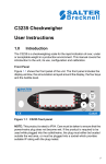
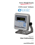
The Model 1080, shown in Figure 2.1,is an easy to use, uncomplicated, panel mount
indicator for weighing with the built-in capability to provide network controls and share
data via Ethernet, PROFIBUS and DeviceNet. It is ideal for tank weighing applications
providing process control interface and data management. These same features are
also available when used with applications using bench scales and floor scales. The
display includes annunciators for fast visual awareness for checkweighing. Also the
indicator can perform counting functions, peak weight functions, be an axle weigher
and act as a remote display for all Avery Weigh-Tronix E-series indicators.
Figure 2.1 Front panel of the 1080 indicator
In addition to connecting to network interfaces, the 1080 can connect to printers,
remote displays, computers and one SensorComm.
SensorComm available in North America only.
There are three setpoint control outputs and the indicator can accommodate three
remote switch inputs for Zero, Print, Tare, Units, F1, Start and Stop.
2.1
10
Specifications
Power Requirements:
9-36 VDC 5Amps
Climatic Environment:
-10 to + 40C, closed, non-condensing
EM Classification:
E2
Weight:
2.75 lb, 1.25kg
Dimensions:
6.06 inch W x 3.23 inch H x 5.82 inch D
(154mm W x 82mm H x 148mm D)
1080 Indicator User Instructions
3
Front Panel
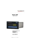
The front panel, shown in Figure 3.1, consists of the keys and display.
Never press a key with anything but your finger. Damage to the overlay may result if
sharp or rough objects are used.
Figure 3.1 Model 1080 front panel
There are seven keys on the front panel. Their functions are listed below.
Press the TARE key to perform a tare function. Also acts as a left arrow key when
in the menu structure.
Press the SELECT key to toggle between Gross, Net, Tare, Count, Gross
Accumulator, Net Accumulator, Transaction Counter, Piece Weight, and Peak.
Dependent on the current application. Also acts as an up arrow key when in the
menu structure. Press and hold to access the outputs menu.
Press the ZERO key to zero the display. Also acts as an Escape key when in the
menu structure.
Press the PRINT to send information to a peripheral device through the Comm
port. Also acts as a down arrow key when in the menu structure.
Press the UNITS key to scroll through the available units of measure while in
normal operating mode. Also acts as a right arrow key when in the menu structure.
Press the F1 key to select application specific choices. Also acts as an ENTER key
in the menu structure
Press and release the ON/OFF key to turn the unit on. Press and hold the key until
the unit turns off.
1080 Indicator User Instructions
11
Front Panel
3.1
Annunciators
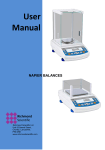
There are several annunciators around the edge of the display. Figure 3.2 explains
each one.
Figure 3.2 Annunciators.
12
Motion
Lights during scale motion. Goes out when scale is stable
Gross
Lights when gross weight is displayed
Net
Lights when net weight is displayed
Tare
Lights when tare weight is displayed
Print
Lights when print format sent through serial port
OP 1 (Under)
Lights when output one is activated or for Under condition during
checkweighing
OP 2 (Accept)
Lights when output two is activated or for Accept condition
during checkweighing
OP 3 (Over)
Lights when output three is activated or for Over condition during
checkweighing
Preset Tare
Lights when preset tare is active
Custom Unit
Lights when a custom unit of measure is active
Accumulator, Count
or Peak
Lights when an accumulation occurs and while in the count and
peak applications
Network &
SensorComm
Status
This is configurable to light to show status of the Network 1,
Network 2 or SensorComm. See the note following this table.
(SensorComm available in North America market only.)
LB
Lights when pounds is the active unit of measure
Center of Zero
Lights when weight on the scale is within the zero range
KG
Lights when kilograms is the active unit of measure
1080 Indicator User Instructions
3.2
Numeric Entry Procedure
Far Right LED color
(Chosen as SCOM or Network in configuration. Can’t be both.) SCOM:
Red – a cell has been ghosted. Check the ghost log.
Green – a sensorcomm error has occurred. Check the error log.
Off – Scale is functioning normally.
Network 1 or 2:
Red – A network error has occurred. Check the network settings on the indicator and
PLC, and reboot the indicator.
Green – The network connection has been established.
Amber – The network is ready for a connection, but no connection has been
established
3.2
Numeric Entry Procedure
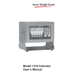
Some keys have alternate functions when you need to enter numbers. See Figure 3.3.
Figure 3.3 Alternate key functions
Press the ZERO key to terminate a value entry and leave the previous value, if any,
active
In screens where numeric entry is possible, choose the first digit using the SELECT or
PRINT keys. Use the TARE and UNITS keys to advance or backspace through the
entry. Press the F1 key to accept an entry. Below is an example:
Example: To key in the number 507:
Repeatedly press the SELECT or PRINT key until 5 appears on the display.
Press the UNITS key once to move cursor one space to the right.
Repeatedly press the SELECT or PRINT key until 0 appears on the display.
Press the UNITS key once to move cursor one space to the right.
Repeatedly press the SELECT or PRINT key until 7 appears on the display.
Press the F1 key to enter the value.
1080 Indicator User Instructions
13
Indicator Operations
4
Indicator Operations
The Model 1080 comes equipped with several weighing applications;
l
l
l
l
l
l
l
General weighing (default setting)
Accumulator weighing
Batch weighing
Checkweighing
Counting
Peak weighing
Split or Axle weighing
The 1080 can also perform as a remote display if so enabled. Ask your supplier for
information about setting up this indicator as a remote display.
These different applications are activated using a password protected menu. Contact
your local supplier for assistance with the password protected menu and enabling
applications.
The general weighing application comes as the default application. You can do gross
weighments, tare/net weighments and print a print format. Below are instructions for
each.
4.1
General Gross Weighing
To change unit of measure, press the UNITS key.
To perform gross weighing, power up the unit and follow these steps:
1.
Empty the scale and press ZERO key to zero the display…
0 is displayed.
2.
Place item to be weighed on the scale…
Weight is displayed.
4.2
General Tare/Net Weighing
To perform a net weighment, power up the unit and follow these steps:
1.
Empty the scale and press ZERO key to zero the display…
0 is displayed.
2.
Place item to be tared on the scale…
Weight is displayed.
14
1080 Indicator User Instructions
4.2
3.
General Tare/Net Weighing
Press the TARE key…
0 is displayed and the NET annunciator lights.
To clear a tare weight, remove all weight from the scale and press the TARE key.
4.
Place material to be weighed on the scale…
Net weight of material is displayed.
5.
Repeatedly press the SELECT key to scroll through gross, tare, and net
modes. Remove the weight from the scale and press TARE to return to gross
mode.
4.2.1 Using Outputs in the General Weighing Application
The output will trigger when weight goes above the target set for that output and will
remain on until the weight falls below the target. Follow these steps to configure three
outputs:
1.
With the indicator powered up, press and hold the SELECT key until…
OP1 is displayed.
2.
Press the PRINT key to set the value for the output…
Use the numeric entry procedure to key in a value, see note below, and
press the F1 key to accept the value. OP1 will be displayed
OR
Press the ZERO key to select the next output.
3.
Repeat step 2 for each output. Press ZERO key to select the next output and
then return to normal operation with the ingredients active.
Choose the first digit using the UP or DOWN keys. Use the LEFT and RIGHT keys to
advance or backspace through the entry.
Output operation in the general weighing application:
Below Configured Value:
Outputs are ON
Annunciators are OFF
TIU3 Relays are ON
Above Configured Value:
Outputs are OFF
Annunciators are ON
TIU3 Relays are OFF
1080 Indicator User Instructions
15
Indicator Operations
4.3
Accumulator Weighing
The accumulator is memory that collects individual weighments (gross and net) and
stores the totals. These totals can be recalled at any time. The number of weighments
included in the totals can be displayed and all information can be reviewed and deleted.
To use the accumulator, power up the unit and follow these steps:
1.
Empty the scale and press ZERO key to zero the display…
0 is displayed.
2.
Place item on the scale…
Weight is displayed.
You can use tare/net weighing with the accumulator application. The accumulator
stores both gross and net totals for later recall.
3.
Press the F1 key or PRINT key to add weight to the accumulator. Pressing the
PRINT key also prints the default print format …
A circle annunciator lights briefly on the right side of the display to show
the weight was accumulated.
4.
Remove weight from the scale. Weight must return to zero before another
accumulation can be recorded.
5.
Repeat steps 2 through 4 for each weighment you want to accumulate.
6.
To review the accumulator total and the number of weighments, remove all
weight from the scale and press the SELECT key repeatedly…
1st press =
Net weight displayed
2nd press = Tare weight displayed
3rd press = Display toggles between showing ACCUM. and gross total of all
weighments
4th press =
Display toggles between showing ACCUM. and net total of all
weighments
5th press =
Display toggles between showing TOTAL and number of
weighments
6th press =
Display returns to gross weigh mode
You must remove all weight from the scale to scroll through the items listed above.
With weight on the scale, repeatedly pressing the SELECT key will only show the
gross, net and tare values.
You need the supervisor’s password to clear the accumulator. See Supervisor Menu on
page 41
16
1080 Indicator User Instructions
4.3
Accumulator Weighing
4.3.1 Using Outputs in the Accumulator Application
If enabled, you can use the outputs function while in the accumulator application.
Outputs are enabled in a password protected menu. Contact your local supplier for
assistance with the password protected menu. Follow these steps to set up to three
Choose the first digit using the UP or DOWN keys. Use the LEFT and RIGHT keys to
advance or backspace through the entry.
Output operation in the Accumulator application:
Below Configured Value:
Outputs are ON
Annunciators are OFF
TIU3 Relays are ON
Above Configured Value:
Outputs are OFF
Annunciators are ON
TIU3 Relays are OFF
outputs:
1.
With the indicator powered up, press and hold the SELECT key until…
OP1 is displayed.
2.
Press the PRINT key…
The current value for OP1 is displayed.
3a.
Press the F1 key to accept the displayed value
OR
3b.
Key in a value using the numeric entry procedure, see note at left, and press
the F1 key.
OP1 is displayed.
4.
Scroll through all three outputs by using the TARE or UNITS key.
Repeat steps 2 and 3a or 3b for each output.
5.
Press ZERO key…
SAvE is displayed.
6.
Press the F1 key to save the changes or the ZERO key to abort the changes…
The unit returns to normal operation mode with the saved outputs active.
1080 Indicator User Instructions
17
Indicator Operations
7.
4.4
As you apply weight to the scale, output one will activate below its setpoint and
deactivate above its setpoint. The same is true for the other two setpoints.
Each output’s annunciator will light on the display when the output value is
reached.
Batch Weighing
This section applies if your indicator has the batching application active.
The batching application has a recipe with up to eight ingredients. In the recipe, the
following items are set.
Batch type can be by weight, percentage or gross. Each explained below.
Constant Weight
Batches are all the same size and the weight of each ingredient is
predetermined by the recipe.
Percentage
Batch size is chosen by the operator and each ingredient is
determined by the percentage set in the recipe.
Gross
Each ingredient runs until the gross weight on the scale reaches
the value that was set, regardless of the weight on the scale when
the batch was started.
After a batch has been started, it can be aborted by pressing the F1 key.
Batching mode can be Manual, Automatic, Filling, Reverse Filling or Continuous.
Manual
If the recipe is set up for manual mode, you press the F1 key to
start the batch and you need to press the F1 key each time a
setpoint is reached to activate the next ingredient output. See
important note below.
When in Manual Mode, you must press the F1 key during ingredient filling to abort the
operation. If you press F1 during a configured delay time, the key press is ignored. An
F1 press after the delay time will start the next ingredient.
Automatic
18
If the recipe is set up for automatic mode, you press the F1 key to
start the batch and each output is activated and deactivated
automatically by the indicator.
1080 Indicator User Instructions
4.4
Filling
Batch Weighing
In Fill mode, any recipe that has been setup is ignored. The filling
process is run based on the values set for the outputs. In order to
complete the filling process, at least one output must be enabled.
See the following note.
The batching modes, Filling and Reverse Filling, can be configured to operate in two
ways.
Absolute mode Setpoints activate when the F1 key is pressed. When the net
weight on the scale reaches the configured output value, the setpoint will deactivate.
Relative mode When the F1 key is pressed, the starting weight is captured and
the outputs activate. The output will not deactivate until the net weight on the scale
reaches the starting weight plus the configured output value.
See Batch Weighing on page 18 for information about setting these modes.
Reverse Fill
Continuous
In reverse filling mode, any recipe that has been setup is ignored.
The reverse filling process is run based on the values set for the
outputs. In order to complete the filling process, at least one output
must be enabled. See the previous note and the following
instructions:
1.
Press the F1 key to begin the reverse filling process.
2a.
If output one is enabled, and the net weight on the scale is
above the value of the output, output 1 will come on.
2b.
If output two is enabled, and the net weight on the scale is
above the value of the output, output 2 will come on.
2c.
If output three is enabled, and the net weight on the scale
is above the value of the output, output 3 will come on.
3.
Each output will remain on until its output value is met.
4.
The reverse filling process can be restarted by pressing
the F1 key.
Continuous batching mode. This mode is very close to the Auto
mode but, in continuous mode another batch is started
immediately after the previous batch has finished. In auto mode
the user must press the F1 key to start each batch.
The Basis of each ingredient can be weight or time.
Weight
If an ingredient basis is weight, the output activates at the
appropriate time and deactivates when the weight set in the recipe
is reached.
Time
If an ingredient basis is time, the output activates for the time set
in the recipe and then deactivates.
1080 Indicator User Instructions
19
Indicator Operations
In filling mode the process can be changed by changing the value(s) of the outputs.
Output operation in the Batching application:
Before activation by recipe:
Outputs are OFF
Annunciators are OFF
TIU3 Relays are OFF
After activation by recipe:
Outputs are ON
Annunciators are ON
TIU3 Relays are ON
Follow these steps to set up the three outputs:
1.
With the indicator powered up, press and hold the SELECT key until…
OP1 is displayed.
2.
Press the PRINT key…
The current value for OP1 is displayed.
3.
Press the F1 key to accept the displayed value (or ZERO to abort) or key in a
value and press the F1 key.
OP1 is displayed.
4.
Scroll through all three outputs by using the left and right arrow keys.
5.
Repeat steps 2 and 3 for each output.
6.
Press the ZERO key to exit the outputs setup.
7.
Press F1 to save the changes or the ZERO key to abort the changes
In automatic or manual mode, a recipe must be setup. The recipe values are set in a
password protected menu. However, a shortcut can be used to change the amount of
each ingredient.
Key legend reminder.
To access this shortcut menu:
1.
Press and hold the SELECT key until
ingr 1 is displayed
2.
Press the PRINT key to change the amount of ingredient 1 to batch.
A numerical value is displayed.
20
1080 Indicator User Instructions
4.4
Batch Weighing
3.
Scroll in a new value and press F1 or press the F1 key to accept the displayed
value. The UNITS and TARE keys allow you to access all 8 ingredients.
4.
When finished, press the ZERO key to escape from this menu.
Save will be displayed.
5.
To save the changes you made, press F1. To exit without saving, press the
ZERO key.
The batch type, batch mode, and ingredient basis cannot be changed through this
shortcut. Contact your local supplier for assistance in creating a recipe.
4.4.1 Auto Batching by Weight
Following is an example of batching for a recipe set as follows:
Batch type: Constant
Batch mode: Automatic
Basis:
Weight
1.
With the indicator powered up and the scale empty, zero the scale by pressing
the ZERO key…
0 is displayed.
2.
Press the F1 key…
The OP1 annunciator lights and output 1 is activated.
3.
Add weight to the scale…
When the weight reaches the setpoint for ingredient 1, OP1 annunciator
light goes out, OP2 annunciator lights and output 2 activates. See note
below.
Each ingredient may have a built in delay time between deactivation of one ingredient
and activation of the next.
4.
Add weight to the scale…
When the weight reaches the setpoint for ingredient 2, OP2 annunciator
light goes out, OP3 annunciator lights and output 3 activates. See the
note above.
5.
Add weight to the scale…
When the weight reaches the setpoint for ingredient 3, OP3 annunciator
light goes out and output 3 deactivates.
6.
1080 Indicator User Instructions
Empty the scale and repeat steps 1 through 5 for the next batch.
21
Indicator Operations
4.4.2 Manual Batching by Percentage
Following is an example of batching for a recipe set as follows:
Batch type: Percentage
Batch mode: Manual
Basis:
Weight
1.
With the indicator powered up and the scale empty, zero the scale by pressing
the ZERO key…
0 is displayed.
2.
Press the F1 key…
The OP1 annunciator lights and output 1 is activated.
3a.
Press the F1 key to accept the batch size
OR
3b.
Key in a new batch size, see note below, and press the F1 key…
The OP1 annunciator lights and output 1 is activated.
Choose the first digit using the UP or DOWN keys. Use the LEFT and RIGHT keys to
advance or backspace through the entry.
4.
Add weight to the scale…
When the weight reaches the percentage of the batch size set in the
recipe for ingredient 1, OP1 annunciator light goes out.
5.
Wait for the delay to elapse and then press the F1 key…
OP2 annunciator lights and output 2 activates.
6.
Add weight to the scale…
When the weight reaches the percentage of the batch size set in the
recipe for ingredient 2, OP2 annunciator light goes out.
7.
Press the F1 key…
OP3 annunciator lights and output 3 activates.
8.
Add weight to the scale…
When the weight reaches the percentage of the batch size set in the
recipe for ingredient 3, OP3 annunciator light goes out and output 3
deactivates.
9.
22
Empty the scale and repeat steps 1 through 8 for the next batch.
1080 Indicator User Instructions
4.5
4.5
Checkweighing
Checkweighing
The checkweighing annunciators are based off of net weight so if a tare is active only
the net weight is considered for checkweighing. If there is no tare, gross weight is
used as the basis for the annunciators.
This section applies if your indicator has the checkweighing application active.
Applications are activated through a password protected menu. Contact your local
supplier for assistance with the password protected menu.
Checkweighing allows a quick, visual check of the acceptability or unacceptability of an
item’s weight. See Figure 4.1.
Figure 4.1 Checkweighing annunciators
You set your target weight in one of two ways. It depends on how your indicator is
configured. The choice is made in the Supervisor menu. See TARGET application
(Checkweighing) on page 52
Your unit will be configured with limits mode or sample mode. Each are explained
below;
Limits Mode
Enter the upper and lower limits for the item and the indicator will
use those values to run the display.
Sample Mode
Place a correct weight “product” on the scale and press the F1
key. The indicator will use this weight to run the display. The
TARGET light stays lit if weight is within the upper and lower limits.
Directions for using each mode follows.
1080 Indicator User Instructions
23
Indicator Operations
4.5.1 Limits Mode: Entering Upper and Lower Limits
Choose the first digit using the UP or DOWN keys. Use the LEFT and RIGHT keys to
advance or backspace through the entry.
You can repeatedly press the SELECT key to view the items listed in the Sample and
Limits modes on this page.
Follow these steps to setup and use the checkweigher in limits mode:
1.
Empty the scale, press the ZERO key to zero the display, then press the F1
key…
Hi is displayed.
2.
Key in the upper weight limit using the numeric entry procedure. Press the F1
key to accept the value or the ZERO key to skip…
LO is displayed.
3.
Key in the lower weight limit using the numeric entry procedure. Press the F1
key to accept the value…
Place item(s) on the scale and the three left annunciator lights along the
top of the display will show if the weight is under, acceptable or over
based on the limits you have set.
You can repeatedly press the SELECT key to view the following from the gross weight
display:
1st press
Net annunciator lights and net weight is displayed.
2nd press Tare annunciator lights and tare weight is displayed.
3rd press Display toggles between HI and the upper weight tolerance, in the current
unit of measure.
4th press Display toggles between LO and the lower weight tolerance, in the current
unit of measure.
5th press Display returns to gross weighing mode.
4.5.2 Performing a Checkweighment in Limits Mode
1.
With your target weight set as described above, place your item on the scale…
If the weight is within the upper and lower tolerances you set, the second
annunciator from the left lights. If not, the first or third annunciator will be
lit.
2.
24
Repeat step 1 for all products of this weight.
1080 Indicator User Instructions
4.5
Checkweighing
4.5.3 Sample Mode: Using Product to Set Target Weight
Follow these steps to setup and use the checkweigher in sample mode:
1.
Zero the empty scale then place a sample of the correct weight on the scale…
Weight is displayed.
2.
Press the F1 key.
The weight is captured, the display reads 0 (net weight) and your
indicator is ready to use as a checkweigher. The target weight will be the
same as your sample item and the second annunciator from the left will
stay lit whenever an item’s weight is within the upper and lower
tolerances. By default this is ±1 division from the target weight.
You can repeatedly press the SELECT key to view the following from the gross weight
display:
1st press
Net annunciator lights and net weight is displayed.
2nd press Tare annunciator lights and tare weight is displayed.
3rd press Display toggles between HI and the upper weight tolerance, in the current
unit of measure.
4th press Display toggles between LO and the lower weight tolerance, in the current
unit of measure.
5th press Display returns to gross weighing mode.
4.5.4 Performing a Checkweighment in Sample Mode
1.
With your target weight set as described above, place your item on the scale…
If the weight is correct, 0 is displayed and the second annunciator from
the left lights. If the weight varies from the target value, first or third
annunciator will be lit and the weight will show a minus or plus weight
reading for the deviation from the target weight.
2.
Repeat step 1 for all products of this weight.
4.5.5 Using the Statistics Feature
If the statistical features are enabled, the user will be prompted to enter a sample size
after the High and Low limits are set.
The target application must be setup in LIMITS mode, see TARGET application
(Checkweighing) on page 52.
When the gross weight on the scale exceeds 10 divisions and the weight stabilizes, the
weight is captured and added to the statistical data. The gross weight on the scale must
return to the center of zero before another weighment can be captured.
The 1080 can operate in either Standard Deviation mode, X-bar/R mode or both modes
together.
1080 Indicator User Instructions
25
Indicator Operations
Standard Deviation Program
The Standard Deviation statistics option allows the 1080 in target mode to operate as
a standard checkweigher that provides a statistical summary of the weighing process.
It allows selecting the number of samples to be weighed, prints out each weighment,
or stores the weight data and prints out statistical analysis after the last sample
weighment.
This operation allows you to automatically print each weighment and the statistical
analysis or to store the weighments in memory and printout just the statistical analysis
without the weighments.
The printout of the statistical analysis contains the following information.
Sample Printout
Over tolerance
Under tolerance
Number of weights over tolerance
Number of weights under tolerance
Number of weights within tolerance
Average weight
Highest weight
Lowest weight
Standard Deviation
Coefficient of Variance (percent)
Number of samples taken
26
1080 Indicator User Instructions
4.5
Checkweighing
X-bar/R Program
The X-bar/R program is designed to weigh process samples, establish the average
weight, calculate the range between high and low weights, and the trend of deviation.
If the X-bar/R feature is enabled, the 1080 will keep a queue of the average weights of
the last 8 sample sets. This queue of averages is used to print trend information on the
statistical reports.
Trend Message
Meaning
1 of 1
The last average in the queue has an error greater than 3x the limit
2 of 3
Two of the last three averages in the queue have an error greater
that the limit.
4 of 5
Four of the last five averages have an error greater than the limit.
8 of 8
Eight of eight averages are on the same side of the target weight.
Example
With Weighments
Without Weighments
Over weight limit
Under weigh limit
X-bar/R= (Average Weight)
Range= (Range of Weights)
Trend Message
Weighments
Over weight limit
Under weigh limit
X-bar/R= (Average Weight)
Range= (Range of Weights)
Trend Message
1080 Indicator User Instructions
27
Indicator Operations
Clearing statistical data
The statistical information is cleared in the following situations:
l
If the X-bar/R feature is enabled, the statistical information is automatically
cleared when the sample size is reached even if the indicator is not
configured to print the report automatically.
l
If you press the PRINT key to print the report, you are prompted to clear the
information. If you press the F1 key when prompted, the statistical
information is cleared.
l
When the active PLU channel is changed, both the statistical data and the Xbar/R average queue are cleared.
l
When the over or under target values are changed, both the statistical data
and the X-bar/R average queue are cleared.
l
When the sample size is changed, both the statistical data and the X-bar/R
average queue are cleared.
l
If the indicator is configured to print reports automatically when the sample
size is reached, the statistical data is cleared after the report is printed.
4.5.6 Using Outputs in Checkweigher Application
If enabled, you can use the outputs function while in the checkweigher application.
Outputs are enabled in a password protected menu. Contact your local supplier for
assistance with the password protected menu. Follow these steps to set up to three
Choose the first digit using the UP or DOWN keys. Use the LEFT and RIGHT keys to
advance or backspace through the entry.
outputs:
Standard Outputs
1.
With the indicator powered up in normal checkweighing mode, press and hold
the SELECT key until…
OP1 is displayed.
2.
Press the PRINT key…
The current value for OP1 is displayed.
3a.
Press the F1 key to accept the displayed value
OR
3b.
Key in a value and press the F1 key.
OP1 is displayed.
4.
28
Scroll through all three outputs by using the left and right arrow keys.
1080 Indicator User Instructions
4.5
Checkweighing
5.
Repeat steps 2 and 3a or 3b for each output.
6.
Press ZERO key to exit the outputs setup.
7.
As you apply weight to the scale, output one will activate below its setpoint and
deactivate above its setpoint. The same is true for the other two setpoints.
Each output’s annunciator will light on the display when the output value is
reached.
Output operation in the Checkweigher application:
Outputs are OFF in gross zero band
Annunciators are OFF
TIU3 Relays are OFF
Outputs latch on for appropriate OVER, UNDER and ACCEPT
Annunciators are ON
TIU3 Relays are ON
4.5.7 Target Outputs
If outputs are configured for Target mode in the Supervisor menu, outputs will follow the
limits and accept values. This means there is no additional configuration required.
1080 Indicator User Instructions
29
Indicator Operations
4.6
Counting
This section applies if your indicator has the counting application active. Applications
are activated through a password protected menu. Contact your local supplier for
assistance with the password protected menu.
There are two types of sampling; bulk and dribble. These are selected in the same
password protected menu mentioned above.
Bulk sampling
In this sampling method you place the specified number of items
on the scale all at once (in bulk) and the scale automatically starts
to calculate piece weight and then shows the count.
Dribble sampling In this sampling method you can count out the specified number
of items onto the scale and when you are ready, press the F1 key
and the scale starts to calculate piece weight and then shows the
count.
Each method is described below.
4.6.1 Bulk Sampling
1.
In gross weight mode, press the F1 key…
A numeric value is displayed. This is the current sample size.
Choose the first digit using the UP or DOWN keys. Use the LEFT and RIGHT keys to
advance or backspace through the entry.
2a.
Accept the current sample size by pressing the F1 key.
OR
2b.
Enter a new sample size (see note at left) and press the F1 key…
ZEroin is briefly displayed. This shows the indicator is zeroing itself.
Add is then displayed.
3.
Place the correct sample size on the scale all at the same time.
If the sample meets the minimum sample requirements, Busy is briefly
displayed, followed by one of two possible outcomes:
a. If the weight is stable, the display will show the correct number of
parts on the scale and the green annunciator is lit.
b. If the sample was unstable, Abort is displayed and the display
returns to gross weight mode. Repeat steps 1 through 3 using a
larger sample size.
4.
30
Place the parts on the scale to be counted.
1080 Indicator User Instructions
4.6
5.
Counting
You can accumulate the counts and track the number of transactions by
pressing the PRINT key while in count mode. See Displaying Count
Information on page 32 about displaying this information.
The display is showing counts when the green annunciator, shown below, is lit.
4.6.2 Dribble Sampling
1.
In gross weight mode, press the F1 key…
A numeric value is displayed. This is the current sample size.
2a.
Accept the current sample size by pressing the F1 key
OR
2b.
Enter a new sample size (see note below) and press the F1 key…
Zeroin is briefly displayed. This shows the indicator is zeroing itself. Add
is then displayed.
Choose the first digit using the UP or DOWN keys. Use the LEFT and RIGHT keys to
advance or backspace through the entry.
3.
Place the correct sample size on the scale and press the F1 key. Busy is
briefly displayed, followed by one of two possible outcomes:
a. If the sample met the minimum sample requirements and stable, the
display will show the correct number of parts on the scale and the
green annunciator is lit.
b. If the sample size was not large enough or the weight was unstable,
Abort is displayed and the display returns to gross weight mode.
Repeat steps 1 through 3 using a larger sample size.
4.
Place the parts on the scale to be counted.
5.
You can accumulate the counts and track the number of transactions by
pressing the PRINT key while in count mode. See Displaying Count
Information below about displaying this information.
1080 Indicator User Instructions
31
Indicator Operations
If the piece weight of the item being counted is known, you can manually enter the
piece weight by keying in the weight with the keypad and pressing and holding the
SELECT key.
4.6.3 Displaying Count Information
You can scroll through the following information by using the SELECT key:
From count display press SELECT -
The word PiECE and the piece weight toggle on the display.
press SELECT -
The word Cnttot and count total toggle on the display.
press SELECT -
The word ToTAL and the total number of count transactions toggle
on the display.
press SELECT -
Gross annunciator lights and the gross weight is displayed.
press SELECT -
Net annunciator lights and the net weight is displayed.
press SELECT -
Tare annunciator lights and the tare weight is displayed.
press SELECT -
The counts display is shown again.
4.6.4 Using Outputs in the Counting Application
If enabled, you can use the outputs function while in the counting application. Outputs
are enabled in a password protected menu. Contact your local supplier for assistance
with the password protected menu. Follow these steps to set up to three outputs:
1.
With the indicator powered up, press and hold the SELECT key until…
OP1 is displayed.
2.
Press the PRINT key…
The current value for OP1 is displayed.
3a.
Press the F1 key to accept the displayed value (or ZERO to abort)
OR
3b.
Key in a value, see note below, and press the F1 key.
OP1 is displayed.
Output operation in the Counting application:
Below Configured Value:
Outputs are ON
Annunciators are OFF
TIU3 Relays are ON
Above Configured Value:
Outputs are OFF
Annunciators are ON
TIU3 Relays are OFF
32
1080 Indicator User Instructions
4.7
4.7
Peak Weighing
4.
Scroll through all three outputs by using the left and right arrow keys.
5.
Repeat steps 2 and 3a or 3b for each output.
6.
Press ZERO key to exit the outputs setup.
7.
As you apply weight to the scale, output one will activate below its setpoint and
deactivate above its setpoint. The same is true for the other two setpoints.
Each output’s annunciator will light on the display when the output value is
reached.
Peak Weighing
This section applies if your indicator has the Peak application active.
Only the highest stable weight applied to the scale is displayed in the Peak application
when the peak weight value is selected to be displayed. Peak weight is designated by
the green Peak LED annunciator. As a reminder that you are in peak mode, the green
annunciator remains lit. See illustration below.
1.
Add weight to the scale…
Weight is displayed.
2.
Remove weight…
Peak weight is displayed.
3.
To clear the peak value, be sure scale is empty and press the F1 key…
0 is displayed.
4.
Repeat steps 1 through 3.
5.
Press the SELECT key to cycle through Gross, Tare, Net and Peak.
4.7.1 Using Outputs
If enabled, you can use the outputs function while in the peak application. Outputs are
enabled in a password protected menu. Contact your local supplier for assistance with
the password protected menu. Follow these steps to set up to three outputs:
1.
With the indicator powered up, press and hold the SELECT key until…
OP1 is displayed.
1080 Indicator User Instructions
33
Indicator Operations
2.
Press the PRINT key…
The current value for OP1 is displayed.
3a.
Press the F1 key to accept this value or the ZERO key to abort
OR
3b.
Key in a value, see note below, and press the F1 key.
OP1 is displayed.
Choose the first digit using the UP or DOWN keys. Use the LEFT and RIGHT keys to
advance or backspace through the entry.
Output operation in the Peak application:
Below Configured Value:
Outputs are ON
Annunciators are OFF
TIU3 Relays are ON
Above Configured Value:
Outputs are OFF
Annunciators are ON
TIU3 Relays are OFF
34
4.
Scroll through all three outputs by using the left and right arrow keys.
5.
Repeat steps 2 and 3a or 3b for each output.
6.
Press ZERO key to exit the outputs setup…
7.
Press the F1 key to save the changes or the ZERO key to abort the changes.
8.
As you apply weight to the scale, output one will activate below its setpoint and
deactivate above its setpoint. The same is true for the other two setpoints.
Each output’s annunciator will light on the display when the output value is
reached.
9.
As weight is removed the displayed weight will remain unchanged due to being
in peak mode but the OP annunciators will go out as each output is reached.
1080 Indicator User Instructions
4.8
4.8
Split (Axle) Weighing
Split (Axle) Weighing
The Split (Axle) weighing function allows you to capture the weight of each of a
vehicle’s axles, print each axle weight and when finished, print a total axle weight.
The scale surface must fit between the axles for this application to work.
If this application is active, the following steps cover the general operation.
1.
When the scale is empty there will be a green light or signal device to let the
driver know they can drive the first axle onto the scale.
2.
As the weight rises above a minimum set during 1080 configuration, the traffic
light will turn red, signalling the driver to stop with the first axle fully on the
scale.
3.
When the weight stabilizes, the axle weight is captured and the weight
information for the axle is sent to a connected printer.
4.
After printing the information the 1080 will cause the signal or traffic light to
turn green. The driver should pull ahead to empty the scale briefly then pull the
next axle onto the scale.
5.
Repeat steps 2-4 for each axle to be weighed.
6.
When the preset time expires (no more axles to weigh) the total is printed and
the system is reset for the next truck.
1080 Indicator User Instructions
35
Communications
5
Communications
The Model 1080 provides an RS-232 output and a USB-to-Scale interface, via a virtual
Com Port, for data transmission to a peripheral device. Contact your local supplier for
assistance with RS-232 or USB interface connections.
The default serial port parameters are 9600 baud, 8 databits, no parity and 1 stop bit.
Stop bits for the serial communication are preset to 1 stop bit. This is not
configurable.
If your indicator has a peripheral device connected, from the gross/net weighing mode
press the PRINT key to transmit the selected output(s).
The PRINT annunciator will illuminate while data is transmitted and the data configured
to be printed will be output to the printer.
Following are the default print formats
Print Formats 1-8 are for the Zebra Thermal printer. See examples on the following
pages.
Print Formats 9-15 are for a standard ASCII characters for use with dot matrix printer.
Print Formats 9 & 10
G 123456 lb
{ACT}{DSP}{UN}<CR><LF>{EOS}
Accumulator (Print Format 11), Batching (12) and Checkweigher (13) all
use the following:
G 123456 lb
{ACT}{DSP}{UN}<CR><LF>{EOS}
Counting, Print Format 14
Piece Count:
48
Piece Count: {CNT}<CR><LF>{EOS}
Peak Print Format 15
123456 lb
{PWT} {UN}<CR><LF>{EOS}
Remote Display Print Format 16
G 123456 lb
{ACT} {DSP} {UN}<CR><LF>{EOS}
36
1080 Indicator User Instructions
5.1
Thermal Labels Print Formats
The following are the default print formats are for the corresponding “Mode” setting in
the serial port configuration menu.
17 Port 1 Enquire (HEX05)
18 Port 1 Broadcast
19 Port 1 RD4100
20 Port 2 Enquire (HEX05)
21 Port 2 Broadcast
22 Port 2 Remote display
23 default General Print format
24 default Axle Print format
G 123456 lb
{ACT} {DSP} {UN}<CR><LF>{EOS}
5.1
Thermal Labels Print Formats
Format 1, 2 & 3
Time
Date
G
Gross Weight
T
Tare Value
N
Net Weight
Format 1 label 1.25” Wide x 1.00” Long
Format 2 label 2.50” Wide x 4.00” Long
Format 3 label 4.00” Wide x 6.00” Long
Print Format 4, same as above with barcode.
Label Size:
2.50” Wide
4.00” Long
1080 Indicator User Instructions
37
Communications
Thermal Labels Print Formats
Print Formats 5, 6 & 7
Time
Date
PLU Totals Information
Gross Total Accumulator
Format 5 label 1.25” Wide x 1.00” Long
Format 6 label 2.50” Wide x 4.00” Long
Format 7 label 4.00” Wide x 6.00” Long
Print Format 8, same as above with barcode.
Label Size
2.50” Wide
4.00” Long
38
1080 Indicator User Instructions
6
Error Messages
The following are displays you may see if problems occur or if invalid operations are
attempted with your indicator:
Display
Description
Over-range weight.
Under-range weight.
The unit cannot perform a function.
Displayed while a key is pressed when attempting to
modify a sealed selection without edit privileges.
1080 Indicator User Instructions
39
Menu Mode
7
Menu Mode
The Model 1080 has two menus you can use to set up and test the indicator: the User
menu and the Supervisor menu. Both are explained below.
7.1
User Menu
The 1080 has a User menu you use to do the following:
l
l
l
l
l
l
1.
See software information
Perform ADC test
Perform a display test
Perform a button test
Perform a serial port test
Audit the number of configurations and calibrations performed
Access the User menu by pressing and holding the ZERO key for 3-5 seconds.
Release the key when…
PASS_ is displayed.
2.
Use the SELECT and PRINT keys to scroll in the User menu password = 111
and the F1 key. See note below. Figure 7.1 shows a flowchart of the User
menu items. Use the keys shown in the box in Figure 7.1 to navigate through
the menu and choose the items you want.
The User menu password is 111. You must key in the password within 10 seconds or
the display returns to normal operation mode.
Choose the first digit using the SELECT or PRINT keys. Use the TARE and UNITS
keys to advance or backspace through the entry.
40
1080 Indicator User Instructions
7.2
Supervisor Menu
Figure 7.1 User menu flowchart
For specific instructions on the User menu see Indicator Diagnostics on page 67.
7.2
Supervisor Menu
The Model 1080 has a Supervisor menu, shown in Figure 7.2, you use to do the
following:
l
l
l
l
l
Set time and date
Setup the various applications
View, print and clear logs and cal reports
Perform diagnostic tests
View audit counters
WARNING: Entering this menu and changing settings may affect operation of
the indicator and may require a service call to correct. Be sure you want to
change settings before doing so.
1080 Indicator User Instructions
41
Menu Mode
Figure 7.2 Supervisor menu
Password for the Supervisor menu is 1793.
42
1080 Indicator User Instructions
7.2
1.
Supervisor Menu
Access the Supervisor menu by pressing and holding the ZERO key for 3-5
seconds…
PASS_ is displayed.
2.
Scroll in the password, 1793 (see Numeric Entry Procedure on page 13) and
press the F1 key…
dAtE is displayed. Use this to set the current date.
7.2.1 DATE (Set date)
3.
From the dAtE display, press the PRINT key…
tYPE0 is displayed. Dates styles are listed below along with number you
enter to create that style:
0=MM/DD/YY
1=MM/DD/YYYY
2=DD/MM/YY
3=DD/MM/YYYY
See Figure 7.2 to reference the Supervisor’s menu.
While in a menu, the annunciator lights at the top of the display flash as a reminder.
4.
Scroll through the choices using the TARE or UNITS key and press the F1 key
to accept the displayed choice…
M XX is displayed. This stands for month.
5.
Scroll in the month number (01 for Jan., 02 for Feb., …12 for Dec) and press
the F1 key…
DD XX is displayed. DD stands for date and XX represents the current
value.
6.
Scroll in the date and press the F1 key…
YY XX is displayed. YY stands for year and XX represents the current
value.
7.
Scroll in the year (04=2004, etc.) and press the F1 key…
dAtE is displayed.
Key legend reminder.
1080 Indicator User Instructions
43
Menu Mode
7.2.2 HOUR (Set time)
1.
From the dAtE screen, press the UNITS key…
Hour is displayed. Set the time in this item.
2.
Press the PRINT key…
tYPE0 is displayed. Time can be in 24 hour or 12 hour styles. Time
styles are listed below along with number you enter to create that style:
0=HH:MM
1=HH:MM AM/PM
3.
Scroll through the choices using the TARE or UNITS key and press the F1 key
to accept the displayed choice…
HH XX is displayed. This stands for hour and its current value.
4.
Scroll in the hour based on the type of time you selected in step 2 and press
the F1 key. If you picked 0 (military time) in step 2, skip to step 5. If you picked
1 (AM/PM time) continue below…
P? yes or P? no is displayed. P? yes is for PM. P? no is for AM.
5.
Toggle between the choices using the TARE or UNITS key and press the F1
key to accept the displayed choice…
M XX is displayed. M stands for minute and XX represents the current
value.
6.
Scroll in the minute (see Numeric Entry Procedure on page 13) and press the
F1 key …
Hour is displayed.
7.2.3 SETUP (Setup menu)
1.
From the Hour display, press the UNITS key…
SEtuP is displayed. Use this submenu to print and/or clear application
reports, choose operation modes or values for applications which have
choices and view various function logs. Each is explained in the
following steps.
APP (Application submenu)
2.
From the SEtuP display, press the PRINT key…
APP is displayed. Each application is listed below this menu item.
Applications are enabled or turned on in a password protected menu the
user does not have access to but each application’s setup is done in this
area of the Supervisor menu.
44
1080 Indicator User Instructions
7.2
Supervisor Menu
PLU (Product Look Up)
3.
Press the PRINT key…
PLU is displayed. This stands for Product Look Up. This memory
channel contains all the parameter values and accumulator totals
associated with all the different applications. This menu item lets you
print out all the information in all the applications and/or clear it out.
The PLU report contains the following information for each of the 11 channels:
Channel #
ID #
Gross Accum.
Net Accum.
Count Accum.
Total
Tare Value
Lower Limit
Upper Limit
Piece Weight
Output Wt1
Output Wt2
Output Wt3
4.
Press the PRINT key…
Print is displayed. Use this item to print out a complete report of all
application parameters and totals.
5.
Press the PRINT key …
Port 1 or Port 2 is displayed. Use this item to select which port to use for
printing the report.
A USB device port is slaved to serial port #2. If port #2 is selected, data will be sent
via serial port 2 and USB.
6.
Toggle between Port 1 and Port 2 using the TARE or UNITS key. press the F1
key to accept the displayed choice…
The report is printed and the display shows bUSY briefly then returns to
Print.
7.
Press the UNITS key…
CLEAr is displayed. Use this item to clear all the information stored for
each application.
CAUTION! Only do this if you are sure you want the information permanently
removed!
You may want to print out the reports before clearing all the information.
See step 4 above.
1080 Indicator User Instructions
45
Menu Mode
8.
Press the PRINT key to clear all the information OR skip to step 9…
SuRE ? is displayed. This is asking if you are sure you want to clear the
information. If you are, press the PRINT key. If you do not want to clear
the data, press the SELECT key…
CLEAr is displayed.
9.
Press the SELECT key…
PLU is displayed.
ACC Application
1.
From the PLU display, press the UNITS key…
Acc. is displayed. This stands for the accumulator application.
See Figure 7.2 to reference the Supervisor’s menu.
2.
Press the PRINT key…
Print is displayed. Use this item to print out a complete report of
accumulator totals.
3.
Press the PRINT key …
Port 1 or Port 2 is displayed. Use this item to select which port to use for
printing the report.
A USB device port is slaved to serial port #2. If port #2 is selected, data will be sent
via serial port 2 and USB.
4.
Toggle between Port 1 and Port 2 using the TARE or UNITS key. press the F1
key to accept the displayed choice…
Display shows bUSY briefly then returns to Print.
5.
Press the UNITS key…
CLEAr is displayed. Use this item to clear all the information stored for
this application.
CAUTION! Only do this if you are sure you want the information permanently
removed!
You may want to print out the report before clearing all the information.
See step 2 above.
46
1080 Indicator User Instructions
7.2
6.
Supervisor Menu
Press the PRINT key to clear all the information OR skip to step 7…
SuRE ? is displayed. This is asking if you are sure you want to clear the
information. If you are, press the F1 key. If you do not want to clear the
data, press the SELECT key…
CLEAr is displayed.
7.
Press the SELECT key…
Acc. is displayed.
BATCH Application
1.
From the Acc. display, press the UNITS key…
bAtch is displayed.
2.
Press the PRINT key…
Print is displayed. Use this item to print out a complete report of recipe
information.
3.
Press the PRINT key …
Port 1 or Port 2 is displayed. Use this item to select which port to use for
printing the report.
A USB device port is slaved to serial port #2. If port #2 is selected, data will be sent
via serial port 2 and USB.
4.
Toggle between Port 1 and Port 2 using the TARE or UNITS key. Press the F1
key to accept the displayed choice…
Display shows bUSY briefly then returns to Print.
5.
Press the UNITS key…
rEciPE is displayed. Use this item to create a recipe.
6.
Press the PRINT key…
tYPE is displayed. Set the type of recipe; Constant, Gross, or
Percentage:
7.
ConSt
You set the weights for each ingredient and the batch
size is always the total of these ingredient weights.
GroSS
You set the gross weight at which each ingredient will
stop. The ingredient is complete when the gross weight
on the scale reads the value that was set, regardless of
the weight on the scale when the batch was started.
%
You set the percentage of a total batch for each
ingredient and you can pick a batch size and each
ingredient amount will be calculated automatically.
Press the PRINT key…
Current setting is displayed.
1080 Indicator User Instructions
47
Menu Mode
8.
Toggle between the choices by pressing the TARE or UNITS key. Press the F1
key to accept the displayed choice…
Your choice is selected and tYPE is displayed.
Key legend reminder.
9.
Press the UNITS key…
PrEAct is displayed. A preact is the time it takes an ingredient (which is
falling from an auger or other feeding device) to reach the scale after the
auger or feeder is shut off. There will always be material in “free-fall”
after an ingredient is shut off and the indicator will automatically
calculate this and update this value.
The first time a batch is run, overage for any ingredient weight is
calculated and the next time the ingredient is being weighed the output
will be shut down so approximately 70% of the overage is reduced. This
occurs each time a batch is run so that the system quickly learns and
produces accurate batches.
Under this item you can turn the preact on or off, or clear a current
preact.
10.
Press the PRINT key to set the preact…
on or oFF is displayed.
11.
Scroll through the choices (on, oFF, CLEAr) with the TARE or UNITS key.
Press the F1 key to accept the displayed choice…
PrEAct is displayed.
12.
Press the UNITS key…
Ingr X is displayed. X is the ingredient number. You have up to 8
ingredients for which you can set the following:
13.
bASIS
Set whether the ingredient is based on weight (Scale) or time
(Time).
SEtPt
Set the output you want associated with the ingredient. Choices
are 1, 2, 3 or None. Outputs must be enabled in a password
protected menu. Contact your local supplier for assistance with
the password protected menu.
dELAY
Set a time delay between when a basis is met and the next
ingredient action is started.
Press the PRINT key…
bASIS is displayed.
48
1080 Indicator User Instructions
7.2
14.
Supervisor Menu
Press the PRINT key…
The current setting is displayed; SCALE or TimE.
See Figure 7.2 to reference the Supervisor’s menu.
15.
Scroll through the choices with the TARE or UNITS key. Press the F1 key to
accept the displayed choice…
If you choose SCALE you are prompted to enter an ingredient weight. If
you choose TIME, your are prompted to enter a time value.
If SCALE is chosen for the basis, you can enter a negative weight to do an “unload.”
The selected output will activate until the entered amount of weight is removed from
the scale.
16.
Scroll in values using the numeric entry procedure and press the F1 key.
bASIS is displayed.
17.
Press the UNITS key…
SEtPt is displayed.
18.
Press the PRINT key…
1 is displayed. This stands for Setpoint 1.
19.
Scroll through the choices with the TARE or UNITS key. Press the F1 key to
accept the displayed choice…
SEtPt is displayed.
If you chose 1 this ingredient will use output #1. The same is true for the
2 and 3 choices. If you choose NONE, no output will be activated when
the ingredient is called by the recipe.
20.
Press the UNITS key…
dELAY is displayed.
21.
Press the F1 key…
The current delay value in seconds is displayed.
22.
Accept this value by pressing F1 or scroll in a new value using the numeric
entry procedure and press the F1 key…
dELAY is displayed. Repeat steps 12 through 22 for all the ingredients in
your recipe.
23.
Press the SELECT key twice…
rEciPE is displayed.
1080 Indicator User Instructions
49
Menu Mode
24.
Press the UNITS key…
ModE is displayed. Use this item to set the mode of the batching
application. Your choices are shown below.
25.
Auto
In auto mode, after the user begins the batching process the
indicator will activate the OP2 output when the weight for OP1 has
been reached. When the weight for OP2 is reached, OP3 will
activate. This happens with no intervention from the operator.
MAn.
In manual mode, after the user begins the batching process, the
user must press the F1 key to activate each subsequent output
after each output weight is reached.
Fill
In fill mode, any recipe that has been setup is ignored. The filling
process is run based on the values set for the outputs. In order to
complete the filling process, at least one output must be enabled.
Under this item you can choose one of the following:
abS
Setpoints activate when the F1 key is pressed. When the
net weight on the scale reaches the configured setpoint
value, the setpoint will deactivate.
rel
When the F1 key is pressed, the starting weight is
captured and the setpoints activate. The setpoint will not
deactivate until, the net weight on the scale reaches the
starting weight plus the configured setpoint value.
Cont
Continuous batching mode. This mode is very close to the Auto
mode, but in continuous mode, another batch is started
immediately after the previous batch has finished. In Auto mode,
the user must press the F1 key to start each batch.
rFill
Reverse Filling mode of operation. This mode is very similar to the
filling mode. However, the weight on the scale should be above
the configured setpoint weight when the F1 key is press in order
for the setpoint to be activated. When the weight on the scale
decreases enough to fall below the configured setpoint value, the
setpoint will deactivate. Under this item you can choose one of the
following:
abS
Setpoints activate when the F1 key is pressed. When the
net weight on the scale reaches the configured setpoint
value, the setpoint will deactivate.
rel
When the F1 key is pressed, the starting weight is
captured and the setpoints activate. The setpoint will not
deactivate until, the net weight on the scale reaches the
starting weight plus the configured setpoint value.
From the ModE display, press the PRINT key…
The current mode setting is displayed.
50
1080 Indicator User Instructions
7.2
Supervisor Menu
26a. Toggle between the choices by pressing the TARE or UNITS key. If you
choose Auto, MAn. or Cont, press the F1 key to accept the displayed choice.
ModE is displayed.
OR
26b. If you choose Fill or rFill you will see abS or rel. Toggle between the choices
by pressing the TARE or UNITS key. Press F1 to accept the displayed choice
and press the SELECT key…
ModE is displayed.
27.
Press the UNITS key…
CLEAr is displayed. Use this item to clear all the information stored for
this application.
CAUTION! Only do this if you are sure you want the information permanently
removed!
You may want to print out the report before clearing all the information.
See step 2 in this section.
28.
Press the PRINT key to clear all the information OR skip to step 29…
SuRE ? is displayed. This is asking if you are sure you want to clear the
information. If you are, press the F1 key. If you do not want to clear the
data, press the SELECT key…
29.
Press the UNITS key…
Print is displayed.
30.
Press the PRINT key…
Port 1 is displayed.
31.
Toggle between Port 1 and Port 2 using the TARE or UNITS key. Press the F1
key to accept the displayed choice…
The recipes and batch report will be printed.
A USB device port is slaved to serial port #2. If port #2 is selected, data will be sent
via serial port 2 and USB.
32.
Press the SELECT key…
bAtch is displayed.
1080 Indicator User Instructions
51
Menu Mode
TARGET application (Checkweighing)
Key legend reminder.
1.
From the bAtch display, press the UNITS key…
tArGEt is displayed. Use this item to print and clear reports for the
checkweigher application and to set the type of sampling to be used,
Limit or Sample.
2.
Press the PRINT key…
Print is displayed. Use this item to print out a complete report of
checkweigher information.
3.
Press the PRINT key …
Port 1 and Port 2 is displayed. Use this item to select which port to use
for printing the report.
A USB device port is slaved to serial port #2. If port #2 is selected, data will be sent
via serial port 2 and USB.
4.
Toggle between Port 1 and Port 2 using the TARE or UNITS key. Press the F1
key to accept the displayed choice…
Display shows bUSY briefly then returns to Print.
5.
Press the UNITS key…
tYPE is displayed. Use this to choose the mode of setting the target
weight for the checkweighing application: limit or SPL (sample)
6.
Press the PRINT key…
limit or SPL (sample) is displayed. See note below.
You do not set the limits in this menu. Limits are set in normal operation mode. This
menu item, tYPE, allows you to set the mode of choosing the target weight and limits.
Target outputs can only be reset when the scale returns to within the configured
Gross Zero Band. Gross Zero Band is configured in a password protected menu.
Contact your local supplier for assistance with the password protected menu.
limit
52
In this mode you enter the upper and lower limits for your item and
the indicator will use those values to run the display.
1080 Indicator User Instructions
7.2
SPL
7.
Supervisor Menu
In this mode you use a correct weight ‘product’ on the scale to set
the target weight. The indicator will use this weight to run the
display. After SPL is chosen, a number is displayed. This is the
sample tolerance. When a sample is done, the upper and lower
limits will automatically be ± (sample tolerance) divisions from the
target weight.
Toggle between the choices by pressing the TARE or UNITS key. Press the F1
key to accept the displayed choice…
tYPE is displayed.
8.
Press the UNITS key…
triPS is displayed. Use this to set outputs to follow over/under/accept or
to function as standard outputs.
9.
Press the PRINT key…
StndRd, tArGt 1 or tArGt 2 is displayed. Each is explained below:
10.
StndRd
Trips are configurable outputs. An output value can be
entered in weigh mode of operation.
tArGt 1
Latched outputs. When weight is added to the scale, the
appropriate trip; OP1, OP2 or OP3, activates. The trip is now
activated, and will remain active, until the scale returns to
gross zero.
tArGt 2
Unlatched outputs. When weight is added to the scale, the
appropriate trip; OP1, OP2 or OP3, activates. The trip will deactivate when weight decreases below the configured trip.
Scroll through the choices by pressing the TARE or UNITS key. Press the F1
key to accept the displayed choice…
triPS is displayed.
11.
Press the UNITS key…
CLEAr is displayed. Use this item to clear all the information stored for
this application.
CAUTION! Only do this if you are sure you want the information permanently
removed!
You may want to print out the report before clearing all the information.
See step 2 in this section.
12.
Press the PRINT key to clear all the information OR skip to step 25…
SuRE ? is displayed. This is asking if you are sure you want to clear the
information.
13.
If you want to clear the information, press the F1 key. If you do not want to
clear the data, press the SELECT key…
CLEAr is displayed.
1080 Indicator User Instructions
53
Menu Mode
14.
Press the UNITS key…
StAtS is displayed. This item lets you enable and set up the gathering of
statistical information.
15.
Press the PRINT key…
EnAbLE is displayed…
16.
Press the PRINT key to configure statistics…
One of the following is displayed:
nonE
No statistical features are enabled.
bar-r
The XBar-R feature is enabled.
Stdev The standard deviation feature is enabled.
both
17.
Both the Standard Deviation and XBar-R features are enabled.
Scroll through the choices by pressing the TARE or UNITS key. Press the F1
key to accept the displayed choice…
EnAbLE is displayed.
18.
Press the UNITS key…
Port is displayed.
The information printed depends on the statistical features that are enabled and the
type of printing that is enabled.
19.
Press the PRINT key…
Port 1 or Port 2 is displayed.
20.
Port 1
Choose this and statistical information will be sent out port #1.
Port 2
Choose this and statistical information will be sent out port #2 or
the USB port.
Toggle between the choices by pressing the TARE or UNITS key. Press the F1
key to accept the displayed choice…
Port is displayed.
21.
Press the UNITS key…
Print is displayed…
22.
Press the PRINT key…
Each of the three settings listed below can be enabled or disabled
individually.
button
54
Enable this item and a report of the data captured is printed
when you press the PRINT key. The information printed
depends on the features that are enabled. If this type of printing
is enabled, the user will be prompted to clear the statistical
information after the PRINT key is pressed to print the report.
Press the F1 key to clear statistical data.
1080 Indicator User Instructions
7.2
Supervisor Menu
each
Enable this item and each sample weight is printed as it is
captured. The range (under, over, accept) that the sample falls
into is also printed.
StAtS
Enable this item and a report of the data captured is
automatically printed when the sample size is reached. If this
type of printing is enabled, the statistical information will
automatically be cleared after the report is printed.
23.
Scroll through the three items in step 22 by pressing the TARE or UNITS key.
24.
Press the PRINT key to see the on/oFF choice for each. Toggle between the
choices by pressing the TARE or UNITS key. Press the F1 key to accept the
displayed choice…
Repeat for all three items in 22.
25.
Press the SELECT key three times to return to the…
tArGEt menu item.
1080 Indicator User Instructions
55
Menu Mode
COUNT Application
1.
From the tArGEt display, press the UNITS key…
Count is displayed. Use this item to clear and print reports for the count
application.
2.
Press the PRINT key…
Print is displayed. Use this item to print out a complete report of count
application information.
3.
Press the PRINT key …
Port 1 or Port 2 is displayed. Use this item to select which port to use for
printing the report.
4.
Toggle between Port 1 and Port 2 using the TARE or UNITS key. Press the F1
key to accept the displayed choice…
Display shows bUSY briefly then returns to Print.
5.
Press the UNITS key…
Min is displayed. Use this item to set the minimum sample weight as a
percent of capacity.
6.
Press the PRINT key…
Current value is displayed.
7.
Scroll in a percentage from 0-100% using the numeric entry procedure and
press the F1 key…
Min is displayed.
8.
Press the UNITS key…
SiZE is displayed. This is the sample size parameter. Use this to set the
sample size for the counting application.
9.
Press the PRINT key…
Current sample size is displayed.
10.
Use the numeric entry procedure to scroll in a new sample size. Press the F1
key to accept the displayed choice…
SiZE is displayed.
11.
Press the UNITS key…
ModE is displayed. Use this to select the sampling mode from these two
choices;
56
buLK
This is bulk sampling. In this method you place the specified
number of items on the scale all at once (in bulk) and the scale
automatically starts to calculate piece weight when the weight
stabilizes. The count is then displayed.
dribbL
This is dribble sampling. In this method you count out the
specified number of items onto the scale and when you are
ready, press the F1 key and the scale starts to calculate piece
weight and then shows the count.
1080 Indicator User Instructions
7.2
12.
Supervisor Menu
Toggle between the choices by using the TARE or UNITS key. Press the F1
key to accept the displayed choice…
ModE is displayed.
13.
Press the UNITS key…
CLEAr is displayed. Use this item to clear all the information stored for
this application.
CAUTION! Only do this if you are sure you want the information permanently
removed!
You may want to print out the report before clearing all the information.
See step 2 in this section.
14.
Press the PRINT key to clear all the information OR skip to step 15…
SuRE ? is displayed. This is asking if you are sure you want to clear the
information. If you are, press the F1 key. If you do not want to clear the
data, press the SELECT key…
CLEAr is displayed.
15.
Press SELECT…
Count is displayed.
TOP (Peak) Application
1.
From the Count display, press the UNITS key…
tOP is displayed. Use this item to clear and print reports for the peak
application.
2.
Press the PRINT key…
Print is displayed. Use this item to print out a complete report of peak
application information.
3.
Press the PRINT key…
Port 1 or Port 2 is displayed. Use this item to select which port to use for
printing the report.
4.
Toggle between Port 1 and Port 2 using the TARE or UNITS key. Press the F1
key to accept the displayed choice…
Display shows bUSY briefly then returns to Print.
5.
Press the UNITS key…
CLEAr is displayed. Use this item to clear all the information stored for
this application.
CAUTION! Only do this if you are sure you want the information permanently
removed!
1080 Indicator User Instructions
57
Menu Mode
You may want to print out the report before clearing all the information.
See step 2 above.
6.
Press the PRINT key to clear all the information OR skip to step 7…
SuRE ? is displayed. This is asking if you are sure you want to clear the
information. If you are, press the F1 key. If you do not want to clear the
data, press the SELECT key…
CLEAr is displayed.
7.
Press the SELECT key…
Top is displayed.
8.
Press the SELECT key…
APP is displayed.
LOGS (Log submenu)
9.
From the APP display, press the UNITS key…
LOGS is displayed. The Logs menu item allows you to view, print or
clear logs for the following:
Calibration
Overload and Underload Errors
SensorComm Errors
Ghost Errors
10.
Press the PRINT key…
CAL is displayed. You must print out this log to view it. Below is a
sample of a calibration log printout:
Calibration Log:
Time: 23:58
Date: 12/17/2003
Scale Serial#: 123456
Calibration Zero:
0.3456 mV/V
Calibration Span:
2.3455 mV/V @ 3000 lb
11.
Press the F1 key to print the report…
Port 1 or Port 2 is displayed. Use this to choose which port to print
through.
58
1080 Indicator User Instructions
7.2
12.
Supervisor Menu
Toggle between the port choices using the TARE or UNITS key and press the
F1 key to accept the displayed choice…
Report is printed and display returns to CAL.
13.
Press the UNITS key…
Err.LoG is displayed.
14.
Press the PRINT key…
oLoAd is displayed. This is the overload counter.
15.
Toggle between oLoAd and uLOAD (overload) by using the TARE or UNITS
key and press the F1 key to accept the displayed choice…
Under both oLoAd and uLOAD are choices to view the counter (Cntr) or
print (PRINT) the report.
16.
Toggle between Cntr and Print by using the TARE or UNITS key and press the
F1 key to accept the displayed choice…
If you chose Cntr, the overload or underload count will be displayed.
If you chose Print, you can choose the port to print through and press
the F1 key. The counter value for overload or underload will be printed.
Example:
Overloads:
0 overloads
00:00 on 00-00-00
Underloads:
0 underloads
00:00 on 00-00-00
17.
When you are done with the error log section, press the SELECT key
repeatedly until…
Err.LoG is displayed.
See the section SensorComm Errors to see the list of error codes.
The S-COM log only appears if the scale is configured as a SensorComm scale. The
Ghost log will only appear if ghosting is enabled.
18.
Press the UNITS key…
S-COM is displayed. This is the SensorComm error log. See a sample
below:
SensorComm Log:
Error #1: 15:00 on 12-17-03
Misc:
1080 Indicator User Instructions
59
Menu Mode
Overloads:
12 overloads
Last overload:
12:00 on 12-17-03
19.
Press the PRINT key…
Print is displayed.
20.
Press the PRINT key to print the report.
Port 1 or Port 2 is displayed. Use this item to select which port to use for
printing the report.
21.
Toggle between Port 1 and Port 2 using the TARE or UNITS key. Press the F1
key to accept the displayed choice…
Display shows bUSY briefly then returns to Print.
22.
Press the UNITS key…
CLEAr is displayed. Use this to clear the log from memory.
23.
Press PRINT to clear the log…
SuRE ? is displayed.
24.
Press the F1 key to clear the log…
CLEAr is displayed.
25.
Press the SELECT key…
S-COM is displayed.
26.
Press the UNITS key…
GHoST is displayed. This is the Ghost error log. See a sample below.
Ghost Log:
Ghost is not engaged.Time: 12:16
Date: 04-12-06
27.
Press the PRINT key…
Print is displayed.
28.
Press the PRINT key to print the report.
Port 1 or Port 2 is displayed. Use this item to select which port to use for
printing the report.
29.
Toggle between Port 1 and Port 2 using the TARE or UNITS key. Press the F1
key to accept the displayed choice…
Display shows bUSY briefly then returns to Print.
30.
Press the UNITS key…
CLEAr is displayed. Use this to clear the log from memory.
60
1080 Indicator User Instructions
7.2
31.
Supervisor Menu
Press PRINT to clear the log…
SuRE ? is displayed.
32.
Press the F1 key to clear the log…
CLEAr is displayed.
33.
Press the SELECT key…
GHoST is displayed.
34.
Repeatedly press the SELECT key until…
SEtuP is displayed.
This completes the Setup submenu of the Supervisor menu. You can
return to normal operation (step 35) or go to the next submenu item,
tESt, by pressing the UNITS key.
35.
Press the ZERO key to return to normal weighing mode. You will be prompted
to save the changes you’ve made. Press the ZERO key to abort any changes
made or press F1 to accept them and return to normal operating mode.
Key legend reminder.
7.2.4 TEST (Test menu)
1.
From the SEtuP display, press the UNITS key…
tESt is displayed. This menu lets you view indicator information and test
the display, keypad, serial ports, inputs and outputs.
ABOUT (Indicator information)
2.
Press the PRINT key…
About is displayed. Press the PRINT key then repeatedly press the
UNITS key to view the part number and revision level for the software
found in your indicator.
Press SELECT key to return to About.
ADC (Analog scale test)
3.
From the About display, press the UNITS key…
Adc is displayed. This is the mV/V output of the connected analog scale.
4.
Press the PRINT key…
The mV/V value is displayed. This value should increase as weight is
applied to the scale
1080 Indicator User Instructions
61
Menu Mode
5.
Press the SELECT key…
Adc is displayed.
DISP (Display test)
6.
From the Adc display, press the UNITS key…
diSP is displayed. This is the display test item.
7.
Press the PRINT key to perform a dynamic test of the display.
8.
Press the ZERO key to stop the dynamic test…
The display flashes a few more times then diSP is displayed.
BUTTON (Key test)
9.
From the diSP display, press the UNITS key…
button is displayed. This is the button test item.
10.
Press the PRINT key to perform a button test. Each key you press will be
reflected on the display screen to confirm the button is functioning correctly.
11.
Press the ZERO key to stop the button test.
button is displayed.
SERIAL (Serial port test)
12.
From the button display, press the UNITS key…
SEriAL is displayed. This is the serial test item.
13.
Press the PRINT key to access the serial test.
Port 1 is displayed.
14.
Jumper the transmit and receive lines on the serial port and press the PRINT
key…
The display should show PASS. If there is a problem the display will
show FAIL.
15.
Press the SELECT key…
Port 1 is displayed.
16.
Press the UNITS key…
Port 2 is displayed. Repeat steps 14 and 15 to test port 2.
17.
Press SELECT key…
SEriAL is displayed.
62
1080 Indicator User Instructions
7.2
Supervisor Menu
INPUT (Input test)
18.
From the SEriAL display, press the UNITS key…
InPut is displayed. This is the input test item.
19.
Press the PRINT key to access the test.
1 2 3 is displayed. 1 stands for input 1, etc.
20.
If you jumper pins 1 and 2 of the I/O connector on the bottom of the indicator…
1 becomes 0 until the jumper is removed.
To test input 2, jumper pins 1 and 3. 2 becomes 0 until the jumper is
removed.
To test input 3, jumper pins 1 and 4. 3 becomes 0 until the jumper is
removed.
21.
Press the SELECT key…
InPut is displayed.
OUTPUT (Output test)
22.
From the InPut display, press the UNITS key…
outPut is displayed. This is the output test item.
23.
Press the PRINT key to access the test.
1 is displayed. This stands for output 1.
24.
Press the PRINT key…
The display toggles between on and oFF. This will toggle the output off
and on. Monitor the output to see that it is turning off and on. Use a Trips
Interface Unit (TIU3) or other output device.
25.
Stop the test by pressing the SELECT key…
1 is displayed.
26.
Press the UNITS key…
2 is displayed.
27.
Repeat steps 23 - 25 for outputs 2 and 3…
28.
Press the SELECT key…
outPut is displayed.
OPTION
29.
From the outPut display, press the UNITS key…
oPtion is displayed. Under this item are these options you can test; Aout, SEnSor (if Sensorcomm is installed) and nEtS (networks). See the
instructions below.
1080 Indicator User Instructions
63
Menu Mode
A-OUT test
30.
From the oPtion display, press the PRINT key…
A-Out is displayed. This stands for the analog output test.
31.
Press the PRINT key…
A numeric entry screen is displayed.
32.
Scroll in a percentage between 0 and 100 and press the F1 key…
The analog output will put out that percentage of voltage. For example:
If you have output set from 0 to 10V and you scroll in a percentage of 25,
the analog output voltage should read 2.5 volts. You can continue to
scroll in other percentages, press the F1 key and check the analog
output voltage.
33.
When you are finished testing the analog output, press the F1 key…
A-Out is displayed.
SENSOR test
This test can be used to properly adjust the deadload of the scale. Each sensor
should have similar mV/V outputs if the physical load on the scale is equally
distributed.
34.
From the A-Out display, press the UNITS key…
SEnSor is displayed. Use this to test the function of each weight sensor
attached via SensorComm.
35.
Press the PRINT key…
1 is displayed.
36.
Scroll through the available weight sensor numbers by pressing the TARE or
UNITS key. Press the F1 key when the sensor you want to test is displayed…
mV/V output of the selected sensor is displayed.
37.
Apply weight to the scale to verify the mV/V level changes.
38.
Press the F1 key to exit the test…
Sensor number is displayed.
39.
Repeat steps 35 - 37 for each sensor you want to test.
40.
Press the SELECT key…
SEnSor is displayed.
NETS test
41.
From the SEnSor display, press the UNITS key…
nEtS is displayed.
64
1080 Indicator User Instructions
7.2
42.
Supervisor Menu
Press the PRINT key…
nEt 1 is displayed.
43.
Toggle between nEt 1 or nEt 2 using the TARE or UNITS key and press PRINT
when the network you want to view is displayed.
The first screen of network configuration information is displayed.
44.
Repeatedly press the PRINT key to view all the configuration information. The
display will return to nEt 1 or nEt 2 when you’ve seen all the information.
This completes the tESt submenu. Press the SELECT key until tESt is displayed and
then press the UNITS key to go to the Audit submenu
To return to normal weighing mode, press ZERO. If you press ZERO you will be
prompted to save any changes made. Press ZERO to abort any changes or press the
F1 key to save changes.
7.2.5 AUDIT (Audit counters) menu
The next section of the Supervisor menu is the AUDIT submenu. This menu lets you
view configuration and calibration audit counters. These counters cannot be changed,
only viewed.
Follow these steps to access each item in the AUDIT submenu:
CFG (Configuration audit counter)
1.
From the tESt display, press the UNITS key…
Audit is displayed.
2.
Press the PRINT key…
CFG is displayed. This stands for the Configuration audit counter. Use
this item to see how many times this indicator has been configured.
3.
Press the PRINT key…
A number is briefly displayed, then CFG is displayed. This is the number
of times this indicator has been configured.
CAL (Calibration audit counter)
4.
From the CFG display, press the UNITS key…
CAL is displayed. This stands for the Calibration audit counter. Use this
item to see how many times this indicator has been calibrated.
5.
Press the PRINT key…
A number is briefly displayed, then CAL is displayed. This is the number
of times this indicator has been calibrated.
6.
Press the SELECT key…
Audit is displayed.
1080 Indicator User Instructions
65
Menu Mode
This completes the AUDIT submenu and the Supervisor menu. Press the ZERO key to
return to normal weighing mode.
Key legend reminder.
66
1080 Indicator User Instructions
8.1
8
Indicator Diagnostics
8.1
Testing Indicator Functions
Testing Indicator Functions
The User menu lets you test various functions of the indicator. The User menu is shown
in Figure 8.1. Instructions for using the menu are found below.
Figure 8.1 User menu
1.
Access the User menu by pressing and holding the ZERO key for 3-5 seconds.
PASS_ is displayed.
2.
Key in the User menu password (111) and press F1.
tESt is displayed.
Choose the first digit using the UP or DOWN keys. Use the LEFT and RIGHT keys to
advance or backspace through the entry.
3.
Press the PRINT key.
About is displayed. Press the PRINT key then the UNITS key to view
the part number and revision level for the software found in your
indicator.
Press SELECT key to return to About.
1080 Indicator User Instructions
67
Indicator Diagnostics
4.
Press the UNITS key…
AdC is displayed. This is the mV/V output of the connected analog
scale.
5.
Press the PRINT key…
The mV/V value is displayed. This value should increase as weight is
applied to the scale
6.
Press the SELECT key…
AdC is displayed.
7.
Press the UNITS key…
diSP is displayed. This is the display test item.
8.
Press the PRINT key to perform a dynamic test of the display…
All parts of the display flash.
9.
Press the ZERO key to stop the test…
The display flashes a couple more times and then diSP is shown.
10.
Press the UNITS key…
button is displayed. This is the button test item.
11.
Press the PRINT key to perform a button test. Each key you press will be
reflected on the display screen to confirm the button is functioning correctly.
The ZERO key is excluded from this test. It is used to stop the testing and
return to the menu item
12.
Press ZERO key to stop the button test.
button is displayed.
13.
Press the UNITS key…
SEriAL is displayed. This is the serial test item.
14.
Press the PRINT key to access the serial test.
Port1 is displayed. If you jumper the transmit and receive lines on the
serial port and press the PRINT key, the display should show PASS. If
there is a problem the display will show FAIL.
15.
Press the SELECT key after checking the port function…
Port1 is displayed.
16.
Press the UNITS key…
Port2 is displayed. Repeat the test from step 14 to check the port.
17.
Press the SELECT key twice to exit the serial test.
SEriAL is displayed.
18.
Press the SELECT key…
tESt is displayed.
68
1080 Indicator User Instructions
8.1
19.
Testing Indicator Functions
Press the UNITS key…
Audit is displayed.
20.
Press the PRINT key…
CFG is displayed. This stands for the configuration audit counter.
21.
Press the PRINT key to see the number of times the configuration has been
altered on this indicator.
22.
Press the SELECT key…
CFG is displayed.
23.
Press the UNITS key…
CAL is displayed. This stands for the calibration audit counter.
24.
Press the PRINT key…
The number of times the indicator has been calibrated is displayed.
25.
Press the ZERO key twice…
26.
The display returns to normal operation mode.
This completes the User menu.
1080 Indicator User Instructions
69
Ethernet Industrial Protocols
9
Ethernet Industrial Protocols
9.1
Ethernet IP Explicit Messaging
9.1.1 AWTX Input Point Object (Data Out)
Class Code: 64 hex
Table 9.1
Class Attributes
Supported services for this
attribute (hex)
Data Type
NA
Table 9.2
Instance
Attributes
Supported services for this
attribute (hex)
03 (Value)
0E (Get_Attribute_Single)
Data Type
Instances
SINT, INT, DINT,
USINT, UINT, UDINT,
REAL (based on
network config in
indicator
17 - all enabled data
items in one message.
1-16 (”out” data item x
in indicator is bound to
instance x)
9.1.2 AWTX Output Point Object (Data In)
Class Code: 65 hex
Table 9.3
Class Attributes
Supported services for this
attribute (hex)
Data Type
NA
Table 9.4
70
Instance
Attributes
Supported services for this
attribute (hex)
03 (Value)
10 (Set_Attribute_Single)
Data Type
Instances
SINT, INT, DINT,
USINT, UINT, UDINT,
REAL (based on
network config in
indicator
17 - all enabled data
items in one message.
1-16 (”out” data item x
in indicator is bound to
instance x)
1080 Indicator User Instructions
9.2
9.2
Ethernet IP Implicit Messaging
Ethernet IP Implicit Messaging
9.2.1 AWTX Assembly Instance for PLC Configuration
9.3
Input:
100
Output:
112
Configuration:
128
ModBus/TCP
9.3.1 Starting Register Locations for PLC Configuration
Input Read Only
30001
Input Read/Write
40001
Output Read/Write 40101
Read only values are mirrored at the Read/Write location.
1080 Indicator User Instructions
71
Avery Weigh-Tronix USA
1000 Armstrong Dr.
Fairmont MN 56031 USA
Tel:507-238-4461
Fax:507-238-4195
Email: [email protected]
www.wtxweb.com
Avery Weigh-Tronix UK
Foundry Lane,
Smethwick, West Midlands,
England B66 2LP
Tel:+44 (0) 8453 66 77 88
Fax: +44 (0)121 224 8183
Email: [email protected]
www.averyweigh-tronix.com