1
F-20
TROUBLESHOOTING & REPAIR
F-20
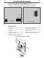
CONTROL TRANSFORMER (T2) VOLTAGE TEST (continued)
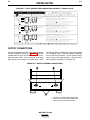
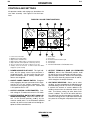
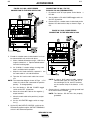
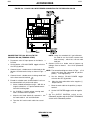
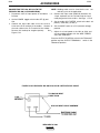
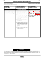
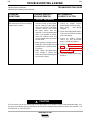
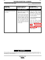
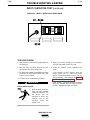
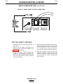
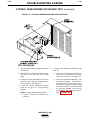
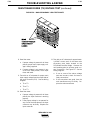
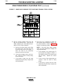
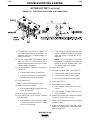
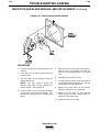
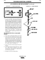
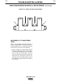
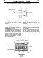
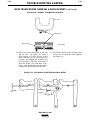
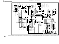
FIGURE F.4 – CONTROL TRANSFORMER X1 AND X2 TEST CONNECTIONS
RIGHT
SIDE VIEW
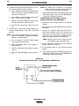
6. Test for 115VAC between leads X1 and
#231.
NOTE: If the main AC input supply voltage
varies, the control transformer voltage will
vary by the same percentage.
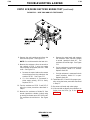
a. Connect one end of an insulated alligator clip to the X1 connection at the
input contactor (CR1) coil. See Figure
F.4.
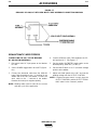
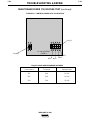
8. If 115VAC is not present between leads X1
and #231, check the spliced connection
between #231 and X2. Test for correct
main input supply power to the control
transformer primary windings (H1, H2, H3,
etc.). Check the main input supply power
hookup to the machine. See the Wiring
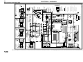
Diagram.
b. Connect the other end of the alligator
clip to one of the meter probes. Be
sure that neither the alligator clip nor
the meter probe touches any metal
surfaces.
c. Connect the other meter probe to the
#231 connection (top lead) at the
power switch. See Figure F4.
d. Apply input power to the DC-400.
7. Read the meter for 115VAC.
a. If 115VAC is present, the control transformer is functioning properly.
b. If 115VAC is NOT present, go to Step
8.
IDEALARC DC-400
LINCOLN
ELECTRIC
®
a. If the correct main input supply power
to the control transformer primary
windings is present AND the secondary
voltage is not correct, the control transformer may be faulty. Replace.