1
F-22
TROUBLESHOOTING & REPAIR
F-22
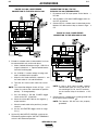
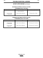
MAIN TRANSFORMER (T1) VOLTAGE TEST (continued)
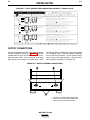
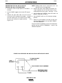
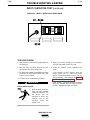
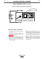
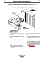
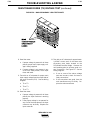
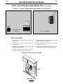
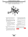
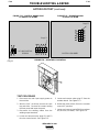
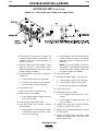
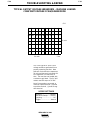
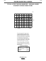
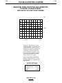
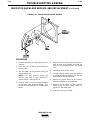
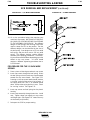
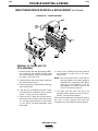
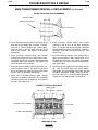
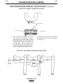
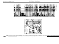
FIGURE F.5 – INPUT CONTACTOR, RECONNECT PANEL, AND PRIMARY LEADS
TO MAIN TRANSFORMER LOCATIONS
TEST PROCEDURE
1. Set the ON/OFF power switch to OFF.
2. Disconnect main input supply power from
the machine.
3. With the 5/16” nut driver, remote the case
top and sides and the reconnect panel
cover.
4. Inspect the input contactor, reconnect
panel, and primary leads to the main transformer for loose or faulty connections. See
Figure F.5.
5. Connect main input supply power to the
machine.
6. Set the ON/OFF power switch to ON.
a. Make sure the input contactor (CR1)
energizes and the fan runs.
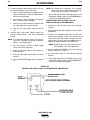
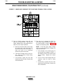
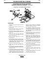
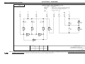
7. Test with an AC voltmeter for proper main
input supply voltage to the line side of the
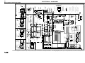
input contactor (CR1). See the Wiring
Diagram.
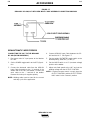
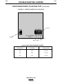
a. Confirm that the reconnect panel is
connected properly for the three-phase
main input supply power supplied to
the machine. See the reconnect panel
connection diagram located on the
inside of the input box assembly
access door.
IDEALARC DC-400
LINCOLN
ELECTRIC
®
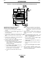
a. L1 to L2.
b. L2 to L3.
c. L1 to L3.