1
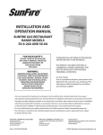
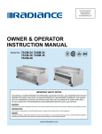
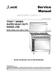
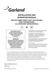
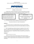
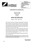
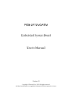
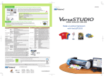
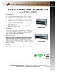
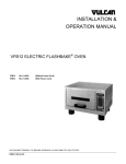
A Middleby Company
44 Lakeside Avenue, Burlington, VT 05401 USA
Telephone: (802) 860-3700
FAX (802) 864-0813
Website www.blodgett.com
INSTALLATION & OPERATION MANUAL
PHOENIX SERIES SUPER HEAVY DUTY RANGE LINE
MODEL SERIES BP, BPE, BPM, BPP, BPSB, BPCM, BPSHI & BPBB
Please read this manual completely before attempting to install or operate
this equipment. Notify carrier of damage. Inspect all components immediately.
RETAIN THIS MANUAL FOR FUTURE REFERENCE.
P/N 3000012219 REV. A
Page 1
IMPORTANT FOR YOUR SAFETY
THE INSTALLATION INSTRUCTIONS CONTAINED HEREIN ARE FOR THE USE OF QUALIFIED
INSTALLATION AND SERVICE PERSONNEL ONLY. INSTALLATION OR SERVICE BY OTHER
THAN QUALIFIED PERSONNEL MAY RESULT IN DAMAGE TO THE UNIT AND/OR INJURY TO THE
OPERATOR. Qualified installation personnel are individuals, a firm, corporation, or company which either
in person or through a representative are engaged in and are responsible for:
A. The installation or replacement of gas piping or the connection, installation, repair or servicing of
equipment, who is experienced in such work familiar with all precautions required and have complied
with all requirements of state or local authorities having jurisdiction. Reference: National Fuel Gas
Code, ANSI Z223.1, section 1.4, latest addendum. Or National Gas – Profane Installation Code CSA
B149.1 as applicable.
B. The installation of electrical wiring from the electric meter, main control box or service outlet to the
electric appliance. Qualified installation personnel must be experienced in such work, be familiar with
all precautions required and have complied with all requirements of state and local authorities having
jurisdiction. Reference: National Electric Code, ANSI/NFPA No. 70, latest addendum.
BLODGETT PHOENIX SERIES RANGES MUST BE INSTALLED IN ACCORDANCE WITH LOCAL
CODES, OR IN THE ABSENCE OF LOCAL CODES, WITH THE NATIONAL FUEL GAS CODE, ANSI
Z223.1, LATEST ADDENDUM, INCLUDING:
The appliance and its individual shutoff valve must be disconnected from the gas supply piping system
during and pressure testing of that system at test pressures in excess of ½ psig (14"WC /3.45 kPa).
The appliance must be isolated from the gas supply piping system by closing its individual manual shutoff
valve during any pressure testing of the gas supply piping system at test pressures equal to or greater
than ½ psig (14" WC/3.45 kPa).
POST IN A PROMINENT LOCATION THE INSTRUCTIONS TO BE FOLLOWED IN THE EVENT THE
SMELL OF GAS IS DETECTED. THIS INFORMATION CAN BE OBTAINED FROM THE LOCAL GAS
SUPPLIER.
WARNING
IN THE EVENT OF POWER FAILURE, DO NOT ATTEMPT TO OPERATE THIS DEVICE.
IMPORTANT
IN THE EVENT A GAS ODOR IS DETECTED, SHUT DOWN UNITS AT MAIN SHUT OFF
VALVE AND CONTACT THE LOCAL GAS COMPANY OR GAS SUPPLIER FOR SERVICE.
FOR YOUR SAFETY
DO NOT STORE OR USE GASOLINE OR OTHER FLAMABLE VAPORS OR LIQUIDS IN THE
VICINITY OF THIS OR ANY OTHER APPLIANCE.
WARNING
IMPROPER INSTALLATION, ADJUSTMENT, ALTERATION, SERVICE OR MAINTENANCE
CAN CAUSE PROPERTY DAMAGE, INJURY OR DEATH. READ THE INSTALLATION,
OPRATING AND MAINTENANCE INSTRUCTIONS THOUROUGHLY BEFORE INSTALLING,
OPERATING OR SERVICING THIS EQUIPMENT
P/N 3000012219 REV. A
Page 2
INTRODUCTION
Unpacking / Initial inspection
This appliance was inspected before leaving the factory. After unpacking, inspect the
unit for any damage that may have occurred during shipping. **The transportation
company assumes all responsibility for safe delivery. If the appliance is found to be
damaged, save all packaging materials and contact the carrier within 7 days of delivery.
Move the appliance as close as possible to installation location. Remove all boxes and
packaging material from inside of oven. Remove all shipping banding from pallet and top
of range. Remove all tops and oven components from their boxes.
General
Blodgett Phoenix ranges are manufactured for use with natural or propane gas. The gas
type for each range and the BTU rate is listed on the name plate. Verify the unit is for the
correct gas type before installing it, by reading specifications on appliance rating plate.
Please read the installation instructions carefully. Proper installation is essential for safe
and trouble free operation of this appliance.
Rating Plate Location
Remove the kick plate. The data plate is located to the right of center (behind the kick
plate) beneath the oven door. If gas orifices or regulator types (gas or propane) are
changed in the field, the rating plate must be changed to reflect the new orifice or gas
type. All work should be performed by a licensed and qualified professional.
Figure 1: Rating Plate
Location
Locate appliance in an area that will make it easy to load and unload the oven and will
facilitate the movement of food orders. Read Ventilation Requirements in the Installation
portion of this manual before locating the appliance.
WARNING
THE EQUIPMENT AREA MUST BE KEPT FREE AND CLEAR OF COMBUSTIBLE
MATERIALS.
P/N 3000012219 REV. A
Page 3
GENERAL RANGE SPECIFICATIONS
PHOENIX Oven Specifications
Model
Width
Height
Depth
Standard Oven
28-1/4"
(71.75 cm)
14"
(35.56 cm)
27-3/4"
(70.48 cm)
Convection Oven
28"
(71.12 cm)
13-3/4"
(34.92)
24-1/2"
(62.23 cm)
Convection ovens are provided with 1/4 HP 115 Volt 60HZ 1-Phase Blower Motor
P/N 3000012219 REV. A
Page 4
GAS BURNER BTU SPECIFICATIONS
MODEL/Feature
BTU
NOTES
Open burners
35,000 BTU per burner
Lift-Off octagon type
Manual griddle
T’stat controlled griddle
30,000 BTU per burner
25,000 BTU per burner
1 Every 12" of Griddle
width
Hot top
Robata/Satay
20,000 BTU per burner
25,000 BTU per burner
35,000 BTU per burner
12” wide full front to rear
18” wide full front to rear
2 IR burners per grid
section
French Top Range
30,000 BTU per burner
One for each top section
Charbroilers
15,000 BTU per burner
One Every 6" of Broiler
width
Standard oven
Convection Oven
35,000 BTU per burner
30,000 BTU per burner
Thermostat Adjustable from
150°F to 550°F
Gas Connections
Blodgett Phoenix ranges are supplied with a 1-1/4" front manifold and a 1" rear tailpipe.
For rear connection, remove cap. Ranges are supplied with 3/4" gas pressure regulator.
Operating pressure is 5.0" W.C. for natural gas or 10.0" W.C. for propane gas.
** Maximum incoming pressure is 14.0" W.C. (1/2 psi [3.45 kPa])
NOTE: Gas Pressure Regulator must be installed in an accessible “cool zone” protected
from grease and debris.
NOTE: Use a pipe joint compound that has been approved for use with liquefied
petroleum gases.
P/N 3000012219 REV. A
Page 5
INSTALLATION
HOOD AND VENTILLATION REQUIREMENTS
Combustion Air
This appliance should be installed in an environment capable of providing adequate
combustion air for the range. Phoenix range model features and the BTU ratings are
listed under GAS BURNER BTU SPECIFICATIONS table shown prior to this section.
Locate the particular model/features being installed and note the BTU output of the
features of each appliance, then add the BTU rate for all burners operating at once. IT IS
IMPORTANT THAT ADEQUATE COMBUSTION AIR BE PROVIDED FOR THE TOTAL
BTU CALCULATED. Avoid locating the appliance in a tightly confined area that is
incapable of providing sufficient combustion air. Clear space MUST be provided in front
of the appliance to allow for entry of combustion air.
Ventilation
An exhaust hood with code-approved fire controls and sufficient CFM exhaust must be
provided to remove excess heat/steam/grease, etc. from cooking. The hood canopy
must extend beyond all sides of the appliance. Refer to Standard NFPA No. 96 (latest
edition) for the removal of smoke and grease laden vapors from commercial cooking
equipment. Use the BTU listings under GAS BURNER BTU SPECIFICATIONS chart at
the beginning of this manual to calculate the total BTU, and then furnish exhaust air
CFM required. Room ventilation (make-up air) must be provided to compensate for air
being removed by exhaust system. Excessive negative room air pressure will result if
this is not done. Lack of exhaust and/or excessive negative pressure will interfere with
oven and pilot light operation and result in pilot outage, improper combustion, and poor
overall performance.
BATTERY INSTALLATION REQUIREMENTS
Ranges that are installed in a battery (two or more) must be aligned, leveled, with
manifolds leveled and connected to each other.
Care must be exercised in leveling all appliances to the same plane. This is important so
that the 1-1/4" gas manifolds located at the front of each appliance can be connected via
plumbing unions. Failure to level all appliances to the same plane will prevent the proper
interconnection of gas manifolds. If the manifolds do not line up from one appliance to
another, re-check the level and correct so that appliances are leveled to the same plane.
Install the first appliance in the position it will occupy in the battery. Align and level the
second appliance to it and connect gas manifolds together. Continue until all appliances
are installed.
CAUTION: Provisions for gas and electrical shut offs must be incorporated in the design
of the “battery” and accessible in the event the appliance is to be serviced.
CAUTION: All gas manifolds must align correctly to each other. Failure to provide proper
alignment can damage gas manifolds, pilots and gas valves.
P/N 3000012219 REV. A
Page 6
Adequate air supply must be provided for combustion air. Provide a minimum of 36" of
free space in front of all appliances. Provide adequate clearance for all air openings into
combustion chamber on all appliances.
Provide a gas regulator sufficient to supply adequate gas flow for the total BTU
requirement of all appliances that have connecting manifolds. Set gas regulators for 5.0"
W.C. for natural gas regulators and 10.0" W.C. for propane gas regulators.
Plate shelves and high shelves are adjustable and can be locked together with standard
3/8" bolts.
When installed and individually connected to the gas supply, each appliance must have
its own shutoff valve for servicing of the appliance.
ADJUSTABLE LEGS INSTALLATION
Raise the appliance above the floor. In the bottom plate of the appliance, locate the 5/8"
nuts that are welded into the bottom plate. Thread each of the legs into these nuts
tightly. Check that leg height adjustment operates freely.
OPTIONAL CASTERS INSTALLATION
Raise the appliance above floor. If legs are installed, remove them. Install casters by
threading caster bolts tightly into nuts that are welded into the bottom plate of the
appliance. If supplied, locking caster should be on the front side.
Locking
Lever
Figure 2: Caster Installation
CAUTION: Caster height is fixed and can’t be adjusted. If the floor is more than 1/4"
out of level over the span of a single appliance, 5/8” washers may be added in between
caster and bottom panel to level unit.
NOTE: When the appliance is to be installed with casters, gas connection must be made
with approved connectors for movable gas appliances (ANSIZ21.69-1987 and
addendum Z21.69189) with a quick-disconnect device approved for gas fuel.
(ANSIZ21.41-1989) In addition, a secure method of limiting the movement of the
appliance must be provided to protect the connector, gas line or any associated gas
piping from excess tension or being pulled from its connection. See Figure 3.
P/N 3000012219 REV. A
Page 7
CAUTION: This restraining device must always be in place when the appliance is in use.
If it is to be removed for cleaning purposes or to service the appliance, it must be reinstalled before the appliance is put back into service. Per ANSI regulations Z-21.69
(connectors), Z-83.11 (commercial gas ranges), Z-21.41 (quick-disconnect devices), with
latest revisions.
RESTRAINING DEVICE INSTALLATION
Figure 3: Restraining Device
(Must be installed when casters are used)
INSTRUCTIONS
This is a separate cable and should be less than 6" away from the gas connector in a
parallel orientation.
1.
Adjust cable clamps (1) so that cable length is 3" to 6" shorter than the
length of the gas connector including fittings.
2.
Secure eyelet plate to structurally sound attachment such as wall stud or
other solid attachment point.
3.
Attach the scissor hook to the staple and secure with cotter pin.
4.
Attach the spring hook to the gas appliance.
5.
** Check to make certain that the overall length of the restraining device is 3"
to 6" shorter than the overall length of the gas connector.
WARNING: Eyelet cable and all connections to wall and appliance must be
strong and secure enough to prevent appliance movement from pulling on gas
fitting in any way when the appliance is moved.
P/N 3000012219 REV. A
Page 8
HI-SHELF /RISER INSTALLATION
1.
Remove the existing riser from the unit.
2.
Slide the riser support assembly into the back of the appliance as shown in
the illustration below.
3.
Slide the riser support assembly toward the front of the range.
4.
Install the bolts through the slots with washers as shown.
5.
Tighten all bolts securely.
6.
Slide the stainless steel shroud over the riser support.
7.
Install rear panel and tighten securely.
8.
Install the flue diverter.
Assembly riser using
¼-20 Bolts and washers
Figure 4: Installing Hi-Shelf/Riser
MOUNTING SALAMANDER or CHEESEMELTER
CAUTION: Salamander (BP-SB model) and Cheesemelter (BP-CM model) models
require a “reinforced” riser for range mounting.
For the installation of a salamander or cheesemelter on the riser of a Phoenix range,
please refer to the Installation and Operation manual provided with the accessory unit.
Order the range mount and interconnect gas line kit (optional) to install these units.
P/N 3000012219 REV. A
Page 9
INSTALLATION CODES and STANDARDS
Installation of Phoenix series appliances must comply with all local and national building
codes for gas and electrical installations. Refer to standards ANSI Z233.1-1988 and
ANSI/NFPA 70-1990 or later for specifications. All installation or service work should be
performed by qualified personnel. (See explanation of qualified personnel at the
beginning of this manual).
ELECTRICAL INSTALLATION (convection models only)
WARNING: Electrical and grounding connections must comply with applicable
portions of the NATIONAL ELECTRICAL CODE ANSI/NFPA-70 (latest edition) and
local code requirements.
WARNING: The range must be electrically grounded in accordance with the
NATIONAL ELECTRICAL CODE and local code requirements.
For convection ovens, provide an electrical outlet capable of supplying 115 volts 60HZ 1
Phase for 1/4 HP blower motor. Blower motor amp draw is 4.4 amps/8 amp surge.
WARNING: This appliance is equipped with a three prong (grounding) plug for
user protection against shock hazard and should be plugged directly into a
properly grounded three prong receptacle. Do not cut or remove the grounding
prong from the plug.
CLEARANCES FROM COMBUSTABLE MATERIALS
Side
With 6" legs or 5" caters installed
4"
(10.16 cm)
Without 6" legs or 5" casters installed
4"
(10.16 cm)
Rear
2"
(5.08 cm)
2"
(5.08 cm)
Floor
6"
(15.24 cm)
0"
( 0 cm)
CAUTION: When appliance is installed without legs or casters, it must be set on a noncombustible curb or platform with a minimum front projection of 4 1/2" over the curb or
platform. Leveling bolts (5/8-11) can be used in the bottom frame of the range. If
plumbing and electrical connections allow, standard oven units can be installed flush to a
NON-COMBUSTABLE rear wall.
NOTE: Convection models are NOT recommended for curb or platform installations.
These models also require minimum 2” clearance at rear of unit
P/N 3000012219 REV. A
Page 10
Leveling
Appliances can be leveled with provided 6" high adjustable legs or in curb or platform
installations (with the legs/casters removed) using 5/8-11 leveling bolts. Attachment
points are located inside the body of the unit at the front and rear of the control box area
and inside the combustion area bottom on the right side of the inner body.
Adjust leveling legs or leveling bolts in base plate until the appliance is level left to right
and front to back. Re-check and re-level in both directions until the appliance is level in
all directions.
Gas Line and Regulator Installation
A gas pressure regulator is required for all installations. For single appliance
installations, a 3/4" regulator is supplied. Other size regulators are available as options
for larger pipe diameters. In all cases, the feed line should never be smaller than the
inlet pipe of the unit. For proper operation, the gas regulator should be installed
horizontally, in a accessible cool zone and protected from grease and debris. Install the
gas line with an individual shutoff valve for servicing and code requirements.
NOTE: In battery installations where a main gas feed is branched to multiple
appliances, pipe size and gas regulator should be calculated to provide a flow rate
sufficient for all burners on all appliances to operate simultaneously.
CAUTION: Do not use domestic flexible gas lines to install this product!
NOTE: Use a pipe joint compound that has been approved for use with liquefied
petroleum gases.
Gas Line Pressure Testing
If the gas system is pressure tested at any pressure equal to or greater than ½ psig (14"
WC/ 3.45 kPa), the appliance must be isolated from the system by closing the gas
shutoff valve. In Battery or Waldorf installations, each appliance must have its shutoff
valve closed.
GAS LEAK TEST
WARNING: Test all pipe joints for leaks before operating this appliance. This
includes all gas connections that may have loosened during shipment. Do not use
the appliance if any leaks are detected.
After gas connections are compete and tightened, use an approved liquid leak detector
or combination of liquid soap and water in a spray bottle to test all installed fittings.
Check for the smallest bubbles that can indicate a leak. Correct all leaks before
operation of the appliance.
WARNING! RISK OF FIRE, EXPLOSION, BODILY HARM, OR DEATH. Do not use an
open flame to check for leaks!
P/N 3000012219 REV. A
Page 11
BURNER FLAME ADJUSTMENTS
NOTE: All burner flames have been adjusted at the factory, occasionally onsite finetuning may be necessary, see below for proper burner flame adjustment.
Flame Characteristics for a Properly Adjusted Burner
A correctly adjusted burner produces a flame that makes contact with the burner and
makes the same contact all along or around the burner. It should be sitting on the burner
and should be dark blue at the bottom and light blue at the top. It should be steady, not
dancing or jumping (indication of too much primary air). This is true for both natural gas
fig. (7A) and LP gas. LP gas may exhibit light yellow tips fig. (7B). There are several
problems that can happen if the air and fuel mixture is not delivered to the burner
correctly fig. (7C).
Figure 7: Burner Flame Characteristics
Top Burner Pilot Adjustment
Locate the pilot adjustment screw as shown on the illustration below. Adjust the screw
until the pilot intersects the gas jets on burners.
Figure 8: Top Burner Pilot Light Adjustment
P/N 3000012219 REV. A
Page 12
Top Burner Adjustment
1.
Remove top burner control knobs.
2.
Remove front manifold cover plate
3.
Loosen the screw on the air shutter.
4.
Light the burners and observe the quality of the flame. Flame should be
sharp, well defined, two-tone blue as shown in Figure 7 (A).
5.
Adjust the air shutter as required.
6.
Tighten screw on the air shutter.
7.
Repeat procedure for all remaining burners.
8.
Replace burner knob
9.
Replace front manifold cover plate
NOTE: When using LP (liquid petroleum/propane) the flame may have a slight yellow tip,
however the yellow tip should be no greater than 10% the overall flame size as shown in
Figure 7 (B).
Figure 9: Top Burner Air Shutter Adjustment
P/N 3000012219 REV. A
Page 13
Oven, Griddle and Hot Top Burner Adjustment (Tubular Type Burners)
1. Remove kick plate (For oven). Remove front manifold cover (For Griddle/Hot
Tops
2. Loosen the screw on the air shutter.
3. Light the burner and observe the quality of the flame. Flame should be sharp,
well defined, two-tone blue as shown in Figure 7 (A).
4. Adjust the air shutter as required.
5. Tighten the screw on the air shutter, replace covers, knobs, panels as
required.
NOTE: When using LP (liquid petroleum/propane) the flame may have a slight yellow tip,
however the yellow tip should be no greater than 10% the overall flame size as shown in
Figure 7 (B).
Adjustment
Screw
Sleeve type
air shutter
Figure 10: Tubular Burner Air Shutter Adjustment
P/N 3000012219 REV. A
Page 14
OPERATION
Top Burner Controls
To include, but not limited to:
•
•
•
•
•
Open Burners
Hot Top Burners
French Top Burners
Manual Griddle Burners
Char Broiler Burners
Figure 9 (a): Conventional Top Controls
Figure 9 (b): Thermostatic Top Controls
Range Top Controls
1. Check that pilot lights are lit.
2. Turn valve to ON position. (Burner will light)
3. Adjust flame to desired height. (See Figure 7)
4. To turn off, move control to the OFF position.
P/N 3000012219 REV. A
Page 15
Broiler Top Controls
1. Check that pilot lights are lit.
2. Turn valve to ON position. (Burner will light)
3. Adjust flame to desired height. (See Figure 7)
4. To turn off, move control to the OFF position.
Griddle Top Controls (Conventional Controls)
1. Check that pilot lights are lit.
2. Turn valve to ON position. (Burner will light)
3. Adjust to desired heat. (See Figure 7)
4. To turn off, move control to the OFF position.
Griddle Top Controls (Thermostatic Control Option)
NOTE: Titan appliances with thermostatic griddle controls require special attention at
time of original set up.
1. Check that pilot lights are lit.
2. Turn valve to ON position. (Burner will light)
3. Adjust to desired temperature; allow 10-15 minutes for temperature to stabilize.
Temperature should be +/- 25 degrees of dial setting.
4. To turn off, move control to the OFF position.
Hot Top Range Controls
1. Check that pilot lights are lit.
2. Turn valve to ON position. (Burner will light)
3. Adjust to desired temperature.
4. To turn off, move control to the OFF position.
French Top Range Controls
1. Check that pilot lights are lit.
2. Turn valve to ON position. (Burner will light)
3. Adjust flame to desired height. (See Figure 7)
4. To turn off, move control to the OFF position.
P/N 3000012219 REV. A
Page 16
LIGHTING OVEN PILOT LIGHT
Standard Oven:
BEFORE LIGHTING PILOT LIGHT FOR OVEN LIGHT ALL PILOTS FOR TOP
BURNERS
1.
Remove the oven kick plate.
2.
Turn the oven gas valve to OFF.
Figure 16: Standard Oven Gas Valve Location
3.
Turn the oven thermostat to OFF.
4.
Push and hold down the red button on the pilot valve to light the pilot light.
Continue to hold down the red button for 30 seconds until the pilot light
remains on when the red button is released.
5.
If the pilot light goes out, repeat step 4. (In a new range installation this
procedure may have to be repeated several times until air is purged from gas
line.)
6.
Be sure oven door is closed.
7.
Turn the oven thermostat to desired temperature setting and turn the oven
gas valve to ON. Oven will light.
8.
Verify that the pilot light is still on.
9.
Turn oven gas valve to OFF.
10.
Reinstall the kick plate.
P/N 3000012219 REV. A
Page 17
Convection Oven
BEFORE LIGHTING PILOT LIGHT FOR OVEN LIGHT ALL PILOTS FOR TOP
BURNERS
1.
Remove the oven kick plate.
2.
Turn the master power switch to ON. (The light between the toggle switches
will glow indicating that the re-igniter is ON.)
3.
Turn the oven gas valve to OFF.
Figure 17: Convection Oven Gas Valve Location
4.
Turn the oven thermostat to OFF.
5.
Push and hold down the red button on the pilot valve, the electronic ignition
will light the pilot light. Continue to hold down the red button for 30 seconds
until the pilot light remains on when the red button is released.
6.
Be sure that oven door is closed.
7.
Set rocker switch to AUTO.
8.
Turn the thermostat to the desired temperature setting. Turn oven gas valve
to ON. The oven will light and the convection fan will run.
9.
Turn the oven gas valve to OFF.
10.
Verify that pilot light is still on.
11.
Reinstall the oven kick plate.
P/N 3000012219 REV. A
Page 18
Convection Oven Re-Igniter (electronic ignition)
NOTE: In order for the re-Igniter to operate, the master (power) switch located at the top
of the oven panel must be in the ON position.
If the pilot light is extinguished by drafts or temporary loss of gas pressure from air in
lines, the re-igniter will immediately attempt to re-light the pilot.
If the pilot fails to light, the thermocouple will cool (usually within 30 seconds) and shut
the gas off to the burner. This will require that the pilot light be re-lit manually.
Turn the oven gas valve to the OFF position. Wait 5 minutes. Then repeat steps 1-10
above to re-light pilot.
CONVECTION OVEN OPERATION
WARNING: The oven and its parts are hot. Use care when operating, cleaning, or
servicing the appliance.
1.
Turn on the master power switch.
2.
Turn the oven gas valve to ON.
3.
Set thermostat to the desired temperature.
4.
Turn fan switch to AUTO. (This will turn on the fan.)
5.
Allow oven to pre-heat to the desired temperature. (12-16 minutes.)
6.
Open oven door. (Fan will automatically stop.)
7.
Place product into oven leaving space all around for even heating.
8.
Close oven door. (Fan will turn on and oven will begin baking.)
NOTE: Placing the fan switch to MANUAL will allow the fan to run when the oven door is
opened to rapidly lower the oven temperature.
Convection Oven Controls
OVEN GAS
CONTROL
POWER ON
LIGHT
POWER
SWITCH
BLOWER
AUTO-MANUAL
SWITCH
OVEN
THERMOSTAT
P/N 3000012219 REV. A
Page 19
Power Switch
Master power switch for the convection oven.
Power ON Light
Light will illuminate when the oven is operating.
Blower Auto/Manual Switch
Toggle switch controls the mode for the blower.
AUTO – Normal mode. Allows for automatic operation of the blower. (Fan
shuts off when door is opened)
OFF – Turns the blower off. Used for limited cooking setting.
MANUAL – Used to rapidly cool the oven to accommodate cooking of
another product at a lower temperature setting. Or in the event of a door
switch failure fan will still operate but fan will stay on with door open
Oven Thermostat
This control is used to set the desired cooking temperature for the oven.
WARNING: The range parts are hot. Use care when operating, cleaning, or
servicing the range.
Lowering/Changing Oven Temperature:
In order to rapidly lower the oven temperature to accommodate another product, adjust
the thermostat to the new temperature, open the oven door and set the blower toggle
switch to MANUAL. The blower will operate and cool the oven very quickly, usually in a
few seconds.
When the oven has cooled, place the product into the oven, close the door and set the
blower toggle switch to the AUTO position.
Use of Oven without Blower Fan
It may be desirable for certain products (milk products, meringues, etc.) to turn off the
blower in order to allow the product to set. In these cases, the blower should not be
turned off for more than 2 or 3 minutes at a time.
NOTE: Use of the convection oven without the blower will not immediately damage the
oven but will reduce the lifespan of the blower motor, the efficiency of the oven, change
cooking times and create uneven heat distribution. It is recommended that the blower
be used whenever the oven is on.
WARNING: Do not operate the convection oven in the event of a power failure.
Control valves require electrical connection to operate.
P/N 3000012219 REV. A
Page 20
Care and Cleaning
The complete range should be given a periodic general cleaning. Lint and grease
suspended in the air will tend to collect in passages. Therefore, all flue ways, air
passages, and openings, burner ports, primary air openings, air shutters, etc. should be
periodically cleaned to prevent clogging.
WARNING: Range parts are hot. Use care when cleaning or servicing range top
and oven surfaces and burners.
Stainless Steel Surface
To remove dirt, grease or product residue from stainless steel, use an ordinary soap
solution. Dry thoroughly with a soft cloth.
To remove grease, food splatter and condensed vapors that have baked on the
appliance, apply cleanser to a damp cloth or sponge. NEVER RUB WITH A CIRCULAR
MOTION. To avoid marring the stainless steel finish, rub as gently as possible in the
direction of the grain lines of the stainless steel surface. Stubborn soil and burned-on
deposits can usually be removed with a Scotch-Brite ™ pad or stainless steel scouring
pad.
NOTE: Do not use ordinary steel wool, which will leave particles that will rust on the
stainless steel surface and further spoil the appearance of the finish.
CAUTION: Never use any metal tools including a wire brush, scouring pad (excluding
stainless steel), scrapper or file, which will permanently mar the stainless steel surface.
A marred stainless steel surface collects dirt more rapidly, is more difficult to clean and
increases the possibility of corrosion.
Darkened areas, called heat tint, may appear on stainless steel surfaces exposed to
excessive heat. Heat tint is caused by thickening of the protective surface of the
stainless steel and is not harmful. Heat tint can usually be removed by normal cleaning
procedures, but tint, which does not respond, requires vigorous scouring. Use a ScotchBrite™ pad or stainless scouring pad along with a powdered cleanser. Rub in the
direction of the stainless steel grain lines. Heat tint can be reduced by limiting exposure
of equipment to excessive heat during slack periods.
Oven Interior Cleaning
Frequent cleaning is required. Spills should be cleaned as soon as possible to prevent a
burned on condition called carbonizing. Allow the oven to cool before cleaning. A soap
or detergent solution is usually strong enough to remove any grease residue. Use a
mildly abrasive nylon cleaning pad for stubborn, stuck-on spills and stains. Use a noncaustic commercial oven cleaner when necessary, but do not allow it to come in contact
with the temperature probe. **Be sure to follow directions of the cleaning product being
used and wipe off all oven cleaner residues.
P/N 3000012219 REV. A
Page 21
Convection models
Grease should not be allowed to build-up on fan blower, also the vent openings of the
motor (located in the rear) must be kept clean using a stiff bristle brush and/or vacuum
Open Top Section
DAILY: Allow surfaces to cool and wipe top with burlap or other grease absorbing
material to remove spills and grease before they burn on.
WEEKLY: Allow surfaces to cool and wash open top section with a solution of washing
soda and water. Remove and wash drip pan under burners. Brush burner head with a
stiff wire brush. Clean clogged ports with a stiff wire or ice pick. Remove excessive
grease build up from burners by soaking in a solution of washing soda. Dry burners by
inverting them on an oven rack at a low temperature.
NOTE: Make sure the air shutters remain intact and in the same position as when the
burners were removed from the appliance.
Hot Top / French Top Section
DAILY: Allow surfaces to cool and wipe top with heavy burlap or steel wool and rub
briskly until clean. In order to clean all flanges and under lid, lift rings and plates.
WARNING: Never pour water on a HOT French Top/Hot Top section as water can
splash and/or intense steam can cause severe burns.
Griddle Section
DAILY: During use, scrape surface with the flat edge of spatula or metal scraper to
remove encrusted material. Wipe frequently with heavy absorbent cloth. Allow surface to
cool and polish with soft griddle stone or a high-grade grill pad. The griddle may be
washed with a cleanser and warm water, which will not crack the steel plate.
WARNING: Never pour water on a HOT griddle as water can splash and/or intense
steam can cause severe burns.
To oil the griddle, use a hydrogenated shortening. Never use salad oils, margarine or
butter, which cannot withstand temperatures greater than 300ºF.
Service
When service is required, contact your local Blodgett Authorized service company. To
find a Blodgett Authorized service company, go to www.blodgett.com and click on
service locator. You may also contact your dealer or the factory to perform mechanical
maintenance and repair. All mechanical maintenance procedures can be found in the
P/N 3000012219 REV. A
Page 22
Service Manual and must be performed only by Authorized service personnel. The
appliance should be inspected on an annual basis by an authorized service technician.
Any replacement of parts especially, gas control parts such as main burner valve or
thermostat should be an OEM factory part only.
Service/Maintenance Intervals
In order to provide maximum performance and longevity, this appliance must be
serviced regularly. Frequency of service largely depends on usage see below:
HOURS IN SERVICE
18-24 hours a day
12-18 hours a day
8-10 hours a day
4-6 hours a day
NUMBER OF DAYS
7 days a week
7 days a week
5 days a week
5 days a week
*RECOMMENDED INTERVAL
Every 30 days
Every 60 days
Every 120 days
Every 180 days
NOTE: All commercial appliances must be serviced at least once a year.
* - This schedule is not meant to imply that a service company needs to be hired at the
recommended intervals. Someone with basic mechanical knowledge (supervisor or
manager) should check and/or inspect the following:
•
•
•
•
•
•
Knobs/Dials – Make sure that they turn easily and are not seized.
Verify the burners are clean and light/burn properly
Check that moving parts operate freely
Look for grease, oil or debris buildup
Check thermostats for correct temperature
Verify that the racks, panels, guides are covers are installed and operating
properly.
If any of these items are found to be incorrect, malfunctioning or in need of attention,
contact an authorized servicer to repair or correct the issue (See SERVICE section to
locate a Blodgett Authorized service company).
In order to provide maximum performance, proper operation and to insure the safety of
the operator, all commercial appliances must be serviced at least once a year by an
authorized servicer. If for any reason the appliance has NOT been in use or has been
in storage, it is imperative that the appliance be inspected by a Blodgett Authorized
servicer prior to re-installation and/or operation.
NOTE: Most Blodgett Authorized servicers offer a scheduled maintenance program that
can be customized to the particular operation. Contact the servicer nearest you for
details.
P/N 3000012219 REV. A
Page 23
WARNING
If not installed, operated and maintained in accordance with the manufacturer’s
instructions, this product could expose you to fuel or fuel combustion substances,
which can cause death or serious illness and which are known to the State of California
to cause cancer, birth defects or other reproductive harm.
The State of California enacted the California Safe Drinking Water and Toxic Enforcement Act
of 1986, (Prop. 65), which “prohibits any person in the course of doing business from knowingly
and intentionally exposing any individual to a chemical known to the State of California to cause
cancer or reproductive toxicity without first giving clear and reasonable warning to such
individuals.” The Governor’s Scientific Advisory Panel added carbon monoxide to the list of
hazardous chemicals known to cause reproductive harm.
In order to establish full compliance with Proposition 65, a yellow warning label has been
attached to each gas-fired unit manufactured by Blodgett.
Carbon monoxide would not be present in concentrations that would pose a “significant risk” to
the consumer when the equipment is installed, operated and maintained as follows:
1. Installed in accordance with all local codes, or in the absence of local codes, with the
current National Fuel Gas Code ANSI Z223.1 Latest Addenda.
2. Installed under a properly designed and operating exhaust hood.
3. Connected to the type of gas for which the unit is equipped.
4. Proper appliance pressure regulator installed on the gas supply line and adjusted for the
manifold pressure marked on the rating plate.
5. Adequate air supply to the unit.
6. The equipment is operated in the manner intended and using the proper utensil for that
type of appliance.
7. Keep the equipment clean and have it checked periodically.
8. Burner air adjustments, mechanical maintenance and repairs must be performed by
qualified service personnel.
WARNING:
If the equipment is not installed, operated and maintained in accordance
with the above requirements, concentrations of carbon monoxide in excess of the
established limits could be present in the kitchen environment.
** ALL PERSONNEL IN THE WORKPLACE WHO MAY BE SUBJECT TO ANY
EXPOSURE OF CARBON MONOXIDE MUST BE WARNED OF SUCH POSSIBLE
EXPOSURE. THIS WARNING SHOULD BE CONVEYED IN A MANNER SO THAT IT
IS CLEARLY UNDERSTOOD BY THE EMPLOYEE. THE EMPLOYEE MUST BE
ASKED IF IN FACT HE OR SHE UNDERSTANDS THE CORRECT METHOD OF
OPERATION OF THE EQUIPMENT AND THAT A RISK OF EXPOSURE EXISTS IF
THE EQUIPMENT IS OPERATED IMPROPERLY.
P/N 3000012219 REV. A
Page 24