1
CENTRAL AIR CONDITIONERS
DC INVERTER MULTI VRF SERVICE MANUAL
T1/R410A/50Hz
( GC201107 - )
CONTENTS
PRODUCT................................................................................................................... 2
1 MODELS LIST ......................................................................................................................... 2
1.1 Outdoor Unit ..................................................................................................................................... 2
2 NOMENCLATURE.................................................................................................................. 5
2.1 Nomenclature of Outdoor Unit........................................................................................................ 5
3 FUNCTION ............................................................................................................................... 5
4 PRODUCT DATA ..................................................................................................................... 6
4.1 Product Data of Outdoor Unit......................................................................................................... 6
5 PIPING DIAGRAM ............................................................................................................... 16
5.1 Piping diagram of GMV-Pdm224W/NaB-M,GMV-Pdm280W/NaB-M ..................................... 16
5.2 Piping diagram of GMV-Pdm335W/NaB-M,GMV-Pdm400W/NaB-M,GMV-Pdm450W/
NaB-M..................................................................................................................................................... 17
CONTROL................................................................................................................. 20
1 CONTROL OF THE UNIT.................................................................................................... 20
1.1 Concept of Integral Control of the Unit ........................................................................................ 20
1.2 Operation Flow Chart of the Unit.................................................................................................. 22
1.3 Operation Flow Chart of Outdoor Unit......................................................................................... 26
2 WIREDLESS REMOTE CONTROLLER .......................................................................... 28
2.1 Wiredless Remote Controller Y512................................................................................................ 28
2.2 Wiredless Remote Controller YB1FA ............................................................................................ 31
3 WIRED REMOTE CONTROLLER .................................................................................... 36
3.1 Wired Controller Z60351F,Z60151F,Z63351F,Z63151F............................................................... 36
3.2 Wired Controller XK02 .................................................................................................................. 38
4 REGIONAL CONTROLLER ............................................................................................... 42
4.1 Function............................................................................................................................................ 42
4.2 Operation View ................................................................................................................................ 43
4.3 Display View..................................................................................................................................... 44
4.4 Connection Between Controller and Unit .................................................................................... 45
5 SMART ZONE CONTROLLER .......................................................................................... 46
5.1 Function............................................................................................................................................ 46
5.2 Operation View ............................................................................................................................... 46
5.3 Display View.................................................................................................................................... 47
5.4 Network Topological Diagram........................................................................................................ 48
5.5 Installation and Debugging............................................................................................................. 49
5.6 Attachment ....................................................................................................................................... 53
6 CENTRALIZED CONTROLLER ....................................................................................... 54
6.1 Central Control ZJ7011 .................................................................................................................. 54
6.2 Centralized Controller CE51-24/E(M) .......................................................................................... 57
6.3 Connection Between Controller and Unit .................................................................................... 68
6.4 Case Study ........................................................................................................................................ 68
7 MONITORING SOFTWARE ............................................................................................... 84
7.1 Remote Monitoring System ............................................................................................................ 84
7.2 BMS System ..................................................................................................................................... 84
8 DETECTION CONTROL BOARD ...................................................................................... 85
8.1 Gate-control Function .................................................................................................................... 85
8.2 Working Process of Gate Control .................................................................................................. 85
8.3 Detection Control Board Interface Sketch is shown in Fig.2: ..................................................... 86
8.4 Products Parameters ...................................................................................................................... 86
8.5 Installation of Detection Control Board ....................................................................................... 86
INSTALLATION ...................................................................................................... 89
1 PRECAUTIONS FOR INSTALLATION............................................................................. 89
1.1 Precautions for Safety ..................................................................................................................... 89
1.2 Key Points of Installation................................................................................................................ 90
2 FLOW CHART OF INSTALLATION.................................................................................. 91
3 INSTALLATION OF OUTDOOR UNIT ............................................................................ 92
3.1 Hoisting of Unit ............................................................................................................................... 92
3.1 Installation of Outdoor Unit with Side Air Outlet........................................................................ 93
3.2 Selection of Installation Site ........................................................................................................... 93
3.3 Dimensions Data ............................................................................................................................. 94
3.4 Clearance Data................................................................................................................................. 95
3.5 Take Monsoons and Snow into Consideration ............................................................................. 97
4 INSTALLATION REQUIREMENTS OF REFRIGERANT PIPING............................... 98
6SHFL¿FDWLRQ .................................................................................................................................... 98
4.2 Allowable Length and Height Differences of the Refrigerant Piping between the Indoor and
Outdoor Units ........................................................................................................................................ 98
4.3 Refrigerant Pipe Size...................................................................................................................... 100
4.4 Selection of Y-Type Branch Pipe .................................................................................................. 100
4.5 Selection of Refrigerant Piping between Outdoor Unit and Outdoor Unit ( for module unit)
................................................................................................................................................................ 101
4.6. Outdoor unit piping sequence diagram ....................................................................................... 102
4.7 Design requirements for oil trap ................................................................................................... 103
5 INSTALLATION OF REFRIGERANT PIPING ............................................................. 105
5.1 Flow Chart of Installation ............................................................................................................. 105
5.2 Three Principles of Refrigerant Piping Installation ................................................................... 106
5.3 Installation of Metal Embedded Pipe ........................................................................................... 106
5.4 Installation of Carriage of Refrigerant pipin .............................................................................. 106
5.5 Management and Machining of Refrigerant Piping ................................................................... 107
5.6 Installation of Refrigerant Piping ................................................................................................. 111
5.7 Welding of Copper Pipe ................................................................................................................. 113
5.8 Cleaning of Refrigerant Piping .................................................................................................... 117
5.9 Pressure Maintaining and Leak Hunting .................................................................................... 118
5.10 Heat Preservation of Refrigerant Piping ................................................................................... 119
5.11 Vacuum Pumping ......................................................................................................................... 120
5.12 Refrigerant Charge ...................................................................................................................... 121
6 INSTALLATION OF CONDENSATE PIPE .................................................................... 123
6.1Material Quality Requirements for Condensate Pipe .................................................................. 123
6.2 Key Points for Condensate Pipe Installation................................................................................ 123
6.3 Test for Condensate Pipe................................................................................................................ 126
6.4 Requirements of Heat preservation ............................................................................................. 126
7 ELECTRICAL INSTALLATION ...................................................................................... 127
7.1 Precautions for Electrical Installation .......................................................................................... 127
6SHFL¿FDWLRQV2I3RZHU&RUG&LUFXLW%UHDNHU ....................................................................... 127
7.3 Wiring Sketch Map......................................................................................................................... 128
7.4 Dial-up of Unit ................................................................................................................................ 137
ENGINEERING DEBUGGING............................................................................ 143
1 NECESSITY OF ENGINEERING DEBUGGING FOR VRF UNITS ............................ 143
2 ILES AND TOOLS FOR ENGINEERING DEBUGGING .............................................. 143
2.1 Tools ................................................................................................................................................. 143
2.2 Debugging Files............................................................................................................................... 143
3 STEPS OF ENGINEERING DEBUGGING ...................................................................... 143
3.1 Preparation before Debugging ...................................................................................................... 143
3.2 Inspection before Debugging ......................................................................................................... 144
3.3 Debugging........................................................................................................................................ 149
3.4 Debugging of Cooling Mode ........................................................................................................ 150
3.5 Running of Heating Mode.............................................................................................................. 153
3.6 When the debugging is finished, sort out and save the data. Record the trouble and
troubleshooting during the debugging for future reference. Then, make a debugging report and
turn over it to users............................................................................................................................... 153
4. MAIN PARAMETERS AND REFERENCE VALVES FOR DEBUGGING................. 154
5 COMMON TROUBLES DURING DEBUGGING ........................................................... 156
5.1 Communication .............................................................................................................................. 156
5.2 System .............................................................................................................................................. 159
6 PORTABLE DEBUGGER ................................................................................................... 165
6.1. Function Introduction ................................................................................................................... 165
6.2 Display and Button ........................................................................................................................ 165
6.3 Debugger Connection ..................................................................................................................... 166
MAINTENANCE ................................................................................................... 168
1 TROUBLE SHOOTING ...................................................................................................... 168
1.1 Trouble Display of Indoor Unit ..................................................................................................... 168
1.2 Trouble Display of Mainboard LED of Outdoor Unit................................................................. 169
1.3 Number of indoor units display .................................................................................................... 171
1.4 When the patching board is not communicated with indoor unit, if the complete unit stops,
the address code of patch board and “E6” will be displayed alternately (as shown in Fig 1), and
that is normal condition. ...................................................................................................................... 171
2 FLOW CHART OF TROUBLESHOOTING ................................................................... 173
2.1 High-pressure Protection ............................................................................................................... 173
2.2 Low-pressure Protection ................................................................................................................ 175
2.3 Exhaust Temperature Protection .................................................................................................. 177
2.4 Communication Failure ................................................................................................................. 178
2.5 Temperature sensor Trouble.......................................................................................................... 179
2.6 Sensor Trouble ................................................................................................................................ 180
2.7 No energization to the unit and mainboard ................................................................................. 181
2.8 The AC contactor does not pull in................................................................................................. 182
2.9 Typical troubleshooting (E5) for DC frequency conversion drive board .................................. 183
2.10 E5 Protection................................................................................................................................. 188
2.11 PFC Protection .............................................................................................................................. 190
2.12 IPM Protecion ............................................................................................................................... 191
2.13 Trip................................................................................................................................................. 192
2.14 Superheat Protection of Radiator ............................................................................................... 193
2.15 DC Overvoltage Protection ......................................................................................................... 194
3 POWER DISTRIBUTION................................................................................................... 195
3.1 Diagram of Power Distribution ..................................................................................................... 195
3.2 Introduction of Main Electric Parts of Inverter System ............................................................. 195
3.3 Wiring diadram .............................................................................................................................. 196
4 TABLE OF THE RESISTANCES OF COMMON TEMPERATURE SENSORS ......... 198
Nȍ................................................................................................................................................ 198
Nȍ................................................................................................................................................ 200
Nȍ................................................................................................................................................ 202
5 FEATURES OF THE HIGHT/LOW PRESSURE SENSORS ......................................... 204
5.1 Features of the High Pressure Sensors (R410a)........................................................................... 204
5.2 Features of the Low Pressure Sensors (R410a)............................................................................ 205
6 AFTER-SALES EMERGENCY MEASURES................................................................... 206
7 DISASSEMBLY AND ASSEMBLY PROCEDURE OF MAIN PARTS ......................... 207
7. 1 Outdoor Unit .................................................................................................................................. 207
8 EXPLODED VIEWS AND PART LIST ............................................................................ 216
8.1 Outdoor Unit .................................................................................................................................. 216
DC Inverter Multi
VRF Service Manual
PRODUCT
1
QSPEVDU
DC Inverter Multi
VRF Service Manual
PRODUCT
1 MODELS LIST
1.1 Outdoor Unit
Modle
QSPEVDU
2
Product Code
Cooling
Capacity
Heating
Capacity
kW
kW
Power
supply
GMV-Pdm224W/NaB-M
CN851W1000
22.4
25.0
380~415V-3Ph~50Hz
GMV-Pdm280W/NaB-M
CN851W1010
28.0
31.5
380~415V-3Ph~50Hz
GMV-Pdm335W/NaB-M
CN851W1020
33.5
37.5
380~415V-3Ph~50Hz
GMV-Pdm400W/NaB-M
CN851W1030
40.0
45.0
380~415V-3Ph~50Hz
GMV-Pdm450W/NaB-M
CN851W1040
45.0
50.0
380~415V-3Ph~50Hz
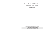
Appearance
DC Inverter Multi
VRF Service Manual
GMV-Pdm***W/NaB-M
Appearance
Model
224
280
335
400
450
504
560
GMV-Pdm***W2/NaB-M
615
670
730
785
850
900
950
GMV-Pdm***W3/NaB-M
1008
1065
1130
1180
1235
1300
1350
3
QSPEVDU
DC Inverter Multi
VRF Service Manual
GMV-Pdm***W/NaB-M
Appearance
Model
224
280
335
400
450
1405
GMV-Pdm***W4/NaB-M
1456
1512
1570
1650
1700
1750
1800
NOTES:
a.“
”represents one module and“
…
(1…N)”represents N modules.
b.“*”indicates the rated cooling capacity.
c.Design of this unit accords with the Standard GB/T 18837-2002.
d.Noise was tested in semi-silenced room, so the actual noise value will be a little higher for change of
environment..
e.The charge amount of R410A in the list is only the sealed amount when outdoor unit is outgoing. When
installing, calculate
f. the additional charge amount according to actual length of pipe and the matched indoor units;
g.Nominal capacities are based on the following conditions.
CAUTIONS
,WLVQRWUHFRPPHQGHGWRDGRSWWKHFRPELQDWLRQPRGHQRWVSHFL¿HGE\WKLVPDQXDO
QSPEVDU
4
DC Inverter Multi
VRF Service Manual
2 NOMENCLATURE
2.1 Nomenclature of Outdoor Unit
-
GMV
1
2
224 W
3
4
5
/ Na B 6
7
8
NO.
Description
1
Code for type
2
Code for model
3
Units Series
4
Nominal cooling capacity
5
Outdoor unit
9
Options
GMV: Gree Multi Variable
L: Cooling Only, Default: Heat pump
Pdm: Modular D.C. Inverter Multi-variable
224: 22.4 kW......450:45.0kW
W: Outdoor unit
Default:One module
2:Two modules
3:Three modules
4:Four modules
6
Model quantity of the Pdm series unit
7
Refrigerant
8
Series number
B: Product serial number
9
Power supply
M:3808-415V 3Ph~ 50Hz
Na: R410A
3 FUNCTION
For Comfortable Air Conditioning
Auto Restart
Fan Operation Mode
LCD Remote Controller (Option)
Auto Swing Function
Ceiling Soiling Prevention
Program Dry
High Fan Speed Mode
High Ceiling Application
Two Select Thermal Sensor
Hot Start
Timer Selector
For Easy Construction and Maintenance
Fresh Air Intake Directly from The Unit
Drain Pump
Long Life Filter
Ultra-Long life Filter (Option)
Mold Resistant Treatment for Filter
Filter Sign
Mold Resistant Drain Pan
Emergency Operation
Self Diagnoses Function
For Flexible Control
Set Back Time Clock
Double Remote Control
Group Control By 1 Remote Controller
Control By External Command
Remote/Centralized Control
5
QSPEVDU
DC Inverter Multi
VRF Service Manual
4 PRODUCT DATA
4.1 Product Data of Outdoor Unit
Model(Combined unit)
—
—
—
Model
GMV-Pdm224W/NaB-M
GMV-Pdm280W/NaB-M
GMV-Pdm335W/NaB-M
kW
22.4
28
33.5
kBtu/h
76.43
95.536
114.302
kW
25
31.5
37.5
kBtu/h
85.3
107.478
127.95
Sound Pressure Level
dB(A)
58
58
60
Power Supply
V/Hz/Ph
Cooling
Capacity
Heating
Power input
Current
380-415V~50Hz-3Ph
Cooling
kW
5.52
Heating
kW
5.82
7.7
9.38
Cooling
A
9.87
13.44
16.50
Heating
7.52
9.23
A
10.4
13.76
16.77
Circuit breaker
A
32
32
40
Recommended
Power Lines
mm2×N
6×5
6×5
10×5
Moisture protection
IP24
IP24
IP24
Climate Type
T1
T1
T1
ĭ
ĭ
ĭ
Gas Pipe
Connecting
pipe
Liquid
Pipe
Oil Pipe
mm
Inch
7/8
7/8
9/8
mm
ĭ
ĭ
ĭ
Inch
3/8
3/8
1/2
mm
—
—
—
Inch
—
—
—
Connection Method
Dimensions
of Unit
Dimensions
of Package
Brazing Connection
Brazing Connection
Brazing Connection
Width
mm
930
930
1340
Depth
mm
770
770
770
Height
mm
1670
1670
1670
Width
mm
1010
1010
1420
Depth
mm
850
850
850
Height
mm
1850
1850
1850
Net Weight
kg
255
255
350
Gross Weight
kg
275
275
380
Loading Quantity
( 20’ Container )
unit
12
12
7
Loading Quantity
( 40’ Container )
unit
24
24
16
Loading Quantity ( 40’
High Cube Container )
unit
24
24
16
Notes:
ķ The
sound level is tested under circumstance of semi-anechoic chamber; the value of noise could be a little
higher in actual operation.
ĸ The data will change with the change of products. Refer to those parameters listed on nameplate.
Ĺ The charge amount of refrigerant in the list is the datum when there is not drop height vertically between
indoor unit and outdoor unit, without consideration of connection pipe. So calculate the additional charge amount
according to actual condition during installation.
ĺ Section area of lead wire is only applicable for 15-m distance.If above, increase the section area to avoid
overload of current which would cause burnout of lead wire.
Ļ The outdoor fan of this unit is without static pressure.If static pressure is required, please specially notice it on
purchase order.
ļ R unning condition of cooling: outdoor temperature -5 ~48 ; Running condition of heating: outdoor
temperature -20 ~27 .
QSPEVDU
6
DC Inverter Multi
VRF Service Manual
Model(Combined unit)
—
—
GMV-Pdm504W2/NaB-M
Model
GMV-Pdm400W/NaB-M
GMV-Pdm450W/NaB-M
GMV-Pdm224W/NaB-M
+GMV-Pdm280W/NaB-M
Cooling
Capacity
kW
40
45
50.4
kBtu/h
136.48
153.54
171.964
kW
45
50
56.5
kBtu/h
153.54
170.6
192.778
Sound Pressure Level
dB(A)
61
61
62
Power Supply
V/Hz/Ph
Heating
Power input
Current
Cooling
kW
kW
11.2
13.9
5.82+7.70
A
22.25
25.6
9.87+13.44
Heating
A
20.02
24.85
10.4+13.76
40
40
32+32
10×5
10×5
6×5+6×5
IP24
IP24
IP24
T1
T1
T1
ĭ
Gas Pipe
Liquid
Pipe
Oil Pipe
mm
ĭ
ĭ
Inch
9/8
9/8
9/8
mm
ĭ
ĭ
ĭ
Inch
1/2
1/2
5/8
mm
—
—
ĭ
Inch
Connection Method
Dimensions
of Package
5.52+7.52
Heating
Climate Type
Dimensions
of Unit
14.32
Cooling
Circuit breaker
A
Recommended
mm2×N
Power Lines
Moisture protection
Connecting
pipe
380-415V~50Hz-3Ph
12.45
—
—
1/2
Brazing Connection
Brazing Connection
Brazing Connection
Width
mm
1340
1340
930+930
Depth
mm
770
770
770+770
Height
mm
1670
1670
1670+1670
Width
mm
1420
1420
1010+1010
Depth
mm
850
850
850+850
Height
mm
1850
1850
1850+1850
Net Weight
kg
350
370
255+255
Gross Weight
kg
380
400
275+275
Loading Quantity
( 20’ Container )
unit
7
7
——
Loading Quantity
( 40’ Container )
unit
16
16
——
Loading Quantity ( 40’
High Cube Container )
unit
24
24
——
Notes:
ķ The
sound level is tested under circumstance of semi-anechoic chamber; the value of noise could be a little
higher in actual operation.
ĸ The data will change with the change of products. Refer to those parameters listed on nameplate.
Ĺ The charge amount of refrigerant in the list is the datum when there is not drop height vertically between
indoor unit and outdoor unit, without consideration of connection pipe. So calculate the additional charge amount
according to actual condition during installation.
ĺ Section area of lead wire is only applicable for 15-m distance.If above, increase the section area to avoid
overload of current which would cause burnout of lead wire.
Ļ The outdoor fan of this unit is without static pressure.If static pressure is required, please specially notice it on
purchase order.
ļ R unning condition of cooling: outdoor temperature -5 ~48 ; Running condition of heating: outdoor
temperature -20 ~27 .
7
QSPEVDU
DC Inverter Multi
VRF Service Manual
Model(Combined unit)
GMV-Pdm560W2/NaB-M
GMV-Pdm615W2/NaB-M
GMV-Pdm670W2/NaB-M
Model
GMV-Pdm280W/NaB-M
+GMV-Pdm280W/NaB-M
GMV-Pdm280W/NaB-M
+GMV-Pdm335W/NaB-M
GMV-Pdm280W/NaB-M
+GMV-Pdm400W/NaB-M
Cooling
Capacity
kW
56.0
61.5
68.0
kBtu/h
191.072
209.838
232.016
kW
63.0
69.0
76.5
kBtu/h
214.956
235.428
261.018
Sound Pressure Level
dB(A)
62
62
62
Power Supply
V/Hz/Ph
Heating
Power input
Cooling
kW
380-415V~50Hz-3Ph
7.52+7.52
7.52+9.23
7.52+12.45
Heating
kW
7.70+7.70
7.70+9.38
7.70+11.2
Cooling
A
13.44+13.44
13.44+16.50
13.44+22.25
Heating
A
13.76+13.76
13.76+16.77
13.76+20.02
Circuit breaker
A
32+32
32+40
32+40
Recommended
Power Lines
mm2×N
6×5+6×5
6×5+10×5
6×5+10×5
Moisture protection
IP24
IP24
IP24
Climate Type
T1
T1
T1
ĭ
Current
Gas Pipe
Connecting
pipe
Liquid
Pipe
Oil Pipe
mm
ĭ
ĭ
Inch
9/8
9/8
9/8
mm
ĭ
ĭ
ĭ
Inch
5/8
5/8
5/8
mm
ĭ
ĭ
ĭ
Inch
Connection Method
Width
Dimensions
of Unit
Dimensions
of Package
mm
1/2
1/2
1/2
Brazing Connection
Brazing Connection
Brazing Connection
930+930
930+1340
930+1340
Depth
mm
770+770
770+770
770+770
Height
mm
1670+1670
1670+1670
1670+1670
Width
mm
1010+1010
1010+1420
1010+1420
Depth
mm
850+850
850+850
850+850
Height
mm
1850+1850
1850+1850
1850+1850
Net Weight
kg
255+255
255+350
255+350
Gross Weight
kg
275+275
275+380
275+380
Loading Quantity
( 20’ Container )
unit
——
——
——
Loading Quantity
( 40’ Container )
unit
——
——
——
Loading Quantity ( 40’
High Cube Container )
unit
——
——
——
Notes:
ķ The
sound level is tested under circumstance of semi-anechoic chamber; the value of noise could be a little
higher in actual operation.
ĸ The data will change with the change of products. Refer to those parameters listed on nameplate.
Ĺ The charge amount of refrigerant in the list is the datum when there is not drop height vertically between
indoor unit and outdoor unit, without consideration of connection pipe. So calculate the additional charge amount
according to actual condition during installation.
ĺ Section area of lead wire is only applicable for 15-m distance.If above, increase the section area to avoid
overload of current which would cause burnout of lead wire.
Ļ The outdoor fan of this unit is without static pressure.If static pressure is required, please specially notice it on
purchase order.
ļ R unning condition of cooling: outdoor temperature -5 ~48 ; Running condition of heating: outdoor
temperature -20 ~27 .
QSPEVDU
8
DC Inverter Multi
VRF Service Manual
Model(Combined unit)
GMV-Pdm730W2/NaB-M
GMV-Pdm785W2/NaB-M
GMV-Pdm850W2/NaB-M
Model
GMV-Pdm280W/NaB-M
+GMV-Pdm450W/NaB-M
GMV-Pdm335W/NaB-M
+GMV-Pdm450W/NaB-M
GMV-Pdm400W/NaB-M
+GMV-Pdm450W/NaB-M
Cooling
Capacity
kW
73.0
80.0
85.0
kBtu/h
249.076
272.960
290.020
kW
81.5
90.0
95.0
kBtu/h
278.078
307.080
324.140
Sound Pressure Level
dB(A)
63
63
63
Power Supply
V/Hz/Ph
Heating
Power input
380-415V~50Hz-3Ph
Cooling
kW
7.52+14.32
9.23+14.32
12.45+14.32
Heating
kW
7.70+13.90
9.38+13.90
11.20+13.90
Cooling
A
13.44+25.6
16.50+25.60
22.25+25.60
Heating
A
13.76+24.85
16.77+24.85
20.02+24.85
A
32+40
40+40
40+40
2
6×5+10×5
10×5+10×5
10×5+10×5
Moisture protection
IP24
IP24
IP24
Climate Type
T1
T1
T1
ĭ
Current
Circuit breaker
Recommended
Power Lines
Gas Pipe
Connecting
pipe
Liquid
Pipe
Oil Pipe
mm ×N
mm
ĭ
ĭ
Inch
11/8
11/8
11/8
mm
ĭ
ĭ
ĭ
Inch
3/4
3/4
3/4
mm
ĭ
ĭ
ĭ
Inch
Connection Method
Width
Dimensions
of Unit
Dimensions
of Package
mm
1/2
1/2
1/2
Brazing Connection
Brazing Connection
Brazing Connection
930+1340
1340+1340
1340+1340
Depth
mm
770+770
770+770
770+770
Height
mm
1670+1670
1670+1670
1670+1670
Width
mm
1010+1420
1420+1420
1420+1420
Depth
mm
850+850
850+850
850+850
Height
mm
1850+1850
1850+1850
1850+1850
Net Weight
kg
255+370
350+370
350+370
Gross Weight
kg
275+400
380+400
380+400
Loading Quantity
( 20’ Container )
unit
——
——
——
Loading Quantity
( 40’ Container )
unit
——
——
——
Loading Quantity ( 40’
High Cube Container )
unit
——
——
——
Notes:
ķ The
sound level is tested under circumstance of semi-anechoic chamber; the value of noise could be a little
higher in actual operation.
ĸ The data will change with the change of products. Refer to those parameters listed on nameplate.
Ĺ The charge amount of refrigerant in the list is the datum when there is not drop height vertically between
indoor unit and outdoor unit, without consideration of connection pipe. So calculate the additional charge amount
according to actual condition during installation.
ĺ Section area of lead wire is only applicable for 15-m distance.If above, increase the section area to avoid
overload of current which would cause burnout of lead wire.
Ļ The outdoor fan of this unit is without static pressure.If static pressure is required, please specially notice it on
purchase order.
ļ R unning condition of cooling: outdoor temperature -5 ~48 ; Running condition of heating: outdoor
temperature -20 ~27 .
9
QSPEVDU
DC Inverter Multi
VRF Service Manual
Model(Combined unit)
Model
Cooling
Capacity
GMV-Pdm900W2/NaB-M
GMV-Pdm950W3/NaB-M
GMV-Pdm1008W3/NaB-M
GMV-Pdm450W/NaB-M
+GMV-Pdm450W/NaB-M
GMV-Pdm280W/NaB-M
+GMV-Pdm280W/NaB-M
+GMV-Pdm400W/NaB-M
GMV-Pdm280W/NaB-M
+GMV-Pdm280W/NaB-M
+GMV-Pdm450W/NaB-M
kW
90.0
96.0
101.0
kBtu/h
307.080
327.552
344.612
kW
100.0
108.0
113.0
kBtu/h
341.200
368.496
385.526
Sound Pressure Level
dB(A)
63
64
64
Power Supply
V/Hz/Ph
Heating
Power input
380-415V~50Hz-3Ph
Cooling
kW
14.32+14.32
7.52+7.52+12.45
7.52+7.52+14.32
Heating
kW
13.90+13.90
7.70+7.70+11.2
7.70+7.70+13.90
Cooling
A
25.6+25.6
13.44+13.44+22.25
13.44+13.44+25.6
Heating
A
24.85+24.85
13.76+13.76+20.02
13.76+13.76+24.85
Circuit breaker
A
40+40
32+32+40
32+32+40
Recommended
Power Lines
mm2×N
10×5+10×5
6×5+6×5+10×5
6×5+6×5+10×5
IP24
IP24
IP24
Current
Moisture protection
Climate Type
Gas Pipe
Connecting
pipe
Liquid
Pipe
Oil Pipe
T1
T1
T1
mm
ĭ
ĭ
ĭ
Inch
11/8
11/8
13/8
ĭ
mm
ĭ
ĭ
Inch
3/4
3/4
3/4
mm
ĭ
ĭ
ĭ
Inch
Connection Method
Width
Dimensions
of Unit
Dimensions
of Package
mm
1/2
1/2
1/2
Brazing Connection
Brazing Connection
Brazing Connection
1340+1340
930+930+1340
930+930+1340
Depth
mm
770+770
770+770+770
770+770+770
Height
mm
1670+1670
1670+1670+1670
1670+1670+1670
Width
mm
1420+1420
1010+1010+1420
1010+1010+1420
Depth
mm
850+850
850+850+850
850+850+850
Height
mm
1850+1850
1850+1850+1850
1850+1850+1850
Net Weight
kg
370+370
255+255+350
255+255+370
Gross Weight
kg
400+400
275+275+380
275+275+400
Loading Quantity
( 20’ Container )
unit
——
——
——
Loading Quantity
( 40’ Container )
unit
——
——
——
Loading Quantity ( 40’
High Cube Container )
unit
——
——
——
Notes:
ķ The
sound level is tested under circumstance of semi-anechoic chamber; the value of noise could be a little
higher in actual operation.
ĸ The data will change with the change of products. Refer to those parameters listed on nameplate.
Ĺ The charge amount of refrigerant in the list is the datum when there is not drop height vertically between
indoor unit and outdoor unit, without consideration of connection pipe. So calculate the additional charge amount
according to actual condition during installation.
ĺ Section area of lead wire is only applicable for 15-m distance.If above, increase the section area to avoid
overload of current which would cause burnout of lead wire.
Ļ The outdoor fan of this unit is without static pressure.If static pressure is required, please specially notice it on
purchase order.
ļ R unning condition of cooling: outdoor temperature -5 ~48 ; Running condition of heating: outdoor
temperature -20 ~27 .
QSPEVDU
10
DC Inverter Multi
VRF Service Manual
Model(Combined unit)
GMV-Pdm1065W3/NaB-M
GMV-Pdm1130W3/NaB-M
GMV-Pdm1180W3/NaB-M
Model
GMV-Pdm280W/NaB-M
+GMV-Pdm335W/NaB-M
+GMV-Pdm450W/NaB-M
GMV-Pdm280W/NaB-M
+GMV-Pdm400W/NaB-M
+GMV-Pdm450W/NaB-M
GMV-Pdm280W/NaB-M
+GMV-Pdm450W/NaB-M
+GMV-Pdm450W/NaB-M
Cooling
Capacity
kW
108.0
113.0
118.0
kBtu/h
368.469
385.556
402.616
kW
121.5
126.5
131.5
kBtu/h
414.558
431.618
448.678
Sound Pressure Level
dB(A)
64
64
64
Power Supply
V/Hz/Ph
Heating
380-415V~50Hz-3Ph
Cooling
kW
7.52+9.23+14.32
7.52+12.45+14.32
7.52+14.32+14.32
Heating
kW
7.70+9.38+13.9
7.70+11.2+13.9
7.70+13.90+13.90
Cooling
A
13.44+16.50+25.6
13.44+22.25+25.6
13.44+25.6+25.6
Heating
A
13.76+16.77+24.85
13.76+20.02+24.85
13.76+24.85+24.85
Circuit breaker
A
32+40+40
32+40+40
32+40+40
Recommended
Power Lines
mm2×N
6×5+10×5+10×5
6×5+10×5+10×5
6×5+10×5+10×5
IP24
IP24
IP24
Power input
Current
Moisture protection
Climate Type
Gas Pipe
Connecting
pipe
Liquid
Pipe
Oil Pipe
mm
Dimensions
of Package
T1
T1
ĭ
ĭ
Inch
13/8
13/8
13/8
mm
ĭ
ĭ
ĭ
Inch
3/4
3/4
3/4
mm
ĭ
ĭ
ĭ
Inch
1/2
1/2
1/2
Connection Method
Dimensions
of Unit
T1
ĭ
Brazing Connection
Brazing Connection
Brazing Connection
Width
mm
930+1340+1340
930+1340+1340
930+1340+1340
Depth
mm
770+770+770
770+770+770
770+770+770
Height
mm
1670+1670+1670
1670+1670+1670
1670+1670+1670
Width
mm
1010+1420+1420
1010+1420+1420
1010+1420+1420
Depth
mm
850+850+850
850+850+850
850+850+850
Height
mm
1850+1850+1850
1850+1850+1850
1850+1850+1850
Net Weight
kg
255+350+370
255+350+370
255+370+370
Gross Weight
kg
275+380+400
275+380+400
275+400+400
Loading Quantity
( 20’ Container )
unit
——
——
——
Loading Quantity
( 40’ Container )
unit
——
——
——
Loading Quantity ( 40’
High Cube Container )
unit
——
——
——
Notes:
ķ The
sound level is tested under circumstance of semi-anechoic chamber; the value of noise could be a little
higher in actual operation.
ĸ The data will change with the change of products. Refer to those parameters listed on nameplate.
Ĺ The charge amount of refrigerant in the list is the datum when there is not drop height vertically between
indoor unit and outdoor unit, without consideration of connection pipe. So calculate the additional charge amount
according to actual condition during installation.
ĺ Section area of lead wire is only applicable for 15-m distance.If above, increase the section area to avoid
overload of current which would cause burnout of lead wire.
Ļ The outdoor fan of this unit is without static pressure.If static pressure is required, please specially notice it on
purchase order.
ļ R unning condition of cooling: outdoor temperature -5 ~48 ; Running condition of heating: outdoor
temperature -20 ~27 .
11
QSPEVDU
DC Inverter Multi
VRF Service Manual
Model(Combined unit)
GMV-Pdm1235W3/NaB-M
GMV-Pdm1300W3/NaB-M
GMV-Pdm1350W3/NaB-M
Model
GMV-Pdm335W/NaB-M
+GMV-Pdm450W/NaB-M
+GMV-Pdm450W/NaB-M
GMV-Pdm400W/NaB-M
+GMV-Pdm450W/NaB-M
+GMV-Pdm450W/NaB-M
GMV-Pdm450W/NaB-M
+GMV-Pdm450W/NaB-M
+GMV-Pdm450W/NaB-M
Cooling
Capacity
kW
125.0
130.0
135.0
kBtu/h
426.500
443.560
460.620
kW
14.0
145.0
150.0
kBtu/h
477.680
494.740
511.800
Sound Pressure Level
dB(A)
65
65
65
Power Supply
V/Hz/Ph
Heating
Power input
380-415V~50Hz-3Ph
Cooling
kW
9.23+14.32+14.32
12.45+14.32+14.32
14.32+14.32+14.32
Heating
kW
9.38+13.9+13.9
11.2+13.9+13.9
13.90+13.90+13.90
Cooling
A
16.5+25.6+25.6
22.25+25.6+25.6
25.6+25.6+25.6
Heating
A
16.77+24.85+24.85
20.02+24.85+24.85
24.85+24.85+24.85
Circuit breaker
A
40+40+40
40+40+40
40+40+40
Recommended
Power Lines
mm2×N
10×5+10×5+10×5
10×5+10×5+10×5
10×5+10×5+10×5
IP24
IP24
IP24
Current
Moisture protection
Climate Type
Gas Pipe
Connecting
pipe
Liquid
Pipe
Oil Pipe
mm
Dimensions
of Package
T1
T1
ĭ
ĭ
Inch
13/8
13/8
13/8
mm
ĭ
ĭ
ĭ
Inch
3/4
3/4
3/4
mm
ĭ
ĭ
ĭ
Inch
1/2
1/2
1/2
Connection Method
Dimensions
of Unit
T1
ĭ
Brazing Connection
Brazing Connection
Brazing Connection
Width
mm
1340+1340+1340
1340+1340+1340
1340+1340+1340
Depth
mm
770+770+770
770+770+770
770+770+770
Height
mm
1670+1670+1670
1670+1670+1670
1670+1670+1670
Width
mm
1420+1420+1420
1420+1420+1420
1420+1420+1420
Depth
mm
850+850+850
850+850+850
850+850+850
Height
mm
1850+1850+1850
1850+1850+1850
1850+1850+1850
Net Weight
kg
350+370+370
350+370+370
370+370+370
Gross Weight
kg
380+400+400
380+400+400
400+400+400
Loading Quantity
( 20’ Container )
unit
——
——
——
Loading Quantity
( 40’ Container )
unit
——
——
——
Loading Quantity ( 40’
High Cube Container )
unit
——
——
——
Notes:
ķ The
sound level is tested under circumstance of semi-anechoic chamber; the value of noise could be a little
higher in actual operation.
ĸ The data will change with the change of products. Refer to those parameters listed on nameplate.
Ĺ The charge amount of refrigerant in the list is the datum when there is not drop height vertically between
indoor unit and outdoor unit, without consideration of connection pipe. So calculate the additional charge amount
according to actual condition during installation.
ĺ Section area of lead wire is only applicable for 15-m distance.If above, increase the section area to avoid
overload of current which would cause burnout of lead wire.
Ļ The outdoor fan of this unit is without static pressure.If static pressure is required, please specially notice it on
purchase order.
ļ R unning condition of cooling: outdoor temperature -5 ~48 ; Running condition of heating: outdoor
temperature -20 ~27 .
QSPEVDU
12
DC Inverter Multi
VRF Service Manual
Model(Combined unit)
GMV-Pdm1405W4/NaB-M
GMV-Pdm1456W4/NaB-M
GMV-Pdm1512W4/NaB-M
Model
GMV-Pdm280W/NaB-M
+GMV-Pdm280W/NaB-M
+GMV-Pdm400W/NaB-M
+GMV-Pdm450W/NaB-M
GMV-Pdm280W/NaB-M
+GMV-Pdm280W/NaB-M
+GMV-Pdm450W/NaB-M
+GMV-Pdm450W/NaB-M
GMV-Pdm280W/NaB-M
+GMV-Pdm335W/NaB-M
+GMV-Pdm450W/NaB-M
+GMV-Pdm450W/NaB-M
Cooling
Capacity
kW
141.0
146.0
153.0
kBtu/h
481.092
498.152
522.036
kW
158.0
163.0
171.0
kBtu/h
539.096
556.156
585.158
Sound Pressure Level
dB(A)
65
65
65
Power Supply
V/Hz/Ph
Heating
Power input
Current
kW
7.52+7.52+12.45+14.32
7.52+7.52+14.32+14.32
7.52+9.23+14.32+14.32
Heating
kW
7.707.70+11.2+13.9
7.70+7.70+13.90+13.90
7.70+9.38+13.90+13.90
Cooling
A
13.44+13.44+22.25+25.6
13.44+13.44+25.6+25.6
13.44+16.50+25.6+25.6
Heating
A
13.76+13.76+20.02+24.85
13.76+13.76+24.85+24.85
13.76+16.77+24.85+24.85
31+32+40+40
32+32+40+40
32+40+40+40
6×5+6×5+10×5+10×5
6×5+6×5+10×5+10×5
6×5+10×5+10×5+10×5
IP24
IP24
IP24
Circuit breaker
A
Recommended
mm2×N
Power Lines
Moisture protection
Climate Type
Connecting
pipe
T1
T1
T1
Gas
Pipe
mm
ĭ
ĭ
ĭ
Inch
7/4
7/4
13/8
Liquid
Pipe
mm
ĭ
ĭ
ĭ
Inch
7/8
7/8
3/4
mm
ĭ
ĭ
ĭ
Oil Pipe
Inch
Connection Method
Width
Dimensions
of Unit
Dimensions
of Package
380-415V~50Hz-3Ph
Cooling
mm
1/2
1/2
1/2
Brazing Connection
Brazing Connection
Brazing Connection
930+930+1340+1340
930+930+1340+1340
930+1340+1340+1340
Depth
mm
770+770+770+770
770+770+770+770
770+770+770+770
Height
mm
1670+1670+1670+1670
1670+1670+1670+1670
1670+1670+1670+1670
Width
mm
1010+1010+1420+1420
1010+1010+1420+1420
1010+1420+1420+1420
Depth
mm
850+850+850+850
850+850+850+850
850+850+850+850
Height
mm
1850+1850+1850+1850
1850+1850+1850+1850
1850+1850+1850+1850
Net Weight
kg
255+255+350+370
255+255+370+370
255+350+370+370
Gross Weight
kg
275+275+380+400
275+275+400+400
275+380+400+400
Loading Quantity
( 20’ Container )
unit
——
——
——
Loading Quantity
( 40’ Container )
unit
——
——
——
Loading Quantity ( 40’
High Cube Container )
unit
——
——
——
Notes:
ķ The
sound level is tested under circumstance of semi-anechoic chamber; the value of noise could be a little
higher in actual operation.
ĸ The data will change with the change of products. Refer to those parameters listed on nameplate.
Ĺ The charge amount of refrigerant in the list is the datum when there is not drop height vertically between
indoor unit and outdoor unit, without consideration of connection pipe. So calculate the additional charge amount
according to actual condition during installation.
ĺ Section area of lead wire is only applicable for 15-m distance.If above, increase the section area to avoid
overload of current which would cause burnout of lead wire.
Ļ The outdoor fan of this unit is without static pressure.If static pressure is required, please specially notice it on
purchase order.
ļ R unning condition of cooling: outdoor temperature -5 ~48 ; Running condition of heating: outdoor
temperature -20 ~27 .
13
QSPEVDU
DC Inverter Multi
VRF Service Manual
Model(Combined unit)
kW
GMV-Pdm1570W4/NaB-M
GMV-Pdm280W/NaB-M
+GMV-Pdm400W/NaB-M
+GMV-Pdm450W/NaB-M
+GMV-Pdm450W/NaB-M
155.0
GMV-Pdm1650W4/NaB-M
GMV-Pdm280W/NaB-M
+GMV-Pdm450W/NaB-M
+GMV-Pdm450W/NaB-M
+GMV-Pdm450W/NaB-M
163.0
GMV-Pdm1700W4/NaB-M
GMV-Pdm335W/NaB-M
+GMV-Pdm450W/NaB-M
+GMV-Pdm450W/NaB-M
+GMV-Pdm450W/NaB-M
170.0
kBtu/h
528.860
556.156
580.040
Model
Cooling
Capacity
kW
176.5
181.5
190.0
kBtu/h
602.218
619.278
648.280
Sound Pressure Level
dB(A)
65
65
66
Power Supply
V/Hz/Ph
Heating
Power input
Current
kW
7.52+12.45+14.32+14.32
7.52+14.32+14.32+14.32
9.23+14.32+14.32+14.32
Heating
kW
7.70+11.2+13.9+13.9
7.70+13.9013.90+13.90
9.38+13.9+13.9+13.9
Cooling
A
13.44+22.25+25.6+25.6
13.44+25.6+25.6+25.6
16.5+25.6+25.6+25.6
Heating
A
13.76+20.02+24.85+24.85
13.76+24.85+24.85+24.85
16.77+24.58+24.85+24.85
32+40+40+40
32+40+40+40
40+40+40+40
6×5+10×5+10×5+10×5
6×5+10×5+10×5+10×5
10×5+10×5+10×5+10×5
IP24
IP24
IP24
Circuit breaker
A
Recommended
mm2×N
Power Lines
Moisture protection
Climate Type
Connecting
pipe
T1
T1
T1
Gas
Pipe
mm
ĭ
ĭ
ĭ
Inch
7/4
17/8
17/8
Liquid
Pipe
mm
ĭ
ĭ
ĭ
Inch
7/8
1
1
mm
ĭ
ĭ
ĭ
Oil Pipe
Inch
Connection Method
Width
Dimensions
of Unit
Dimensions
of Package
380-415V~50Hz-3Ph
Cooling
mm
1/2
1/2
1/2
Brazing Connection
Brazing Connection
Brazing Connection
930+1340+1340+1340
930+1340+1340+1340
1340+1340+1340+1340
Depth
mm
770+770+770+770
770+770+770+770
770+770+770+770
Height
mm
1670+1670+1670+1670
1670+1670+1670+1670
1670+1670+1670+1670
Width
mm
1010+1420+1420+1420
1010+1420+1420+1420
1420+1420+1420+1420
Depth
mm
850+850+850+850
850+850+850+850
850+850+850+850
Height
mm
1850+1850+1850+1850
1850+1850+1850+1850
1850+1850+1850+1850
Net Weight
kg
255+350+370+370
255+370+370+370
350+370+370+370
Gross Weight
kg
275+380+400+400
275+400+400+400
380+400+400+400
Loading Quantity
( 20’ Container )
unit
——
——
——
Loading Quantity
( 40’ Container )
unit
——
——
——
Loading Quantity ( 40’
High Cube Container )
unit
——
——
——
Notes:
ķ The
sound level is tested under circumstance of semi-anechoic chamber; the value of noise could be a little
higher in actual operation.
ĸ The data will change with the change of products. Refer to those parameters listed on nameplate.
Ĺ The charge amount of refrigerant in the list is the datum when there is not drop height vertically between
indoor unit and outdoor unit, without consideration of connection pipe. So calculate the additional charge amount
according to actual condition during installation.
ĺ Section area of lead wire is only applicable for 15-m distance.If above, increase the section area to avoid
overload of current which would cause burnout of lead wire.
Ļ The outdoor fan of this unit is without static pressure.If static pressure is required, please specially notice it on
purchase order.
ļ R unning condition of cooling: outdoor temperature -5 ~48 ; Running condition of heating: outdoor
temperature -20 ~27 .
QSPEVDU
14
DC Inverter Multi
VRF Service Manual
Model(Combined unit)
kW
GMV-Pdm1750W4/NaB-M
GMV-Pdm400W/NaB-M
+GMV-Pdm450W/NaB-M
+GMV-Pdm450W/NaB-M
+GMV-Pdm450W/NaB-M
175.0
GMV-Pdm1800W4/NaB-M
GMV-Pdm450W/NaB-M
+GMV-Pdm450W/NaB-M
+GMV-Pdm450W/NaB-M
+GMV-Pdm450W/NaB-M
180.0
kBtu/h
597.100
614.160
Model
Cooling
Capacity
kW
195.0
200.0
kBtu/h
665.340
682.400
Sound Pressure Level
dB(A)
66
66
Power Supply
V/Hz/Ph
Heating
Power input
Current
Cooling
kW
12.45+14.32+14.32+14.32
14.32+14.32+14.32+14.32
Heating
kW
11.2+13.9013.90+13.90
13.9+13.9+13.9+13.9
Cooling
A
22.25+25.6+25.6+25.6
25.6+25.6+25.6+25.6
Heating
A
20.02+24.85+24.85+24.85
24.85+24.85+24.85+24.85
40+40+40+40
40+40+40+40
10×5+10×5+10×5+10×5
10×5+10×5+10×5+10×5
IP24
IP24
Circuit breaker
A
Recommended
mm2×N
Power Lines
Moisture protection
Climate Type
Connecting
pipe
T1
T1
Gas
Pipe
mm
ĭ
ĭ
Inch
17/8
17/8
Liquid
Pipe
mm
ĭ
ĭ
Inch
1
1
mm
ĭ
ĭ
Oil Pipe
Inch
Connection Method
Width
Dimensions
of Unit
Dimensions
of Package
mm
1/2
1/2
Brazing Connection
Brazing Connection
1340+1340+1340+1340
1340+1340+1340+1340
Depth
mm
770+770+770+770
770+770+770+770
Height
mm
1670+1670+1670+1670
1670+1670+1670+1670
Width
mm
1420+1420+1420+1420
1420+1420+1420+1420
Depth
mm
850+850+850+850
850+850+850+850
Height
mm
1850+1850+1850+1850
1850+1850+1850+1850
Net Weight
kg
350+370+370+370
370+370+370+370
Gross Weight
kg
380+400+400+400
400+400+400+400
Loading Quantity
( 20’ Container )
unit
——
——
Loading Quantity
( 40’ Container )
unit
——
——
Loading Quantity ( 40’
High Cube Container )
unit
——
——
Notes:
ķ The
sound level is tested under circumstance of semi-anechoic chamber; the value of noise could be a little
higher in actual operation.
ĸ The data will change with the change of products. Refer to those parameters listed on nameplate.
Ĺ The charge amount of refrigerant in the list is the datum when there is not drop height vertically between
indoor unit and outdoor unit, without consideration of connection pipe. So calculate the additional charge amount
according to actual condition during installation.
ĺ Section area of lead wire is only applicable for 15-m distance.If above, increase the section area to avoid
overload of current which would cause burnout of lead wire.
Ļ The outdoor fan of this unit is without static pressure.If static pressure is required, please specially notice it on
purchase order.
ļ R unning condition of cooling: outdoor temperature -5 ~48 ; Running condition of heating: outdoor
temperature -20 ~27 .
15
QSPEVDU
DC Inverter Multi
VRF Service Manual
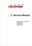
5 PIPING DIAGRAM
5.1 Piping diagram of GMV-Pdm224W/NaB-M,GMV-Pdm280W/NaB-M
˄˅
˄˅
˄˅
˄˅
˄˅
˄˅
˄˅
˄˅
˄˅
˄˅
˄˅
˄˅
˄˅
˄˅
˄˅
˄˅
˄˅
˄˅
˄˅
˄˅
˄˅
˄˅
˄˅
QSPEVDU
16
˄˅
˄˅
˄˅
˄˅
˄˅
˄˅
DC Inverter Multi
VRF Service Manual
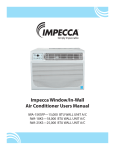
5.2 Piping diagram of GMV-Pdm335W/NaB-M,GMV-Pdm400W/NaB-M,GMV-Pdm450W/NaB-M
˄˅
˄˅
˄˅
˄˅
˄˅
˄˅
˄˅
˄˅
˄˅
˄˅
˄˅
˄˅
˄˅
˄˅
˄˅
˄˅
˄˅
˄˅
˄˅
˄˅
˄˅
˄˅
˄˅
˄˅
˄˅
˄˅
˄˅
˄˅
˄˅
˄˅
˄˅
˄˅
NO.
Name
Major Function
According to the actual need, the inverter compressor
can adjust its revolution among 30rps~90rps.
1
Inverter compressor(INV)
2
Standard compressor(STD1/STD2)
3
High pressure switch(for INV)
When the discharge pressure of the inverter compressor
exceeds the upper limit of the high pressure switch,
a feedback signal will be sent out to stop the unit
immediately so as to protect the compressor.
4
High pressure switch(for STD1/ STD2)
:KHQWKHGLVFKDUJHSUHVVXUHRIWKH¿[HGIUHTXHQF\
compressor exceeds the upper limit of the high pressure
switch, a feedback signal will be sent out to stop the
unit immediately so as to protect the compressor.
5
Check valve(for INV)
When the inverter compressor fails to meet the needs of the
V\VWHPWKH¿[HGIUHTXHQF\FRPSUHVVRUZLOOVWDUWWRJHWKHU
It is used to prevent the high-pressure reverse gas going into the
inverter compressor at the moment that the compressor stops
so as to avoid abnormal startup next time and other problems.
17
QSPEVDU
DC Inverter Multi
VRF Service Manual
QSPEVDU
18
It is used to prevent the high-pressure reverse gas going into the
¿[HGIUHTXHQF\FRPSUHVVRUDWWKHPRPHQWWKHFRPSUHVVRUVWRSV
so as to avoid abnormal startup next time and other problems.
6
Check valve(for STD1/ STD2)
7
Oil separator
It is used to separate the gas and oil so as to
guarantee the reliability of the compressor.
8
Check valve
It is used to prevent the high-pressure reverse gas going
into the modules at the moment that the unit stops
9
Four way valve
It is used to change the status of the heat exchanger.
10
Heat exchanger
It is used to exchanger heat outdoor.
11
Check valve
12
Electronic expansion valve
13
Receiver
14
Check valve (for cooling)
It is used under the cooling mode.
15
Solenoid valve (for heating)
It is used under the cooling mode.
16
Check valve
It is used under the cooling mode.
17
Filter-drier
18
High pressure sensor
It is used to detect the real-time high pressure for
protecting the compressor and other controls.
19
Low pressure sensor
It is used to detect the real-time low pressure for
protecting the compressor and other controls.
20
Solenoid valve (hot gas)
21
Solenoid valve (liquid bypass)
22
Accumulator
23
Solenoid valve(INV)
24
Solenoid valve(STD1/ STD2)
25
Solenoid valve(Oil balance)
26
Servicing valve
It is where the low pressure can be measured and
refrigerant can be charged for after-sales maintenance.
27
Liquid pipe
It is the pipe to pass the refrigerant liquid of the system.
28
Gas pipe
29
Oil balance pipe
,WLVXVHGWRUHGXFHWKHSUHVVXUHORVVRIWKHUHIULJHUDQWÀRZ
It is used to adjust the degree of superheat and then
DGMXVWWKHUHIULJHUDQWÀRZWRHQVXUHWKHUHOLDELOLW\
DQGVXI¿FLHQWKHDWH[FKDQJHRIWKHV\VWHP
It is used to store unused refrigerant to avoid abnormity.
It is used to absorb moisture in the system so as to avoid “ice
plug” or “copper plating” on the surface of the compressor
It is used to protect the system running under low pressure
or the compressor starting with pressure difference.
It is used to prevent the compressor running at high temperature.
It is used to prevent the compressor running
at high humidity condition.
It is used to return the lubricant to the inverter compressor.
,WLVXVHGWRUHWXUQWKHOXEULFDQWWRWKH¿[HGIUHTXHQF\FRPSUHVVRU
It is used to balance the lubricant among modules.
It is the pipe to pass the refrigerant gas of the system.
It is the pipe to balance the lubricant oil between modules.
DC Inverter Multi
VRF Service Manual
CONTROL
19
DPOUSPM
DC Inverter Multi
VRF Service Manual
CONTROL
1 CONTROL OF THE UNIT
1.1 Concept of Integral Control of the Unit
1.1.1 Unit Control Schematic Diagram
Inverter drive control system
2 - core communication cable
3 - core pin header
Adap for
board
Mainboard of
indoor unit
4 - core
communication
cable
Mainboard of
indoor unit
Display board
of indoor unit
Display board
of indoor unit
Display board
of indoor unit
Indoor unit n+1
Indoor unit n
Indoor unit 1
Indoor unit, a maximum of 16 sets to be connected
Electronic
expansion
valve
Temperature sensor
Mainboard of
indoor unit
Main control board of outdoor unit
Relay output High and low
control
pressure switch
protection input
Outdoor Unit
Air conditioning units can be divided into indoor unit and outdoor unit. A maximum of 16 sets of indoor units can
be connected to an outdoor unit. 2-core (3-core pin header) communication cable is used for the connection between
indoor unit and outdoor unit. Indoor unit is connected to display board via 4-core communication cable. In engineering
installation, address dial-up of the display board and the mainboard of indoor unit shall be dialed. The address dial-up of
the mainboard of indoor unit must be identical with that of the display board of the same indoor unit. Address dial-up of
different indoor unit must vary. Multi VRF indoor unit is applicable to all digital or inverter outdoor units.
Controller of outdoor unit falls into two categories in terms of its function, i.e. main control system and inverter drive
control system
1.1.2 DC Inverter Unit
1) Main control system
A. Functions: main control system shall be connected to indoor unit through 2-core (3-core pin header)
communication cable in order to receive start or stop commands, mode, setting temperature and ambient temperature
from indoor unit, determine operation mode of outdoor unit, and through calculation based on capacity, decide proper
running frequency which shall be sent to the drive control system through 2-core (3-core pin header) communication cable.
Fan speed shall be regulated according to system pressure. Real-time monitoring of temperature sensors, operation state
and protection of unit shall be performed to ensure normal and stable operation of the whole system. Protection codes
of outdoor unit shall be displayed on the LED on the main control board when failure occurs. When drive is at fault, E5
VKDOOEHGLVSOD\HGRQWKHGLVSOD\ERDUGRILQGRRUXQLWDQGVSHFL¿FIDLOXUHW\SHVKDOOEHLQGLFDWHGRQWKH/('RQWKHPDLQ
control board of outdoor unit.
B. Input and output controlled variables
Sensors include ambient temp. sensor, tube-inlet temp. sensor, tube-middle temp. sensor, tube-outlet temp. sensor,
compressor exhaust temp. sensor, compressor casing top temp. sensor, high pressure sensor and low pressure sensor.
Switch protection: high pressure protection, over-current protection
Output control objects: fan frequency, compressor heat tape (controlled by drive board), compressor AC contactor
(3-phase, controlled by drive board), gas bypass valve, 4-way valve, solenoid valve A, oil equilibrium valve, liquid bypass
valve and capillary solenoid valve.
DPOUSPM
20
DC Inverter Multi
VRF Service Manual
C. 485 communication interface: indoor unit communication network and adaptor board CN1 shall be connected
to the mainboard of indoor unit through 2-core (3-core pin header) communication cable; drive communication network
and the mainboards CN11~CN14 of outdoor unit shall be connected to the drive board through 2-core (3-core pin header)
communication cable.
2) Drive control system
3-phase power supply unit
Reactor
M
L1,L2,
L3,N
L1,L2,
L3,N
Communication
Functions of various modules:
$ )LOWHUSODWHRQHRIWKHWZRNH\IXQFWLRQVLVWR¿OWHUDQGHOLPLQDWHSRZHULQWHUIHUHQFHVDQGHQVXUHDQWLLQWHUIHUHQFH
capability of the unit even in a rugged power supply environment; the other one is to suppress interferences from power
supply in order to prevent the operation of the unit from affecting other appliances such as TV. Because inverter unit works
LQDVSHFLDOZD\WKDWLVUHODWLYHO\VHQVLWLYHWRLQWHUIHUHQFHV¿OWHUSODWHLVQRUPDOO\DUUDQJHG%HFDXVHSKDVHSRZHUVXSSO\
LVXVHGIRUWKHXQLWSKDVH¿OWHUSODWHWKDWXVHVVWDJH¿OWHULQJPRGHVKDOOEHHPSOR\HG,QSXWWHUPLQDOVRISKDVH¿OWHU
plate are respectively AC-L1, AC-L2,AC-L3 and N, and corresponding output terminals are respectively L1-OUT,L2-OUT,
L3-OUT and N-OUT.
B Drive board is a key part of control system. Receiving commands from the main control board, the drive board
can transform 380V, 50Hz, 3-phase commercial power into AC power with adjustable amplitude and frequency, capable to
drive compressor.
21
DPOUSPM
DC Inverter Multi
VRF Service Manual
1.2 Operation Flow Chart of the Unit
Conne cting To Power Suppl y
Initialization Of Bectroni c
Expansion Valve
Volume:Air Supply Direction
Start Indicating Ligh t OFF
Start Indicating Light Is ON
Stop
Start/Stop
Display The Last Setting s Of Air
Start
Is The Protecting
Yes
Start Display:Flickering
Abno rmality Code Display
No
Yes
Is The Start Indi cating
Press The Start / Stop Switch
No
Start Indicating Light ON
Air Volume Setting Display
Displaying
Air Supply Direction Setting
Display Displaying
Temperature Setting Display
Displaying
Start Display : OFF
Abnor mal Mode Display
Air Supply Blower : Stop
Electronic Expansion
Air Supply Or Temperature
Guide Louve r : Stop
Temperature
Adjustment
Cooling Or Heatig?
Coolin gH
Cooling Operation
eating
Heating Operation
A
DPOUSPM
22
Air Supply
Air Supply Operation
DC Inverter Multi
VRF Service Manual
Cooling Operation
Cooling Operation
There Is Not
Guide Louv er
There Is
Guide Louv ers Swing
Fan Moto r :Operation
In The Process Of
Preventing Restart Operation?
(3 Minut es)
No
Temperature
Adjustment?
Yes
Electronic Expansion
Valve Capacity Control
Fan Motor : Stop
Electronic Expansion
Valve : Close
A
23
DPOUSPM
DC Inverter Multi
VRF Service Manual
Heating Operation
Heating Operation
There Is Not
Guide Louv er
There Is
Guide Louv ers Swing
In The Operation
Of Defrosting ?
Yes
No
In The Process Of
Preventing Restart Operation?
(3 Minut es)
Yes
No
Temperature
Adjustment ?
No
Yes
In The Process Of
Preventing Cold Air?
Yes
Fan Motor : Stop
Fan Motor : Stop
Electronic
Expansion Valve :Close
Electronic
Expansion Valve :Close
Defrosting Control
No
Fan Motor :
As Per Set Air Supply
Speed
Fan Motor : Stop
Electronic Expansion
Valve : Capacity C ontrol
A
DPOUSPM
24
DC Inverter Multi
VRF Service Manual
Air supply running
Air supply running
No
Guide Louver
Yes
Guide louver is swaying
Fan:running at set speed
Electronic expansion valve
:
controlled in air supply mode
A
Drying running
Drying running
No
Guide Louver
Yes
Guide louver is swaying
Fan:running at low speed
Yes
Is restart being
avoided?(3 minutes)
No
Temperature
regulation?
Yes
Electronic expansion valve:
capacity control
No
Fan : stop
Electronic expansion valve:
stop
A
25
DPOUSPM
DC Inverter Multi
VRF Service Manual
1.3 Operation Flow Chart of Outdoor Unit
The unit is powered on
The electronic expansion valve:
initialized
Air supply
Air supply or temperature
regulation?
Temperature regulation
Yes
Is restart being avoided?
(3 minutes)
No
Yes
Is protection device operating?
Abnormality indicator of outdoor
unit: bright
No
Is abnormality I
ndicator of outdoor
unit is bright?
Yes
Press the run/stop switch
Abnormality indicator of outdoor
unit: bright
No
Cooling
Heating
Cooling or heating?
4-way valve: On while heating
Off while cooling and air supply
Cooling running
Heating running
Outdoor fan: stop
Outdoor electronic expansion
valve: stop
Compressor: stop
B
DPOUSPM
26
DC Inverter Multi
VRF Service Manual
Cooling Running
Cooling running
Yes
Is startup being initialized ?
No
Is compressor
being protected?
Yes
No
4-way valve: stop
4-way valve: stop
4-way valve: stop
Outdoor fan: cooling control mode
Outdoor fan: protection control
Outdoor fan: cooling control mode
Compressor: capacity control
Compressor: protection control
Compressor: initialized
Outdoor electronic expansion valve:
fully open
Outdoor electronic expansion valve:
stop
Outdoor electronic expansion valve:
fully open
B
Heating running
Heating running
Is startup being initialized?
Yes
No
Yes
Is defrost running?
No
Is compressor being
protected?
Yes
No
4-way valve: open
4-way valve: open
Outdoor fan:heating control mode Outdoor fan:protection control mode
4-way valve: reverse
4-way valve: open
Outdoor fan:defrost control
Outdoor fan:heating control mode
Compressor:capacity control
Compressor:protection control Compressor:initial defrost control
Compressor:initialized
Electronic expansion valve of
outdoor unit:capacity control
Electronic expansion valve of
outdoor unit:capacity control
Electronic expansion valve of
outdoor unit:capacity control
Electronic expansion valve of
outdoor unit:fully open
B
27
DPOUSPM
DC Inverter Multi
VRF Service Manual
2 WIREDLESS REMOTE CONTROLLER
This Service Manual contain two wiredless remote controller,Y512 and YB1FA. Y512 is applicable to Cassette Type
and Duct type. YB1FA m is applicable to Mounted Wall Type and Floor Ceiling Type.
2.1 Wiredless Remote Controller Y512
NOTE!
Make sure that there is no obstruction between the remote control and the signal receptor.
The remote control signal can be received at the distance of up to about 10m.
Don’t drop or throw the remote control.
'RQ¶WOHWDQ\OLTXLGÀRZLQWRWKHUHPRWHFRQWURO
Don’t put the remote control directly under the sunlight or any place where is very hot.
FAN button
Press the button to
change the speed of the
fan according to the
following order.
6:,1*
$872)$1
TEMP. button
Set temp. increases 1 c
by pressing "+" and
decreases 1 c by pressing
"-" once.
Set temp. : 16 c~30 c
Set temp. : 16 c~30 c
)$1
AUTO FAN
SPEED
23(5
$872
$,5
6:,1* +80,' /,*+7 6$9(
7,0(5
212))
+5
COOL
DRY
FAN
HEAT
Set temp. : 16 c~30 c
Set temp. : 16 c~30 c
ON/OFF button
Press the button to turn on
the unit. Press the button
once again to turn off the
unit and cancal the timer.
MODE button
Press the button to change
the mode according to the
02'(
21))
NOTE: The cooling only
units have no
mode.
NOTE!
$IWHUHYHU\LQGRRUXQLWUHFHLYHGWKHWXUQRIIVLJQDOWKHIDQDQGHOHFWULFLQÀDWHYDOYHZLOOFRQWLQXHWRZRUNIRU
70mins to make use of the rest cool or rest heat, while for preparation for the nest work. And this is normal phenomenon.
DPOUSPM
28
DC Inverter Multi
VRF Service Manual
NOTE!
This type of remote control is a kind of general use remote control that is suitable for several types (function) of air
conditioner units. Please understand that the functions and buttons that are not suitable for this air conditioner will not be
introduced.
Liquid crystal displayer
It shows all set contents.
6:,1*
)$1
$872)$1
23(5
$872
$,5
6:,1* +80,' /,*+7 6$9(
7,0(5
212))
+5
6/((3
$,5
/,*+7
+80,'
7,0(521 7,0(52))
02'(
$1,21
SLEEP button
Press the button to set SLEEP
mode, and stop when repressed.
When the sleep mode is in the
cool and dry mode, the set
during the set time, then the
unit will operate according to
the temp.. When sleep mode is
in the heat mode, the set temp.
during the set
time, then the unit will operate
according to the set temp..
6$9(
21))
Temp./Timer button
When the unit is operating, increase 1
by pressing "+" button once, and
decrease 1 by pressing "-" button
once. The indoor temp. can be set in
the range of 16-30 .
Press the "Timer OFF/TIMER ON"
button at operating/ stopping to set the
off/on time. Press "Timer OFF/TIMER
ON" once to increase 0.5 hour for the
set time. The Max.value of setting time
could be 24 hoursˈwhen repressed it
the setting time will be canceled.
29
DPOUSPM
DC Inverter Multi
VRF Service Manual
2.1.1 Operation procedure
Normal procedure
1) Press ON/OFF button after connected with the power, then the unit is operating.
2) Press MODE button to choose the need operation mode.
3) Press FAN button to set the fan speed.
4) Press +/- button to set the need temp.
Selectable procedure
5) Press SLEEP mode to set the sleep state.
6) Press TIMER OFF button to set the set time.
NOTE:
When the operating mode selected by the indoor unit is clash with the one selected by the outdoor unit, the remote
FRQWUROOHUZLOOGLVSOD\WKHRSHUDWLQJFODVKDIWHUVHFRQGVDQGWKHSRZHUOLJKWZLOOÀLFNHUWKHQWKHLQGRRUXQLWWXUQVRII
At this time, the units will become normal after the operating mode of the indoor unit is changed to cooperate with the
outdoor unit. Cool mode can cooperate with dry mode, and fan mode can cooperate with any mode.
3.1.2 How to insert batteries
Two batteries (Two AAA dry-cell batteries) are used by the remote control
1) Remote the cover from the back of the remote control downward, take out the worn batteries and insert two new
ones (Make sure the two poles are correct)
2) Re-attach the cover.
ACL
1)All the prints and code no. will
be showed on the displayer after
the insert of batteries. The remote
control can be operated after 10sec.
2)The lifetime of the batteries is
about one year.
3)Don't confuse the new and worn
or different types of batteries.
4)Remove batteries when the
ķRemove the cover remote control is not in use for a
ĹRe-attach the cover longtime to avoid mal-function
caused by liquid leakage.
5)The remote control should be
placed about 1m or more from the
open
TV set or any other electric
appliances.
6)The remote control should be
used in the receivable range (the
RESET KEY
reception range is 10m)
7)When the remote control can not
be controlled in the situation of
inserted batteries, please remove
the back cover and press "ACL"
button to make it normal.
ĸInsert 2AAA dry-cell
battaries(attachment)
DPOUSPM
30
DC Inverter Multi
VRF Service Manual
2.2 Wiredless Remote Controller YB1FA
2.2.1 Names and functions of wireless remote control
NOTE:
Be sure that there are no obstructions between receiver and remote controller;Don't drop or throw the remote
control; Don't let any liquid in the remote control andNote: Be sure that there are no obstructions between receiver and
remote controller;Middle fanput the remote control directly under the sunlight or any place where is very hot.
FAN
AUTO
OPER
HOUR
ONOFF
ON/OFF
MODE
FAN
CLOCK
TIMER ON
BLOW
TEMP
TIMER OFF
TURBO
SLEEP
LIGHT
ON/OFF
Press this button, the unit will be turned on, press it once more, the unit will be turnedoff. When turning on or turning
off the unit,the Timer, Sleep function will be canceled,but the presetting time is still remained.
MODE
Press this button, Auto, Cool,Dry, Fan, Heat mode can be selected circularly. MODE buttonMODEAuto mode is
default while power on. Under Auto mode,the temperature will not be displayed; Under Heat mode, theinitial value is 28
(82 ). ;Under other modes,the initial value is 25 (77 ).
31
DPOUSPM
DC Inverter Multi
VRF Service Manual
SLEEP
Press this button, Sleep On and Sleep Off can be selected. After powered on,SleepSLEEP buttonSLEEPOff is
defaulted. After the unit is turned off, the Sleep function is canceled. AfterSleep function set up, the signal of Sleepwill
display. In this mode, the time of timercan be adjusted. Under Fan and Auto modes, this function is not available.
FAN
Press this button, Auto, Low, Middle, Highspeed can be circularly selected. AfterFAN buttonFANpowered on,Auto
fan speed is default.Under Dehumidify mode, Low fan speedonly can be set up.
AUTO
Low fan
Middle fan
High fan
CLOCK
blink and display.Within 5 CLOCK buttonCLOCKseconds, the
Press this button, the clock can be set up, signal
value can be adjusted by pressing + or - button, if continuouslypress this button for 2 seconds above, in every 0.5 seconds,
will be constantly
the value on ten place of Minute will be increased 1. During blinking,repress the Clock button, signal
will be
displayed and it denotes the setting succeeded. After powered on, 12:00 is defaulted to display and signal
displayed. If there is signal
be displayed that denotes the current time value is Clock value, otherwise is Timer value.
LIGHT
Press this button at unit On or Off status, Light On and Light Off can be set up. LIGHT buttonLIGHTAfter powered
on, Light On is defaulted.
Notice: This is a general use remote controller, it could be used for the air conditioners with multifunction; For
some function, which the model dosen't have, if press thecorresponding button on the remote controller that the unit will
keep the original running status.
BLOW
Press this button, can turn on or turn offthe drying.In Cool and Dehumidifying mode,this button,"BLOW" will be
concealed, atthis time the Blow function is turned off.After powered on, Blow OFF is defaulted.When operating the ON/
OFF button, orswitching mode to Cool or Dehumidifyingmode,the Blow function will keep the originalstatus. If unit is
turned off, Blow OFF onlycan be set up and send the signal. In Auto,Fan as well as Heat mode, Blow functioncan not be
set up and there is no "BLOW"displaying.press this button and will display "BLOW",at this time the Blow is turned on. If
repress this button,"BLOW" will be concealed, atthis time the Blow function is turned off.After powered on, Blow OFF is
defaulted.When operating the ON/OFF button, orswitching mode to Cool or Dehumidifyingmode,the Blow function will
keep the originalstatus. If unit is turned off, Blow OFF onlycan be set up and send the signal. In Auto,Fan as well as Heat
mode, Blow functioncan not be set up and there is no "BLOW"displaying.
–
Presetting temperature can be decreased. Press this button, the temperature can be - button-set up, continuously press
this button and hold for two seconds, the relative contents can quickly change, until unhold this button and send the order
that the ( )signal will be displayed all the time. The temperature adjustment is unav-ailable under the Auto mode, but
the ordercan be sent by if pressing this button.
+
For presetting temperature increasing. Press this button,can set up the temperature,when unit is on . Continuously
press and hold this button for more than 2 seconds, the corresponding contents will be changed rapidly, until unpress the
button then send the information, ( )is disp- laying all along. In Auto mode, the temp-erature can not be set up, but
operate thisbutton can send the signal. Centigradesetting range :16-30; Fahrenheit scalesetting range 61-86.
TEMP
Press this button, could select displaying the indoor setting temperature or indoor ambient temperature.When the
LQGRRUXQLW¿UVWO\SRZHURQLWZLOOGLVSOD\WKHVHWWLQJWHPSHUDWXUHLIWKHWHPSHUDWXUH
VGLVSOD\LQJVWDWXVLVFKDQJHGIURP
other status to" ", displays the ambient temperature, 5s later or within 5s, it receives other remote control signal that will
return to display the settingtemperature. if the users haven't set up the temperature displaying status,that will display the
setting temperature. (This function is applicable to partial of models)
After powered on, the setting temperature displaying is defaulted, (according to customers requirements to display,
if there is no requirement that will default to display the presetting temperature and there is no icon displayed on wireless
remote control). Press this button,(When displaying
) , will display presetting temperature; (when displaying ) will
display indoor ambient temperature,TEMP buttonTEMP
current displaying status will not be changed. If current
DPOUSPM
32
DC Inverter Multi
VRF Service Manual
displays indoor ambient temperature, if received the other remote control signal, it will display presetting temperature, 5s
later, will back to display the ambient temperature.(This function is applicable to partial of models)
TURBO
In Cool or Heat mode, press this buttoncan turn on or turn off the Turbo function.After turned on the Turbo function,
itssignal will be displayed. When switchingthe mode or changing fan speed, thisfunction will be canceled automatically.
Press this button, to set up swing angle,which circularly changes as below:
This is an universal use remote controller. If remote controller sends the following threekinds of status that the swing
status of mainunit will be:
When the guide louver start to swing up anddown, if turn off the Swing, the air guide louverwill stop at current
ZKLFKLQGLFDWHVWKHJXLGHORXYHUVZLQJVXSDQGGRZQEHWZHHQWKDWDOO¿YHSRVLWLRQV
position.
TIMER ON
Timer On setting: Signal “ON” will blink and display, signal
will conceal, the numerical section will become the
timer on setting status. During 5 seconds blink, by pressing + or - button to adjust the time value of numerical section,
every press of that button, the value will be increased or decreased 1 minute. Hold pressing + or - button, 2 seconds later, it
quickly change, the way of change is: During the initial 2.5 seconds, ten numbers change in the one place of minute, then
the one place is constant, ten numbers change in the tens place of minute at 2.5 seconds speed and carry. During 5s blink,
press the Timer button, the timer setting succeeds. The Timer On has been set up, repress the timer On button, the Timer
On will be canceled. Before setting the Timer, please adjust the Clock to the current actual time.
TIMER OFF
Once press this key to enter into TIMER OFF setup, in which casethe TIMER OFF icon will blink. The method of
setting is the same TIMER OFFas for TIMER ON.
2.2.2 Guide for operation- General operation
1
ON/OFF
MODE
2
3
4
5
FAN
CLOCK
TIMER ON
BLOW
TEMP
TIMER OFF
TURBO
SLEEP
LIGHT
1. After powered on, press ON/OFF button, the unit will start to run.(Note: When it is powered off, the guide louver
of main unit will close automatically.)
2.Press MODE button, select desired running mode, or press COOL or HEAT mode to enter into the corresponding
operation directly.
3.Pressing +or - button, to set the desired temperature. (It is unnecessary to set the temp. at AUTO mode.)
4. Pressing FAN button, set fan speed, can select AUTO FAN, LOW, MID and HIGH.
5. Pressing
button, to select the swing.
33
DPOUSPM
DC Inverter Multi
VRF Service Manual
2.2.3 Guide for operation- Optional operation
ON/OFF
MODE
FAN
CLOCK
TIMER ON
2
4
BLOW
TEMP
TIMER OFF
TURBO
SLEEP
LIGHT
3
1
1. Press SLEEP button, to set sleep.
2. Press TIMER ON and TIMER OFF button, can set the scheduled timer on or timer off.
3. Press LIGHT button, to control the on and off of the displaying part of the unit (This function may be not available
for some units).
4. Press TURBO button, can realize the ON and OFF of TURBOfunction.
2.2.4 Introduction for special function
About blow function
This function indicates that moisture on evaporator of indoor unit will be blowed after the unit About blow functionis
stopped to avoid mould.1. Having set blow function on: After turning off the unit by pressing ON/OFF button indoorfan
will continue running for about 10 min. at low speed. In this period, press blow button to stop indoor fan directly.2.
Having set blow function off: After turning off the unit by pressing ON/OFF button, the complete unit will be off directly.
About AUTO RUN
When AUTO RUN mode is selected, the setting temperature will not be displayed on the LCD, the unit will be in
accordance with the room temp. automatically to select the suitable running method and to make ambient comfortable.
About turbo function
If start this function, the unit will run at super-high fan speed to cool or heat quickly so thatthe ambient temp.
approachs the preset temp. as soon as possible.
About Blow over heat (This function is applicable to partial of models)
When the unit is running in Heat mode or Auto Heat mode, compressor and indoor fan is running,to turn the unit
off, the compressor, outdoor fan will stop running. The upper and lower guide boardrotate to horizontal position, then the
indoor fan will run at low fan speed, 10s later, the unit will turn off.
About lock
Press +and - buttons simultaneously to lock or unlock the keyboard. If the remote controller is locked, the icon
ZLOOEHGLVSOD\HGRQLWLQZKLFKFDVHSUHVVDQ\EXWWRQWKHPDUNZLOOÀLFNHUIRUWKUHHWLPHV,IWKHNH\ERDUGLVXQORFNHG
the mark will disappear.
About swing up and down
1. Press swing up and down button continuously more than 2s,the main unit will swing back and forth from
up to down, and then loosen the button, the unit will stop swinging and present position of guide louver will be kept
immediately.2. Under swing up and down mode, when the status is switched from off to
, if press thisbutton again 2s
status will switch to off status directly; if press this button again within 2s,the change of swing status will also
later,
depend on the circulation sequence stated above.
About switch between Fahrenheit and Centigrade
Under status of unit off, press MODE and - buttons simultaneously to switch and .
DPOUSPM
34
DC Inverter Multi
VRF Service Manual
About new function of defrosting
It indicates: after starting this function by remote controller and the unit has been under defrost status, If turn off the
XQLWE\UHPRWHFRQWUROOHUWKHXQLWZLOOQRWVWRSGHIURVWLQJXQWLOLWLV¿QLVKHGLIFKDQJHVHWWLQJPRGHE\UHPRWHFRQWUROOHU
WKHIXQFWLRQZKLFKLVVHWODVWWLPHZRQ
WEHFDUULHGRXWXQWLOGHIURVWLQJ¿QLVKHG2SHUDWLRQRIWKLVIXQFWLRQRQRURII,I
remote controller is under off status, press mode button and blow button simultaneously in order to enter or cancel this
new function. If the unit is under defrost mode, dual eight position on remote controller will display H1.If switch to heat
PRGHWKHSRVLWLRQZLOOGLVSOD\+ZKLFKÀLFNHUVIRUVLQZKLFKFDVHSUHVVEXWWRQ+ZLOOGLVDSSHDUDQGVHWWLQJ
temp. be displayed. After remote controller is powered on, the new defrost function will be defaulted to be closed.
2.2.5 Changing batteries and notices
1) Slightly to press the place with open , along the arrowhead direction to push the back cover of wireless remote
FRQWURO$VVKRZLQ¿JXUH
7DNHRXWWKHROGEDWWHULHV$VVKRZLQ¿JXUH
,QVHUWWZRQHZ$$$9GU\EDWWHULHVDQGSD\DWWHQWLRQWRWKHSRODULW\$VVKRZLQ¿JXUH
$WWDFKWKHEDFNFRYHURIZLUHOHVVUHPRWHFRQWURO$VVKRZLQ¿JXUH
NOTE:
When changing the batteries, do not use the old or different batteries, otherwise, it can cause the malfunction of
the wireless remote control.
If the wireless remote control will not be used for a long time, please take them out, and don't let the leakage
liquid damage the wireless remote control.
The operation should be in its receiving range.
It should be placed at where is 1m away from the TV set or stereo sound sets.
If the wireless remote control can not operate normally, please take them out, after 30s later and reinsert, if they
cannot normally run, please change them.
35
DPOUSPM
DC Inverter Multi
VRF Service Manual
3 WIRED REMOTE CONTROLLER
3.1 Wired Controller Z60351F,Z60151F,Z63351F,Z63151F
3.1.1 Operation View
16
1
2
15
ROOM TEMP
14
3
4
5
13
12
11
SET TEMP
SWING
6
SLEEP
MELT
10
7
8
9
Fig.3.1.1.1 Wired Controller Z60351F,Z60151F
Various Components of Wired Remote Controller
DPOUSPM
36
1
Operating mode display (Cool, Dry, Fan, Heat)
9
On/Off button
2
Sleep mode display
10
Timer button
11
3
Environmental temp. display /Malfunction display
Sleep button
4
Fan control display (automatic, high, media, low)
12
Swing display
5
Set Temp. display
13
Fan control button
6
Defrosting display
14
Temp./ Timer decrease button
7
Timer display
15
Temp./ Timer increase button
8
Signal receptor
16
Mode button
DC Inverter Multi
VRF Service Manual
16
1
2
15
ROOM TEMP
14
3
4
5
13
12
11
SET TEMP
SWING
6
SWING
MELT
10
7
8
9
Fig3.1.2.2 Wired Controller Z63351F,Z63151F
Every part of wired remote controller
1
Operating mode display (Cool, Dry, Fan, Heat)
9
On/Off button
2
Sleep mode display
10
Timer button
3
Environmental temp.display / Malfunction display
11
Swing button
4
Fan control display (automatic, high, media, low)
12
Swing display
5
Set Temp. display
13
Fan control button
6
Defrosting display
14
Temp. / Timer reducing button
7
Timer display
15
Temp. / Timer rising button
8
Signal receptor
16
Mode button
21
3.1.2 Dimension
85
42.5
21.5
85
60
Fig.3.1.2.1 Outline Dimension of Wired Controller
Fig.3.1.2.2 Installation Dimension of Wired Controller
37
DPOUSPM
DC Inverter Multi
VRF Service Manual
3.1.3 Installation
1
2
3
4
Fig.3.1.3
SN
1
2
3
4
Name
Casing base, installed into the wall
Controller Soleplate
Screw M4X25
Controller Panel
Notice for installation under the guidance of Fig.3.1.3
ķ Cut off power supply before install the electrical components, it is forbidden to carry out the installation with
power on;
ĸ Get one end of the 4 core communication cable, put it through the rectangular hole on the base board on the wire
remote controller;
Ĺ +ROGWKHEDVHERDUGRIFRQWUROOHURQWKHZDOOWKHQ¿[LWWRWKHZDOOZLWK0[VFUHZ
ĺ 3OXJWKHFRUHFRPPXQLFDWLRQFDEOHLQWRWKHVORWRQWKHZLUHGUHPRWHFRQWUROOHUWKHQ¿[WKHFRQWUROOHUSDQHO
with base board together;
3.2 Wired Controller XK02
3.2.1 Operation View
AUTO TURBO
F
SET
HOUR
Enter/cancel
Fan
Mode
FunctionT
imer
On/Off
Fig.3.2.1.1
DPOUSPM
38
AUTO
SHIELD MEMORY MASTER SAVE E-HEATER BLOW CO2 QUIET
DC Inverter Multi
VRF Service Manual
Denotation
Name
Swing
Swing function
Sleep
Sleep states (3 types: sleep 1,sleep2 and sleep 3)
Running mode
Cooling
Cooling mode
Dry mode
Fan
Fan mode
Heating
Heating mode
Defrost
Defrosting state
Gate control
Lock
Lock state
TURBO
Turbo state
Speed
Twinkle
F
Running modes of the indoor unit (Cooling, Dry, Fan and Heating)
Dry
Gate-control card
TURBO
Function
Temperature
Timing
High, middle, low or auto fan speed of the indoor unit
It blinks under on state of the unit without operation of any button.
Ambient/preset temperature value
Timing state
SHIELD
SHIELD
Shield state (buttons, temperature, On/Off, Mode or Save is shielded by the remote monitor.
MEMORY
MEMORY
Memory state (The indoor unit resumes the original setting
state after power failure and then power recovery)
MASTER
MASTER
Master wired controller
SAVE
SAVE
E-HEATER
E-HEATER
BLOW
BLOW
Blow state
QUIET
QUIET
Quiet state(two types: quiet and auto quiet)
Energy-saving state
Electric auxiliary heating state
39
DPOUSPM
DC Inverter Multi
VRF Service Manual
1
3
4
Enter/cancel
Fan
Mode
FunctionT
imer
On/Off
7
8
5
2
6
Fig.3.2.1.2
No.
Button(s)
1
Enter/cancel
2
Ÿ
6
ź
1.Running temperature setting of the indoor unit, range : 16~30
2.Timer setting, range:0.5-24hr
3.Switchover between quiet/auto quiet or among sleep1/ sleep2 / sleep 3
3
Fan
Setting of the high/middle/low/auto fan speed
4
Mode
5
Function
7
Timer
Timer setting
8
On/Off
Turn on/off the indoor unit
4 +2
0RGHŸ
3+6
)DQź
By pressing them at the same time under off state of the unit,
will be
displayed on the wired controller for the cooling only unit, while
will be
displayed on the wired controller for the cooling and heating unit.
2+6
Ÿź
Upon startup of the unit without malfunction or under off state of the unit, press
them at the same time for 5s to enter the lock state, in which case, any other
buttons won’t respond the press. Repress them for 5s to quit this state.
4+5
Mode + Func
1+5
Enter/Cancel + Func
2+5
Ÿ)XQF
By pressing them for 5s under off state of the unit at the same time,
the control of the master wired controller can be canceled.
4+6
0RGHź
When the unit is turned off, press them for 5 seconds simultaneously, display
panel will switch between and .
)XQFWLRQź
In any conditions, press them for 5 seconds to review status. Under
reviewing status, Mode changes to “00” in temp display area and press
³Ÿ´³ź´WRDGMXVWWKHGLVSOD\7LPHUGLVSOD\DUHDZLOOVKRZWKHVQRIHUURU
DQGHUURUFRGH7KH¿QDOHUURUVKRZQLVWKHWKHUURU
5+6
DPOUSPM
40
Function(s)
1. Function selection and cancellation;
2. Press it for 5s to examine the outdoor ambient temperature.
Setting of the Cooling/Heating/Fan/Dry mode of the indoor unit
Switchover among the functions of Swing/Sleep/Turbo/Master/Save/E-heater/Blow /Quiet etc.
Press them for 5s under off state of the unit to enter/cancel the Memory function (If memory is set,
indoor unit after power failure and then power recovery will resume the original setting state. If not,
the indoor unit is defaulted to be off after power recovery. Memory off is default before delivery.)
1.By pressing them under off state of the unit at the same time, the
address of the wired controller will be displayed at once;
2. By pressing them for 5s under off state of the unit at the same time, the address setting is available.
By pressing them simultaneously, the address of the master wired controller will be displayed.
DC Inverter Multi
VRF Service Manual
24
3.2.2 Dimension
92
92
60
46
11
24
35
Fig.3.2.2
3.2.3 Installation of Wired Controller
1
2
3
4
5
Fig.3.2.3
No.
1
2
3
4
5
Name
Socket housing installed in wall
Base plate of controller
Screw M4X25
Control Panel
Screw ST2.2X6.5
Notice for installation under the guidance of Fig.3.2.3
Ļ Cut off power supply before install the electrical components, it is forbidden to carry out the installation with
power on;
ļ Get one end of the 4 core communication cable, put it through the rectangular hole on the base board on the wire
remote controller;
Ľ +ROGWKHEDVHERDUGRIFRQWUROOHURQWKHZDOOWKHQ¿[LWWRWKHZDOOZLWK0[VFUHZ
ľ 3OXJWKHFRUHFRPPXQLFDWLRQFDEOHLQWRWKHVORWRQWKHZLUHGUHPRWHFRQWUROOHUWKHQ¿[WKHFRQWUROOHUSDQHO
with base board together;
41
DPOUSPM
DC Inverter Multi
VRF Service Manual
4 REGIONAL CONTROLLER
4.1 Function
Region monitoring control and region wired control are the two main control functions for region controller.
Region monitoring controller can monitor or control 16 indoor units of a group for inquiry and single or centralized
control.
Region wired controller can replace 1-16 selected wired controllers to uniformly set or control the indoor units.
Refer to Fig.5.1.1, Fig.5.1.2 about the Sketch map to the relation among the region controller, region monitoring
controller and region wired controller.
00 Function mode
Initial state
Project Debugging
Setting
Region Controller
01 Function mode
Region monitoring controller
02 Function mode
Region wired controller
Fig.4.1.1
Before using, the controller functions must be selected by the personnel who performance the installation with the
requirements of users. Please refer to Project Debugging Setting section for the details.
Note: If the controller is set to be region wired controller, the wired controller of the selected indoor unit must be
removed.
The region controller can be matched with long-distance monitor. As a region monitoring controller, its control
is subject to that of the long-distance monitor. In the same group, one of the region controllers can be used as region
monitoring controller and matches one or more region wired controller which replace(s) one or more wired controller, in
which case, the region monitoring controller can also monitor or control the region wired controller.
Region
Controller
Project
Debugging
Setting
00 Function mode
Initial state
Features:
1) 00 function mode is factory initial state.
2) Before using, 01 or 02 function mode must be selected.
01 Function mode
Region monitoring
controller
Features:
1) Both single control and central control to 1-16 indoor units in
a region are available.
2) The wired controller buttons of 16 indoor units in a region can
be shielded or locked.
3) It can time 16 indoor units in a region.
4) It has the function of power-off memory.
NOTE: Wired controller must be reserved with which indoor
unit has matched.
02 Function mode
Region wired
controller
Features:
1) It can replace wired controller to control selected indoor units
in a region.
2) It can uniformly time the selected indoor units.
3) It has the function of power-off memory.
NOTE: Wired controller matched with indoor unit must be
removed and indoor unit must be reenergized after debugging.
Fig.4.1.2 Sketch map to the relation among the region controller, region monitoring controller and region wired controller
DPOUSPM
42
DC Inverter Multi
VRF Service Manual
4.2 Operation View
SINGLE
1
INQUIRY
CENTER 9
FAN
SPEED
2
10
3
11
4
12
5
13
6
14
7
15
8
16
FUNC
1
MODE
2
3
ERROR ROOM TEMP SHEILD
FORCE
AUTO
4
MELT
SET
LOCK
FAN
SWING
5
TIMER
6
ON/OFF
7
TIMER
SWING
HR
ON OFF
Fig.4.2
Instruction to functions of buttons (Table 4.2)
No.
Name
1
FUNC
(FUNCTION)
2
MODE
Function
A. Switch the control mode of inquiry/single/ central control.
B. In central control status, give the central order by successively pressing FUNC button.
Set cooling/heating/fan/dry mode for indoor unit
A. Inquiry status: cycle, increase or decrease No. of indoor units
to easily inquire the status of each indoor unit.
B. Single/Central control status: set running temp. of indoor unit, maximum is 30 and minimum is 16
C. Timer setting status: increase or decrease the timer on/off time, maximum is 24hr and minimum is 0.
3
Ÿ
4
ź
5
FAN
6
TIMER
A. Under single/central control mode, set on /off timer of selected indoor unit
B. Under inquiry status, inquire the timer setting of the indoor unit with current address.
7
ON/OFF
Set ON/OFF of the indoor unit.
2MODE and
7 ON/OFF
Lock
Under single/central control, press MODE and ON/OFF buttons simultaneously to start/
stop the lock of operation to buttons of wired controller for selected indoor units.
2MODE and
6 TIMER
Shield mode
Under single/central control, press MODE and TIMER simultaneously to start/ stop the
shield of operation to MODE button of wired controller for selected indoor unit.
źDQG
6 TIMER
Shielding Temp.
7 ON/OFF and
6 TIMER
Shielding
ON/OFF
2 MODE
DQGŸ
Memory mode
źDQG
7 ON/OFF
Selection
of function
.
A. Set the indoor fan speed of hi/mid/low/auto.
B. Successively press FAN button to set on/off swing.
8QGHUVLQJOHFHQWUDOFRQWUROSUHVVźDQG7,0(5VLPXOWDQHRXVO\WRVWDUWVWRSWKH
shield of operation to Temp button of wired controller for selected indoor unit.
Under single/central control, press ON/OFF and TIMER simultaneously to start/ stop the
shield of operation to ON/OFF button of wired controller for selected indoor unit.
Refer to power-off memory function about the details.
A. Check the control mode of region monitoring controller / region wired controller
B. Set the control mode of region monitoring controller / region wired controller
Note:
ķ The
characters with gray back ground indicate buttons. Following part is the same to it.
time of single press of the button is more than 3s, which means successively-press.
Ĺ There isn‘t the function that the region wired controller shields other indoor wired controller.
ĸ The
43
DPOUSPM
DC Inverter Multi
VRF Service Manual
4.3 Display View
SINGLE
1
INQUIRY
CENTER 9
1
2
3
4
5
6
7
8
10
11
12
13
14
15
16
2
FUNC
MODE
3
FAN
SPEED
4
ERROR
ROOM TEMP SHEILD
FORCE
AUTO
5
6
MELT
SET
LOCK
FAN
SWING
TIMER
7
8
9
SWING
HR
10
11
12
13
14
15
16
17
18
ON OFF
TIMER
ON/OFF
19
20
Fig.4.3
No.
1
Control mode
2
Running mode
Each indoor unit running mode is displayed.
3
Error
4
-
5
Fan speed display
“ERROR” is displayed during any malfunction to indoor or outdoor unit in a group.
“-” is displayed when there is no malfunction to selected indoor unit and the ambient temp. is below zero.
Hi, mid, low or auto speed of indoor fan is displayed.
“SET” blinks when the unit is on and commanded.
“SET” is displayed when the unit is on without command.
6
Set
7
Swing
Swing running of indoor unit is displayed.
8
Timer
“TIMER ON/OFF” is displayed when setting timer or inquiring timer state.
9
Setting temp. and
timer time
During timer inquiry, integer of setting time of timer is displayed.
During timer setting, integer of setting time of timer is displayed.
Set temp. value is displayed when the unit is not during timer inquiry or setting.
10
No. of indoor unit
Under inquiry state, No. of online indoor units are displayed and No. of selected indoor unit will blink.
Under single control state, only No. of selected indoor unit is displayed.
Under centralized state, No. of all online indoor units are displayed.
11
Room temp.
“ROOMTEMP” is displayed for no malfunction, but isn’t for malfunction.
12
Shield
Centralized controller
A. Under inquiry state,” SHIELD” will be displayed when selected indoor unit is shielded.
B. Under control state,” SHIELD” will be displayed during setting or giving the shield order.
Region wired controller:” SHIELD” will be displayed when selected
units are shielded during long-distance monitoring.
13
Force
“FORCE” is displayed when indoor unit is forced to run.
(room temp.)
“
” is displayed when there is no malfunction.
Room temp. value is displayed during no malfunction to selected indoor or outdoor unit.
Error code is displayed during malfunction to selected indoor or outdoor unit.
15
Room temp. or error code
16
Melt
“Melt” is displayed during defrosting.
Lock
Region monitoring controller
A: Inquiry state: “LOCK” is displayed when selected indoor unit is locked.
B: Control state: “LOCK” is displayed during setting or giving the lock order.
Region wired controller: “LOCK” is displayed when selected unit is locked in long-distance monitoring.
17
44
Instruction to display
Inquiry state, “INQUIRY” is displayed.
Single control state,”SINGLE” is displayed.
Centralized control state, “CENTER” is displayed.
14
DPOUSPM
Display name
DC Inverter Multi
VRF Service Manual
18
(set temp.)
19
HR (hour)
20
.5
Set temp. value is displayed when the selected indoor unit is on and not in timer inquiry or setting status.
“HR” is displayed during timer inquiry or setting.
“.5” is displayed when the timer time value includes 0.5 hr and the unit is during timer inquiry or setting.
Note:
ķ Contents
in the double quotation marks indicate the display in LCD. Following part is the same to it.
indoor units to Mini Centralized Controller indicate that in a region. Following part is the same to it.
Ĺ No signal control function for region wired controller, and “SINGLE” won’t be displayed either.
ĸ Online
4.4 Connection Between Controller and Unit
Insert the 4-core twisted pair line to wired controller, if which is with the indoor unit, into region controller wiring
terminal CN1 (or CN2), and then connect the other wiring terminal CN2 (or CN1) with the main board of indoor unit.
If there is no wired controller with indoor unit, introduce a 4-core twisted pair line to indoor unit main board and
connect it with region controller wiring terminal CN1 (or CN2).
Note:
Any main board of the indoor unit controlled by the region controller can be connected. If the region controller is
used as a region wired controller, wired controller with the indoor unit must be removed.
Region Controller
4-core twisted pair line
CN1
1
1
4-core twisted pair line
CN2
1
Optional connection
1
Main board of Indoor unit
4-core communication line terminal.
Wired controller or region controller
4-core communication line terminal.
Fig.5.4 Power cords and communication lines for region controller
Before installation and connection, make sure the power supply is off. After installation and connection, check the
connection result again to prevent loose or short.
There are 4 connection lines (included in the 4-core twisted pair line) to the controller, from CN1 or the upper and
right CN2 to the upper they respectively are: Ground line (GND), communication line A (A), communication line B(B) and
power cord (+12 v).
Note:
During following connection of wirings, pay special attention to them to avoid malfunction to units for
electromagnetic interference.
ĺ Keep the signal lines or wirings (communication) of region controller or wired controller at least 20 cm from the
power cords or connecting lines between indoors and outdoors to prevent abnormal communication.
Ļ Shielding twisted pair line must be adopted as signal line or wiring (communication) once the unit is installed in
the place where there is serious electromagnetic interference.
45
DPOUSPM
DC Inverter Multi
VRF Service Manual
5 SMART ZONE CONTROLLER
5.1 Function
Simple centralized controller can connect to indoor units of 3 sets of VRF outdoor units. It can directly connect to 16
indoor units in a same network without adding communication module. It can search status of a indoor unit and display it
by LCD. Controlled items are mode, timer, fan speed, temperature of a single unit, centralized setting and shield, etc.
5.2 Operation View
Fig.5.2
No.
Name
1
Mode
2
Fan
3
On/Off
4
Ÿ
5
ź
Mon
1/9
Tue
2/10
Wed
3/11
Thu
4/12
Fri
5/13
Sat
6/14
Sun
7/15
13
8/16
It is used for the switchover between unit 8 and unit 16
14
Timer/Time
15
Central
7
8
9
10
11
12
46
It is used to set the fan speed, high, medium, low or auto.
It is used to set the on/off status of the indoor unit.
1. Under the single/centralized control status:It is used to set the running
temperature of the indoor unit with max.30 anmin.16 .
2. Under the timing setting status:It is used to set the timing period with max.24 hours and min.0 hour.
3. Under the clock setting status: it is used to set the hour (max.:23,min.:0)
and minute (max.:59, min.: 0) of the clock.
It is used for the switchover between unit 1 and unit 9;
Under the timing or clock setting status, it indicates Monday.
It is used for the switchover between unit 2 and unit 10;
Under the timing or clock setting status, it indicates Tuesday.
It is used for the switchover between unit 3 and unit 11
Under the timing or clock setting status, it indicates Wednesday.
It is used for the switchover between unit 4and unit 12
Under the timing or clock setting status, it indicates Thursday.
It is used for the switchover between unit 5and unit 13
Under the timing or clock setting status, it indicates Friday.
It is used for the switchover between unit 6 and unit 14;
Under the timing or clock setting status, it indicates Saturday.
It is used for the switchover between unit 7 and unit 15
Under the timing or clock setting status, it indicates Sunday.
6
DPOUSPM
Function Description
It is used for the switchover among different modes
16
Shield
17
All on/off
It is used to set the timing or on/off time of the selected indoor unit as well as to set the clock of the system.
It is used for the switchover between single and centralized control modes.
It is used to deactivate some or all functions of a single or a group the indoor unit(s).
It is used to start/stop all indoor units.
DC Inverter Multi
VRF Service Manual
5.3 Display View
1
10
2
9
8
7
3
6
5
4
Fig.5.3
No.
Name
Description
1
Fan speed
2
Running mode
It displays the running mode of the indoor unit, auto, cool, dry, fan and heat.
3
System clock
It displays the current time (hour and minute) in 24-hour time system and also the week day.
4
Shield
5
Weekly timer
6
Set temperature
Indoor unit code
7
Control mode
8
Ambient temperature
Serial port
It displays the ambient temperature, serial port as well as symbols of Celsius and Fahrenheit scale.
9
Indoor unit code
On/off status
Numbers indicate the indoor unit codes which will be displayed when the corresponding indoor
unit is online; “ ´LQGLFDWHVWKHRQRIIVWDWXVRIWKHLQGRRUXQLWLWVÀDVKLQJIRU³RQ´RUHOVHIRU³RII´
10
Error
Child lock
It displays the fan speed of the indoor unit, high, medium, low and auto.
It displays the shield status, “ALL’, “TEMP”, “MODE” and ‘On/Off”.
It displays the timing period (unit: 0.5 hour) which will circulate every week.
It displays the set temperature, indoor unit code (01-16), and
symbols of Celsius and Fahrenheit scale.
It displays “CENTER” under the centralized control mode
and no display under the single control mode.
It displays the error codes when some error(s) arises and also
“CHILD LOCK” when this function is activated.
47
DPOUSPM
DC Inverter Multi
VRF Service Manual
5.4 Network Topological Diagram
5.4.1 Network of Simple Centralized Controller:
Max.16
Max.16
VRF System
Max.16
VRF System
VRF System
Port 1 (VRF)
Port 2 (VRF)
Port 3 (VRF)˅
Smart Zone Controller
̡Max.16 Indoor Units̢
Fig. 5.4.1
Note: Simple centralized controller can connect to maximum 3 sets of VRF outdoor units but the indoor unit
which it connects can’t exceed 16 sets.
5.4.2 Relationship of simple centralized controller, remote monitoring and centralized controller:
PC & Long-Distance Monitoring System
Central Conrolloer
or
Max.16
Communication Module
Max.16
Communication Module
Max.16
VRF System
VRF System
Communication Module
Max.16
VRF System
Port 1 (VRF)
Port 2 (VRF)
Port 3 (VRF)
Smart Zone Controller
ㄍMax.16 Indoor Units̢
Fig. 5.4.2
Note: simple centralized controller can compatible to centralized controller/remote monitoring. But centralized
controller/remote monitoring has the priority.
DPOUSPM
48
DC Inverter Multi
VRF Service Manual
5.5 Installation and Debugging
5.5.1 Installation
38
62
5.5.1.1 Installation Dimension Diagram
75
120
18
20
60
120
5
5
̛
̛
25
15
61
Fig.5.5.1 Installation Dimensions Diagram
AC-L
5.5.1.2 Interfaces
See Fig.5.5.2 for the interfaces of the display board and see Fig.5.5.3 for the interfaces of the power supply module.
CN1
AC-N
GND
+9.8V
CN1
CN5
CN4 CN3
COM1
COM2
CN2
COM3
Fig.5.5.2 Interfaces of the Display Board
9.8V GND
CN4
COM4
Fig.5.5.3 Interfaces of the Power Supply Module Board
49
DPOUSPM
DC Inverter Multi
VRF Service Manual
a.Interface of the Power Supply
The interface CN1 of the power supply module board is for the connection board of the external power cord, the
terminal AC-N for the neutral line, the terminal AC-L for the live line and the middle terminal keeps open.
The interface CN4 of the power supply module board which is for the power supply of the display board, is
connected with the interface CN1 of the display board through the two-core wire provided by Gree.
b.Communication Interface
The interfaces CN2, CN3, CN4 and CN5 of the display board are for communication, and CN2 namely COM4 is for
the communication o the duct type unit (2-pin); CN5, CN4, CN3 namely COM1, COM2, COM3 respectively are for the
communication of the multi VRF system (3-pin).
5.5.1.3 Preparation and Connection of the Communication Line
a. The communication line between the centralized controller and the unit should be prepared by the user according
to the actual project.
b. Preparation and connection of the communication line for the multi VRF system
ķ One three-core communication line is needed to connect one set of multi VRF system to one interface (COM1,
COM2 or COM3) of the smart zone controller.
ĸ One end of the communication line is connected with the smart zone controller and the other is connected with
the three-pin socket of the indoor unit.
c. Preparation and connection of the communication line for the duct type unit
ķ The communication line for the duct type unit is the two-core line provided by Gree (one end is the two-core head
and the other end is the crystal head, code: 40113325)
ĸ Where there are N sets of duct type units, then N+1 communication lines are needed.
Ĺ Connect the two-core head of one communication line to the port COM4 of the smart zone controller and connect
the two-core heads of N communication lines to the two-pin socket of the wired controller of the duct type unit.
ĺ The user can prepare the extension line and connect the wires inside the crystal head according to the actual need.
Note: one set of Multi VRF system consists of one multi VRF outdoor unit and one or more than one multi VRF
indoor units. And one set of duct type unit consists of one duct type outdoor unit and one duct type indoor unit.
5.5.1.4 Installation
The installation can proceed on when the installation location is selected and the installation steps are as follows:
a. Firstly make sure where to install the smart zone controller.
b. Embed the power supply box (2) as Fig.5.5.6 for the installation of the bottom case (3).
c. Connect the power cord and the communication line of the display board and then let both go through the power
supply box (2).
d. Fix the bottom case on the power box (2) by screws.
e. Tidy up the power cord and the communication line inside the smart zone controller.
f. Close the cover (5)
Fig.5.5.4 Concealed Cable Installation 1 (right-left wiring)
DPOUSPM
50
DC Inverter Multi
VRF Service Manual
Fig.5.5.5 Concealed Cable Installation 2 (up-down wiring)
Fig. 5.5.6 Installation Diagram
51
DPOUSPM
DC Inverter Multi
VRF Service Manual
Serial No.
Description
1
Wall
2
Power Supply Box (86)
3
Bottom Base(including power supply module board)
4
Screw
5
Top Cover(including the display board)
After the installation, it is necessary to make the debugging to guarantee the normal communication.
5.5.2 Debugging and Viewing the Port No. and the Indoor Unit Address
Debugging setting: In the event that the unit is initially powered on, the setting for the project changes, or the serial
port is replaced, and then it is available to go to the debugging status by pressing “Mode” and “Thu” simultaneously
IRU¿YHVHFRQGVXQGHUZKLFKSDJHLWLVHQDEOHGWRFKHFNDXWRPDWLFDOO\DQGGLVWULEXWHWKHDGGUHVVRIWKHLQGRRUXQLW
PLQXWHVODWHUWKHGHEXJJLQJLV¿QLVKHGDQGWKHLQGRRUXQLWZKLFKJDLQVWKHDGGUHVVLVXQGHUFRQWURODQGWKHXQDGGUHVVHG
indoor unit is not.
Viewing the serial port and the indoor unit address: It is available to go to the debugging page by pressing “Mode”
and “Thu” simultaneously for five seconds, under which page it is enabled to view the serial port and address of the
corresponding indoor unit
7KHSUHVVRQ³&RQ¿UP&DQFHO´FDQFRQ¿UPWKLVGHEXJJLQJVHWWLQJDQGJRWRWKHYLHZLQJVWDWHRIWKHFXUUHQWLQGRRU
unit; otherwise this setting will not be saved.
See Fig.5.5.7 for the debugging operation. Fig.5.5.7 shows the indoor unit 1 and indoor unit 2, both of which are
connected with the port COM2. The address of one is 01 and the other is 04.
Press “Mode” and “Thu”
simultaneously for five seconds
to go to the debugging page.
Press the code button of the indoor unit
to inquire about its corresp onding serial
port and address.
Press “Confirm/Cancel” to make a
confirmation.
Fig.5.5.7 Debugging
5.5.3 Labeling
A label is provided to identify the relationship of the indoor unit No. and the corresponding room name. The user can
write down the indoor unit No. and its corresponding room name on the label which then will be stuck to the inside of the
cover of the smart zone controller so that the user can be clear about the control object.
For instance, when the user has installed the air conditioners in the child room, bedroom and living room, after the
debugging it is available to view the indoor unit No. of each room and get clear about their corresponding relationship.
Room Name
Child Room
Bedroom
Living Room
Indoor Unit Address
Port 1,Indoor Unit 04
Port 1, Indoor Unit 05
Port 1,Indoor Unit 06
Indoor Unit No.
1
2
3
After get clear about the relationship of the indoor unit no. and the room, the user can write “Child Room”, “Bedroom”,
“Living Room” on the place “1”, “2” and “3” respectively on the label and then stick the label to the inner side of the smart
zone controller.
See 5.5.8 for the label.
DPOUSPM
52
DC Inverter Multi
VRF Service Manual
Fig.5.5.8 Label of the Smart Zone Controller
5.6 Attachment
Error code list:
Errors code list of Multi VRF Indoor Units
Code
Description
E1
High pressure protection of the compressor
E2
Anti-freezing protection of the indoor unit
E3
Low pressure protection of the compressor
E4
Discharge temperature protection of the compressor
E5
Over-current protection, overload protection of compressor, drive error
E6
Communication error
E7
0RGHFRQÀLFW
E9
:DWHURYHUÀRZSURWHFWLRQ
EH
E-heater protection
F0
Ambient temperature sensor error of the indoor unit
F1
Error of coil pipe inlet sensor of the indoor unit
F2
Error of coil pipe intermediate sensor of the indoor unit
F3
Error of coil pipe outlet sensor of the indoor unit
F4
Ambient temperature sensor error of the outdoor unit
F5
Error of coil pipe inlet sensor of the outdoor unit
F6
Error of coil pipe intermediate sensor of the outdoor unit
F7
Error of coil pipe outlet sensor of the outdoor unit
F8
(UURURIGLVFKDUJHWHPSHUDWXUHVHQVRU¿[HG
F9
Error of discharge temperature sensor 2 (digital)
FA
(UURURIRLOWHPSHUDWXUHVHQVRU¿[HG
Fb
Error of oil temperature sensor 2 (digital)
Fc
High pressure sensor error
Fd
Low pressure sensor error
53
DPOUSPM
DC Inverter Multi
VRF Service Manual
6 CENTRALIZED CONTROLLER
6.1 Central Control ZJ7011
6.1.1 Function
Main characteristics of Centralized Controller:
A set of Centralized Controller can control 64 communication modules and can connect to as much as 1024 indoor
XQLWV,WFDQFRQGXFWLQGLYLGXDOFRQWUROZLWKDQ\VHSDUDWHGDUHDRUXQL¿HGFRQWURO,WFDQPRQLWRURUFRQWURO2Q2II0RGH
Temperature setting and Timer On/Off of indoor unit etc.
It can realize the central, single or select control to all indoor units.
,WFDQRUJDQL]HVHYHUDOLQGRRUXQLWVLQWRJURXSVDV\RXGHVLUHGDQGFRQGXFWXQL¿HGFRQWURO²*URXSVHOHFWFRQWURO
Error contents are shown by codes. Corresponding communication module numbers of the indoor units with error
contents would blink for rapid inspection and repair (There is sound warning for a few errors).
Timer function. Every indoor unit can set Timer On/Off time by central, single or select control. Both Timer On
time and Timer Off time can be set at the same time, and it is available to set the timer to which day among the 7 days from
Sunday to Saturday works.
Clock function displays in year, month, day, hour, minute and week, and the clock can be manually adjusted.
Indoor and outdoor units online auto detect, display and working state indication.
Self-inspection function is remained.
Centralized Controller and several communication modules formed communication net, the length of
communication wire of the net can be as long as 1km (without using communication repeaters).
Note: this centralized controller shall be used with communication module ZJ301-W.
6.1.2 Operation View
ERROR
INDOOR
DO
MAIN
CTRL MODE CENTER
SINGLE SELECT
17
16
15
14
SYS
SET
54
ALL ON
ALL OFF
ADDRESS
INITIALIZE
ROOM TEMP. SET TEMP.
c
c
SWING SLEEP MELT
Mon. Tue. Wed. Sun.
Thu. Fri. Sat.
Year
ERR CODE
CHECK
TEST
MONITORING
TIMER ON OFF DETECTING
MonD
CONTROL
MODE SELECT CONFIRM CANCEL CONTROL
ON
INDOOR/
DOMAIN
SYSTEM
/TEST
TIME
GROUPM
OFF
ODE
13
12
11
10
7
6
9
8
Fig.6.1.2
DPOUSPM
2
AUTO COOL DRY FAN HEAT AUTO LOW MID HIGH
INDOOR UNIT
PAGE
1
ate
Hour
Min
SPEED SWINGT IMER
5
4
3
DC Inverter Multi
VRF Service Manual
1
ALL ON
This central control has Sequence On function, that enable conduction to sequence
control to communication modular in interval of 2 seconds, communication modular
controls Sequence On of indoor units (to lower impact to power network).
2
ALL OFF
This central control has Sequence Off function, that enable conduction of sequence
control to communication modular in interval of 2 seconds, communication module
controls Sequence Off of indoor units (to lower impact to power network).
3
TIMER
Set and check the time of Timer On and Timer Off of indoor unit and date mode.
4
SWING
Set if indoor unit swings
5
SPEED
Set fan speeds of High, Medium, Low or Auto for indoor unit
6
MODE
Set modes of Cool, Dry, Fan or Heat for indoor unit
7
ON/OFF (2)
8
LEFT/RIGHT
UP/DOWN
9
CONTROL
10
GROUP
11
TIME
12
SYSTEM/TEST
13
INDOOR/DOMAIN
14
SELECT
15
CONTROL MODE
For controlling units’ on and off.
It works as direction and adjusting under every operation function. Such as: When checking, it can
move to the required indoor unit or communication modular by using this button; when adjusting
time, press LEFT (/RIGHT) to shift “Y/M/D” etc. and press UP (/DOWN) to adjust value
Under control mode, press this button after setting state of indoor unit, control
to indoor unit would be conducted by corresponding control mode.
Press button under checking state to begin information check and set of
grouped indoor unit, grouped information is for select control.
Set system time
Begin setting of central control run mode, it is not recommended to be used by users.
Shift display domain and indoor wired air condition control. DOMAIN corresponding to display
on line communication modular, INDOOR corresponding to display on line indoor control.
Select required control or setting object; repress the button to the object is to cancel.
Begin control setting mode, and Central Control, Select Control and Single Control can be selected.
Central Control: Control all indoor units under domain by present set state.
Single Control: Control present indoor unit by present set state.
Select Control: Control selected indoor unit by present set state, it also called grouped control
16
CONFIRM
&RQ¿UPWKHRSHUDWHGRSHUDWLRQLVHIIHFWLYH
17
CANCEL
Press this button during process of setting function to exit the already made function setting operation. Such as,
if central control mode were selected, press CANCEL at this time would back to control mode selecting state.
55
DPOUSPM
DC Inverter Multi
VRF Service Manual
6.1.3 Display View
1
2
3
4
AUTO COOL DRY FAN HEAT AUTO LOW MID HIGH
INDOOR UNIT
ERROR
PAGE
INDOOR
DO
MAIN
16
SYS
CTRL MODE CENTER
SINGLE SELECT SET
15
5
ADDRESS
INITIALIZE
14
ROOM TEMP. SET TEMP.
c
c
SWING SLEEP MELT
Mon. Tue. Wed. Sun.
Thu. Fri. Sat.
13
12
ERR CODE
CHECK
TEST
MONITORING
TIMER ON OFF DETECTING
Year
MonD
11
ate
10
Hour
6
7
8
Min
9
Fig.6.1.3
1
Pagination/displays
present domain
2
Present unit no.
3
Error
4
Operation mode
5
Speed display
6
Check
7
Error code
8
Operation monitoring and
controlling /monitoring
Under select control mode, group no. that is present controlling is displayed;
Under addresses setting state, present Soft Add is displayed.
Displays the soft address of communication module that the present checking or
controlling indoor unit is belonged as well as the address of indoor unit;
Format: Soft add—Indoor unit add
Displays when there is error at any indoor or outdoor unit.
Displays every operation state mode of indoor unit
Displays High, Medium, Low and Auto speed of indoor unit
Under group control mode, it is displayed when checking grouping information;
Under address setting mode, it is displayed when checking hard address.
Displays when abnormal occur on operation state of present indoor unit.
When central control works in normal, operation monitoring displays; when control
signal is transmitted, operation monitoring and controlling is displayed.
9
System time
Displays present time, format is Y, M, D, H, M and week.
10
Timer setting
Timer On/Off on when Timer On/Off is set to present indoor unit
11
Pre-set temperature
Displays value of pre-set temperature
12
Swing and Defrost
Displays operation of swing at indoor unit and defrost at outdoor unit
13
Ambient temperature
14
System setting
Setting operation mode of central control. It should be completed by installation personnel, but not for users.
15
Control mode
Displays 3 control modes of Central, Single and Select controls
16
Displays of soft address
Displays value of ambient temperature of present indoor unit
When Indoor on, addresses of present online indoor unit is displayed;
When domain on, soft address of present online communication module is displayed;
6SHFL¿FORFDWLRQRIFRQWUROOHGLQGRRUXQLWFDQRQO\EHDVFHUWDLQHG
:KHQVRIWDGGUHVV¿WV3URMHFW,QVWDOODWLRQ/LVW
Instruction to display interface:
System Setting: Including Address Setting and other functions, and it is set when installation personnel are adjusting
units. It is not recommended that users operate it. The usage of this function requires password.
$GGUHVV6HWWLQJ6LQFHFKDUDFWHUVIURPWRDUH¿[HGDVWKHDGGUHVVHVRIFRQWUROOLQJFRPPXQLFDWLRQPRGXOHV
displayed by central control (hereinafter called soft addresses), and the addresses of communication modules themselves
(hereinafter called hard addresses) are value from 0~254, thus there is address matching problem between central control
and controlled communication module. In order to solve this problem, address mapping setting is required to be conducted
before project adjusting!
DPOUSPM
56
DC Inverter Multi
VRF Service Manual
6.2 Centralized Controller CE51-24/E(M)
6.2.1 Function
Used in multi-VRF system, a set of centralized controller can connect with 64 communication modules to control
1024 sets of indoor units. Through it, indoor unit’s ON/OFF, operation mode, set temperature, fan speed, swing state
etc. can be queried and controlled. This device can realize single/group/center control and conveniently manage the air
conditioners through weekly timer and long-distance shield setting.
Single control is to control a single unit;
Group control is to control a preset group of indoor units;
Center control is to control all indoor units;
Single/group/center shield is to shield the operation parameters of indoor units from long distance;
Single/group/center weekly timer is to set TIMER ON/OFF of the air conditioner from long distance;
Clock setting is to set week, hour and minute and let them show;
The centralized controller can automatically detect the online “region” and indoor unit and display present indoor
unit’s operation mode, set temperature, fan speed, swing, weekly timer, shield, etc.For the purpose of quick inspection,
upon malfunction of any indoor unit, its corresponding error code and region no. will be displayed and blink. The
centralized controller integrating multiple communication modules makes up a communication network. Without repeaters,
the communication wires’ distance can be up to 1km.
Note: this centralized controller shall be used with communication module ME30-00/E2 or ME30-24/E2(M).
6.2.2 Operation View
3 4 5 6 7 8 9
10
1
2
ALL ON
ALL OFF
11 12 13 14 15 16 17 18 19 20
Fig.6.2.2
57
DPOUSPM
DC Inverter Multi
VRF Service Manual
No.
Description
1
ALL ON
Start up all indoor units
2
ALL OFF
Stop all indoor units
3
BACK
Back to the previous menu of current display.
4
GROUP
Press this button in query state to query and set group information
5
TIME SET
6
CENTER CONTROL
Uniformly control the operation parameters of all indoor units
7
GROUP CONTROL
Uniformly control the operation parameters of one group of indoor units
8
ENTER
9
10
DPOUSPM
58
CANCEL
UP/DOWN
LEFT/RIGHT
Function
Set system clock
3UHVVWKLVEXWWRQGXULQJIXQFWLRQVHWWLQJWRFRQ¿UPWKHVHWWLQJ
Press this button during function setting to cancel the setting. For example, press CANCEL button
when CENTER CONTROL has been set, the state will go back to slection of control method.
For direction indication. For example, press these buttons in query state to
select the indoor unit or communication modules to be queried.
11
SWING
Set swing or not
12
SPEED
Set high,medium,low or auto fan speed
13
Ÿ,QFUHDVH
Increase set temperature
14
ź'HFUHDVH
Decrease set temperation
15
MODE
16
ON/OFF
17
CENTER TIMER
18
TIMER
19
CENTER SHILED
20
SHIELD
Set COOL,DRY,FAN or HEAT mode
Set unit on or off
Centrally set or query timer
Set or query timer
Centrally shield functions of all indoor units
Shield functions of a single or a group of indoor unit/s
DC Inverter Multi
VRF Service Manual
6.2.3 Display View
10
1
11
2
3
12
4
13
5
14
6
7
15
8
9
Fig.6.2.3
No.
Description
Instruction to Displaying Contents
1
CENTER/GROUP
“GROUP” displayed during group control operation or grouping indoor units
“CENTER” displayed during center control ,center shield or center timer operation.
2
REGION NO.
Online or selected region No. displayed(Note 1)
3
INDOOR UNIT NO.
Online or sleected indoor unit no. displayed
4
System’s time display
Display present time by week, hour and minutes
5
ROOM TEMP
Room temperature of present indoor unit
6
SET TEMP
Set temperature display
7
SHIELD
All/terperature/mode/on/off shield from long distane
8
Timer setting display
Weekly timer display
9
PROCESSING
Displayed during sending out control command
10
GROUP NO.
Group No. display
11
INDOOR UNIT
Display region No.and unit no. of present indoor unit
12
ERROR
Error display upon malfunction of any unit
13
Opearation mode
Operation mode display of indoor unit
14
Fan speed display
High, medium, low or auto fan speed display
15
SWING
Swing operation mode display of indoor unit
59
DPOUSPM
DC Inverter Multi
VRF Service Manual
6.2.4 Installation
After selection of installation location, perform the installation as follow:
&RQ¿UPLQVWDOODWLRQKROHVLWH
To be installed in the wall
(1) Dirll a hole of of 180mm×106mm×72mm (L×W×D)
110
72
180
Wall
Fig.6.2.4.1
(2) Make 4 pieces of wooden or plastic chucks
64
Wooden chucks or plastic chucks
21
19
138
Wall
Fig.6.2.4.2
To be installed in the control cabinet:
0DNHKROHVLQVLGHWKHZDOORIFRQWUROFDELQHWDFFRUGLQJWRWKHIROORZLQJGLPHQVLRQLQWKH¿JXUH
̛
64
138
Fig.6.2.4.3
DPOUSPM
60
DC Inverter Multi
VRF Service Manual
2) Install the electric box cover on the wall or in the control cabinet.
64
GND
138
Wire hole
Wire hole
Fig.6.2.4.4
3) Connection of power cord and communication wire
Make the communication wire through the wire hole of the electric box cover and insert it into the communication
port. Make the Power cord through the other wire hole on the electric box cover should be connected with the wiring
WHUPLQDORQWKHPDLQERDUGRIFRQWUROOHUDVVKRZQLQWKH¿JXUHEHORZ/FRQQHFWVZLWKOLYHZLUH1FRQQHFWVZLWKQHXWUDO
wire and ground wire connects to the corresponding position marked on the electric box. Wire hole can be freely set
according to actual condition.
Power cord width connected with wiring terminals shall be in the range of 1.5~2.2mm.
Rated voltage of wiring terminal is 220~240 VAC.
Power frequency is 50/60HZ.
Communication joint
Power wiring terminal
LNNC
CN7
CN1
Fig.6.2.4.5
61
DPOUSPM
DC Inverter Multi
VRF Service Manual
'LYLGHWKHFHQWUDOL]HGFRQWUROOHULQWRWZRSDUWVIURPWKHEXFNOHDVVKRZQLQWKHIROOLZQJ¿JXUHXSSHUFDELQHW
and lower cabinet
Lower cabinet
Upper cabinet
Buckle
Fig.6.2.4.6
&RQQHFWWKHHOHFWULFER[FRYHUDQGORZHUFDELQHWZLWKVFUHZVDFFRUGLQJWRWKHIROORZLQJ¿JXUH
Screw hole
Fig.6.2.4.7
6) Re-assemble the upper cabinet and debugging can begin after this.
6.1.4 Connection Between Controller and Unit
Communication network
The following is a brief sketch of communication net of multi variable units:
DPOUSPM
62
DC Inverter Multi
VRF Service Manual
6.2.5 Connection between centralized controller and communication module
&RQQHFWLRQRIWKHPLVVKRZQLQ¿JXUH
Air
conditioner
Module 1
Power
supply
Communication
wire
Air
conditioner
Module 2
Power
supply
Communication
wire
Connect to next module
Air
conditioner
Multi-VRF
Centralized Controller
Module 64
Power
supply
Communication
wire
Fig.6.2.5.1 Skecth map of connection between centralized controller and communication module
Note:
ķ Communication
module’s address can be set from 1 to 64. In order to avoid communication malfunction,
addresses can not be the same.
ĸ The communication wire of communication modules or centralized controller shall be equipped according to the
distance in the project.
Ĺ Gree provides a piece of 2-core communication wire of 1m (the user shall extend the wire according to actual
condition).
ĺ The centralized controller and the communication module are connected together through a communication line
with a crystal connector at both ends. Close to the controller, a magnetic ring is needed on the communication line
and is approximately 10cm away from the crystal connector after wrapped two circles by the communication line.
During the installation, the magnetic ring should be put inside the electric control box after the crystal connector is
FRQQHFWHGZLWKWKHVPDUW]RQHFRQWUROOHU6HHWKHIROORZLQJ¿JXUHIRUWKHFRQQHFWLRQPDQQHUDQGORFDWLRQ
63
DPOUSPM
DC Inverter Multi
VRF Service Manual
Fig.6.2.5.2 Connection Manner of Crystal Connector, Communication Line and Magnetic Ring
Fig.6.2.5.3 Connection Location of Crystal Connector, Communication Line and Magnetic Ring
After completion of installing centralized controller and matched communication modules, the technician shall set
address and perform debugging of the communication modules to ensure normal communication.
6.2.6 Debugging
In order to ensure normal operation of the centralized controller, the address of communication module shall be set
after installation work. (Refer to Communcation Module Instruction for details.) Fill in the Installation Table (refer to table
3)
6.2.6.1 Address setting of communication module
Set the address of communication module by the DIP switch. (Before operating DIP switch, cut off the power supply
of communication module.)
The DIP switch for communication module:
Fig.6.2.6.1 DIP switch
1) DIP2 setting
Dial all the rods to ON (means 0), as shown in Fig.6.2.6.2
ON
1
23
DIP2
Fig.6.2.6.2 DIP2 setting
DPOUSPM
64
DC Inverter Multi
VRF Service Manual
2) DIP1 setting
The 8-bit DIP switch in the communication module is for Modbus equipment address setting. It is integrated by SA2
and SA3 on PCB, but marked by DIP1. Dialing to ON means 0, and dialing to number end means 1. The address setting
range is 1-64 (communication module address).
Fig. 6.2.6.3 DIP1 setting
(1) Graphic example for setting of address 11
Fig. 6.2.6.4 Address 11
(2) Graphic example for setting of address 43
1
Fig. 6.2.6.5 Address 43
6.2.6.2 Debugging
After address setting of communication module, check if the setting is correct through the region no. on the
centralized controller. For example, the address is set to “01”, the centralized shall display region no. “01”. If the
region no.“01” is not displayed, it proves that the setting is incorrect. You should reset the address no. according to the
Comnunciation Module Instruction and DIP table.
After normal communication between centralized controller and communication module, an Installation Table shall
EH¿OOHGIRUFKHFNRILQIRUPDWLRQDERXWHDFKLQGRRUXQW,IWKHTXDQWLW\RILQGRRUXQLWVE\FKHFNLVLQFRQVLVWHQWZLWKWKDWRI
the installed indoor units, address setting the communication module and connection of the communication wire shall be
checked again.
Fig. 6.2.6.6
65
DPOUSPM
DC Inverter Multi
VRF Service Manual
Installation Table
Table 3 Installation Table
Region No.
Indoor unit no.
Present indoor unit no.
Indoor unit location
08
03
08-03
No.3 indoor unit in Room B Floor A
Note:
ķ Region
no. indicates online region no.1-64, displayed by the centralized controller.
unit no. indicates online indoor unit no., 1-16, displayed by centralized controller.
Ĺ Present indoor unit no. indicates present indoor unit no. displayed by centralized controller.
ĺ Indoor unit location indicates actual location of centralized controller, which is expressed by No.___ indoor unit,
Room____, Floor ______.
ĸ Indoor
6.2.7 Attachment
Error Code List:
Error code list of GMV VRF
Error Code
DPOUSPM
66
Malfunction
E1
High pressure protection of compressor
E2
Antifreezing protection of indoor unit
E3
Low pressure protection of compressor
E4
Discharge temperature protection of compressor
E5
Overcurrent protection, overload protection of compressor, drive malfunction
E6
Communication malfunction
E7
0RGHVFRQÀLFW
E8
Indoor fan motor protection
E9
:DWHURYHUÀRZSURWHFWLRQFDVVHWWHW\SHXQLW
EH
E-heater protection
F0
Ambient temperature sensor malfunction of indoor unit
F1
Malfunction of coil pipe inlet sensor of indoor unit
F2
Malfunction of coil pipe intermediate sensor of indoor unit
F3
Malfunction of coil pipe outlet sensor of indoor unit
F4
Ambient temperature sensor malfunction of outdoor unit
F5
Malfunction of coil pipe inlet sensor of outdoor unit
F6
Malfunction of coil pipe intermediate sensor of outdoor unit
F7
Malfunction of coil pipe outlet sensor of outdoor unit
F8
0DOIXQFWLRQRIGLVFKDUJHWHPSHUDWXUHVHQVRU¿[HG
F9
Malfunction of discharge temperature sensor 2 (digital)
FA
0DOIXQFWLRQRIRLOWHPSHUDWXUHVHQVRU¿[HG
Fb
Malfunction of oil temperature sensor 2 (digital)
Fc
High pressure sensor malfunction
Fd
Low pressure sensor malfunction
H6
PG Motor Stalling Protection
DC Inverter Multi
VRF Service Manual
DIP table of communication module
DIP table of communication module
Address
value
DIP1
1
2
3
4
5
6
7
8
1
0
0
0
0
0
0
0
0
1
0
0
0
0
0
0
1
1
0
0
0
0
0
0
0
1
0
0
0
1
0
1
0
0
0
1
1
0
1
1
1
0
0
0
1
0
0
Address
value
DIP1
1
2
3
4
5
6
7
8
1
1
0
0
0
0
1
0
0
33
2
0
1
0
0
0
1
0
0
34
0
3
1
1
0
0
0
1
0
0
35
0
0
4
0
0
1
0
0
1
0
0
36
0
0
0
5
1
0
1
0
0
1
0
0
37
0
0
0
0
6
0
1
1
0
0
1
0
0
38
0
0
0
0
0
7
1
1
1
0
0
1
0
0
39
1
0
0
0
0
8
0
0
0
1
0
1
0
0
40
0
1
0
0
0
0
9
1
0
0
1
0
1
0
0
41
1
0
1
0
0
0
0
10
0
1
0
1
0
1
0
0
42
1
1
0
1
0
0
0
0
11
1
1
0
1
0
1
0
0
43
0
0
1
1
0
0
0
0
12
0
0
1
1
0
1
0
0
44
1
0
1
1
0
0
0
0
13
1
0
1
1
0
1
0
0
45
0
1
1
1
0
0
0
0
14
0
1
1
1
0
1
0
0
46
1
1
1
1
0
0
0
0
15
1
1
1
1
0
1
0
0
47
0
0
0
0
1
0
0
0
16
0
0
0
0
1
1
0
0
48
1
0
0
0
1
0
0
0
17
1
0
0
0
1
1
0
0
49
0
1
0
0
1
0
0
0
18
0
1
0
0
1
1
0
0
50
1
1
0
0
1
0
0
0
19
1
1
0
0
1
1
0
0
51
0
0
1
0
1
0
0
0
20
0
0
1
0
1
1
0
0
52
1
0
1
0
1
0
0
0
21
1
0
1
0
1
1
0
0
53
0
1
1
0
1
0
0
0
22
0
1
1
0
1
1
0
0
54
1
1
1
0
1
0
0
0
23
1
1
1
0
1
1
0
0
55
0
0
0
1
1
0
0
0
24
0
0
0
1
1
1
0
0
56
1
0
0
1
1
0
0
0
25
1
0
0
1
1
1
0
0
57
0
1
0
1
1
0
0
0
26
0
1
0
1
1
1
0
0
58
1
1
0
1
1
0
0
0
27
1
1
0
1
1
1
0
0
59
0
0
1
1
1
0
0
0
28
0
0
1
1
1
1
0
0
60
1
0
1
1
1
0
0
0
29
1
0
1
1
1
1
0
0
61
0
1
1
1
1
0
0
0
30
0
1
1
1
1
1
0
0
62
1
1
1
1
1
0
0
0
31
1
1
1
1
1
1
0
0
63
0
0
0
0
0
1
0
0
32
0
0
0
0
0
0
1
0
64
67
DPOUSPM
DC Inverter Multi
VRF Service Manual
6.3 Connection Between Controller and Unit
Communication network
The following is a brief sketch of communication net of multi variable units:
Communication
module1
Indoor
control
2XWGRRUXQLW
Indoor
control
2XWGRRUXQLW
&HQWUDOFRQWURO
Communication
module1
(The max. of N is 64)
Fig.6.1.4
$VVKRZQLQ¿JXUHWKH´?´DW$DUHSDUWLQJOLQHVIRUFRPPXQLFDWLRQQHW/HIWVLGHRIWKH³?´LVWKHFRPPXQLFDWLRQ
net between central control and communication module while the right side is that between multi variable outdoor unit and
indoor units. The 2 nets are individual nets.
Before normal use of central control, do conduct addresses setting and adjusting to communication system by
installation personnel. Only after that can the central control offered to be used by user.
6.4 Case Study
7DNHRQHÀRRURIDQRI¿FHEXLOGLQJIRUH[DPSOHWRLOOXVWUDWHZLULQJDQGGHEXJJLQJRIWKHFHQWUDOL]HGFRQWUROV\VWHP
,QWKLVÀRRUWKHUHDUHDVVHPEO\URRPVRI¿FHVDQGPRQLWRUURRP5HIHUWRWKHIROORZLQJLOOXVWUDWLRQIRULWVSODQH
structure.
Office
48 sq m
Office
25 sq m
ࡲ݀ᅸ
Office
25 sq m
Ϟ
48 sq m
Assembly Room No.1
Office No.1
Monitor Room
Office
15 sq m
Office No.2
Office No.3
Office
15 sq m
Office
15 sq m
WC
Office
17 sq m
Assembly Room No.2
Fig.6.5
DPOUSPM
68
Office No.4
Office
15 sq m
Office No.7
Office No.8
Office No.5
Office No.6
Office
15 sq m
Office
15 sq m
DC Inverter Multi
VRF Service Manual
6.4.1 Instruction to Distribution of Unit and Installation of Equipment
7KLVRI¿FHEXLOGLQJKDVEHHQLQVWDOOHGZLWKVHWVRI*09XQLWVDVVKRZQLQWKHWDEOHEHORZ
Name
Models
Quantity
of required
communication
modules
(pinboard)
Quantity of
indoor units
Corresponding rooms of indoor units
Room
Unit1
GMV-Pdm450W/NaB-M
1(0)
12
Address of
communication module
Address of
indoor unit
2I¿FH
1,2
2I¿FH
3,4
2I¿FH
5,6
01
2I¿FH
7,8
2I¿FH
9,10
2I¿FH
11,12
Room
Address of
communication module
2I¿FH
Address of
indoor unit
1,2
02
Unit 2
GMV-Pdm280W/NaB-M
2(2)
20
2I¿FH
Assembly
room 1
Assembly
room 2
3,4
1,2,3,4
03
5,6,7,8,9
69
DPOUSPM
B
DPOUSPM
70
Ϟ
Net.4
,QVWUXFWLRQWR)UDPH'LDJUDPRI6\VWHP1HW
Monitor Room
Net.1
Centralized controller ZJ 7011
D
C
Net.3
Net.2
S3
WC
GMV-Pdm280W/NaB-M
Office
48 sq m
S1
Net.1
GMV-Pdm450W/
NaB-M
A
Office No.2
˄Address 3~4˅
Assembly Room No.1
˄Address 1~4˅
Net.3
Net.2
Office No.1
˄Address 1~2˅
S2
ࡲ݀ᅸ
48 sq m
Office No.4
˄Address 7~8˅
Assembly Room No.2
˄Address 5~9˅
Office No.3
˄Address 5~6˅
Net.3
Office No.5
˄Address 9~10˅
Office No.7
˄Address 1~2˅
Net.1
Office No.6
˄Address 11~12˅
Office No.8
˄Address 3~4˅
Net.2
DC Inverter Multi
VRF Service Manual
6.4.2 Frame Diagram of System Net
DC Inverter Multi
VRF Service Manual
Mark A:
Outdoor Unit GMV-Pdm450W/NaB-M can be connected with up to 32 indoor units by two pinboards ,either of
which can connect with up to 16 indoor units . What’s more, the quantity of communication modules used is the same as
that of pinboards.
In this project, pinboard 1 is connected with the communication module with address of 02 and indoor units (address
aRIRI¿FHFRUUHVSRQGLQJZLWKLQGHSHQGHQWFRPPXQLFDWLRQ1HW3LQERDUGLVFRQQHFWHGZLWKFRPPXQLFDWLRQ
module of address 03 and indoor units (address 01~08) of office 1-2, corresponding with independent communication
1HW7KHRXWGRRU¿JXUHLVDVIROORZ
Mark B:
Outdoor Unit GMV- Pdm 280W/NaB-M can be connected with up to 32 indoor units by two pinboards ,either of
which can connect with up to 16 indoor units . What’s more, the quantity of communication modules used is the same as
that of pinboards.
In this project, pinboard 1 is connected with the communication module with address of 02 and indoor units
(address 01~04) of office 7-8, corresponding with independent communication Net.2. Pinboard 2 is connected with
communication module of address 03 and indoor units (address 01~08) of office 1-2, corresponding with independent
FRPPXQLFDWLRQ1HW7KHRXWGRRU¿JXUHLVDVIROORZ
Pinboard2:
3-core neilsbed connects with Indoor Unit
or communication module and 4-core
neilsbed with Outdoor Unit.
Pinboard2:
3-core neilsbed connects
with Indoor Unit or
modules and 4-core
neilsbed with Outdoor Unit.
Mark C:
Centralized controller cabinet is mainly used to put communication modules together. Refer to Section 3 Instruction
WR,QVWDOODWLRQ3URFHGXUHRI6\VWHPDERXWLWV¿JXUHDQGFRQQHFWLRQPHWKRGRIFRPPXQLFDWLRQPRGXOHV
Mark D:
&HQWUDOL]HG&RQWUROOHU=-)RUWKH¿UVWXVHRILWDGGUHVVPDSSLQJVHWWLQJPXVWEHPDGHWRVSHFLI\DGGUHVVHVRI
communication modules which should be controlled. In this project example there are 3 communication modules with the
address of 01, 02 and 03 which are displayed in the centralized controller correspondingly.
Mark S1, S2, and S3:
Telephone 3-way triple adapters are used to connect communication modules with communicating net of indoor and
outdoor units. Refer to Section 3 Instruction to Installation Procedure of System for its connection method.
71
DPOUSPM
DC Inverter Multi
VRF Service Manual
6.4.3 Instruction to Installation Procedure of System
Step 1: Integral Design of the Whole System.
In consideration of features of building and installation of the unit, the building is divided into a lot of monitoring
UHJLRQVDQGWKHQFRQ¿UPUHTXLUHGV\VWHPVWKHLUTXDQWLW\DQGLQVWDOODWLRQORFDWLRQV$VIRUWKLVH[DPSOH
$'LYLVLRQRIPRQLWRULQJUHJLRQV$FFRUGLQJWRQHHGVRIWKHXVHUVWKHZKROHÀRRULVGLYLGHGLQWRPRQLWRULQJ
UHJLRQVVRXWKDUHDRI¿FHQRUWKDUHDDVVHPEO\URRPDQGRI¿FHDQGPRQLWRUURRP
%&RQ¿UPDWLRQRITXDQWLW\RIV\VWHPV
Name
Qty
Installation Location
Notes
Communication modules
3
Centralized control cabinet
The quantity required for the pinboards is the same as
communication modules. If no pinboard, only one module
is needed. So, there should be 3 modules in total.
Centralized control cabinet
1
Monitor room
Installed indoors according to user’s conditions.
Centralized controller
1
Monitor room
Installed indoors
Step 2: Wiring and Installation
A. Centralized controller as extension function of GMV unit can be installed and debugged after communication
connection between outdoor unit and indoor unit and normal operation of the unit.
B. Make of centralized control cabinet
If a lot of communication modules are used, centralized control cabinet is recommended. Heavy current wires and
FRPPXQLFDWLRQOLQHVVKRXOGEHZLUHGVHSDUDWHO\7KHGLVWDQFHEHWZHHQWKHPVKRXOGNHHSDERYHFP7KHIROORZLQJ¿JXUH
is an example of centralized control cabinet, but its design should be according to quantity of communication modules.
DPOUSPM
72
DC Inverter Multi
VRF Service Manual
C. Connection of communication modules
COM 1 of communication module can connect with indoor and outdoor unit. The two COM2 can connect with other
FRPPXQLFDWLRQPRGXOHRUFHQWUDOL]HGFRQWUROOHU$VVKRZQLQWKHIROORZLQJ¿JXUH
D. Connection between communication module and indoor and outdoor units
According to the net diagram, connect the communication line between indoor unit and outdoor unit. Then cut off the
communication line between the mainboards of indoor unit and outdoor unit, as shown below.
73
DPOUSPM
DC Inverter Multi
VRF Service Manual
Align the cutting terminals and terminals of communication line to COM1, as shown below:
In this case, there are two methods to connection of them.
Method 1: Welding
Weld the two cutting terminals by yellow to yellow and brown to brown, as shown below:
$QGWKHQZHOGWKHWHUPLQDOVRIFRPPXQLFDWLRQOLQHWR&20ZLWKWKHZHOGLQJVSRWVLQWKHDERYH¿JXUHWRJHWKHUE\
yellow wire to brown wire, as shown below:
DPOUSPM
74
DC Inverter Multi
VRF Service Manual
At last, wrap the welding spots with insulating tape and test conduction performance of the three communication
lines, as shown below:
Method 2: Triple adapter
0DNHFU\VWDOKHDGVIRUWKHWKUHHOLQHV7KHFRQQHFWLRQGLUHFWLRQVKRXOGEHWKHVDPHDVLQWKHDERYHZHOGLQJ¿JXUHV
i.e. yellow to yellow and brown to brown wire of indoor and outdoor units, but yellow to brown wire of communication
line to COM1.The crystal heads are as follow:
Insert the three crystal heads into the triple adopter and test conduction performance of them, as shown below:
75
DPOUSPM
DC Inverter Multi
VRF Service Manual
E. Connection of Communication Modules and Centralized Controller
Connection of COM1 of communication module which has 3 COM in total has been introduced as the above. COM2
can connect with another communication module or centralized controller, as shown below:
Step 3: There are two methods of DIP address setting of communication module.
Method 1:
7KHDGGUHVVRIHDFKFRPPXQLFDWLRQPRGXOHKDVEHHQ¿[HGLQWKHIDFWRU\DQGPDUNHGRQWKHODEHODWWKHEDFNRILW
It is unnecessary for users to set anything. In addition, the 3-digital DIP can not be dialed to OFF completely, as shown
below:
Label for address of
communication module
Digital switch
DPOUSPM
76
DC Inverter Multi
VRF Service Manual
Method 2:
Manual setting of address, as operated the following:
1) Dial the digital switch at the back of communication module to OFF completely, as below:
Dial the 3 rods
to OFF.
Digital
switch
2) Open the cover of communication module as below:
Digital
switch
The 8-digital DIP is as below:
77
DPOUSPM
DC Inverter Multi
VRF Service Manual
Set DIP for address according to the following table.
Address from 0 to 31
Address from 32 to 63
DIP S2
DPOUSPM
DIP S3
DIP S2
Address
1
2
3
4
5
1
2
3
0
0
0
0
0
0
0
0
1
0
0
0
0
0
0
0
1
0
0
0
0
1
1
0
0
0
0
0
1
0
1
0
1
0
1
1
DIP S3
Address
1
2
3
4
5
1
2
3
0
0
0
0
0
0
1
0
0
32
0
1
1
0
0
0
0
1
0
0
33
0
0
2
0
1
0
0
0
1
0
0
34
0
0
0
3
1
1
0
0
0
1
0
0
35
0
0
0
0
4
0
0
1
0
0
1
0
0
36
0
0
0
0
0
5
1
0
1
0
0
1
0
0
37
1
0
0
0
0
0
6
0
1
1
0
0
1
0
0
38
1
1
0
0
0
0
0
7
1
1
1
0
0
1
0
0
39
0
0
0
1
0
0
0
0
8
0
0
0
1
0
1
0
0
40
1
0
0
1
0
0
0
0
9
1
0
0
1
0
1
0
0
41
0
1
0
1
0
0
0
0
10
0
1
0
1
0
1
0
0
42
1
1
0
1
0
0
0
0
11
1
1
0
1
0
1
0
0
43
0
0
1
1
0
0
0
0
12
0
0
1
1
0
1
0
0
44
1
0
1
1
0
0
0
0
13
1
0
1
1
0
1
0
0
45
0
1
1
1
0
0
0
0
14
0
1
1
1
0
1
0
0
46
1
1
1
1
0
0
0
0
15
1
1
1
1
0
1
0
0
47
0
0
0
0
1
0
0
0
16
0
0
0
0
1
1
0
0
48
1
0
0
0
1
0
0
0
17
1
0
0
0
1
1
0
0
49
0
1
0
0
1
0
0
0
18
0
1
0
0
1
1
0
0
50
1
1
0
0
1
0
0
0
19
1
1
0
0
1
1
0
0
51
0
0
1
0
1
0
0
0
20
0
0
1
0
1
1
0
0
52
1
0
1
0
1
0
0
0
21
1
0
1
0
1
1
0
0
53
0
1
1
0
1
0
0
0
22
0
1
1
0
1
1
0
0
54
1
1
1
0
1
0
0
0
23
1
1
1
0
1
1
0
0
55
0
0
0
1
1
0
0
0
24
0
0
0
1
1
1
0
0
56
1
0
0
1
1
0
0
0
25
1
0
0
1
1
1
0
0
57
0
1
0
1
1
0
0
0
26
0
1
0
1
1
1
0
0
58
1
1
0
1
1
0
0
0
27
1
1
0
1
1
1
0
0
59
0
0
1
1
1
0
0
0
28
0
0
1
1
1
1
0
0
60
1
0
1
1
1
0
0
0
29
1
0
1
1
1
1
0
0
61
0
1
1
1
1
0
0
0
30
0
1
1
1
1
1
0
0
62
1
1
1
1
1
0
0
0
31
1
1
1
1
1
1
0
0
63
78
DC Inverter Multi
VRF Service Manual
Address from 64 to 95
Address from 96 to 127
DIP S2
DIP S3
Address
1
2
3
4
5
1
2
3
0
0
0
0
0
0
1
0
1
0
0
0
0
0
1
0
1
0
0
0
0
1
1
0
0
0
0
0
1
0
1
0
1
0
1
1
DIP S2
DIP S3
Address
1
2
3
4
5
1
2
3
64
0
0
0
0
0
1
1
0
96
0
65
1
0
0
0
0
1
1
0
97
1
0
66
0
1
0
0
0
1
1
0
98
0
1
0
67
1
1
0
0
0
1
1
0
99
0
0
1
0
68
0
0
1
0
0
1
1
0
100
0
0
0
1
0
69
1
0
1
0
0
1
1
0
101
1
0
0
0
1
0
70
0
1
1
0
0
1
1
0
102
1
1
0
0
0
1
0
71
1
1
1
0
0
1
1
0
103
0
0
0
1
0
0
1
0
72
0
0
0
1
0
1
1
0
104
1
0
0
1
0
0
1
0
73
1
0
0
1
0
1
1
0
105
0
1
0
1
0
0
1
0
74
0
1
0
1
0
1
1
0
106
1
1
0
1
0
0
1
0
75
1
1
0
1
0
1
1
0
107
0
0
1
1
0
0
1
0
76
0
0
1
1
0
1
1
0
108
1
0
1
1
0
0
1
0
77
1
0
1
1
0
1
1
0
109
0
1
1
1
0
0
1
0
78
0
1
1
1
0
1
1
0
110
1
1
1
1
0
0
1
0
79
1
1
1
1
0
1
1
0
111
0
0
0
0
1
0
1
0
80
0
0
0
0
1
1
1
0
112
1
0
0
0
1
0
1
0
81
1
0
0
0
1
1
1
0
113
0
1
0
0
1
0
1
0
82
0
1
0
0
1
1
1
0
114
1
1
0
0
1
0
1
0
83
1
1
0
0
1
1
1
0
115
0
0
1
0
1
0
1
0
84
0
0
1
0
1
1
1
0
116
1
0
1
0
1
0
1
0
85
1
0
1
0
1
1
1
0
117
0
1
1
0
1
0
1
0
86
0
1
1
0
1
1
1
0
118
1
1
1
0
1
0
1
0
87
1
1
1
0
1
1
1
0
119
0
0
0
1
1
0
1
0
88
0
0
0
1
1
1
1
0
120
1
0
0
1
1
0
1
0
89
1
0
0
1
1
1
1
0
121
0
1
0
1
1
0
1
0
90
0
1
0
1
1
1
1
0
122
1
1
0
1
1
0
1
0
91
1
1
0
1
1
1
1
0
123
0
0
1
1
1
0
1
0
92
0
0
1
1
1
1
1
0
124
1
0
1
1
1
0
1
0
93
1
0
1
1
1
1
1
0
125
0
1
1
1
1
0
1
0
94
0
1
1
1
1
1
1
0
126
1
1
1
1
1
0
1
0
95
1
1
1
1
1
1
1
0
127
79
DPOUSPM
DC Inverter Multi
VRF Service Manual
Step 4: System Setting of Centralized Controller
SYSTEM SETTING includes ADDRESS SETTING and INITIALIZE SETTING. The former one is used for setting
address of control object (communication module), and the latter one for initializing the data in the centralized controller
LQFOXGLQJFOHDUDOOWKH¿QLVKHGDGGUHVVVHWWLQJV
Since the centralized controller can control at most 64 communication modules and the address of them is 0 to 253
(0 is generally unused), it must specify the address of communication module needed to be controlled. It is ADDRESS
SETTING, which is not recommended to operate by users.
The debugging personnel can press SYSTEM/DEBUG into system setting interface. After pressing UP, DOWN,
LEFT or RIGHT button, press CONFIRM button into the interface for selection between ADDRESS SETTING and
INITIALIZE SETTING.
The operation procedure of ADDRESS SETTING:
1) The centralized controller without energizing and setting will display following.
ROOM TEMP.
c
INDOOR
DO
MAIN
DETECTING
Mon.
Year
MonD
ate
Hour
Min
Display Present Unit No. 00-00 which means soft address 00-No. 00 indoor unit. (Soft address is the No. displayed in
1-64 grid of LCD.
Press SYSTEM/DEBUG into system setting interface. After pressing UP, DOWN, LEFT or RIGHT button, press
CONFIRM button into the interface for selection between ADDRESS SETTING and INITIALIZE SETTING. Then press
UP or DOWN button to switch between them.
ROOM TEMP.
c
INDOOR
DO
MAIN
SYS
SET
ADDRESS
INITIALIZE
DETECTING
Mon.
Year
MonD
ate
Hour
Min
2) When ADDRESS SETTING is blinking, press SELECT button into address setting interface.
INDOOR UNIT
ERROR
Soft address
ROOM TEMP.
c
INDOOR
DO
MAIN
SYS
SET
ADDRESS
INITIALIZE
Hard address
DETECTING
Mon.
Year
MonD
ate
Hour
Min
Press LEFT or RIGHT button to switch between SOFT and Hard ADDRESS settings, and UP or Down button to
adjust their values.After adjustment, press CONFIRM button to make the address values corresponding and effective.
If the cursor stops at hard address position (hard address is blinking), press CANCEL button to make the setting value
ineffective, in which case, the “- -”will be displayed.(Soft address is the No. displayed in 1-64 grid of LCD and hard
address is the actual one of communication module.)
In this example, the centralized controller controls 3 communication modules with the address of 01, 02 and 03 (i.e.
hard address is 01,02 and 03).For convenient management, soft address will be set to the same as hard address, i.e. “01
001”, “02 002”and “03 003”.
DPOUSPM
80
DC Inverter Multi
VRF Service Manual
,IFRPPXQLFDWLRQLVQRUPDODIWHUVHWWLQJWKHFHQWUDOL]HGFRQWUROOHUZLOOGLVSOD\DVWKHIROORZLQJ¿JXUH
Press this button to
check indoor unit status
under corresponding soft
address.
Soft address
display 01,02
and 03
ķ 01,02
and 03 of soft address is displayed, which indicates normal communication of these 3 communication
modules.
ĸ PRESENT UNIT NO. displays “01-08”, which indicates No. 08 indoor unit under 01 communication module is
being checked.
Ĺ Press ROOM/REGION button to check other indoor units’ status under present communication module. Indoor
units’ status is automatically detected, without setting in centralized controller.
81
DPOUSPM
DC Inverter Multi
VRF Service Manual
Step 5: Troubleshooting during Installation of Centralized Controller
Generally speaking, connection of communication lines, address DIP of communication module and address mapping
setting of centralized controller are the common problems during installation of centralized controller. These problems
FDQEHUHÀHFWHGIURPUXQQLQJLQGLFDWRUJUHHQRIFRPPXQLFDWLRQPRGXOH0HDQZKLOHLWLVUHFRPPHQGHGWRGHEXJWKH
centralized controller after making communication of outdoor and indoor units smooth to simplify the problems.
A. Connection of communication lines
1) If incorrect or non-connection of communication module, centralized controller and communication line of indoor
and outdoor units, the green indicator will be black all the time.
2) It indicates connection problem between communication module and centralized controller that green indicator
blinks once every 2s.In this case, COM2 must be used to connect them.
3) It indicates connection problem of communication module and indoor and outdoor units that green indicator blinks
twice every 2s. In this case, COM1 must be used to connect them. Refer to Step 2, C for details.
B. Address DIP of communication module
There are two methods for address setting. The one is that communication module has been set by software store,
but the 3-digital DIP switch can not be dialed to OFF completely. The other one is to set it manually, but the 3-digital DIP
switch should be dialed to OFF completely. Refer to step 3 for details.
Digital
switch
C. Address mapping setting of centralized controller
The centralized controller only can normally operate after specifying address of communication module needed
to control. If not, the operation status of communication and indoor units can not be displayed by it. Refer to Step 4 for
details.
DPOUSPM
82
DC Inverter Multi
VRF Service Manual
7 MONITORING SOFTWARE
7.1 Remote Monitoring System
7.1.1 Introduction to Remote Monitoring System
The great development of Gree’s technology for manufacturing commercial air conditioners enables Gree to provide
remote monitoring system for Gree commercial air conditioners to users which can solve the problem of difficulty on
centralized management and maintenance caused by complex and disperse distribution of commercial air conditioners in
a building. Users can execute daily management and maintenance to the units by the system which is easily operated and
reliable.
Combining with technologies for electrommunication and computer software, remote monitoring system of Gree
commercial air conditioners can collect information, inspect running status, and execute control and error warning of
the commercial air conditioners. It can apply with a variety of types of commercial air conditioners, such as Multi VRF
Units, Centrifugal Units, Air-Cooled Screw Chiller, Water-Cooled Screw Chiller, Closed Control Units, Modular Units,
and Air Duct Type Units, etc. It can also meet the requirements of various building projects in the aspect of centralized
management and monitoring for commercial air conditioners, which is indispensable high-tech product for intelligent
control and information-based management of the modern building.
7.1.2 Function Instruction to Remote Monitoring System
Remote monitoring system of the Multi VRF units can remote monitor all models of Gree current luxury Multi VRF
XQLWV,QFRPIRUWDEOHRI¿FHXVHUFDQFHQWUDOO\PDQDJHDQGFRQWUROPD[VHWVRI0XOWL95)XQLWVE\VRIWZDUHLQVWDOOHG
LQPRQLWRULQJFRPSXWHU6SHFL¿FPRGHOVDSSOLHGZLWKWKHV\VWHPDUHLQGRRUXQLWVRI0XOWL95)XQLWV5$KHDW
recovery, single unit inverter of Multi VRF, modular Multi VRF units, 900 digital Mutli VRF, R22 digital heat pump units,
1-32 digital Multi VRF units.
It is capable of remotely turning on/of the unit, modifying the mode, changing the settings, altering the fan speed, and
enquiring the status of the unit etc .through the remote monitoring system/BMS system.
7.1.3 Product Accessories List
Note: The remote monitoring system GREE AC Eudenmon 2009 should be coupled with the latest communication
module MC200017 (ZJ6012).
Name
Model
Material Code
Scope of Supply
Remarks
Optoelectronic
isolated repeaters
Optoelectronic isolated
repeaters RS485 Top
LN02200010
Optional
Optional only when
meeting the condition
Communication module kit
ME30-23/E(M)
MC200017
Standard
For export, including
communication module
components of remote
monitoring system of
Centrifugal units
FC30-23/A(M)
MC200019
Standard
Include CD of monitoring software,
optoelectronic isolated converter,etc.
7.2 BMS System
7.2.1 General Description of BMS System
The BMS system of Gree’s central air conditioner adopts RS485 communication mode and provides the prevailing
MODBUS protocol. Via MODBUS standard protocol interface, Gree’s central air conditioner can be seamlessly interfaced
to the building management system (BMS).
This system is applicable to centralized monitoring and management of GMV multi VRF system, water cooled screw
chiller, air cooled scroll chiller and centrifugal chiller. It is a requisite system for managing the intelligent air conditioner
system in modern buildings.
The BMS of GMV multi VRF system can provide BMS interface for Gree’s multi VRF system. Via this interface, the
user can execute centralized management and control of 4080 indoor units under 255 sets of GMV multi VRF systems. It is
a requisite system for management of the intelligent air conditioner system in modern buildings. This system is applicable
to the following models: 1-16 GMV indoor unit, R410A Heat Recovery Unit, Non-modular Inverter GMV, Modular GMV,
900 Digital GMV, R22 Digital Heat Pump Water Heater and 1-32 Digital GMV.
83
DPOUSPM
DC Inverter Multi
VRF Service Manual
7.2.2 Function Instruction of BMS System
Realize the perfect connection with other network by connecting the RS485 main interface to the user’s BMS
system under the involvement of the Modbus protocol.
Realize the monitoring on the settable parameter of the unit.
Realize the monitoring on the running status of the unit.
Realize the monitoring on the error status of the unit.
Be of multiple monitoring points, allowing up to 255 units in one network.
7.2.3 Product Accessories List
Notes: When Gree provides BMS interface module only, so that the user needs to integrate the building
management system (BMS) by himself according to interface protocol.
Name
Model
Material Code
Range of Supply
Remarks
Optoelectronic
isolated converter
Optoelectronic isolated
converter GD02
EN02200020
Optional
For export
Optoelectronic
isolated repeater
Optoelectronic isolated
repeater RS485
LN02200010
Optional
Optional only when meeting the condition
Communication
module kit
Remote control parts
ME30-00/E2
MC200030
Standard
For export, including communication module
In conclusion: Refer to the service manual for more details about the interface of the remote monitoring system and
%06V\VWHP)LOH1R-)-),ISURGXFWVSHFL¿FDWLRQKDVWKHPRGL¿FDWLRQRXUFRPSDQ\ZLOOQRW
issue a separate notice.
8 DETECTION CONTROL BOARD
8.1 Gate-control Function
This detection control board is only suitable for Gree multi-variable (GMV) indoor unit with gate-control function.
The AC will run after plugging in gate-control card and stop running after plugging out the card. Upon plugging out
the card to stop the unit, the running states of the unit will be memorized. After plugging in the card, the unit will be
under standby state or resume running according to settings. The AC will run when the customer plugs in the card and
automatically stop when he plugs out the card, which ensures unit off after leaving of persons and saves energy.
Fig.1 is about simple sketch for communication network of detection control board for GMV series.
Indoor
control
Detection
Control Board
Indoor
control
Detection
Control Board
Indoor
control
Detection
Control Board
Indoor
control
Outdoor unit
Detection
Control Board
Fig.1 Communication Network of Detection Control Board for GMV series
8.2 Working Process of Gate Control
1) If the gate-control card is not plugged in after powering on the complete unit, the indoor unit will be in the state
without gate-control function and can be operated by remote controller or buttons on it.
2) Powering on the AC and plugging in the card, the unit will be in the state with gate-control function after 5-second
detection. The present running state of the AC won’t be affected (the unit on/off state will be kept) after plugging in the
card. If plugging out the card, the AC will automatically stop after 5-second detection.
Once plugging in the card, indoor unit will be considered as the one with gate-control function, which can be
canceled only after powering off and then powering on the unit.
DPOUSPM
84
DC Inverter Multi
VRF Service Manual
8.3 Detection Control Board Interface Sketch is shown in Fig.2:
Fig2: Detection Control Board Interface Sketch
The gate-control function can be realized after the detective interface of detection control board connects with
interface of gate-control card and signal interface of it connects with the mainboard.
8.4 Products Parameters
Model: MK03 gate controller
Working Voltage: AC 220-240V, 50HZ or DC +5V-+24V
Power: 1W
Working temperature: -10~48
8.5 Installation of Detection Control Board
Fig. 3 Installation Sketch of Detection Control Board
No.
1
2
3
4
Description
Base box of socket installed
in the wall , a hole with
( L×W×D)100mm×100mm×50mm
Bottom plate
of detection
control board
Front panel of detection
control board
Screw M4X25
Note: Detection control board with (L×W×H) 73.5mm×73.5mm×33.0mm
85
DPOUSPM
DC Inverter Multi
VRF Service Manual
Fig.3 is about installation process of detection control board. The following items should be attended.
1. Installation must be performed by professionals. Either 220-240V or DC 5-24V is ok.
2. Cut off the power of heavy current wire covered in the mounting hole in the wall before installation. Never
perform the installation with electricity.
3. Press the bottom plate of the detection control board on the wall, and then make it and front panel of detection
control board together.
$WODVW¿[WKHERWWRPSODWHDQGIURQWSDQHORIGHWHFWLRQFRQWUROERDUGWRJHWKHUZLWKVFUHZ67;
7KHUHVKRXOGQ¶WEHDQ\ODUJHSRZHUHOHFWULFDSSOLDQFHDQG¿UPLQJEDVHQHDUE\WRDYRLGLQWHUIHUHQFHVRXUFH
6. Avoid sunlight and rain and do not install it at wet space.
7. Do not install the unit at the place where there is corrosive gas, serious dust, salt fog and oil smoke or which is
specially wet.
7KHGHWHFWLRQFRQWUROERDUGPXVWEHLQVWDOOHGDWFRQFHDOHGSODFHDQGIDUIURPZDWHUDQG¿UH
DPOUSPM
86
DC Inverter Multi
VRF Service Manual
INSTALLATION
87
DC Inverter Multi
VRF Service Manual
INSTALLATION
1 PRECAUTIONS FOR INSTALLATION
1.1 Precautions for Safety
Before installation, please ensure if the installing site, power ratings, possible operating range (pipe distance,
height difference between indoor and outdoor unit, power voltage) and installing space are correct and suitable. The
outdoor unit is general to all models according to its power.
To ensure correct installation, please make sure to read the Safety Considerations thoroughly before starting the
installation works
The considerations stated below are classified into
WARNING and
CAUTION. Those that might cause
GHDWKRUVHYHUHLQMXU\LQFDVHRIZURQJLQVWDOODWLRQDUHLGHQWL¿HGLQ WARNING. However, those that are stated in
CAUTION may also cause severe accidents sometimes. Therefore, both of them relate to important safety considerations
and must be strictly followed.
$IWHUFRPSOHWLQJWKHLQVWDOODWLRQDQGWHVWUXQDQGFRQ¿UPLQJWKDWDOODUHQRUPDOSOHDVHLQWURGXFHWRWKHFOLHQW
on how to use and repair the machine according to the Operating Instructions. Besides, please deliver the considerations
herein to the clients together with the Operating Instructions, and ask them to keep properly.
WARNING!
The installation shall be performed by the vendor or professional dealer from which you buy the machine. If you
LQVWDOOE\\RXUVHOIDQ\LPSURSHULQVWDOODWLRQPLJKWFDXVHZDWHUOHDNDJHHOHFWULFVKRFNRU¿UHDFFLGHQW
The installation shall be done correctly according to installation instructions. Improper installation may cause
ZDWHUOHDNDJHHOHFWULFVKRFNRU¿UH
To install a large air-conditioning system in a small room, please make sure to take measures to prevent that the
refrigerant will not exceed the limit concentration in case of leakage. For the measures to prevent the refrigerant from
exceeding the limit concentration, please consult your dealer. If no proper measures, it might cause human suffocation in
case of refrigerant leakage
Please install at a position that is strong enough to support the weight of machine. If the installing position is of
low strength, the machine may drop down and thus cause human injury.
Please carry out installation in accordance with the rules for preventing the typhoon or earthquake. The machine
may tip over if the installation does not comply with the requirements.
The electrical cabling shall be carried out by qualified electricians in accordance with the Safety Code for
Electrical Equipment, relevant local rules and the installation instructions. Make sure to use the special-purpose circuit. If
WKHSRZHUFLUFXLWFDSDFLW\LVORZRUWKHFRQVWUXFWLRQLVLPSURSHULWPLJKWFDXVHHOHFWULFVKRFNRU¿UHDFFLGHQWV
Please use suitable cables and connect them securely. Please fix the terminal joints securely. The terminal
FRQQHFWLRQVKDOOQRWEHDIIHFWHGGXHWRDQ\H[WHUQDOIRUFHDSSOLHGRQWRWKHFDEOH,PSURSHUFRQQHFWLRQDQG¿[LQJPD\
FDXVHKHDWLQJDQG¿UHDFFLGHQWV
Keep the cables in correct shape and prevent them from protruding upward. Please protect them securely with
UHSDLUERDUG,PSURSHULQVWDOODWLRQPD\FDXVHKHDWLQJDQG¿UHDFFLGHQWV
When erecting or relocating the air conditioner, do not let any air enter into cooling circulation system except the
VSHFL¿HGUHIULJHUDQW,IDQ\DLULVPL[HGDEQRUPDOKLJKSUHVVXUHZLOORFFXULQWKHFRROLQJFLUFXODWLRQV\VWHPWKXVFDXVLQJ
crack or human injury accidents.
During installation, please always use the attached parts or designated parts. Failure to use the designated parts
PD\FDXVHZDWHUOHDNDJHHOHFWULFVKRFN¿UHRUUHIULJHUDQWOHDNDJH
CAUTION
Please earth securely. Do not connect the earth wires to gas pipe, water pipe, lightning rod or telephone line.
Improper earthing might cause electric shock.
Leakage circuit breaker must be installed at some place. No installation of leakage circuit breaker might cause
electric shock.
'RQRWLQVWDOODWDSODFHZKHUHLQÀDPPDEOHJDVPLJKWOHDN*DVOHDNDJHDQGGHVSRWDURXQGWKHPDFKLQHPLJKW
FDXVH¿UHDFFLGHQWV
To ensure correct drainage of water, the drainage pipe shall be installed according to the installation instructions.
Also the heat insulation shall be provided to avoid condensing. Improper installation of the pipe might result in water
leakage and lead to possible wetting of the articles in the room.
88
DC Inverter Multi
VRF Service Manual
1.2 Key Points of Installation
Installation Procedures
Description and Acceptance Criteria
Material Selection and Equipment Inspection
Communication
wire
Connection
Address
dial code
Remote Control
Installation
of indoor
unit
Power cord
1) The power cables shall be separated from communication wires at a least distance of 10cm.
2) To avoid breaking the communication wires, please do not use strong force;
3) For multiple units, please mark them properly.
4) Switch on indoor and outdoor unit, and ensure there is no
display of “Communication Wire Error E6”.
1) Each indoor unit under the same system has a unique address dial code.
2) The wired controller and its corresponding indoor unit have the same address dial code.
1) Select the remote control mode;
2) The centralized controller and communication module shall
be installed free from the source of interference.
7KHSRZHUFDEOHPXVWPHHWWKHVSHFL¿FDWLRQV
7KHLQGRRUXQLWVXQGHUWKHVDPHV\VWHPPXVWEHDUUDQJHGXQGHUXQL¿HGSRZHUVXSSO\
Installation
7KH39&SLSHVPXVWPHHWWKHVSHFL¿FDWLRQV
$VSHFL¿FJUDGLHQWPXVWEHSURYLGHGDORQJWKHZDWHUÀRZGLUHFWLRQ
3) Carry out water detection after installation.
4) Carry out thermal insulation to the drainage pipe only after the water detection is accepted.
Thermal
insulation
7KHWKHUPDOLQVXODWLRQWXEHPXVWPHHWWKHVSHFL¿FDWLRQV
2) Seal between the thermal insulation pipes to avoid air entry.
Drainage Pipe
Installation of Air Duct
(when with high static
pressure duct-type unit)
Welding
Installation
of
connection
pipes
7KHPDWHULDOVVSHFL¿HGRQWKHHQJLQHHULQJGUDZLQJVKDOOEHSXUFKDVHGDVVSHFL¿HG
(e.g. copper tube, thermal insulation tube, PVC pipe, power cables, air switch, etc);
7KHPDWHULDOVQRWVSHFL¿HGRQWKHHQJLQHHULQJGUDZLQJVKDOOEHSXUFKDVHG
according to the actual quantity of works (e.g. hanger frame, cable duct, etc);
3) Check if the outdoor unit, indoor unit, communication wires and accessories are complete.
Purge and make leakage
detection under pressure
Thermal insulation
Installation of outdoor unit
Connection of indoor unit and outdoor unit
Leakage detection under pressure
Vacuuming
Add refrigerant
1) Design the length of air duct according to static pressure;
2) The air inlet shall be optimally designed to avoid too small size.
7KHFRSSHUWXEHPXVWPHHWWKHVSHFL¿FDWLRQV
2) Ensure it is dry and clean inside the tube.
3) Make sure to charge nitrogen as required for protection when welding the tubes.
4) Please keep to the welding process and ensure the system free of leakage.
$GGDGXDOZD\¿OWHURQOLTXLGSLSHVLGH
6) For multiple systems, please mark them properly.
7) Carry out leakage detection under pressure after welding.
1) Purge the system clean.
2) Keep the pressure for 24 hours.
([FHSWIRUWKHLQÀXHQFHE\WHPSHUDWXUHLWLVGHHPHGDFFHSWDEOHLISUHVVXUHGURSLVZLWKLQ
0.02MPa. (With the temperature change by 1 , the pressure will change by approx. 0.01MPa).
7KHWKHUPDOLQVXODWLRQWXEHPXVWPHHWWKHVSHFL¿FDWLRQV
2) Seal between the thermal insulation pipes to avoid air entry.
1) Select the installing position correctly.
2) Build the foundation according to the anchor bolt position and the dimension of outdoor unit;
3) Build the damping device properly.
4) Avoid sharp knock when handling the outdoor unit. The
inclination angle shall not be higher than 15°.
1) Tighten the nuts;
2) Provide proper protection to the outdoor connection pipe,
communication wires and power supply.
.HHSWKHSUHVVXUHIRUKRXUV([FHSWIRUWKHLQÀXHQFHE\WHPSHUDWXUHLWLV
deemed acceptable if pressure drop is within 0.02MPa. (With the temperature
change by 1 , the pressure will change by approx. 0.01MPa).
1) Establish vacuum simultaneously in the gas pipe and liquid pipe;
2) The vacuuming time shall be long enough.
3) Put still for 1 hour after vacuuming. It is deemed acceptable if the pressure will not rise.
$GGUHIULJHUDQWDFFRUGLQJWRWKHYROXPHDVVSHFL¿HGRQWKHHQJLQHHULQJGUDZLQJ
Open the valve of outdoor unit
Commissioning of complete unit
Remarks:
1) Described above are general working procedures. The procedures might vary with the site conditions.
2) For detailed installation rules, please see the description in each chapter.
89
DC Inverter Multi
VRF Service Manual
2 FLOW CHART OF INSTALLATION
Purchase material
Install
connecting pipe
Install outdoor unit
Install
outdoor fan
Weld
Install remote
monitoring control
Connect
communication cable
Connect
power cord
Install
drain pipe
Connect
power cord
Install
air duct
Purge and leak test
under pressure
Address
dial up
Heat
insulation
Heat insulation
Connect indoor unit
and outdoor unit
Finish installation
of indoor unit
Leak test
under pressure
Vacuuming
Add
refrigerant
Open the valv e
Debugging
90
DC Inverter Multi
VRF Service Manual
3 INSTALLATION OF OUTDOOR UNIT
3.1 Hoisting of Unit
Transport the unit to a place as close as possible to the installing site before taking it out of the packaging box.
CAUTIONS!
Never put any object on top of the unit before and after installation.
To lift the machine with crane, please use two ropes to lift the outdoor unit.
Hoisting Method
The machine must be balanced when it is lifted. Check and ensure that the machine can be lifted up safely and stably.
CAUTIONS!
Do not attach the ropes to the lower wood frame of the packaging box.
Never remove any packaging materials.
As shown, insert two ropes through the square holes on the machine and protect the machine with batten and
corrugated paper.
Less than
Never remove the wood
frame and plastic straps.
Rope
The angle between rope and
machine shall be higher
than 60º.
Tie the ropes the batten and
corrugated paper with a
thickness not over 15mm.
Do not apply any force to
this board (both sides).
Insert the ropes through
square hole.
During lifting, the position of ropes is as shown below.
Move the lower wood frame of the packaging box away and lift the unit to correct position.
Rope
Rope
Square hole
Square hole
Correct
Correct
91
DC Inverter Multi
VRF Service Manual
3.1 Installation of Outdoor Unit with Side Air Outlet
To ensure good operation of the air conditioner, the selection of installing position must be in accordance with the
following principles:
7KHDLUGLVFKDUJHGIURPWKHXQLWZLOOQRWÀRZEDFNDQGWKHUHVKDOOEHDGHTXDWHVHUYLFHVSDFHDURXQGWKHPDFKLQH
The installing position shall be in good ventilation, so that the machine can breathe and exhaust enough air. Ensure
that there is no obstruction at the inlet and outlet of the machine. If any, please remove the obstructions blocking the air
inlet and outlet.
The installing position shall be strong enough to withstand the weight of outdoor unit and be able to isolate
the sound and absorb the vibration. Also ensure that the outlet air and noise from the air conditioner will not affect the
neighbors.
The outdoor unit must be lifted by using the designated lift hole. During lifting, take care to protect the air
conditioner and avoid knocking the metal parts, thus to prevent rusting in the future.
Avoid direct sunshine as it might be.
The installing position must be able to drain the rainwater and the water generated from defrosting.
The installing position must ensure that the machine will not be buried in the snow or affected by the wastes or oil
mist.
To meet the noise and vibration requirements, the outdoor unit shall be installed by using rubber damping pad or
spring damper.
The installing dimension shall comply with the installation requirements in these instructions. The outdoor unit
PXVWEH¿[HGDWWKHLQVWDOOLQJSRVLWLRQ
The installation shall be done by specialist technicians.
3.2 Selection of Installation Site
The place with no residual air
7KHSODFHZKHUHWKHDFFHVVRULHVFDQEHVHFXUHO\¿[HG
The place where the air will not obstruct the water inlet pipe or water outlet pipe
The place that goes beyond the heating range of other heat sources
The place where the wastewater can be safely drained
The place where the noise and hot air will not affect the neighbors
The place where the snow will not be piled
The place where the water outlet pipe will not be blown by strong wind
Note:
Do not use guardrail on four sides. Leave 1m at least above the machine.
In case of short-circuit risk, please install an adaptor changeable in air direction.
To avoid short circuiting, please provide adequate suction space when multiple machines are to be installed.
In the region with snow, the machine shall be installed in a frame or beneath the snow guard, thus to prevent
snow piling on the machine.
'RQRWLQVWDOOWKHHTXLSPHQWLQDUHJLRQZKHUHDQ\LQÀDPPDEOHJDVPLJKWOHDN
* The snow guard and other devices shall be designed and installed by the user.
92
DC Inverter Multi
VRF Service Manual
3.3 Dimensions Data
NOTE:The picture of the units is only for reference, everything goes by with the real object.
1670
GMV-Pdm224W/NaB-M, GMV-Pdm280W/NaB-M, Outline dimensions. (Unit: mm)
770
930
722̚737
925
792
1670
GMV-Pdm335W/NaB-M, GMV-Pdm400W/NaB-M, GMV-Pdm450W/NaB-M, Outline dimensions. (Unit: mm)
1340
770
722̚737
1203
93
DC Inverter Multi
VRF Service Manual
3.4 Clearance Data
NOTE:The picture of the units is only for reference, everything goes by with the real object.
3.4.1 Clearance data of single unit
Air outlet
˚
˚
GMV-Pdm224W/NaB-M, GMV-Pdm280W/NaB-M, GMV-Pdm335W/NaB-M, GMV-Pdm400W/NaB-M, GMVPdm450W/NaB-M, Outline dimensions. (Unit: mm)
˚
˚
Front
Back
Front
˚
Electrical
box outlet
on this side
Back
˚
The wall on the four side of the outdoor unit should be in accordance with the above basic space requirement;
In case that the front side and left side (or right side) of the outdoor unit is open space:
No limitation to the height of the wall
For the top wall (e.g. air guard interference), it is required over 3000mm distance between the unit top and the top
wall in principle. In case that the front, back, left and right sides are open to the around space, it is required over 1500mm
distance between the unit top and the top wall. In case the distance is less than 1500mm, or the unit is not open to the
around space, a air inlet is necessary for keeping ventilation
94
DC Inverter Multi
VRF Service Manual
3.4.2 Clearance data of multiple unit
To ensure good ventilation, the top of unit shall be kept open and free of any obstructions. In case that the front side
and left side (or right side) of the outdoor unit is open space, the unit shall be installed in the same direction.
No limitation to t he
height of the wall
Back
Front
Back
Front
Max. 4 sets side by side
Installed back against back:
No limitation to t he
height of the wall
Back
Front
Back
Front
Max. 4 sets side by side
In case there are walls on four sides of the outdoor unit: It is suggested to install the unit in the same direction
No limitation to t he
height of the wall
Back
Front
Back
Front
Max. 4 sets side by side
95
DC Inverter Multi
VRF Service Manual
3.5 Take Monsoons and Snow into Consideration
The monsoon shall be taken into consideration when installing the outdoor unit.
Incorrect:The
defrosting time
will be prolonged
in this way.
Correct
Seasonal windS
easonal wind
Seasonal wind
Seasonal wind
Guard
Return air
Return air
Return air
Return air
The snow shall be taken into consideration when installing the outdoor unit.
To prevent the snow from covering the air outlet and air inlet, it is required to use an protective cover on air outlet
and air inlet, and use a higher foundation base.
Correct
Incorrect
Protector of air inlet
(provided at field)
Protector of air inlet
(provided at field)
Seasonal wind
Height of base in consideration of snow
96
Seasonal wind
DC Inverter Multi
VRF Service Manual
4 INSTALLATION REQUIREMENTS OF REFRIGERANT PIPING
6SHFL¿FDWLRQ
R410a refrigerant system
External Diameter(mm/inch)
Thickness(mm)
External Diameter(mm/inch)
Thickness(mm)
ij
0.8
ij
1.5
ij
0.8
ij
1.5
ij
1
ij
1.5
ij
1
ij
2.0
ij
1
ij
2.0
ij
1.5
ij
2.0
4.2 Allowable Length and Height Differences of the Refrigerant Piping between the Indoor and Outdoor Units
L1
L4
L3
L2
The 1st
branch section
Indoor unit
L5
Equivalent length of farthest pipe: L
The equivalent length of the farthest pipe from the 1st branch: L
L6
L7
L8
Height difference
between indoor units: H
Height difference between indoor unit and outdoor unit: H
Outdoor unit
The equivalent length is 0.5m for each Y-type branch pipe.
97
DC Inverter Multi
VRF Service Manual
4.2.1 For outdoor unit with total rated capacity more than or equal to 60.0kW (See the above picture for the piping
methods)
7RWDOOHQJWKDFWXDOOHQJWKRI¿WWLQJSLSH
Allowable (m/ft)
value
Fitting pipe
500
L1+L2+L3+L4+…+L8+a+b+…+i
Actual length
150
Equivalent length
175
/HQJWKRIWKHIXUWKHVW¿WWLQJSLSH
L1+L5+L6+L7+L7+ L8+i
(TXLYDOHQWOHQJWKRI¿WWLQJSLSH
from the 1st branch joint to farthest indoor unit L(m)
Height differences between
indoor unit and outdoor unit
40
L5+L6+L7+L7+ L8+i
Outdoor unit at upper
50
——
Outdoor unit at lower
40
——
15
——
Height differences between indoor units
4.2.2 For outdoor unit with total rated capacity more than or equal to 20.0kW and less than 60.0kW(See the above picture
for the piping methods)
7RWDOOHQJWKDFWXDOOHQJWKRI¿WWLQJSLSH
Allowable (m/ft)
value
Fitting pipe
300
L1+L2+L3+L4+…+L8+a+b+…+i
Actual length
100
Equivalent length
125
/HQJWKRIWKHIXUWKHVW¿WWLQJSLSH
L1+L5+L6+L7+L7+ L8+i
(TXLYDOHQWOHQJWKRI¿WWLQJSLSH
from the 1st branch joint to farthest indoor unit L(m)
Height differences between
indoor unit and outdoor unit
40
L5+L6+L7+L7+ L8+i
Outdoor unit at upper
50
——
Outdoor unit at lower
40
——
15
——
Height differences between indoor units
98
DC Inverter Multi
VRF Service Manual
4.3 Refrigerant Pipe Size
7KHUHIULJHUDQWSLSHVL]HIURPWKHRXWGRRUXQLWWRWKH¿UVWEUDQFKLVGHFLGHGE\WKHFDSDFLW\FRGHRIWKHRXWGRRUXQLW
Note:
ķ When
the distance between the outdoor unit to the farthest indoor unit exceeds 90m, then the size of both the
OLTXLGDQGJDVUHIULJHUDQWSLSHVEHWZHHQWKHRXWGRRUXQLWWRWKH¿UVWEUDQFKVKRXOGEHHQODUJHGE\RQHOHYHODVOLVWHG
in the following table.
ĸ :KHQWKHGLVWDQFHEHWZHHQWKH¿UVWEUDQFKWRWKHIDUWKHVWLQGRRUXQLWH[FHHGVPWKHQWKHVL]HRIWKHOLTXLG
UHIULJHUDQWSLSHEHWZHHQWKH¿UVWEUDQFKWRWKHIDUWKHVWLQGRRUXQLWVKRXOGEHHQODUJHGE\RQHOHYHODVOLVWHGLQWKH
following table.
4.3.2 The diameter of the piping between branch joints (the branch pipe)
R410a refrigerant system
Outdoor capacity code C
Gas pipe (mm/inch)
Liquid pipe(mm/inch)
ĭ
ĭ
56
C
56
C
142
ĭ
ĭ
142
C
220
ĭ
ĭ
220
C
300
ĭ
ĭ
300
C
450
ĭ
ĭ
450
C
670
ĭ
ĭ
950
ĭ
ĭ
950
C
1350
ĭ
ĭ
1350
C
1600
ĭ
ĭ
1600
C
2100
ĭ
ĭ
670<C
Note: When the actual pipe length exceeds 90m, the pipe diameter shall be increased accordingly.
4.3.3 The diameter of the piping from the branch joint (branch pipe) to the indoor unit
R410a refrigerant system
Outdoor capacity code C
Gas pipe (mm/inch)
Liquid pipe(mm/inch)
22,25,28 model
ĭ
ĭ
36,40,45,50 model
ĭ
ĭ
56,63,71,80,90,100,112,125,140 model
ĭ
ĭ
Note: When the actual pipe length exceeds 90m, the pipe diameter shall be increased accordingly.
4.4 Selection of Y-Type Branch Pipe
R410a refrigerant system
Total Capacity of the Downstream Indoor Unit (X)
200
X
Y-Type Branch Pipe
Model
FQ01A/A
200
X
300
FQ01B/A
300
X
700
FQ02/A
700
X
1350
FQ03/A
X
FQ04/A
1350
99
DC Inverter Multi
VRF Service Manual
4.5 Selection of Refrigerant Piping between Outdoor Unit and Outdoor Unit ( for module unit)
4.5.1 Selection of components between module and module
Notes
Model
Name
Illustration
ML01- Liquid pipe
Sub-assembly
corresponding to
outdoor module
ML01/A
ML01- Air pipe
4.5.2 Selection of pipe diameter between module and module
˚PP
˚PP
Pipe between outdoor unit and
connection sub-assembly
Liquid pipe
Liquid pipe
Gas pipe
Liquid pipe
Gas pipe
Gas pipe
Pipe between outdoor unit and indoor unit
4.5.2.1 Pipe diameter between outdoor unit and connection component
R410a refrigerant system
Single module capacity code C
280
C
280
C
45
Gas pipe (mm/inch)
Liquid pipe(mm/inch)
ĭ
ĭ
ĭ
ĭ
4.5.2.2 Pipe diameter between connection component of module and connection component of module
R410a refrigerant system
Sum of capacity code of upstream module C_
280
C
Gas pipe (mm/inch)
Liquid pipe(mm/inch)
ĭ
ĭ
280
C
450
ĭ
ĭ
450
C
670
ĭ
ĭ
670
C
954
ĭ
ĭ
950
C
1350
ĭ
ĭ
1350
C
1600
ĭ
ĭ
1600
C
2100
ĭ
ĭ
4.5.2.3 Piping used for balancing lubricant
7KHRLOEDODQFHSLSHLVFRQQHFWHGE\XVLQJĭFRSSHUSLSH)RUWKUHHRXWGRRUXQLWVDUUDQJHGLQSDUDOOHORQHZD\
MRLQWKDYLQJDQLQQHUGLDPHWHURIĭVKDOOEHXVHGLQWKHRLOEDODQFHSLSH
100
DC Inverter Multi
VRF Service Manual
4.6. Outdoor unit piping sequence diagram
A. GMV-Pdm224W/NaB-M,GMV-Pdm280W/NaB-M
Liquid pipe
Gas pipe
Oil balance pipe
Servicing valve (Suction side)
B.GMV-Pdm335W/NaB-M,GMV-Pdm400W/NaB-M,GMV-Pdm450W/NaB-M
Liquid pipe
Gas pipe
Oil balance pipe
Servicing valve (Suction side)
C.The piping connection diagram of outdoor unit
Oil balance pipe
Gas pipe
Liquid pipe
101
DC Inverter Multi
VRF Service Manual
4.7 Design requirements for oil trap
If the height different between the indoor unit and outdoor unit exceeds 6m, one oil trap shall be installed every 6m
from lower to upper on the vertical section of gas pipe. The oil trap shall be fabricated into two U-type elbows or one
return-type elbow. The height shall be 3~5 times the piping diameter.
See below for details on installation and fabrication of oil trap.
a. The oil trap may be fabricated into U-type or return-type.
b. If outdoor unit is below indoor unit, it is not needed to install oil trap on the vertical pipe of gas piping.
c. If the outdoor unit is below the indoor unit, it is not needed to install oil trap at the highest or lowest position. If
the outdoor unit is above the indoor unit, oil trap and stop elbow must be installed at the lowest and highest position of the
vertical pipe. See the schematics below:
d. See the schematics below:
Lquid pipe
Stop elbow
Gas pipe
Indoor
unit 2
Indoor
unit 1
6m
6m
Indoor
unit 4
Oil trap
6m
6m
Outdoor
unit
6m
Outdoor unit lower than indoor unit
102
Indoor
unit 3
DC Inverter Multi
VRF Service Manual
Outdoor
unit
Stop elbow
Gas pipe
6m
Lquid pipe
6m
Indoor
unit 4
6m
Oil trap
6m
6m
Oil reture trap
Indoor
unit 1
Indoor
unit 2
Indoor
unit 3
Outdoor unit higher than indoor unit
e. Fabrication dimension of oil trap is as shown below:
A
B(mm)
C(mm)
mm
inch
ĭ
3/4
ĭ
7/8
ĭ
1/1
ĭ
9/8
ĭ
11/8
ĭ
12/8
ĭ
13/8
ĭ
7/4
ĭ
17/8
103
DC Inverter Multi
VRF Service Manual
5 INSTALLATION OF REFRIGERANT PIPING
5.1 Flow Chart of Installation
Installation of
indoor unit
Fabrication according to
piping design dimension
Installation of conne cting
pipe s
Expel with nitrogen
Weldin g
Purge
Airtight test
Vacuuming and drying
104
DC Inverter Multi
VRF Service Manual
5.2 Three Principles of Refrigerant Piping Installation
Observe the three principles of refrigerant piping:
Key Factors
Dry
Invasion of outside water
Example: Rainwater, engineering water
Invasion of indoor condensate
Clean
Formation of oxides inside
the pipe during welding
Invasion of dust and foreign
articles from outside
Measures to Avoid Failure
Fabrication of
¿WWLQJSLSH
Purge
Vacuuming and
drying
Expel with nitrogen 0.05~0.3Mpa
Purge
Fabrication of
¿WWLQJSLSH
Use suitable materials (copper tube,
soldering bar)
Airtight
Incomplete welding
/HDNDJHIURPÀDUHGSRUW
Leakage from edge
Observe the basic welding procedures
Airtight test
2EVHUYHWKHEDVLFRSHUDWLRQVIRUÀDULQJRI
¿WWLQJSLSH
Observe the basic inerfacting procedures
5.3 Installation of Metal Embedded Pipe
Work Order
Metal Embedding Diagram
Plotting
Installation of metal Embedded Parts
Plot the line on ground if possible and use laser to project it onto the roof. This is quick and correct.
Advance Installation of Metal Embedded Parts
Please select according to local codes.
Subsequent Installation of Expansion Bolts
In case that the metal embedded parts cannot be used due to design change, the expansion bolts may be used.
Subsequent Installation of Expansion Bolts
The foot pedal shall be supported on three points if exceeding 2m.
7KHIRRWSHGDOPXVWEH¿[HGVHFXUHO\WRWKHODGGHU
Please do not work on the top of ladder.
5.4 Installation of Carriage of Refrigerant pipin
5.4.1 Fixing of horizontal pipe
The refrigerant pipe will extend and shrink with each start or stop of the air conditioner unit (5~10 times / hour).
Under a temperature difference of 80 , this extension may reach 13.84mm for every 10m. To prevent failure, the pipes
must be reinforced as follows.
Spacing between supports
Outer diameter of pipe (mm)
6.35-8.52
Over 12.7
Spacing between supports (m)
Below 1.2
Below 1.5
Note:
If the gas pipe and liquid pipe are suspended together, the size of liquid pipe shall prevail
CAUTION
1HYHUPDNHWKHSLSHGLUHFWO\FRQWDFWZLWKWKH¿[LQJPHWDOSDUWV7KHUPDOLQVXODWLRQVKDOOEHSURYLGHGDURXQGWKH
¿[LQJPHWDOSDUWVRWKHUZLVHFRQGHQVLQJZLOORFFXU
105
DC Inverter Multi
VRF Service Manual
5.4.2 Fixing of vertical pipe
7KHYHUWLFDOSLSHPD\EH¿[HGE\XVLQJWKHFRPPRGLW\WRROVLQPDUNHWRUVHOIPDGHWRROV$VDERYHWKH¿[LQJSRLQW
shall also be thermally insulated.
5.4.3 Fixing of other points
Measures shall be taken to prevent the extension or shrinkage of pipes from causing excessive loads to some
positions, machine joint and waterproof points. Generally, such positions refer to the branch pipe joint, pipe ends, four
sides of indoor unit and wall-cross hole.
5.5 Management and Machining of Refrigerant Piping
5.5.1 Storage
$IWHUUHFHLYLQJWKHUHIULJHUDQWSLSHDQGRWKHUFRPSRQHQWVGRQRWPRYHWKHPWRWKHVWRUDJHXQWLOFRQ¿UPLQJWKDW
they have no deformation, bend, crack or damage.
The pipe end must be sealed to prevent the invasion of moisture or wastes.
The copper pipe with coating may become deformed under the compression of the coating material, so that the
coils shall be placed upright.
To avoid the invasion of moisture or wastes, a support higher than the ground must be built by using woods.
Care of pipe end during construction
The pipe ends must be well cared during construction. According to the working position, work progress and
surrounding environment, the most effective way is to seal the end and wrap with adhesive tape.
1) Sealing method
Clamp the pipe end and weld on it.
&ODPSWKHSLSHHQGWRÀDWDQGZHOGRQWKHFOHDUDQFH7KHQFKDUJHQLWURJHQaNJIFP7KLVZLOOEHPRUHHIIHFWLYH
2) Method for wrapping with adhesive tape
Seal the pipe end with ethylene tape.
5.5.2 Unwinding the coil
CAUTION
ļ When
unwinding the coil, take care not to drag it on the ground. The coil shall be slowly unwound on ground
without any twisting. In case of excessive compression by any hard object during unwinding, the thermal insulation
materials may be damaged and cannot be recovered, which will deteriorate the performance of thermal insulation.
'RQRWXQZLQGFDUHOHVVO\2WKHUZLVHWKH¿WWLQJSLSHPLJKWEHÀDWWHQHG
Ľ The copper pipe shall be rounded if the pipe end is deformed
The higher the size, the higher the possible deformation.
106
DC Inverter Multi
VRF Service Manual
5.5.3 Measuring
(To reduce the resistance and length of copper pipe), the dimension of main refrigerant pipe shall be so taken that
the bends shall be minimized, the radius of bend section shall be increased and the upstream and downstream section shall
be reduced. Use the method that can reduce the actual length and equivalent length of the copper pipe.
Sometimes the connection pipe of indoor unit must be adjusted due to the relation with accessories,drainage pipe
and connection surface. Therefore, a fairly marginal dimension shall be taken.
It is convenient
to adjust.
5.5.4 Cut·Chamfer
Cut
a.Cut vertically to axis direction by using special pipe cutter that is suitable to the dimension of copper pipe (big,
medium, small).
b.During operation, press and rotate the pipe cutter slowly and cut off the copper pipe without causing any
deformation.
Never use saw or grinding wheel, because the copper scraps may be left inside the pipe. Even use of such tools once
will make all works scrapped. It is useless no matter how good the quality of other works. It is best that all operators shall
have one pipe cutter and at least one pipe cutter of big dimension shall be provided on site.
CAUTION
To prevent the invasion of water or waste, avoid placing the copper pipe directly on ground.
Chamfer
Burrs may occur on the cutting face of copper pipe and must be removed. Meanwhile, purge the foreign articles out
RIWKHSLSHDQGUH¿QLVKWKHSLSHHQG
Ɣ8VHVFUDSHURURWKHUWRROVWRUHPRYHWKHEXUUVRQLQQHUVLGH
(To prevent copper scraps from falling into the pipe, please keep the pipe end downward during operation).
Ɣ,IWKHSLSHHQGLVREYLRXVO\GHIRUPHGSOHDVHFXWDQGWKURZLWRIIDQGWKHQUH¿QLVKWKHSLSHHQG
Ɣ(OLPLQDWHWKHFRSSHUVFUDSVWKRURXJKO\DQGXVHFRWWRQ\DUQWRZLSHWKHSLSHFOHDQ
7KHÀDUHGMRLQWPXVWEHNHSWVPRRWK
:KHQUHPRYLQJWKHEXUUVZLWKVFUDSHUGRQRWUHPRYHWRRPXFKHVSHFLDOO\IRUWKH¿WWLQJSLSHRIVPDOOGLDPHWHU
RWKHUZLVHWKHFRQWDFWVXUIDFHRIWKHÀDUHGMRLQWZLOOEHUHGXFHG'RQRWFDXVHDQ\VFRUHVDQGDYRLGFUDFNLQJDIWHUWKH
ÀDUHGMRLQWLVIRUPHG
Adverse impact if the burrs are removed too much with scraper.
107
DC Inverter Multi
VRF Service Manual
Too much eliminated
The contact face
becomes small
Flared nut
5.5.5 Pipe bending
Work Methods
a.%HQGE\KDQG«««««««««6XLWDEOHWR¿QHFRSSHUSLSHijPPijPP
b.Machining with spring pipe bender …….. Bend by inserting the spring into copper pipe or sheathing onto the
FRSSHUSLSHijPPijPP
c.0DFKLQLQJZLWKKDQGRSHUDWHGSLSHEHQGHU««8VHWKHSLSHEHQGHURIVXLWDEOHGLPHQVLRQijPPijPP
d.0DFKLQLQJZLWKHOHFWULFSLSHEHQGHUK\GUDXOLF««6XLWDEOHIRUPDVVPDFKLQLQJRI¿QHDQGFRDUVH¿WWLQJSLSHV
ijPPijPP
Advantage
Decrease the weld joint, thus reduce the possibility of leakage and oxidization.
For example:
It can decrease the weld by 8 spots. Please act now to improve the quality.
1RMRLQWLVUHTXLUHGZKLFKZLOOVDYHWKHPDWHULDOFRVWV5HGXFHGZDVWHRI¿WWLQJSLSHPDWHULDOV
5HGXFHGUHVLVWDQFHLQWKH¿WWLQJSLSH7KHEHQGLQJUDGLXVKLJKHUWKDQWKHSLSHMRLQW
Cautions:
During bending, there shall be no wrinkling or deformation on the inner side of the copper pipe.
Spring pipe bend
The bender inserted into the copper pipe must be cleaned.
Do not bend over 90º. (Otherwise, wrinkling may be formed on the inner side of copper pipe and in the future, the
copper pipe will be broken from this position.)
108
DC Inverter Multi
VRF Service Manual
Steel pipe
Jacketed bender
Inner side wrinkled
and deformed
Bent, with fissure
occurring on this side
Section
The copper pipe might be
deformed even if it is not bent
Correct section
Bend section
5.5.6 Flaring
7KHÀDULQJUHIHUVWRH[SDQVLRQRISLSHRSHQLQJ7KHFRSSHUSLSHLVLQVHUWHGKHUHWRUHSODFHWKHFDVLQJSLSH,QWKLV
way, it is only needed to weld on one position where the pipe is expanded.
Solder
109
DC Inverter Multi
VRF Service Manual
5.6 Installation of Refrigerant Piping
5.6.1 Precautions on piping works
At the site of transport, storage and construction, the two ends of copper pipes shall be sealed with plastic sealing
caps. Before welding, copper pipes must be cleaned (washing the inner side of pipe with alcohol) to ensure no dust and no
water in pipeline
1LWURJHQ¿OOHGZHOGLQJVKDOOEHXVHGIRUWKHZHOGLQJRIFRSSHUSLSHV1LWURJHQSUHVVXUHVKDOOEHNJIFP
1LWURJHQÀRZFDQEHVHQVHGE\KDQG
When multiple multi-connected units are installed, refrigerant piping must be marked to avoid confusion between
pipes of different units.
A two-way drier shall be mounted at the liquid pipe side at the place where an outdoor unit is connected.
5.6.2 Assemble copper pipes
7KHFRSSHUSLSHVKDOOEHYHUWLFDOO\LQVHUWHGWRWKHVSHFL¿HGOHQJWK7KHFHQWHUOLQHRIWZRDVVHPEOLHVVKDOORYHUODS
The position shall be determined for welding. To ensure correct mounting size, do not determine the position with your
hands, thus to prevent the copper pipe from moving when heated.
See below for the welding size of copper pipe:
Outer diameter of pipe D(mm)
Minimum depth of
penetration B(mm)
ij
6
ijij
7
ij
8
ijijij
10
ijij
12
ij
14
B
Clearance between pipes A-D
'
A
0.05~0.21
0.05~0.27
0.05~0.35
If the mounting clearance is too large, the diameter of coarse pipe may be reduced to an appropriate value to
DFFRUGLQJWRDSSOLFDEOHVSHFL¿FDWLRQVLIDQ\
5.6.3 Installation of branch pipe
7KHEUDQFKSLSHSOD\VWKHIXQFWLRQWRGLYHUWWKHUHIULJHUDQWÀRZ7KHUHIRUHWKHVHOHFWLRQDQGLQVWDOODWLRQRIEUDQFK
pipe is very important to the operation of multi-unit. Based on correct selection of branch pipe, the branch pipe must be
LQVWDOOHGDFFRUGLQJWRLQVWDOODWLRQVSHFL¿FDWLRQV
Connection schematics for Y-type branch pipe
The connection of Y-type branch pipe is as shown below. The inlet is connected to outdoor unit or previous branch; the outlet is
connected to indoor unit or next branch.
To other manifold
pipe or indoor unit
Outlet 1
Site pipe
Inlet
Site pipe
Outlet 2
Y-type Manifold Pipe
Outdoor unit
,QVWDOODWLRQVSHFL¿FDWLRQVIRUEUDQFKSLSH
Placement of branch pipe
The branch pipe can only placed horizontally. Meanwhile, two branch pipes must be on the same plane. The spacing
between two branch pipes must be over 800mm, the spacing between two bends must be over 800mm, and the spacing
between branch pipe and bend point must also be over 800mm.
110
DC Inverter Multi
VRF Service Manual
Enlarged view A
Enlarged view B
Connection of branch pipe
The Y-type branch pipe is installed with additional tube. The purpose is to adjust the different pipe diameters. If the
pipe size selected on site is different from the size of branch connector, please use the pipe cutter to cut from the middle of
different connection pipes and remove the burrs. Then, insert the copper pipe to appropriate depth. The branch pipes from
Gree are all provided with positioning mark.
Branch pipe
Copper pipe
Cut from the middle
of copper pipe as needed
Do not use the connection method that the copper pipe is cased on branch pipe of smaller diameter.
Copper pipe
Branch pipe
Correct connection
Wrong connection
111
DC Inverter Multi
VRF Service Manual
The copper pipe shall not be inserted into the branch pipe too deep.
Copper pipe
Branch pipe
Correct connection
Wrong connection
5.7 Welding of Copper Pipe
5.7.1 Braze welding
Materials for braze welding
There are two kinds of braze welding, soft braze welding and hard braze welding. Hard braze welding is required in
this case.
Selection of braze welding
5HGFRSSHUUHGFRSSHUEUD]LQJ¿OOHUPHWDOLV%FX3*%DQGZHOGLQJÀX[LVQRWQHHGHG
)ODPHÀX[FDSDEOHRISUHYHQWLQJWKHVXUIDFHRIFRSSHUSLSHVIURPR[LGDWLRQUHFRPPHQGHGIRUXVH
Temperature for braze welding:820-860 (copper pipe becomes light red)
5.7.2 Safety acknowledgement before operation
D5ROOFDOOLQJRIFRQVWUXFWLRQSHUVRQQHODQGFRQ¿UPDWLRQRQWKHLUKHDOWKVWDWXV
b. Acknowledgement on work suits(helmets, clothes, safety bags and safety shoes)
c. Description of work location and environment.
d. Job division shall be made. Job content, method and order shall be indicated. Risk prediction activities shall be
performed.
e. “Construction Schedule” shall be worked out.
f. Head of each group shall be assigned
J5LVNVRIRFFXUUHQFHRIDQDFFLGHQWVXFKDVHOHFWULFVKRFNRU¿UHVKDOOEHLQGLFDWHG
h. Instructions on how to use electric machinery properly shall be available.
i. Locations marked with “Staff Only” shall be indicated.
M$QDSSOLFDWLRQLVQHFHVVDU\IRUXVHRIRSHQÀDPHDQGVKDOOEHUHYLHZHGE\RQVLWHVDIHW\RI¿FHUIRUDSSURYDO
N,QVWUXFWLRQVJLYHQE\¿UHDXWKRULWLHVVKDOOEHDFFHSWHGLQDFFRUGDQFHZLWKORFDOODZVDQGUHJXODWLRQV
l. Tools shall be sorted and counted. Upon knocking off for the day, tools shall be sorted and counted. If necessary,
the piping system shall be charged with coolant to avoid exhaustion.
6.7.3 Attention
D&RQVWUXFWLRQSHUVRQQHOPXVWKDYHUHOHYDQWRSHUDWLRQTXDOL¿FDWLRQ
)ODPHRSHUDWLRQPXVWEHXQGHUWDNHQE\TXDOL¿HGSHUVRQVLQDFFRUGDQFHZLWKORFDOODZVDQGUHJXODWLRQV
b. Wear coveralls (cotton for the best), safety shoes, safety helmet, leather gloves, protective goggles and anti-dust
mask.
:HOGLQJWRUFKZLWKEDFN¿UHDUUHVWRUVKDOOEHXVHGWRHQVXUHVDIHW\
F7DNHFDUHQRWWREHEXUQHGE\ÀDPHDQGKHDWLQJSDUWV
d. Gas cylinder shall be handled carefully to prevent leakage.
H&RPEXVWLEOHVXEVWDQFHVLQWKHVXUURXQGLQJDUHDVVKDOOEHPRYHGDZD\,IPRYHPHQWLVLPSRVVLEOH¿UHSURR¿QJ
WUHDWPHQWVKDOOEHWDNHQSURSHUO\VXFKDVEHLQJFRYHUHGE\ÀDPHSURRIHQFORVXUH
f. Good ventilation is necessary to avoid breathe in of harmful gas.
g. Appropriate measures shall be taken if there is a safety problem.
h. Operation on connectors of branch pipes as well as on the surrounding of pipe ends shall be performed on the
JURXQGDVSRVVLEOHEHFDXVHKHDWLQJLVGLI¿FXOWWRFRQWURODWDKLJKSODFHDQGZHOGHGSDUWRIDEUDQFKSLSHLVSURQHWREH
112
DC Inverter Multi
VRF Service Manual
melted to cause leakage.
For example:
Weld the pipe approx. 1m before and behind
the reflared position, and wrap with thernal
insulation materials. Then, weld on higher position.
Approx. 1m
Approx. 1m
L7RDYRLGWKHSRVLWLRQGLI¿FXOWWRZHOG\RXPD\DGGDSUHIDEULFDWHGDVVHPEO\EHORZ
Drainage pipe
Difficult to weld
at this position
5.7.4 Operation order
Basic procedures for welding:
Assemble copper pipes
Cleaning
Check whether
clearance is proper.
Fill nitrogen ( N 2 )
Itrogen pressure 0.05~0.3Mpa
Welding flux
Acknowledge
welding flux
Welding heating
Add welding flux
Cooling, continue to fill
nitrogen for over 10s
Shut off nitrogen
Make visual inspection
to the weld quality
113
DC Inverter Multi
VRF Service Manual
a. Cleaning of portions for braze welding
3ROLVKLQJ««««««««5HPRYLQJPHWDOPDWHULDOVDWFRQQHFWLRQSRUWLRQ5HPRYLQJR[LGDWLRQ¿OPXVLQJQRQ
woven fabric, abrasive cloth or abrasive paper)
Ungrease……………………If any oil stain is existent, acetone or spirit solvent shall be used for ungrease treatment.
At the same time, compressed air at 0.8MPa (gauge pressure) shall be used for cleaning The cleaning shall be
repeated not less than 3 times, until there is no dirt discharged.
b. Check whether clearance between pipe and connector is proper.
Put the connector into the pipe and face downward. If the connector does not fall down depending on friction force,
the clearance is considered proper.
F1LWURJHQ¿OOHGSURWHFWLRQ
Ɣ6LQFHYLJRURXVR[LGDWLRQZRXOGRFFXURQWKHVXUIDFHRIFRSSHUSLSHDWEUD]HZHOGLQJWHPSHUDWXUHWRHIIHFWLYHO\
UHVWUDLQWKHJHQHUDWLRQRIR[LGHFRDWLQJLQFRSSHUSLSHQLWURJHQ¿OOHGSURWHFWLRQIRUFRSSHUSLSHLVQHFHVVDU\
Ɣ$IWHUFRSSHUSLSHVDUHDVVHPEOHGQLWURJHQVKDOOEH¿OOHGLQFRSSHUSLSHFRQQHFWRUV
Ɣ0HWKRGIRUFKDUJLQJQLWURJHQLQWRFRSSHUSLSH
Nitrogen charging method:
3UHVVXUHLVNJIFP1LWURJHQIORZRIa/PLQJDVIORZFDQEHVHQVHGE\KDQGVKDOOEHJXDUDQWHHGWR
charge in work pieces.
$IWHUDVVHPEOLQJQLWURJHQEHJLQVWRFKDUJHXQWLOZHOGLQJLV¿QLVKHGDQGZLOOFRQWLQXHRYHUVGXULQJFRROLQJDIWHU
welding.
Main points of nitrogen charge(See the drawing below)
When nitrogen is charged, the press switch on the quick connector and inflator shall be closed to let nitrogen
WRWDOO\¿OOHGLQWKHSLSH
Make sure nitrogen reaches all welding connectors in order to effectively discharge air
A vent port must be available when nitrogen charge is continuously performed, or otherwise gas would escape
IURPJDSDURXQGFRQQHFWRUPDNLQJZHOGLQJVWXI¿QJGLI¿FXOWDQGSURQHWRSRUHV
Places requiring
protection during welding
Nitrogen charge pipe
Copper pipe
Copper pipe
Nitrogen(N 2)
Vent port
d. Welding heating
Notes:
Ɣ%UD]HZHOGLQJLVÀDPHKDUGEUD]HZHOGLQJ5HOHYDQWVDIHW\RSHUDWLQJUHJXODWLRQVPXVWEHDELGHGE\
Ɣ&RQ¿UPWKDWQLWURJHQLVÀRZLQJWKURXJKEHIRUHFRSSHUSLSHLVKHDWHG
Ɣ1HXWUDOÀDPHRUVOLJKWO\UHGXFLQJÀDPHVKDOOEHXVHGIRUUHGFRSSHUEUD]HZHOGLQJ2XWHUÀDPHLVQRUPDOO\XVHG
Copper pipe connectors shall be heated uniformly. Take care to distribute heat in terms of dimension of pipe material.
*HQHUDOO\LQVHUWSLSHVKDOOEHSUHKHDWHGDW¿UVWIRUFORVHPDWFKLQJDQGWKHQVZD\HGDORQJOHQJWKRIFRQQHFWRUWRPDNH
it heated uniformly until braze welding temperature is approached; then copper pipe is heated circularly to reach braze
ZHOGLQJWHPSHUDWXUHFRSSHUSLSHEHFRPHVOLJKWUHGDQGDWWKHVDPHWLPHEUD]LQJ¿OOHUPHWDOLVDGGHGFLUFXODUO\WR¿OOLQ
the clearance around the connector uniformly; and afterwards, the welding torch is slowly moved away from the pipe and a
VPDOODPRXQWRIEUD]LQJ¿OOHUPHWDOFRQWLQXHVWREH¿OOHGLQXQWLOVPRRWK¿OOHWLVIRUPHG
Ɣ'XULQJKHDWLQJZHOGLQJURGVKDOOQRWEHEXUQHGGLUHFWO\E\ÀDPH+HDWLQJWLPHVKDOOQRWEHYHU\ORQJ
Ɣ'XULQJZHOGLQJIODPHVKDOOEHFRQWUROOHGZHOORQLWVGLUHFWLRQDQGNHSWDZD\IURPUXEEHUFDVLQJVSRQJHDQG
cables.
e. Post-welding treatment(cooling)
Ɣ$IWHUZHOGLQJLQWKHFRQGLWLRQRIQLWURJHQSURWHFWLRQDYDLODEOHWKHFRQQHFWRUVKDOOEHKHDWHGXQWLOWKHFRSSHUSLSH
changes color (200-300 ), i.e. annealing treatment.
Ɣ%HIRUHZHOGLQJVHDPEHFRPHVFRPSOHWHO\VROLGL¿HGZHOGHGSLHFHVVKDOOQRWEHPRYHGRUVKRFNHG
Ɣ)RUZHOGHGSLHFHFRROHGE\ZDWHUWDNHFDUHQRWWROHWZDWHUHQWHULQWRFRSSHUSLSHDQGWU\WRSUHYHQWUHVLGXHZDWHU
114
DC Inverter Multi
VRF Service Manual
ÀRZLQJLQWRWKHSLSHZKHQZHOGHGSLHFHLVODLGDVLGH
f. Quality and inspection of braze welding
Welding seam should have smooth surface. Fillet should be even and full with natural arc transition. Braze welding
connector should be free from defects such as over-burning, welding blockage, crack, rough surface of welding seam and
EXUQLQJWKURXJK:HOGLQJVHDPVKRXOGEHIUHHIURPGHIHFWVVXFKDVSRUHVODJLQFOXVLRQXQGHU¿OOURVLQMRLQWDQGRYHUODS
Weld spot
5.7.5 Others
When braze welding is to be performed underneath, a simple support shall be built, such as two ladders.
Solder
Solder
Weld torch
Weld torch
Solder
Weld torch
Upward
Downward
115
DC Inverter Multi
VRF Service Manual
Cooling
o avoid getting a burn in following processes, common wet cloth (humidity content is low, meaning that there shall
not be water drips when welded part is cooled; and because shrinkage factor of copper is different from that of welding
material, too quick cooling that would cause cracking of braze welding shall be avoided) can be used for cooling welded
parts.
The following items shall be checked after welding is completed
Ɣ,VWKHUHDQ\SRUHRUKROHRQZHOGHGSDUW"
Ɣ,VWKHUHHYLGHQW³VDJJLQJRIEUD]LQJ¿OOHUPHWDO´"
5.8 Cleaning of Refrigerant Piping
After a section of pipeline is welded, cleaning of piping is necessary.
Nitrogen pressure is utilized to remove foreign matters (such as dust, water and beryllium oxide caused by welding)
in the piping.
5.8.1 Main purposes of cleaning are as follows
7RHOLPLQDWHR[LGHFDXVHGE\LQVXI¿FLHQF\RIQLWURJHQ¿OOHGSURWHFWLRQGXULQJSLSHZHOGLQJ
To remove foreign substances and water that may enter the piping due to improper storage and transport.
To check whether big leakage is existent at connections of the piping between indoor unit and outdoor unit
5.8.2 Cleaning steps:
a. Mount a pressure gauge on nitrogen cylinder;
Nitrogen bottle
Indoor unit A
Outdoor unit B
Liquid pipe
Outdoor side
Air pipe
The opening of the pipe not to be purged
shall be blocked with blind plug.
E+LJKSUHVVXUHHQGRIWKHSUHVVXUHJDXJHLVFRQQHFWHGWRWKHUHIULJHUDQW¿OOLQJQR]]OHRIWKHVPDOOSLSHOLTXLGSLSH
c. All copper pipe ports outside the A side of indoor unit shall be blocked by blanking plugs
Copper pipe
Blanking plug
Block with
insulation materials
Copper pipe ports not to be cleaned
shall be blocked by blanking plugs
Quick release
Cleaning process
d. The valve on nitrogen cylinder shall be opened to maintain pressure at 28Kgf/ cm2
H&KHFNZKHWKHUQLWURJHQÀRZVWKURXJKWKHOLTXLGSLSHRILQGRRUXQLW$
f. Cleaning
7KHPRXWKRIWKHSLSHVKDOOEHEORFNHGZLWKLQVXODWLRQPDWHULDOKHOGE\KDQGXQWLOSUHVVXUHULVHVWRDOHYHOGLI¿FXOW
to be withstood, and at the moment the insulation material shall be released quickly. And then the mouth shall be blocked
again. Repeat such procedures several times. Afterwards, use a wood board posted with white paper to check it. If there is
not evident dirt on the white paper, the pipe will be considered clean.
g. Shut off the main valve of nitrogen
h. Repeat the above procedures on indoor unit B
i. After cleaning of liquid pipe, gas pipe shall be cleaned in the same way.
116
DC Inverter Multi
VRF Service Manual
5.9 Pressure Maintaining and Leak Hunting
5.9.1 Pressure maintaining of refrigerant piping
After refrigerant piping of a system is welded,
$UHIULJHUDQW¿OOLQJQR]]OHVKDOOEHZHOGHGUHVSHFWLYHO\RQWKHELJSLSHDQGRQWKHVPDOOSLSHRQWKHRXWGRRUXQLW
side.
3LSHVFRQQHFWHGWRWKHHQGRILQGRRUXQLWDQGRXWGRRUXQLWVKDOOEHFODPSHGWREHÀDWDQGZHOGHGWREHVHDOHG
Enter into the step of connection pipe pressure keeping and leak hunting
Operating Steps:
Complete the
installation of piping
Pressurization
Check
pressure drop
Finish
Locate and repair leakage
Pressurization
Use nitrogen to add pressure from Freon nozzle of the gas and liquid pipe on outdoor unit side:
Step 1: Increase the pressure to 0.3MPa and wait for 3 minutes or longer
Step 2: Increase the pressure to 1.5MPa and wait for 3 minutes or longer
The step 1 and 2 are focused on checking the significant leakage point. If any, reweld immediately or repair the
leakage point.
Step 3: Increase the pressure to 2.5MPa and keep it for approx. 24 hours to check the small leakage.
7KRXJKWKHSUHVVXUHLVLQFUHDVHGWR03DLWFDQQRWEHJXDUDQWHHGWR¿QGRXWWKHVPDOOOHDNDJHLIWKHZDLWLQJWLPH
is too short. Therefore, the pressure in Step 3 must be kept for 24 hours.
Note: During pressure maintaining after nitrogen is filled, the pressure gauge shall not be dismantled, because
activities of dismantling or mounting pressure gauge would affect pressure change
Check pressure drop
Criteria for Inspection eligibility:
([FHSWIRUWHPSHUDWXUHLQÀXHQFHVSUHVVXUHFKDQJHVDERXW03DIRUWHPSHUDWXUHFKDQJHRI ), if pressure
drop is not more than 0.02MPa within 24h, the system will be eligible.
)RUH[DPSOHQLWURJHQLV¿OOHGWRUHDFK03DDW ; after 24 hours, when temperature becomes 25 , the system
will be eligible if pressure is over 2.43 MPa and ineligible below 2.43 MPa.
If ineligible, leak sources must be located. After leak sources are found, re-welding or repair welding is necessary.
7KHQWKHDERYHSURFHGXUHVVKDOOEHUHSHDWHG1LWURJHQLV¿OOHGSUHVVXUL]HGDQGPDLQWDLQHGXQWLOSUHVVXUHGURSUHPDLQV
within required range.
Leak check
[Check 1] When pressure drop is found, leak hunting shall be performed in the ways as follows:
a. By ears…….to listen voices related to leakage
b. By hands……to sense whether leakage is existent at connecting parts
>&KHFN@,IQROHDNDJHLVIRXQGXVLQJWKHDERYHPHWKRGVQLWURJHQVKDOOEHGLVFKDUJHGDQGUHIULJHUDQWVKDOOEH¿OOHG
in to reach 0.5MPa
a. By soap and water……soap bubbles will show leakage positions if any.
b. Detector (such as halide detector) can be used for leak hunting.
Using the above methods, check all possible leak sources.
If leakage still fails to be located, sectional check shall be taken for refrigerant piping that would be divided into
multiple check portions for locating leak source in a certain section.
117
DC Inverter Multi
VRF Service Manual
5.9.2 Pressure maintaining and leak hunting of the system(with refrigerant piping in connection with indoor unit and
outdoor unit)
When refrigerant piping is to be installed, pressure maintaining and leak hunting is required for the piping. After
refrigerant piping is in connection with indoor unit and outdoor unit, pressure maintaining and leak hunting is also
required. The purpose of the test is to check whether any leak is existent at threaded connection of indoor unit and outdoor
unit and at new welded points.
Steps:
1LWURJHQLVFKDUJHGWRUHDFK03DDQGUHPDLQVDWWKHSUHVVXUHIRUKQLWURJHQVKDOOEH¿OOHGIURPUHIULJHUDQW
¿OOLQJQR]]OHVDWWKHELJYDOYHDVZHOODVWKHVPDOOYDOYHXVLQJDSUHVVXUHJDXJHGXULQJSUHVVXUHPDLQWDLQLQJDIWHUQLWURJHQ
is charged, the pressure gauge shall not be dismantled.)
Observe whether pressure changes in 24 hours. (for eligibility criteria, see pressure maintaining and leak hunting
of refrigerant piping in 5.5.2)
If any leakage, please check threaded connections and new welded spots of indoor unit and outdoor unit. Repair
welding shall be performed immediately. Afterwards, pressure maintaining is repeated until eligibility is reached.
5.9.3 Cautions
a. The pressure meter range of R410A system should be more than 4.5MPa.
b. Record the pressure, ambient temperature and testing hours.
F3UHVVXUHPRGL¿FDWLRQZKHQWKHWHPSHUDWXUHFKDQJHVIRU , the pressure will change for 0.01MPa.
d. The pressure should be stable.
e. If it is necessary to retain the pressure, the pressure should be decreased to 0.5MPa or below. The long-time high
pressure may lead to leak of soldering spot, which may cause safety problem.
f. Before completion of airtight test for refrigerant pipe, do not wrap the soldering spot or horn mouth connecting
spot. During pressurizing, pressurize the outdoor side pipe at the same time instead of pressurizing only one side pipe.
Note: Before completion of airtight test for refrigerant pipe, do not wrap the soldering spot.
5.10 Heat Preservation of Refrigerant Piping
5.10.1 Connection of thermal insulation pipe
&DUU\RXWWKHUPDOLQVXODWLRQWRWKHUHIULJHUDQWSLSHDIWHUFRQ¿UPLQJWKDWLWKDVQROHDNDJH
Please perform thermal insulation to the refrigerant pipe according to the steps below:
Check if the thermal insulation pipe has met the thickness requirements. If not, the condensing water is easy to
DWWDFKRQWKHUPDOLQVXODWLRQSLSHDQG¿QDOO\GULSV7KHWKLFNQHVVUHTXLUHPHQWVDUHVKRZQEHORZ
Refrigerant Pipe (mm) (Outer Dia. x Thickness)
Thickness of Thermal Insulation Materials (mm
ĭî
ĭî
ĭî
ĭî
ĭî
ĭî
ĭî
ĭî
ĭî
Wrap the refrigerant pipe according to required thickness. The clearance between thermal insulation pipes shall be
sealed with self-adhesive sticker.
118
DC Inverter Multi
VRF Service Manual
Wrap the thermal insulation pipes with tapes, thus to extend their ageing time
5.10.2 Cautions:
The thermal insulation materials shall be able to withstand the pipe temperature. For heat pump unit, it is required
to withstand a temperature not lower than 70 on liquid pipe side and not lower than 120 on gas pipe side. For coolingonly unit, it is required to withstand a temperature not lower than 70 on both liquid pipe side and gas pipe side.
Example: Heat resistant PVC foam (over 120 ); Foam PVC (over 100 )
The connector between indoor unit and outdoor unit shall be wrapped with thermal insulation materials, and shall
have no clearance to the wall on which the outdoor unit is mounted, as shown below.
1R*Dp
When wrapping the thermal insulation tape, each circle shall suppress half of the previous circle. To avoid reducing
the thermal isolation effect, do not wrap the tapes too tight.
After completing the protection work and wrapping the pipes, use the sealing materials to block the holes in the
wall.
5.11 Vacuum Pumping
5.11.1 Purposes of vacuum pumping
Discharge air and nitrogen in the piping to obtain vacuum state.
Vacuum is dry, capable to remove moisture in the system.
Under atmospheric pressure, the boiling point of water is 100 . But with increased vacuum degree created by
vacuum pump, the boiling point rapidly reduces. If boiling point reduces below ambient temperature, moisture in piping
will be evaporated. If vacuum is 0Kgf/cm2of absolute pressure (gauge pressure is -1Kgf/cm2), moisture in the system can
be evaporated totally
5.11.2 Selection of vacuum pump
Proper vacuum pumps must be selected before vacuum pumping. Insufficient capacity of selected vacuum pump
would lead to overtime of vacuum pumping and fall short of the requirement for vacuum degree. A proper vacuum pump
can obtain vacuum degree of 0Kgf/cm2 (gauge pressure -1 Kgf/cm2) after vacuum pumping.
Features of a vacuum pump shall be determined by two factors as follows:
Selection of a pump that can meet expected requirement (i.e. gauge pressure of -0.1MPa shall be obtained)
([KDXVWÀRZLVKLJKRYHU/PLQ
The following vacuum pumps are recommended
Model
Maximum vacuum air displacement
Lubricant shaft pump
Non-lubricant shaft pump
Use
Air discharge
Vacuum drying
100L/min
Suitable
Suitable
50L/min
Suitable
Suitable
Unit
Standard air pressure
Vacuum degree
Relative pressure
kg/cm2
0
-1.033
Absolute pressure
kg/cm2
1.033
0
mmHg
mmHg
0
-755
Comparison table of different pressure units is as follows:
119
DC Inverter Multi
VRF Service Manual
5.11.3 Vacuum pumping
The steps are as follows:
a. Expel the nitrogen after leakage detection;
Connect the pressure gauge to Freon nozzle on outdoor liquid valve and gas valve, and connect a vacuum pump.
Then, establish vacuum simultaneously from high pressure side and low pressure side.
Pressure gauge connector valve
Connector on gas side
Connector on liquid side
Vacuum pump
Start the vacuum pump and turn on “LO” and “HI” knobs;
b. Continue for 0.5~1.0 hour after the vacuum level reaches -0.1MPa (gauge pressure -1kgf/cm2). Then, close the
“VH” knob on high pressure end and “VL” knob on low pressure end to stop the vacuum pump.
c. Remove the hose connected to vacuum pump and reconnect it to the refrigerant tank. Expel the air in the hose.
Open the “VL” knob on low pressure end to charge refrigerant to the system piping. When the pressure reaches 0.0kgf/
cm2, close the “VL” knob on low pressure end.
d. Remove the hose connected to refrigerant tank and reconnect it to vacuum pump. Start the vacuum pump and open
the “VH” knob on high pressure end. Pump for 30 minutes from high pressure end and then open the “VL” knob to pump
from low pressure end, until the vacuum level reaches -0.1MPa (gauge pressure -1kgf/cm2).
If the vacuum level reaches -0.1MPa (gauge pressure) or lower, the vacuuming process is then ended. Stop the
vacuum pump and place still for 1 hour. Then, check the vacuum level for any change. In case of any change, it indicates
that there is leakage. In this case, proceed to leakage detection and repair.
H:KHQWKHSURFHGXUHVIRUYDFXXPSXPSLQJDUH¿QLVKHGUHIULJHUDQWVKDOOEHFKDUJHG
5.12 Refrigerant Charge
5.12.1 Calculation method for refrigerant charging
5HIULJHUDQWVKDOOEHFKDUJHGDFFRUGLQJWRFDOFXODWHGDPRXQWVSHFL¿HGLQHQJLQHHULQJGUDZLQJV
Method for calculation of added refrigerant volume (based on liquid pipe)
0DVVRIUHIULJHUDQWWREHFKDUJHG OHQJWKRIOLTXLGSLSHîUHIULJHUDQWFKDUJHDPRXQWRIHYHU\PHWHURIOLTXLGSLSH
Amount of refrigerant charge for every meter of liquid pipe(kg/m)
ĭ
ĭ
ĭ
ĭ
ĭ
ĭ
0.35
0.25
0.17
0.11
0.054
0.022
Note:
a. Standard pipe length is 15m. If refrigerant piping (L) is shorter than or equal to 15m, no additional refrigerant
is needed If piping is longer than 15m (based on liquid pipe), more refrigerant shall be added. The above table
shows how much refrigerant shall be charged for every one additional meter of piping.
b. Electronic balance shall be used for refrigerant charge.
c. Thickness of pipe wall shall be 0.5~1.0mm and pressure-bearing capability shall be 3.0MPa.
d. The longer the piping, the more refrigerating capacity and heating capacity shall be weakened.
120
DC Inverter Multi
VRF Service Manual
5.12.2 Steps of refrigerant charge are as follows:
a. The connecting hose of refrigerant cylinder shall be connected to the connector of the pressure gauge. The valve
VH shall be opened to discharge air in the hose. Then, the high pressure end of the pressure gauge shall be connected to the
UHIULJHUDQW¿OOLQJQR]]OHRQWKHVPDOOYDOYHRIRXWGRRUXQLW
Pressure gauge connector valve
Refrigerant cylinder Gas liquid
Spring balance
VH
VL
Connector on gas side
Connector on liquid side
E2SHQSUHVVXUHJDXJHYDOYH9+WKHQ¿OOOLTXLGVWDWHUHIULJHUDQWLQWRWKHOLTXLGSLSHVLGHXQWLOUHTXLUHGDPRXQWLV
reached.
If refrigerant can not be charged in system unless the unit is turned on, let the system run at full-load cooling mode.
2SHQ9+DQGGLVFKDUJHDLULQWKHKRVH7KHKLJKSUHVVXUHHQGRISUHVVXUHJDXJHLVFRQQHFWHGWRWKHUHIULJHUDQW¿OOLQJ
nozzle on the small valve of outdoor unit. Open VL and charge gas state refrigerant into the gas pipe until required
charging amount is reached.
c. Observe electronic balance or spring balance. When required amount is reached, the valve shall be closed very
quickly and then source valve on the refrigerant valve shall be shut off
d. The amount of charging refrigerant shall be recorded.
Refrigerant charge shall be recorded as per the following table.
Unit Mark
Amount of charging refrigerant(kg)
Unit 1
Unit2
………
Unitn
121
DC Inverter Multi
VRF Service Manual
6 INSTALLATION OF CONDENSATE PIPE
6.1Material Quality Requirements for Condensate Pipe
Generally, the condensate pipe shall be water supply U-PVC pipe, adhered by using special glue. The other materials
available include: PP-R pipe, PP-C pipe and hot-dipped galvanized steel pipe. It is not allowed to use aluminum plastic
composite pipe.
6.2 Key Points for Condensate Pipe Installation
6.2.1 Work Order
Installation
of indoor unit
Sheathing of thermal
insulation pipe on
condensate pipe
Connection of
drainage pipe
Water test
Thermal insulation
of drainage pipe
6.2.2 Determine the direction and elevation of condensate pipe before installation. To ensure the gradient smooth and
VWUDLJKWDYRLGLQWHUVHFWLQJZLWKRWKHUSLSHOLQHV7KHKHLJKWRIWKHFODPS¿[LQJWKHSLSHKDQJHUIUDPHVKDOOEHDGMXVWDEOH
DQG¿[HGIURPWKHRXWHURIWKHUPDOLQVXODWLRQ
6.2.3 Distance between hanger frames:
ɮ
Outer diameter of water pipe (mm)
Spacing between horizontal pipes (mm)
25
32
800
ɮ
25
1000
Spacing between standpipes (mm)
1500
ɮ
32
1500
2000
Each standpipe shall have two hanger frames at least.
6.2.4 The gradient of condensate pipe shall be over 1% and the gradient of main pipe shall not be less than 0.3%, while
there shall be no overhanging slope.
(1cm/1m)
Over 1/100
6.2.5 When connecting the 3-way section of condensate pipe, the 2-way straight section on 3-way pipe shall be on the
same gradient. The two ends of 2-way section shall not have different gradient. See the schematics below:
Wrong connection
Correct connection
&RQÀXHQFHWRZDUGWKHKRUL]RQWDOSLSHVKDOOEHEHVWIURPWKHXSSHU%DFNÀRZLVHDV\WRRFFXULIIURPWKHOHQJWKZLVH
direction.
Indoor Unit
Mounting of
horizontal pipe
Main
pipe
122
Main
pipe
Main
pipe
DC Inverter Multi
VRF Service Manual
6.2.7 Do not tie the condensate pipe and refrigerant pipe together.
6.2.8 To ensure smooth drainage of condensate, a vent hole shall be set at the highest point of drainage pipe.
6.2.9 Carry out water flow test and full water test after the pipe connection is completed. On one hand, check if the
drainage is smooth; on another hand, check the piping system for any leakage.
6.2.10 Steel sheath shall be provided to the pipe crossing the wall or slab. The pipe joint shall not be positioned within the
VKHDWK7KHVWHHOVKHDWKVKDOOEHÀXVKZLWKWKHZDOOVXUIDFHRUVODEEDVHEXWPPKLJKHUWKDQWKHVODEEDVH7KHVKHDWK
VKDOOQRWDIIHFWWKHSLSHJUDGLHQW7KHFOHDUDQFHEHWZHHQSLSHDQGVKHDWKVKDOOEHEORFNHGE\XVLQJÀH[LEOHLQÀDPPDEOH
materials. The sheath shall not be used as the supporting point of the pipe.
6.2.11The joint of thermal insulation materials must be adhered by using special glue and then wrapped with plastic tape
having a width not less than 5cm to avoid condensing.
6.2.12 Ensure a gradient over 1% when connecting the drainage pipe to the indoor unit.
Gradient over 1/100
:KHQFRQQHFWLQJWKHGUDLQDJHSLSHWRWKHLQGRRUXQLWSOHDVH¿[ZLWKWKHLQFOXGHGSLSHFODPSDQGGRQRWXVHJOXH
water, thus to ensure easy repair.
6.2.14 Installation requirements for auxiliary drainage pipe
Pipe clamp
Drainage PVC pipe
Unit drainage pipe
Drainage hose
The auxiliary drainage pipe must be thermally insulated:
Thermal insulation
of condensate pipe
Pipe cover
123
DC Inverter Multi
VRF Service Manual
7KHORQJGUDLQDJHSLSHPD\EH¿[HGE\XVLQJKDQJHUEROWVWKXVWRHQVXUHDJUDGLHQWRI39&FDQQRWEHEHQW
The spacing between the supports of horizontal pipe is 0.8-1.0m. Twisting will be caused and thus air bag will be
formed if the spacing is too high. Once the air bag is formed, the pump can only compress the air bag no matter how
IRUFLEOHLWSXVKHVEXWWKHUHLVQRÀRZLQJZDWHUWKXVUHVXOWLQJLQDEQRUPDOZDWHUOHYHO7KLVZLOOFDXVHÀRRGLQJRIWKH
ceiling.
,IWKHDLUÀRZRILQGRRUXQLWLVKLJKWKLVPLJKWFDXVHQHJDWLYHSUHVVXUHDQGUHVXOWLQUHWXUQVXFWLRQRIRXWGRRUDLU
Therefore, U-type water trap shall be designed on the drainage side of each indoor unit.
H/2
H
Indoor unit.
Install water trap as shown below;
Install one water trap for each unit.
Installation of water trap shall consider easy cleaning in the future.
Joint
Indoor
unit.
Joint
124
Indoor
unit.
DC Inverter Multi
VRF Service Manual
6.2.17 Connection of drainage branch pipe to the standpipe or horizontal pipe of drainage main pipe.
The horizontal pipe cannot be connected to the vertical pipe at a same height. It can be connected in a manner as
shown below:
N01: 3-way connection of drainage pipe joint
3-way connection
of drainage pipe joint
NO2: Connection of drain elbow
Connection of
drain elbow
NO3: Connection of horizontal pipe
Connection of horizontal pipe
Drainage pipe is requisite for air conditioner unit. During cooling, the moisture in the air will condense on the surface
of evaporator. Such condensing water must be drained out of the unit. Meanwhile, the drainage pipe has an important role
to determine if the air conditioner can plays its full functions.
6.2.18 All the condensate pipes must be installed at a distance over 500mm from the electric box of the unit.
6.3 Test for Condensate Pipe
The water test for condensate pipe includes closed water test and drainage test. The closed water test is focused on
checking if the drainage pipe system is well sealed and if there is any leakage. The drainage test is focused on checking if
the drainage pipe system can drain water smoothly and thoroughly and ensuring that there is no water deposit (except the
specially designed water trap).
$IWHUFRQQHFWLRQRIWKHGUDLQDJHSLSHLVFRPSOHWHG¿UVWO\FDUU\RXWFORVHGZDWHUWHVW6HDOWKHRXWOHWRIGUDLQDJHSLSH
ZLWKDGKHVLYHWDSHRUSOXJ7KHQ¿OOZDWHULQWRWKHGUDLQDJHSLSHV\VWHPIRUPLQGRRUXQLWVLGH6WRS¿OOLQJDIWHUHQVXULQJ
WKDWDOOWKHGUDLQDJHSLSHVDUH¿OOHGZLWKZDWHU$IWHUKRXUVFKHFNDOOWKHMRLQWVRIZDWHUSLSHIRUDQ\OHDNDJH,IDQ\
repair and reinstall. If no leakage, proceed to drainage test.
Remove the adhesive tape or plug from the drainage pipe. Check the water tray and drainage pipe of indoor unit if
the drainage is thorough and if there is any water deposit. If any, readjust it. If not, complete the water test and proceed to
the thermal insulation on all pipe joints.
6.4 Requirements of Heat preservation
Heat Insulation Materials
The thermal insulation material of obturator foam shall be used. Fireproof level: B1.
The thermal conductivity shall not be higher than 0.035w/ (m·k) when the average temperature is 0 .
125
DC Inverter Multi
VRF Service Manual
Thickness of thermal insulation layer
The thickness of thermal insulation layer on condensate pipe shall be over 10mm.
The joint of thermal insulation materials must be adhered by using special glue and then wrapped with plastic tape
having a width not less than 5cm to avoid condensing.
Thermal insulation is not required for the outdoor section of condensate pipe.
7 ELECTRICAL INSTALLATION
7.1 Precautions for Electrical Installation
The wiring must be in accordance with the local rules.
Rated supply voltage and special circuit for air conditioner must be used.
Do not pull the power cord.
All the electric installations must be carried out by specialist technicians in accordance with the local laws, rules
and these instructions.
7KHGLDPHWHURIÀH[LEOHZLUHVKRXOGEHZLGHHQRXJK5HSODFHWKHGDPDJHGSRZHUFRUGDQGFRQQHFWLQJZLUHZLWK
VSHFLDOÀH[LEOHZLUH
The earthing shall be reliable and connected to the special earthing device on the construction. The installation
must be done by specialist technicians. The leak protection switch and air switch with enough capacity must be installed.
The air switch shall have both the magnetic tripping and thermal tripping functions to ensure protection against the short
circuit and overload.
Ɣ(DUWKHG5HTXLUHPHQWV
The air conditioner belongs to I type electric appliances. The reliable earthed action is a must.
The yellow and green wire inside the air conditioner is the earthed wire. Do not use it for other purpose or even cut
RIILW'RQRW¿[LWZLWKWDSSLQJVFUHZ2WKHUZLVHLWPD\FDXVHHOHFWULFVKRFN
The earthed resistance must meet the requirements of national stansard GB17790.
There should be reliable earthed terminal for the power supply. Never connect the earth lead to the following
articles:
ķ water pipe; ĸ gas pipe; Ĺ drain pipe; ĺ unreliable place considered by professionals.
6SHFL¿FDWLRQV2I3RZHU&RUG&LUFXLW%UHDNHU
Type
HP
Numbe
Model
Power
Total vacuum
switch
capacity
Vacuum
switch for each
combination unit
Total
power wire
diameter
Wire diameter for
each combination unit
8
GMV-Pdm224W/NaB-M
380-415V-3Ph-50Hz
32
32
6.0
6.0
10
GMV-Pdm280W/NaB-M
380-415V-3Ph-50Hz
32
32
6.0
6.0
12
GMV-Pdm335W/NaB-M
380-415V-3Ph-50Hz
40
40
10.0
10.0
14
GMV-Pdm400W/NaB-M
380-415V-3Ph-50Hz
40
40
10.0
10.0
16
GMV-Pdm450W/NaB-M
380-415V-3Ph-50Hz
40
40
10.0
10.0
18
GMV-Pdm504W/NaB-M
380-415V-3Ph-50Hz
63
32+32
16.0
6.0+6.0
20
GMV-Pdm560W/NaB-M
380-415V-3Ph-50Hz
63
32+32
16.0
6.0+6.0
22
GMV-Pdm615W/NaB-M
380-415V-3Ph-50Hz
63
32+40
25.0
6.0+10.0
24
GMV-Pdm670W/NaB-M
380-415V-3Ph-50Hz
80
32+40
25.0
6.0+10.0
26
GMV-Pdm730W/NaB-M
380-415V-3Ph-50Hz
80
32+40
25.0
6.0+10.0
28
GMV-Pdm785W2/NaB-M
380-415V-3Ph-50Hz
80
40+40
25.0
10.0+10.0
30
GMV-Pdm850W2/NaB-M
380-415V-3Ph-50Hz
80
40+40
25.0
10.0+10.0
32
GMV-Pdm900W2/NaB-M
380-415V-3Ph-50Hz
80
40+40
25.0
10.0+10.0
34
GMV-Pdm950W3/NaB-M
380-415V-3Ph-50Hz
125
32+32+40
35.0
6.0+6.0+10.0
36
GMV-Pdm1008W3/NaB-M
380-415V-3Ph-50Hz
125
32+32+40
35.0
6.0+6.0+10.0
126
DC Inverter Multi
VRF Service Manual
38
GMV-Pdm1065W3/NaB-M
380-415V-3Ph-50Hz
125
32+40+40
35.0
6.0+10.0+10.0
40
GMV-Pdm1130W3/NaB-M
380-415V-3Ph-50Hz
125
32+40+40
35.0
6.0+10.0+10.0
42
GMV-Pdm1180W3/NaB-M
380-415V-3Ph-50Hz
125
32+40+40
35.0
6.0+10.0+10.0
44
GMV-Pdm1235W3/NaB-M
380-415V-3Ph-50Hz
125
40+40+40
35.0
10.0+10.0+10.0
46
GMV-Pdm1300W3/NaB-M
380-415V-3Ph-50Hz
125
40+40+40
35.0
10.0+10.0+10.0
48
GMV-Pdm1350W3/NaB-M
380-415V-3Ph-50Hz
125
40+40+40
35.0
10.0+10.0+10.0
50
GMV-Pdm1405W4/NaB-M
380-415V-3Ph-50Hz
160
32+32+40+40
35.0
6.0+6.0+10.0+10.0
52
GMV-Pdm1456W4/NaB-M
380-415V-3Ph-50Hz
160
32+32+40+40
50.0
6.0+6.0+10.0+10.0
54
GMV-Pdm1512W4/NaB-M
380-415V-3Ph-50Hz
160
32+40+40+40
50.0
6.0+10.0+10.0+10.0
56
GMV-Pdm1570W4/NaB-M
380-415V-3Ph-50Hz
160
32+40+40+40
50.0
6.0+10.0+10.0+10.0
58
GMV-Pdm1650W4/NaB-M
380-415V-3Ph-50Hz
160
32+40+40+40
50.0
6.0+10.0+10.0+10.0
60
GMV-Pdm1700W4/NaB-M
380-415V-3Ph-50Hz
160
40+40+40+40
50.0
10.0+10.0+10.0+10.0
62
GMV-Pdm1750W4/NaB-M
380-415V-3Ph-50Hz
160
40+40+40+40
50.0
10.0+10.0+10.0+10.0
64
GMV-Pdm1800W4/NaB-M
380-415V-3Ph-50Hz
160
40+40+40+40
50.0
10.0+10.0+10.0+10.0
7.3 Wiring Sketch Map
7.3.1Wiring Sketch Map between Outdoor Unit
The indoor and outdoor unit is energized separately.
1
2
N
Max. 4 sets
Outdoor unit
Outdoor unit
Electric box
Outdoor unit
Electric box
Communication
wire
Terminal Board
CN18
Main
board
Terminal Board
L1 L2 L3 N
To 1 # indoor unit of group 1
Adaptor CN1
board
Terminal Board
To 2 # indoor unit of group 1
L1 L2 L3 N
Adaptor CN1
board
Communication
wire
Adaptor CN1
board
Communication
wire
L1 L2 L3 N
CN18
L1 L2 L3 N
Main
board
Communication
wire
3N~380V
50Hz
QF
CN17
Power
supply
CN18
Electric box
Main
board
To n # indoor unit
of group 1
The part with dotted line is for the on-site wiring of the customer. The power wire diameter and the other specific parameter please
see the installation manual. The mainboard of outdoor units include the module address and transfer address need to confirm at the
work site and dial-up. Each outdoor unit module can connect maximum 16 indoor units, yet need to confirm on the work site. Each
outdoor unit module can connect maximum 16 indoor units as one communication unit.
127
DC Inverter Multi
VRF Service Manual
7.3.2Wiring Sketch Map between Indoor Unit
Indoor unit A
Outdoor unit
2-core
communication
line
Terminal board
Indoor unit B
2-core
communication
line
Terminal board
Indoor unit N
Wiring
(resistor matching)
2-core
communication
line
Terminal board
Terminal board
L1 L2 L3 N
Power supply
Power supply
Power supply
Power supply
3N~380V
50Hz
3N~380V
50Hz
3N~380V
50Hz
3N~380V
50Hz
Note: the diagram is our single-phase indoor unit, the power supply wiring is subject to the actual condition if there is 3-phase indoor unit.
Notes:
a.The last indoor unit requires to install another communication line as wiring (resistor matching);
b.Both the communication lines of outdoor units and indoor units are cascade connection.
c.Connect the communication lines of indoor units and out units according to the above diagram.
7.3.3 Connection of communication line
7.3.3.1 Communication of GREE D.C. inverter units includes:
1).Communication between outdoor unit and indoor unit;
2).Communication among indoor units;
3).Communication among outdoor units (modules combination);
4).Communication among patch boards of outdoor units (when the patch boards need to be added.).
5).Communication Connection Diagram
The communication among modules is connecting
in engineering installation
Driving
board of
compressor
Mainboard
Mainboard
Driving board
of fan
Patch boardP
Driving
board of
compressor
Driving board
of fan
Module 1
atch board
Module 2
The communication between indoor unit and patch board and the communication among
indoor units are connecting in engineering installation
Mainboard of
indoor unit
128
Mainboard
of indoor unit
Mainboard of
indoor unit
Mainboard of
indoor unit
DC Inverter Multi
VRF Service Manual
7.3.3.2 Communication Mode of GREE D.C. Inverter Units
1). All communication modes are 485 communications.
1HWZRUN RI LQGRRU XQLWV RXWGRRU XQLW ĸĺLQGRRU XQLW WR LQGRRU XQLWĸĺSLQ WZLVWHG ZLUH LV DSSOLHG IRU
communication among indoor units and its both ends are 3-pin XH plugs.(2nd and 3rd positions are applied and shall be
corresponding).
1HWZRUNRIRXWGRRUXQLWVPRGXOHĸĺSLQWZLVWHGZLUHLVDSSOLHGIRUFRPPXQLFDWLRQDPRQJLQGRRUXQLWVDQG
its both ends are 4-pin XH plugs(2nd and 3rd positions are applied and shall be corresponding).
7.3.3.3 Communication Address Setting
Communication address setting includes: address setting of indoor units, address setting of wired controller, address
setting of communication of outdoor units,qty setting of outdoor modules and address setting of communication of patch
boards.
7.3.4 Connection of Communication System.
7.3.4.1 Communication among modules is realized by communication wire on mainboard of each module.
Directly connect mainboard by 2-pin and 4-port communication wire to realize communication among outdoor
modules. The communication interface ports on mainboard are CN16, CN17 and CN18,each of which are available.
2
NO.1 MODULAR
ON
1
DIP
2
3
ON
4
1
Capacity code SW1
ON
2
1
ON
1
2
Address
code SW3
Qty code
SW2
Communication
inerface
Mian board
of out unit
NO.2 MODULAR
Communication
inerface
CN16
CN17 A
CN18 B
CN11
CN12 A
CN13 B
ON DIP
2
3
Address code S2
Pinboard 1
CN3
CN2
A
B
ON DIP
Communication
inerface
CN1
1
2
CN3
CN2
Mian board
of out unit
Address code S2
A
B
Communication
inerface
Pinboard 2
A
B
1
CN1
2
Qty code
SW2
CN11
CN12 A
CN13 B
4
1
Communication
inerface
To next
modular
4
2
3
Address code S2
A
B
1 2
Address
code SW3
Communication
inerface
CN16
CN17
A
CN18
B
ON DIP
Communication
inerface
3
4
ON
Communication
inerface
2
1
Inverter drive
plate inside
the unit
2 3
ON
Capacity code SW1
A
B
CN1 or
COM-OUT3
Communication
inerface
4
2
A
CN1 or B
COM-OUT3
Communication
inerface
Inverter drive plate
inside the unit
DIP
Pinboard 3
CN3
CN2
A
B
Communication
inerface
CN1
A
B
Communication
inerface
2
2
No.1
Indoor to indoor communiction 1
2
2
No.n(16max)
No.2
2
No.1
Indoor to indoor communiction 2
2
No.n(16max)
No.2
129
DC Inverter Multi
VRF Service Manual
7.3.4.2 Communication between indoor unit and outdoor unit is realized by connecting mainboard of indoor unit and patch
board of outdoor unit.
1) When there is only one outdoor module,and also, the qty of indoor units is less than 16, the outdoor unit connect
with indoor unit by communication wire which directly connect patchboard of outdoor unit to mainboard of indoor unit.
Communication wire is 2-pin twisted wire and its both ends are 3-pin XH plugs(2nd and 3rd positions are applied and shall
be corresponding)
SINGLE MODULAR
Capacity code SW1
Communication
inerface
Mian board
of out unit
Address
code SW3
Qty code
SW2
CN11
CN12 A
CN13 B
Communication
inerface
CN16
CN17 A
CN18 B
4
2
A
CN1 or B
COM-OUT3
Communication
inerface
Inverter drive
plate inside
the unit
Communication interface
port CN1 of pinboards
ON DIP
CN3
CN2
A
B
Communication
inerface
Address code S2
Pinboard 1
CN1
A
B
Communication
inerface
Communication between
the indoor and the outdoor
2
Indoor to indoor communiction
No.1
130
No.2
No.n(16max)
DC Inverter Multi
VRF Service Manual
2) When there is only one outdoor module and also, the qty of indoor units is more than 16 but less than 32, one
patch board shall be added to outdoor unit, which can connect up to 16 sets of indoor units. The corresponding port of
patch board is CN1.
SINGLE MODULAR
ON
DIP
Capacity code SW1
ON
Qty code
SW2
Address
code SW3
Communication
inerface
Mian board
of out unit
CN11
CN12 A
CN13 B
A
Inverter drive
plate inside
the unit
ON DIP
Communication
inerface
CN16
CN17 A
CN18 B
ON DIP
CN3
CN2
CN3
CN2
A
B
Communication
inerface
4
2
CN1 or B
COM-OUT3
Communication
inerface
Communication interface port
CN1 of pinboards
ON
A
B
Address code S2
Pinboard 2
CN1
Communication between
the indoor and the outdoor
A
B
Communication
inerface
Communication
inerface
Address code S2
Pinboard 1
CN1
Indoor to indoor communiction
No.1
No.2
No.n(16max)
A
B
Communication
inerface
Communication between
the indoor and the outdoor
Qty of indoor unit is less than or equial to 16
2
Indoor to indoor communiction
No.1
No.2
No.n(16max)
Qty of indoor unit is less than or equial to 16
131
DC Inverter Multi
VRF Service Manual
3) When the qty of outdoor units is more than 2 and the the qty of indoor units is not more than 16 sets, the indoor to
outdoor communication is realized by connecting one indoor unit to a patch board of one outdoor module.
2
NO.1 MODULAR
ON
1
DIP
2
3
ON
4
1
Capacity code SW1
ON
2
ON DIP
2
3
Address code S2
Pinboard 1
Communication between
the outdoor and the indoor
CN3
CN2
A
B
A
B
CN1 or
COM-OUT3
Communication
inerface
ON DIP
Communication
inerface
CN1
1
2
Pinboard 2
A
B
Communication
inerface
Address code S2
A
B
Communication
inerface
2 3
ON
4
1
CN1
A
B
Communication
inerface
ON
2
Qty code
SW2
Communication
inerface
CN16
CN17
A
CN18
B
Communication
inerface
Mian board
of out unit
1 2
Address
code SW3
CN11
CN12 A
CN13 B
4
4
ON DIP
1
2
3
Address code S2
Pinboard 3
CN3
CN2
A
B
Communication
inerface
CN1
A
B
Communication
inerface
2
2
Indoor to indoor communiction 1
No.2
Qty of indoor unit is less than or equial to 16
2
No.n(16max)
132
CN3
CN2
3
DIP
Capacity code SW1
2
1
No.1
Inverter drive plate
inside the unit
4
2
Inverter drive
plate inside
the unit
1
1 2
Communication
inerface
CN16
CN17 A
CN18 B
CN11
CN12 A
CN13 B
A
CN1 or B
COM-OUT3
Communication
inerface
ON
Address
code SW3
Qty code
SW2
Communication
inerface
Mian board
of out unit
NO.2 MODULAR
It is acceptable to connect
with pinboard of other
module.
To next
modular
DC Inverter Multi
VRF Service Manual
4) When the qty of outdoor units is more than 2 and the the qty of indoor units is not more than (N×16)sets, there is
no need for adding patch board. The qty if indoor units connected by each patch board shall be not more than 16 sets. The
corresponding interface port of patch board is CN1.
2
NO.1 MODULAR
ON
1
DIP
2
3
ON
4
1
Capacity code SW1
ON
2
ON
1
1 2
Address
code SW3
Qty code
SW2
Communication
inerface
Mian board
of out unit
NO.2 MODULAR
Communication
inerface
CN16
CN17 A
CN18 B
CN11
CN12 A
CN13 B
1
2
3
Address code S2
Pinboard 1
Communication between
the outdoor and the indoor
CN3
CN2
A
B
ON DIP
Communication
inerface
CN1
1
2
CN3
CN2
Address code S2
A
B
Communication
inerface
CN1
2
1 2
Address
code SW3
Communication
inerface
CN16
CN17
A
CN18
B
4
A
B
1
2
CN3
CN2
A
B
Communication
inerface
3
Address code S2
A
B
To next
modular
4
ON DIP
Communication
inerface
Pinboard 2
1
Qty code
SW2
CN11
CN12 A
CN13 B
Mian board
of out unit
Communication
inerface
3
4
ON
Communication
inerface
2
ON DIP
Inverter drive
plate inside
the unit
2 3
ON
Capacity code SW1
A
B
CN1 or
COM-OUT3
Communication
inerface
4
2
A
CN1 or B
COM-OUT3
Communication
inerface
Inverter drive plate
inside the unit
DIP
CN1
A
B
Communication
inerface
Pinboard 3
2
2
Indoor to indoor communiction 1
No.1
2
Added pinboards
No.n(16max)
No.2
Qty of indoor unit is less than or equial to 16
2
No.1
Indoor to indoor communiction 2
2
No.n(16max)
No.2
Communication between
the indoor and the outdoor
Qty of indoor unit is less than or equial to 16
2
No.1
Communication between
the indoor and the outdoor
Indoor to indoor communiction 3
2
No.n(16max)
No.2
Qty of indoor unit is less than or equial to 16
133
DC Inverter Multi
VRF Service Manual
2
NO.1 MODULAR
ON
1
DIP
2
3
ON
4
1
Capacity code SW1
ON
2
1
ON
1
2
Address
code SW3
Qty code
SW2
Communication
inerface
Mian board
of out unit
NO.2 MODULAR
Communication
inerface
CN16
CN17 A
CN18 B
CN11
CN12 A
CN13 B
1
2
3
Address code S2
Pinboard 1
Communication between
the outdoor and the indoor
CN3
CN2
A
B
ON DIP
Communication
inerface
CN1
1
2
CN3
CN2
Address code S2
A
B
Communication
inerface
Pinboard 2
CN1
2
No.1
2
A
B
Communication
inerface
CN16
CN17
A
CN18
B
1
2
CN3
CN2
A
B
Communication
inerface
3
Address code S2
A
B
To next
modular
4
ON DIP
Communication
inerface
1 2
Address
code SW3
4
CN1
A
B
Communication
inerface
Pinboard 3
2
Indoor to indoor communiction 1
1
Qty code
SW2
CN11
CN12 A
CN13 B
Mian board
of out unit
Communication
inerface
3
4
ON
Communication
inerface
2
ON DIP
Inverter drive
plate inside
the unit
2 3
ON
Capacity code SW1
A
B
CN1 or
COM-OUT3
Communication
inerface
4
2
A
CN1 or B
COM-OUT3
Communication
inerface
Inverter drive plate
inside the unit
DIP
Communication between
the outdoor and the indoor
2
No.n(16max)
No.2
Qty of indoor unit is less than or equial to 16
2
Communicatin interface
port CN1 of pinboards
No.1
Indoor to indoor communiction 2
2
No.n(16max)
No.2
Qty of indoor unit is less than or equial to 16
5) When the qty of outdoor units is more than 2 and the the qty of indoor units is more than (N×16)sets, X sets of the
patch board shall be added for outdoor untis, X= [total indoor units qty-(N×16)]/16.
The qty if indoor units connected by each patch board shall be not more than 16 sets. The corresponding interface
port of patch board is CN1.
7.3.4.3 Each module is equipped with one patch board to connect maximum 16 sets of indoor units. The calculation of
qty of patch boards: Qty= the total amount of indoor units in a same refrigerating system/16; When the one patch board
equipped is not enough, patch boards shall be added and maximum 8 patch boards can be connected in a system.
Eg: There are 2 outdoor modules and each one equips with a patch board which can maximum connect 16 sets of
indoor units. So there are 32 sets of inddor units can be connected. There are 45 indoor units actually so the following qty
of patch boards shall be added :(45-32)/16=0.81. That means one patch board shall be added.
7.3.4.4 When extra patch board shall be added, the added patch board can directly connect with the original patch board.
134
DC Inverter Multi
VRF Service Manual
7.3.4.5 Connection of Indoor to Indoor Communication
The connection of communication among indoor units is limited in the network of the same patch board which can
connect maximum 16 sets of indoor units.
SINGLE MODULAR
ON
DIP
Capacity code SW1
ON
ON
Qty code
SW2
Address
code SW3
Communication
inerface
Mian board
of out unit
ON DIP
Communication
inerface
CN16
CN17 A
CN18 B
CN11
CN12 A
CN13 B
A
ON DIP
CN1 or B
COM-OUT3
Communication
inerface
CN3
CN2
A
B
Communiation line
2 of indoor units
Communication
inerface
4
2
CN3
CN2
A
B
Address code S2
Pinboard 2
CN1
Communication between
the indoor and the outdoor
A
B
Communication
inerface
Indoor to indoor communiction
Communication
inerface
Address code S2
Inverter drive
plate inside
the unit
Pinboard 1
CN1
No.1
No.n(16max)
No.2
A
B
Communication
inerface
Qty of indoor unit is less than or equial to 16
Communication between
the indoor and the outdoor
2
Communiation line
1 of indoor units
Indoor to indoor communiction
No.1
No.n(16max)
No.2
Qty of indoor unit is less than or equial to 16
SINGLE MODULAR
ON
DIP
Capacity code SW1
ON
ON
Qty code
SW2
Address
code SW3
Communication
inerface
Mian board
of out unit
CN11
CN12 A
CN13 B
A
Inverter drive
plate inside
the unit
ON DIP
CN3
CN2
CN3
CN2
A
B
Communication
inerface
4
2
CN1 or B
COM-OUT3
Communication
inerface
ON DIP
Communication
inerface
CN16
CN17 A
CN18 B
A
B
Address code S2
Pinboard 2
CN1
Communication between
the indoor and the outdoor
A
B
Communication
inerface
Communication
inerface
Address code S2
Pinboard 1
CN1
Indoor to indoor communiction
No.1
No.2
No.n(16max)
A
B
Communication
inerface
Communication between
the indoor and the outdoor
Qty of indoor unit is less than or equial to 16
2
Indoor to indoor communiction
No.1
No.2
No.n(16max)
Communication among
different pinboard is
prohibited
Qty of indoor unit is less than or equial to 16
135
DC Inverter Multi
VRF Service Manual
7.4 Dial-up of Unit
The DC inverter GMV unit of Gree is provided with three dial-ups, i.e. address dial-up, capacity dial-up and function
dial-up. Adjust the function dial-up to set control, mode and function; Adjust the address dial-up to set the corresponding
relationship of indoor unit and wired controller; Adjust the capacity dial-up to set capacity demand of indoor unit.
7.4.1 Function Dial-up
Caution!
Functional dial switch S7 is located on the mainboard of the indoor unit. It is operated when the user need to change
the default setting.
Functional dial switch S7
Dial-up Switch
Functional Description:
1(S / R)
Setting of memory mode
Dial-up Setting
0 (ON Position)
1
Standby (S)
Restore (R)
2(L / I)
Setting of control mode
Wired control (L)
Remote control (I)
3(M / S)
Setting of master / slave indoor unit
Master indoor unit (M)
Slave indoor unit (S)
4(I / O)
Setting of ambient temperature
acquisition point
Air inlet (I)
Receiver (O)
5(L / H)
Setting of high / low static pressure fan
Low static pressure (L)
High static(H)
Functional description of function dial-up:
Dial-up switch 1 (S/R):
Setting of memory mode, including the standby mode and restoration mode. The standby mode refers to that the
previous parameters will be kept but the unit will not run automatically after the power supply is resumed. This setting
is factory defaulted (dial-up switch pulled to “ON” position). For example, if the parameters of an indoor unit set before
power shutdown are High Fan and 24 , the unit will be under standby state after the power supply is resumed and after the
unit is manually started, the parameters will remain as High Fan and 24 . The restoration mode refers to that not only the
previous parameters will be kept, but also that the unit can start automatically after the power supply is resumed. But if the
unit is under STOP state before power shutdown, it will be also under STOP state after the power supply is resumed.
Dial-up switch 2 (L/I):
Setting of control mode, including wired control and remote control. The wired control mode refers to that the indoor
unit is controlled from wired controller (hand controller). This setting is factory defaulted (dial-up switch pulled to “ON”
position). When the setting is wired control mode, the function dial-up on S7 for “setting of memory mode” and “setting of
master / slave indoor unit” will be disabled. These two settings can be done from the wired controller directly. The remote
control mode refers to that the indoor unit is controlled from remote controller. When the setting is remote control mode,
its function dial-up must be set on S7.
Dial-up switch 3 (M/S):
The setting of master / slave indoor unit refers to the master / slave setting of indoor run mode, mainly used to meet
the needs of special people on priority (e.g. leader, patients, etc). The factory default setting is that all indoor units are
master (dial-up switch pulled to “ON” position).
When all the indoor units are set as slave, the outdoor unit will run according to the mode of slave indoor unit that
LV¿UVWO\VWDUWHG,IWKHPRGHRIVODYHLQGRRUXQLWVWDUWHGODWHUKDVLQFRQÀLFWDJDLQVWWKHPRGHVWDUWHGHDUOLHUWKHV\VWHP
ZLOOGLVSOD\PRGHFRQÀLFWHUURUVRWKDWWKHLQGRRUXQLWVWDUWHGODWHUFDQQRWZRUN,QWKLVFDVHWKHUXQPRGHRIWKHXQLWLV
GHFLGHGE\WKHVODYHLQGRRUXQLWWKDWLV¿UVWO\VWDUWHG
:KHQRQO\RQHLQGRRUXQLWLVVHWDVPDVWHUQRPDWWHULIWKHPDVWHULQGRRUXQLWLV¿UVWO\VWDUWHGRUQRWWKHVODYHLQGRRU
XQLWZLOOJLYHRXWPRGHFRQÀLFWHUURUDVORQJDVLWVPRGHLVLQFRQÀLFWDJDLQVWWKHPRGHRIPDVWHULQGRRUXQLWH[FHSWWKDW
the master indoor unit is stopped). In this case, the unit run according to the mode of master indoor unit on priority.
When several indoor units are set as master, the mode of master indoor unit with a lower address code will be taken
as the master run mode of the unit. when the master indoor unit with the lowest address code is changed from STOP state
to RUN state, the mode of other master indoor units or slave indoor units shall be kept identical to its mode; otherwise the
V\VWHPZLOOJLYHRXWPRGHFRQÀLFWHUURU7KHUHIRUHZKHQWKHUHDUHVHYHUDOPDVWHULQGRRUXQLWVWKHDGGUHVVFRGHRIWKHXQLW
shall be set from lower to higher according to priority level.
136
DC Inverter Multi
VRF Service Manual
Dial-up switch 4 (I/O):
Setting of ambient temperature acquisition point. This setting is mainly used when the temperature of air conditioner
area differs largely from the air inlet temperature of the unit. Meanwhile, this setting is only valid when the receiver is
connected, including the setting of temperature acquisition point at air inlet and setting of the temperature acquisition point
at receiver head. The factory default setting is acquisition of air inlet temperature (dial-up switch pulled to “ON” position).
Dial-up switch 5 (L/H): Setting of high / low static pressure fan. This setting includes the setting of high static
pressure fan and low static pressure fan, adjusted as needed for the project. The factory default setting is low static pressure
fan (dial-up switch pulled to “ON” position).
Cautions:
1) The above settings must be done under power shutdown state.
7KHGLDOXSVZLWFKRIIXQFWLRQFRGHLVFODVVL¿HGLQWRELWFRGHELWFRGHDQGELWFRGH7KHELWFRGHRUELW
code is used for duct-type unit only (including multi duct-type unit and 1-to-1 duct-type unit).
3) When the “setting of control mode” is “L”, the function dial-up for “setting of memory mode" and “setting of
master / slave indoor unit” will be disabled. When the “setting of control mode” is “I”, this function dial-up setting is
enabled.
4) The dial-up switch shall be put to position correctly, and shall not be put to middle position. Dialing of the switch
to “ON” position indicates “0” and the dialing to opposite direction indicates “1”.
$IWHUGLDOLQJXSSOHDVHPDUNWKHDGGUHVVFRGHRIWKHXQLW¥
Address code S1
Functional dial
switch S7
Capacity code S2
Mainboard of 5-bit functional dial-up
137
DC Inverter Multi
VRF Service Manual
Functional dial
switch S7
Address code S1
Mainboard of 4-bit functional dial-up
7.4.2 Address code
Address dial-up must be set for the multi indoor units; otherwise the abnormal communication will be caused to the
unit. The address code has 4-bit dial-up in total. The highest address is 16 and the lowest address is 1.
NOTES!
To use multiple indoor units in parallel, make sure to change the setting of address code before installation
and guarantee that the address code of each indoor unit must be different (The address code is located on the
mainboard of indoor unit). If wired controller is used, make sure to dial the address code of wired controller to the
position same as the address code on corresponding indoor unit. (The address code of wired controller is located
on the back of wired controller)
Below is factory default setting:
The default setting of address dial-up code is 0000 and the address is 1 (See above for the position of dial lever).
138
DC Inverter Multi
VRF Service Manual
Dial-up Value
The dial-up value of address code is set in binary system. The dial-up value is “0” when the lever is dialed to “ON”
end; the dial-up is “1” when the lever is dialed to numerical end on opposite side. For number 4~1 on the address code, the
dial-up #4 refers to high bit and the dial-up 1# refers to low bit.
Dial-up Table (4-bit Dial-up Switch)
4-bit
3-bit
2-bit
1-bit
Address
0
0
0
0
1
0
0
0
1
2
0
0
1
0
3
0
0
1
1
4
0
1
0
0
5
0
1
0
1
6
0
1
1
0
7
0
1
1
1
8
1
0
0
0
9
1
0
0
1
10
1
0
1
0
11
1
0
1
1
12
1
1
0
0
13
1
1
0
1
14
1
1
1
0
15
1
1
1
1
16
Example 1: If the dial value is “0111”, this represents that the serial number is “8”, the pins 1, 2 & 3 of the dial
switch are dialed to the opposite end of “ON”, and the pin 4 is dialed to “ON”.
Example 2: If the dial value is “1010”, this represents that the address is “11”, the pins 2 & 4 of the dial switch are
dialed to the numerical end, and the pin 1 & 3 are dialed to “ON”.
5HIHUWRWKHIROORZLQJ¿JXUH
Address 8, dial-up value 0111
Address 8, dial-up value 1010
7.4.3 Capacity Code
On the mainboard of indoor unit, two 4-bit DIP switches are used to distribute the address and capacity of indoor
units. The 4-bit DIP switch (marked with “capacity” below) used for setting the capacity of indoor units is factory set
before shipment of indoor unit, while it is covered by sealant, so that it cannot be changed by the user.
Below is factory default setting:
139
DC Inverter Multi
VRF Service Manual
The default Capacity dial-up is the maximum capacity of indoor unit. As shown above, the capacity is (See above for
the lever position)
Dial-up Value
The dial-up value of capacity code is set in binary system. The dial-up value is “0” when the lever is dialed to “ON”
end; the dial-up is “1” when the lever is dialed to numerical end on opposite side. For number 4~1 on the capacity code,
the dial-up #4 refers to high bit and the dial-up 1# refers to low bit.
Dial-up Table (4-bit Dial-up Switch)
140
4-bit
4-bit
4-bit
1-bit
Capacity
0
0
0
0
20
0
0
0
1
25
0
0
1
0
30
0
0
1
1
35
0
1
0
0
40
0
1
0
1
45
0
1
1
0
50
0
1
1
1
60
1
0
0
0
224
1
0
0
1
70
1
0
1
0
80
1
0
1
1
90
1
1
0
0
100
1
1
0
1
112
1
1
1
0
140
1
1
1
1
280
DC Inverter Multi
VRF Service Manual
ENGINEERING
DEBUGGING
141
DC Inverter Multi
VRF Service Manual
ENGINEERING DEBUGGING
1 NECESSITY OF ENGINEERING DEBUGGING FOR VRF UNITS
Different from common units, VRF units has high requirements of design. And also, during engineering installation,
the factors which can affect the normal running of the system easily occur, such as impurity and water. Due to complexity
of design and installation as well as requirements of high accuracy of system control, debugging must be conducted after
¿QLVKRIWKHHQJLQHHULQJLQVWDOODWLRQ7KHXQLWVFDQEHXVHGDIWHUWKHGHEXJJLQJSDVVHV
2 ILES AND TOOLS FOR ENGINEERING DEBUGGING
2.1 Tools
Inner hexagon Spanner
Digital Display Thermometer
Monkey wrench
Sound meter
Phillips screwdriver
Split-core type meter
Slotted screwdriver
Digital multimeter
Vacuum Pump
Ammeter
Electric Scale
Calculagraph
Pressure Gage
Standing ladder
Anemoscope
Gree portable debugger (CE40-24/E), or
debugging software and data wire
There are two kinds of debugger for Gree VRF units. One is portable debugger and the other is the computer with
exclusive software. Both of them are exlusive and shall be applied to manufacturer.
Note: the model of Gree portable debugger is CE40-24/E
Both two kinds of debuggers can inspect and debug the required parameters. The only difference between them is
that the portable debugger can’t display parameters of all indoor units and storage or display history data while the PC with
H[FOXVLYHVRIWZDUHFDQGRVXFKWKLQJV3OHDVHUHIHUWRFRUUHVSRQGLQJLQVWUXFWLRQIRUVSHFL¿FRSHUDWLRQPHWKRGV
2.2 Debugging Files
In order to record the events of installation and debugging for the unit, make sure that the following files are
FRPSOHWH&RQ¿UPHGSODQIRUGHEXJJLQJFDKLHUSHUVRQQHOIRUGHEXJJLQJDSSHDUDQFHLQVSHFWLRQUHFRUGRIWKHV\VWHP
debugging data record, debugging report, etc. The reference form sets forth in attached list.
3 STEPS OF ENGINEERING DEBUGGING
3.1 Preparation before Debugging
3.1.1 Integral Debugging Plan
Before debugging, acquire information of debugging scheduling, total workload of debugging, factors which may
affect the debugging, required human and material resources. Related responsible person shall make the debugging plan.
142
DC Inverter Multi
VRF Service Manual
3.1.2 Members of Debugging
Members of debugging include aftersales debugging personnel and installation personel, etc.
All members of debugging shall take relative professional training before debugging of the unit. Group these people
according to practical situation. Professional of debugging and assistant are essentaial for each group.
3.1.3 Preparation of Tools and Equipments
a. Check if the following tools or equipments are complete before bebugging.
Inner hexagon Spanner
Digital Display Thermometer
Monkey wrench
Sound meter
Phillips screwdriver
Split-core type meter
Slotted screwdriver
Digital multimeter
Vacuum Pump
Ammeter
Electric Scale
Calculagraph
Pressure Gage
Standing ladder
Anemoscope
Gree portable debugger (CE40-24/E), or
debugging software and data wire
b. Check if the software is correct before debugging.
Debugging of Gree VRF units applies exclusive debugging software or portable debugger which are provided by
Gree, or the units can’t be effectively debugged.
F&KHFNLIDOOUHTXLUHG¿OHVDQGUHFRUGHGGDWDDUHFRPSOHWH
3.2 Inspection before Debugging
3.2.1 Inspection of Installation Environment
Inspection of installation environment includes: heat exchange environment of the unit, electromagnetic radiation
components, etc, which shall be in accordance with related national electric standards. If there is any thing which can’t
conform to installation standards, make record in time for analysis during debugging.
3.2.2 Appearance Inspection
Inspect appearance to check if the installation of pipeline conforms to standards, if jnsulation work of discharge
pipe is good and if communication wire can meet requirements of installation standards.
The refrigerants pipeline shall be installed vertically and the inclination degree of branch pipe shall be within the
VSHFL¿HGUDQJH,IWKHUHLVDQ\WKLQJZKLFKFDQ¶WFRQIRUPWRLQVWDOODWLRQVWDQGDUGVPDNHUHFRUGLQWLPHIRUDQDO\VLVGXULQJ
debugging.
Refrigerants pipeline and condensate discharge pipe can’t be directly exposed. Repair it if there is any pipe exposed
or serious loss will be caused.
Pipe is not completely coverd
Incorrect insulation work
Insulating material of copper pipe is broken
143
DC Inverter Multi
VRF Service Manual
3.2.3 Inspection of Refrigerating System
1) Before debugging, make sure that cut-off valve of each module is in the maximum opening angle and in the
PHDQWLPHFKHFNLIWKHUHLVDQ\PDUNRIRLORQWKHYDOYH,IWKHUHLVLQVSHFWWKHYDOYHLPPHGLDWHO\DQGLIFRQ¿UPWKDWWKHUH
is any leakage, stop the debugging immediately which can be resumed again after the problem of leak has been solved.
If the cut-valve of
outdoor unit has
been in the maximum
opening angle
Oil stain
If there is any leak?
Note: if there is only one outdoor module, the oil balance valve can’t be opened, and cut-off valve of gas pipe
and cut-off valve of liquid gas pipe need to be opened.
144
DC Inverter Multi
VRF Service Manual
Open the Cut-o ff
va lv e of liquid pipes
Open the Cut-o ff valve of
high pr essu re gas pipe s
Open the Cut-o ff valve for
Oil balan ce pipe( when the quan tity
of modula r is mor e than one.)
2) Check if the refrigerant in the system is normal by manomenter connecting liquid pipe and valve of low pressure
gas pipe.
In normal conditions, if the system has been stoodby for more than 3 min, the high pressure and low pressure of the
system will be in balance. The difference between saturation temperature corresponding to pressure value and ambient
temperature (the temp is indoor temp or outdoor temp, whichever is the higher) can’t be more than 5 . Note: make sure
that the system is not started up or it has been energized for more than 10 min since last stop of running (The lower outdoor
ambient temp is, the longer time that the pressure value stabilizes), or the high pressure value of the system will be much
higher than the ambient temp or the low pressure of the sytem will be much lower than the ambient temp)
Eg:
If outdoor ambient temp is 30 , indoor ambient temp is 28 , high pressure value of the system is 28 and low
pressure value is 27 , all differentials between outdoor ambient temp and the others are within 5 which means the
standby pressure of the system is normal.
145
DC Inverter Multi
VRF Service Manual
3.2.4 Inspection of Electrical System
1) Check if there is any electromagnetic interference, mill dust and acid and alkaline gas around the units.
a. Power supply of the units can’t work with equipments with inverter or close to the equipment with strong
eletromagnetic interference. If there is any electromagnetic interference, make record in time, and if the situation gets
worse, the installation site must be relocated or corresponding measures must be taken.
b. Prevent acid or alkaline gas or liquid from corroding cables of the units.
2) Inspection of Appearance of Power Cord
Inspect if power cords of units are installed according to requirements of manufacturer, if the wire is firmly
connected with wiring terminal and if there is any conducting wire exposed in other joints of the power cords.
Connecting wire
inside the unit
Patch
board
Connecting wire
inside the unit
Patch
board
Fixed mode of
presser bit
External
power wire
Connecting wire
inside the unit
Patch
board
Fixed mode of
inverted U shaped
External
power wire
External
power wire
Exposed
conducting
wire
Right
Right
Wrong
3) Inspection of Power Supply Capacity of the Units
Due to the working current changes greatly under different conditions which is much more than rated current, the
electric network is unstable and power factor decreases, the capacity of power supply shall be 1.5~1.8 times of rated power.
4) Selection and Usage Mode of Air Switch and Fuse-link
a. For commercial air conditioners, independent air switch, fuse-link and other similar components must be installed,
the selection and usage mode of which shall be proper.
Note:
a1.Air switch can be protection for overload and short circuit. The ability of breaking current and response speed is
not as good as fuse-link but it can be manually reset after it is operated.
a2.Fuse-link just can be protection for short circuit of the units. Its ability of breaking current and response speed are
good but it shall be replaced after it is operated.
b.The selection of air switch can refer to rated current of the complete unit, 2.25 times of which shall be close to the
current of air switch.
5) Inspection of Components inside the Eelectric Box ( De-energization )
Firstly, inspect if the components inside the electric box dropped off during transportation and then check if there is
any loose components or wiring. For huge units, the terminal of patch board and wiring terminal shall be screwed up again
and after the units have been running for 2 months, screw them once again. Due to the auxiliary contact of AC contactor
has been debugged in factory, it can’be disassembled.
6) Cautions of Laying the Power Cord
7KHWUXQNLQJDQGÀDPHUHWDUGHG39&SLSHVKDOOEHXVHGZKHQOD\LQJWKHSRZHUFRUGDQGIRUKXJHVL]HGSRZHUFRUG
the cable supporting sytem shall be used. Don’t expose the power cord under sunshine or rain.
a. Relationship of Power, Current and Width of Cable
Selection of Cable
Category: Rubber, PVC
:LGWKRI&DEOH)LUVWO\¿JXUHRXWWKHGLVWDQFHEHWZHHQHOHFWULFFDELQHWDQGWKHXQLWDQGWKHQWKHWRWDOOHQJWKRIFDEOH
)LQDOO\FKHFNWKHȍNPDFFRUGLQJWRWKHPRGHORIWKHFDEOHWRGHWHUPLQHWKHZLGWKRIFDEOH
146
DC Inverter Multi
VRF Service Manual
Width of Cable (mm2)
Distance(m)
Max.Current(A)
0~15
15~30
30~50
50~75
75~100
10
2.5
2.5
2.5
4
4
6
6
20
4
4
4
6
6
10
10
100~125
125-150
30
6
6
6
6
10
10
10
40
10
10
16
16
16
16
25
50
16
16
16
25
25
25
35
60
25
25
25
25
25
25
35
70
35
35
35
35
35
35
50
80
35
35
35
35
50
50
70
90
35
35
50
50
50
70
70
100
50
50
50
50
70
70
70
120
50
50
50
70
70
70
95
140
50
70
70
70
95
95
95
160
70
70
70
70
95
95
95
200
95
95
95
95
95
95
120
240
120
120
120
120
120
120
150
300
150
150
150
150
150
150
150
330
185
185
185
185
185
185
185
400
240
240
240
240
240
240
240
500
300
300
300
300
300
300
300
600
400
400
400
400
400
400
400
b. Ground Wire of the Unit
For safety, the unit must be reliably earthed and the earthing device can’t withstand the pulling force of mechanism
S=D D 16
S=D/2 D 16
3.2.5 Inspection of Communication System
1) Inspect the following contents before debugging.
If communication among mainboard of outdoor modules is normal
If qty code and address code of outdoor modules are correct
If address codes of patch boards of outdoor modules are correct
If connection between indoor unit and patch board is correct
If qty of indoor units under enery patch board is less than 16˛
If connectiong among indoor units air is correct˛
If address codes of indoor units are correct˛
If address code of wired controller of every indoor unit is the
same with the address code of corresponding indoor unit˛
147
DC Inverter Multi
VRF Service Manual
&RPPXQLFDWLRQZLUHVKDOOEHLQGHSHQGHQWO\SDYHGE\ÀDPHUHWDUGHG39&SLSHDQGFDQ¶WLQWKHVDPHWUXQNLQJ
with power cord. The parallel distance between communication wire and strong current wire shall be greater than 20 cm.
3) Control wires of all electric expansion valves and power cord of 4-way valve shall be reliably connected to the
mainboard of corresponding indoor unit. If there is any abnormality, handle it immediately. The debugging can be resumed
after the problem has been solved.
3.2.6 Before debugging, install and get familiar with the software for debugging.
3.3 Debugging
3.3.1 Cautions:
1) Before the debugging starts, make sure that the units have been energized for more than 8 hours so that the
compressor can be preheated. Touch the unit by hand to check if the preheating is normal, and if it is, debugging can be
started or the compressor is likely to be damaged. The debugging must be conducted or under guidance of the professional.
2) When the debugging is started up, choose proper running mode according to the ambient temperature.
When ambient temp is above 20 , the debugging mode shall be complete cooling mode.
When ambient temp is lower than 20 , the debugging mode shall be complete heating mode.
3) When debugging, the system will start one indoor unit every 5 min until all indoor units have been started up.
148
DC Inverter Multi
VRF Service Manual
F
Outdoor unit
F
Outdoor unit
Outdoor unit
3.4 Debugging of Cooling Mode
6WHSPDNHVXUHWKDWWKHFRPSUHVVRUKDVEHHQSUHKHDWHGIRURYHUKRXUVEHIRUH¿UVWVWDUWXSRILW
Step 2: Connect monitoring instrument of debugging.
Step 3: After the monitoring instrument has been installed, check if the communication of data is normal, if all indoor
units and wired controllers can be viewed on monitoring software and if there is any repeated code or wire dropped off.
:KHQLWLVQRUPDOWKHDGGUHVVRIZLUHGFRQWUROOHUVKDOOEHFRUUHVSRQGLQJWR
DGGUHVVRILQGRRUXQLWZKLFKLVVKRZQDV)LJ$
Address of wired controller
Address of inddor unit
Fig.A
149
DC Inverter Multi
VRF Service Manual
When there is repeated address code of indoor unit, the display of wired controller is normal, but the indoor unit with
repeated address code can’t be displayed as shown in Fig B
Display of address of wired controller is normal
1# and 2# have repeated addresses and the
indoor units can’t display their addresses.
Fig B
When address of wired controller is the same with that of other wired controller, or it is disconnected, the address
can’t be display as shown in Fig C.
Address of 2 # wired controller conflict
with that of other wired controllers
Addresses of indoor units are normal
Fig C
150
DC Inverter Multi
VRF Service Manual
Search and Setting Methods of Address of Z6035F Wired Controller
When the unit is turned off, press buttons “Fan” and “ON/OFF” simultaneously, and the address no. of the display
panel will be shown on where setting temperature is shown on display panel. Address code of indoor unit will be shown
on where the ambient temperature is shown on display panel and address code of patch board which connects main indoor
unit will be displayed on where the setting temperature is shown on display panel.
02'(
)$1
6:,1*
7,0(5
212))
Search and Setting Methods of Address of ZX6045 Wired Controller
Search of address of wired controller: When the unit is turned off, press buttons “Function” and “Mode”
simultaneously and the address no. of this wired controller will be displayed on display panel.
Setting of Address of Wired Controller: When the unit is turned off, press buttons “Function”and
³0RGH´VLPXOWDQHRXVO\IRUVDQGWKHDGGUHVVQRZLOOEHGLVSOD\HGDQGEOLQNRQGLVSOD\SDQHO3UHVV³Ÿ´DQG´³ź´WR
DGMXVWWKHDGGUHVVFRGHEHWZHHQ7KHQSUHVVEXWWRQ³&RQ¿UP&DQFHO´WRFRQ¿UPLW
Search and setting of address of wired controller are as follows:
151
DC Inverter Multi
VRF Service Manual
Step 4: Make sure that the communication is normal, and then record each parameter. Finally, start one indoor unit
every 5 min.
6WHS$FFRUGLQJWRUHIHUHQFHYDOXHRISDUDPHWHUFKHFNLIWKHUHLVDQ\DEQRUPDOSDUDPHWHU,IWKHUHLV¿QGWKHFDXVH
and solve it. Then, start the debugging again and if everything is normal, measure and record each parameter after 30min.
Step 6: Record each parameter when the capacity is just shifted and after 30min, measure and record these parameters
DJDLQ)LQDOO\VDYHWKHGDWDRIPRQLWRULQJVRIWZDUHDQGWKHGHEXJJLQJLV¿QLVKHG,IWKHUHLVDQ\DEQRUPDOLW\¿QGWKH
cause and solve it. Then, start the debugging again
Note: during debugging, listen carefully for the sound from indoor and outdoor fans as well as the compressor to
check if they are normal.
Indoor unit
Outdoor unit
Abnormal sound?
3.5 Running of Heating Mode
,IHQYLURQPHQWDOFRQGLWLRQVDUHSURSHUDIWHUWKHGHEXJJLQJRIFRROLQJPRGHKDVEHHQ¿QLVKHGWKHV\VWHPFDQEH
shifted to heating mode directly. The system will run with max capacity of indoor unit and with min. capacity of indoor
unit separately. The debugging method is as cooling mode.
Note: if the environmental conditions are not proper for running of cooling mode, start the debugging of heating
mode directly which is as the debugging of cooling mode.
:KHQWKHGHEXJJLQJLV¿QLVKHGVRUWRXWDQGVDYHWKHGDWD5HFRUGWKHWURXEOHDQGWURXEOHVKRRWLQJGXULQJWKH
debugging for future reference. Then, make a debugging report and turn over it to users.
152
DC Inverter Multi
VRF Service Manual
4. MAIN PARAMETERS AND REFERENCE VALVES FOR DEBUGGING
Reference Value of the Debugging Parameters for the Pdm-NaB Series Modular DC Inverter VRF System
No.
Debugging Items
Parameter Description
Unit
Reference Value
1
Outdoor ambient temperature
——
2
Discharge pipe temperature
of inverter compressor
3
Shell-top pipe temperature
of inverter compressor
4
Discharge pipe temperature of
FRPSUHVVRUZLWK¿[HGIUHTXHQF\
5
Shell-top pipe temperature of
FRPSUHVVRUZLWK¿[HGIUHTXHQF\
6
Discharge pipe temperature of
FRPSUHVVRUZLWK¿[HGIUHTXHQF\
Ɣ'XULQJWKHVWDUWXSDQGRSHUDWLRQ
of the compressor, the normal
temperature of the discharge pipe or
the top shell is between 70 ~85
and the normal heating temperature
is between 65 ~75 ,both of which
are at least 10 higher compared
with the saturated temperature of the
corresponding system high pressure.
Ɣ2QFRQGLWLRQWKDWWKHLQYHUWHU
FRPSUHVVRUUXQVEXWWKH¿[HG
frequency compressor stops, the shell
WRSWHPSHUDWXUHRIWKH¿[HGIUHTXHQF\
compressor should be a little higher
than that of the ambient which is very
close to that of its discharge pipe.
Outdoor
Unit
7
Inlet pipe temperature of
the heat exchanger
8
9
10
Shell-top pipe temperature of
FRPSUHVVRUZLWK¿[HGIUHTXHQF\
System
Parameters
Outlet pipe temperature
of the heat exchanger
Mid pipe temperature of
the heat exchanger
11
12
13
Remarks
This parameter
is not applicable
to the unit with
the capacity less
than 28.0KW.
Ɣ8QGHUWKHFRROLQJPRGHWKH
inlet pipe temperature of the heat
exchanger should be at least 20
higher than that of the outlet pipe.
Ɣ8QGHUWKHKHDWLQJPRGHZLWKWKH
outdoor ambient temperature below
10 , the temperature of the inlet pipe
of the heat exchanger should be 1
higher than that of the outlet pipe; while
if the outdoor ambient temperature
is above, the temperature of the inlet
pipe should be 3 ~10 higher.
——
System high pressure
The temperature under the normal
high pressure should be among 20
~55 . With the change of the ambient
temperature and the system running
capacity, this temperature should be
10 ~40 higher than the ambient
temperature. The higher the ambient
temperature is, the smaller the
temperature difference between them is.
System low pressure
Ɣ8QGHUWKHV\VWHPORZSUHVVXUHRI
the cooling mode, the temperature
should be among -15 ~12 ,with
the max.temperature 15 lower
than the indoor ambient temperature
and min. temperature close to the
outdoor ambient temperature.
Ɣ8QGHUWKHV\VWHPORZSUHVVXUHRIWKH
heating mode, the temperature should
be -25 ~10 , which is about 9 lower
than outdoor ambient temperature.
NA
153
DC Inverter Multi
VRF Service Manual
Reference Value of the Debugging Parameters for the Pdm-NaB Series Modular DC Inverter VRF System
No.
Debugging Items
Parameter Description
Unit
Reference Value
14
Opening level of the electronic
expansion valve of the outdoor unit
PLS
Ɣ3/688QGHUWKHFRROLQJPRGHWKH
opening level of the electronic expansion
valve should keep at 480PLSU consistently.
Ɣ8QGHUWKHKHDWLQJPRGHWKHRSHQLQJ
level of the electronic expansion valve
should be among 100~480PLS
15
Running frequency of the
inverter compressor
Hz
Between 30Hz~90Hz
16
Inverter compressor current
A
According to the different running
frequency and load, the corresponding
current varies among 7A~20A.
17
,30PRGXOH¿QWHPSHUDWXUH
18
Driving bus voltage
System
Parameters
19
Ambient temperature
of the indoor unit
20
Inlet pipe temperature of the heat
exchanger of the indoor unit
21
Indoor
Unit
V
Midway pipe temperature of the
heat exchanger of the indoor unit
23
Opening angle of the electronic
expansion valve of the indoor unit
24
Communication
Parameters
25
Drainage
System
——
26
Others
——
Communication Data
The normal bus voltage is 1.414 times of
that of power supply. E.g. the voltage of
the three-phase power supply is 390V, then
WKHEXVYROWDJHDIWHUUHFWL¿FDWLRQVKRXOGEH
390v×1.414=551v with the tolerance of 15v.
——
Ɣ$FFRUGLQJWRWKHGLIIHUHQWDPELHQW
temperature, the inlet pipe temperature is
1 ~7 lower than that of the outlet pipe
temperature under the cooling mode.
Ɣ8QGHUWKHKHDWLQJPRGHWKHLQOHWSLSH
temperature is 10 ~20 lower than that of the
outlet pipe temperature of the same indoor unit.
Outlet pipe temperature of the
heat exchanger of the indoor unit
22
154
The normal temperature is lower than
95 and 40 will be displayed when
the temperature is lower than 40 .
Ɣ8QGHUWKHFRROLQJPRGHWKHPLGZD\
pipe temperature is some 0 ~5 lower
than that of the outlet pipe temperature.
Ɣ8QGHUWKHKHDWLQJPRGHWKHPLGZD\
pipe temperature is between those
of the inlet and outlet pipes.
PLS
Automatic adjustment between 100~480PLS
—
Real-time check through the monitoring
software is realizable to the data from
the main board and wired controller,
without occurrence of any malfunction.
—
The drainage of the indoor unit goes smoothly
and thoroughly; no condensate water is
accumulated in the drain pipe; and no water
drips directly along the base frame of the unit.
The compressor and fan motor of the
outdoor/indoor unit run without any
abnormal sound and any malfunction.
Remarks
DC Inverter Multi
VRF Service Manual
5 COMMON TROUBLES DURING DEBUGGING
5.1 Communication
Abnormal communication is the main and common trouble in communication system which mainly consists of the
following groups.
S/N
Class
Trouble
Possible Cause
Troubleshooting
Communication wire between indoor and
outdoor unit is not connected.
Outdoor unit
Indoor unit
Check if communication
wire is connected.
1
Refrigerant pipe
E6
Communication cable
The polarities of communication wire connecting
indoor and outdoor units are not inconsistent.
Outdoor unit
Indoor unit
B
PCB
A
“E6”
communication
error codes are
displayed on
all indoor and
outdoor units.
2
Exchange the polarities of plugs
of communication wire.
PCB
A
B
E6
Communication cable
3
The communication wire connecting indoor
unit to outdoor unit is short circuit.
Abnormal
communication
between
indoor unit and
outdoor unit
Outdoor unit
A
Indoor unit
PCB
B
Check it with universal meter
and if it is short circuit, replace
the communication wire
PCB
A
B
E6
Communication cable
4
Address of indoor unit, wired controller
or outdoor unit is not correctly set.
Check if their addresses
are set correctly.
5
Addresses of main board of outdoor unit
or patch board are not correctly set.
Check if their addresses
are correctly set.
The communication wire connecting outdoor
unit and indoor unit is short circuit or it
contacts metal when it is damaged
Outdoor unit
Eath
A
6
Communication
between indoor
unit and outdoor
unit is not
continuously
Indoor unit
PCB
B
PCB
Check it with universal meter
and if it is short circuit, replace
the communication wire.
Seperately mesure the two
polarities of communication wire
and check if it is shorted to earth.
A
B
E6
Communication cable
7
The ground wire which shield communication
ZLUHLVQRWHI¿FLHQWO\HDUWKHG
(I¿FLHQWO\FRQQHFWWKHJURXQGZLUH
155
DC Inverter Multi
VRF Service Manual
Communication wires of different patch boards
in the side of indoor units are crossed
Outdoor unit
A
Indoor unit
PCB
B
PCB
A
B
8
Abnormal
communication
between
indoor unit and
outdoor unit
Communication
between indoor
unit and outdoor
unit is not
continuously
E6
Communication cable
Outdoor unit
A
Check if the communcaiton
wires of different patch boards
are wrongly connected.
Indoor unit
PCB
B
PCB
A
B
E6
Communication cable
Address code of that indoor unit is not the same
with that of wired controller connected.
Outdoor unit
Eath
A
9
Indoor unit
PCB
“E6” is displayed
in one or a few of
indoor unit(s).
Address ˖9#
B
Check if address code of that
indoor unit is the same with that
of wired controller connected.
PCB
A
B
E6
Address ˖1#
Communication cable
10
11
Communication
of a part of indoor
units is abnormal.
For some indoor
unit, the data is not
always displayed
on wired controller
or the unit is on
and off alternately.
12
13
156
”E6”are displayed
on all indoor units
which connect a
same patch board.
There are repeated codes among main boards
of indoor units or wired controllers.
Check if there are repeated
codes among indoor units
or wired controllers.
Communication wire between that indoor unit
and the wired controller is short circuit.
Check it with universal meter
and if it is short circuit,
replace the communication
wire.
Separately
measure the two polarities of
communication wire and check if
it is shorted to earth. And if it is,
replace the communication wire.
There is repeated address code of patch board.
Check the code again.
The communication wire of the module of that patch
board is not correctly connected with other modules.
Check communication wires among
modules and the code again.
DC Inverter Multi
VRF Service Manual
Address code and qty code of mainboard
of outdoor unit are not correctly set.
14
Check and reset them.
Communication wire among outdoor
units is not correctly connected.
Outdoor unit
A
B
PCB
15
Communication
among outdoor
modules is
abnormal.
“ E6” error code
will be displayed
on outdoor module
as well as the
indoor units which
are connected by
this patch board.
A
B
Communication cable
Replace communication wire.
Outdoor unit
A
B
PCB
A
B
Communication cable
157
158
2
1
S/N
Discharge
temp is
abnormal
Class
Discharge
temp is
superhigh
Trouble
2.Electric expansion
valve does not
correctly operate
1.Cut-off valve of
outdoor unit is not
opened to the position,
which can allow
PD[LPXPÀRZ
Not totally
opened
Description of Cause
In cooling mode,
when electric
expansion valve is
opened to 480PLS,
outlet temp
of coil pipe
of indoor unit is
greater than inlet
temp for over 15 .
In heating mode,
when electric
expansion valve is
opened to 480PLS,
inlet temp
of coil pipe
of indoor unit is
lower than ambient
temp for over 10 .
——
Method of
&RQ¿UPDWLRQ
First-level reason
Valve
Coil
2.1 Coil of electric
expansion valve is
loose or drops off
——
Description of Cause
De-energize and then
energize the indoor
unit, check if the
electric expansion
valve is reset by
touching pipeline and
hearing the voice. If it
is reset, it is normal.
——
Method of
&RQ¿UPDWLRQ
Second-level reason
Possible Cause
——
——
Description of Cause
Third-level reason
Note: the discharge temp mentioned above means the temp of discharge pipe of compressor or the temp of the top of compressor.
5.2.1 Discharge temp of system is abnormal.
5.2 System
Manually check
Manually check
Method of
&RQ¿UPDWLRQ
Install and
¿[WKHFRLO
of electric
expansion
valve again.
Reopen the cutoff valve to the
place where
allows the
PD[LPDOÀRZ
Troubleshooting
DC Inverter Multi
VRF Service Manual
6
5
4
3
S/N
Discharge
temp is
abnormal
Class
Discharge
temp is
superhigh
Trouble
2.Electric expansion
valve does not
correctly operate
Description of Cause
In cooling mode,
when electric
expansion valve is
opened to 480PLS,
outlet temp
of coil pipe
of indoor unit is
greater than inlet
temp for over 15 .
In heating mode,
when electric
expansion valve is
opened to 480PLS,
inlet temp
of coil pipe
of indoor unit is
lower than ambient
temp for over 10 .
Method of
&RQ¿UPDWLRQ
First-level reason
Possible Cause
2.3 Electric expansion
valve is abnormal
2.2Electric expansion
valve is abnormal.
Description of Cause
Not the reason
mentioned above
De-energize and then
energize the indoor
unit, check if the
electric expansion
valve is reset by
touching pipeline and
hearing the voice. If it
is reset, it is normal.
Method of
&RQ¿UPDWLRQ
Second-level reason
Coil
Valve
Open
circuit
Coil
Valve
2.3.2 Valve body is abnormal.
2.3.1 Foreign objects inside
the system affect it.
PCB
2.2.2 Control wire of
expansion valve connected
with mainboard is damaged.
Indoor
unit PCB
2.2.1 Control wire of
expansion valve is not
connected with mainboard.
Description of Cause
Third-level reason
——
——
Manually check
Manually check
Method of
&RQ¿UPDWLRQ
Replace the
valve body.
Clean and blow
the system
to clear the
foreign objects
and meanwhile
replace the
valve body.
Repair or
replace control
wire of electric
expansion valve
Connect control
wire of electric
expansion valve.
Troubleshooting
DC Inverter Multi
VRF Service Manual
159
160
——
——
7. The inspection
of discharge temp
sensor is wrong.
8. Ambient temp
exceeds the range
for safe running.
14
15
12
11
13
Discharge temp of the
system abnormally
increases and the
low pressure is too
low(Judge according
to reference standard).
6. The type of
the refrigerants
added is wrong.
4.Pipeline of the
system is blocked
Description of Cause
Method of
&RQ¿UPDWLRQ
Stop the complete
unit and check the
equalizing pressure
of high and low
pressures after 20
min. Then, transfer
the pressure value
to the corresponding
saturation temp and
compare it with outdoor
ambient temp. If the
temp difference is more
than 5 , it is abnormal.
Discharge
temp is
superhigh
Trouble
5. Refrigerants
of the system are
inadequate.
Discharge
temp is
abnormal
Class
Discharge temp of the
system abnormally
increases and the
low pressure is too
low(Judge according
to reference standard).
10
9
8
7
S/N
First-level reason
Possible Cause
Ambient temp is
more than 48 .
——
——
Collect ambient
temp on spot.
——
Check it with leak
detector of refrigerants.
5.1 The volume
of refrigerants is
not calculated or
added according to
requirements.
5.2 Leak of the pipeline
FDXVHVWKHLQVXI¿FLHQF\
of the refrigerants.
——
4.3 The connecting pipe
of indoor unit is blocked.
$ORQJWKHÀRZ
direction of refrigerants,
the difference of
local temperatures is
great or there is frost
on partial pipe.
0HWKRGRI&RQ¿UPDWLRQ
$ORQJWKHÀRZ
direction of refrigerants,
the difference of
local temperatures is
great or there is frost
on partial pipe.
4.2 Low pressure gas pipe
of the system is blocked.
4.1 Liquid pipe of the
system is blocked.
Description of Cause
Second-level reason
——
——
——
——
——
4.4.2 There are too many
impurities inside the pipeline.
4.4.1 The welding
causes block.
——
——
Description of Cause
Third-level reason
——
——
——
——
Cut the pipe
to check.
——
——
Method of
&RQ¿UPDWLRQ
Normal
phenomenon.
Replace temp
sensor or
mainboard.
Release the
refrigerants inside
the system and
recharge the correct
refrigerants.
Handle the leak and
vacuumize the pipe
again and charge
the refrigerants.
Add refrigerants
according to
requirements.
Replace and weld
pipeline again.
Replace and weld
pipeline again.
Replace and weld
pipeline again.
Replace and weld
pipeline again.
Troubleshooting
DC Inverter Multi
VRF Service Manual
6
5
4
3
2
1
S/N
Abnormal
system
pressure
Class
Discharge
pressure
abnormally
increases.
Trouble
Not totally
opened
Description of Cause
First-level reason
Impurity
2.Pipeline of the system is blocked
1. Cut-off valve of outdoor unit
is not opened to the position,
ZKLFKFDQDOORZPD[LPXPÀRZ
5.2.2 Abnormal System Pressure
Discharge temp
of the system
abnormally
increases and the
low pressure is
too low(Judge
according
to reference
standard).
——
Method of
&RQ¿UPDWLRQ
2.4 The connecting
pipe of indoor
unit is blocked.
2.2Lliquid pipe
of the system
is blocked.
2.1Ggas pipe of the
system is blocked.
——
Description of Cause
$ORQJWKHÀRZGLUHFWLRQ
of refrigerants, the
difference of local
temperatures is great
or there is frost on
partial pipe.
$ORQJWKHÀRZGLUHFWLRQ
of refrigerants, the
difference of local
temperatures is great
or there is frost on
partial pipe.
$ORQJWKHÀRZGLUHFWLRQ
of refrigerants, the
difference of local
temperatures is great.
——
0HWKRGRI&RQ¿UPDWLRQ
Second-level reason
Possible Cause
2.4.2 There
are too many
impurities inside
the pipeline.
2.4.1 The welding
causes block.
——
2.1.2 There
are too many
impurities inside
the pipeline.
2.1.1 The welding
causes block.
——
Cut the pipe
to check.
——
Cut the pipe
to check.
Manually check
Method of
&RQ¿UPDWLRQ
Third-level reason
Description
of Cause
Replace and weld
pipeline again.
Replace and weld
pipeline again.
Replace and weld
pipeline again.
Replace and weld
pipeline again.
Replace and weld
pipeline again.
Open the cut-off
valve to the position
which can allow
PD[LPXPÀRZ
Troubleshooting
DC Inverter Multi
VRF Service Manual
161
162
13
12
11
10
9
8
7
S/N
Abnormal
system
pressure
Class
Discharge
pressure
abnormally
increases.
Trouble
5. High pressure
switch abnormally
operates.
4. Pressure
transducer is
abnormal.
3.The abmbient
temp is too high
when the unit
is running
Description
of Cause
“E1”code will be
displayed after
energization
of the unit.
——
——
Method of
&RQ¿UPDWLRQ
First-level reason
Possible Cause
5.2High pressure
switch is damaged.
5.1 The connection
between high pressure
switch and mainboard
is abnormal.
——
——
——
——
——
——
——
5.1.1 Pressure
switch is not
connected with
mainboard.
5.1.2 Connecting
wire between
pressure switch
and mainboard
is abnormal.
——
——
——
——
Method of
&RQ¿UPDWLRQ
——
4.1 Inspection of high
pressure transducer
is abnormal.
4.2 High pressure
transducer and low
pressure transducer are
wrongly connected.
——
Stop the complete unit and check
the equalizing pressure of high and
low pressures after 20 min. Then,
transfer the pressure value to the
corresponding saturation temp and
compare it with outdoor ambient
temp. If the temp difference is
more than 5 it is abnormal.
When the system is running, check
the high pressure of gas pipe
and liquid pipe. Then, transfer
them to the corresponding temp
value which shall be respectively
compared with the corresponding
temp value detected by system.
If the temp difference is greater
than 5 there is abnormality.
——
——
Collect return air temp on spot.
Collect outdoor ambient
temp on spot.
3.1 Outdoor ambient
temp is more than
48 when cooling
operation.
Description
of Cause
Third-level reason
3.2 Heating operation,
actual temp of return
air of the indoor
unit exceeds 30 .
0HWKRGRI&RQ¿UPDWLRQ
Description of Cause
Second-level reason
Replace pressure
switch.
Replace the
connecting wire.
Connect them again.
Exchange these two
pressure transducers.
Replace high
pressure transducer
Normal phenomenon.
Normal phenomenon.
Troubleshooting
DC Inverter Multi
VRF Service Manual
Manually check
Manually check
0HWKRGRI&RQ¿UPDWLRQ
Replace motor.
Not the reason
mentioned
above
Manually check
Manually check
6.1.3 The motor
is damaged.
6.2.1 Power cord
of fan motor is
not effectively
connected with
mainboard of motor.
6.2.2 Signal
feedback line
of fan motor is
not effectively
connected with
mainboard of motor.
21
Not the reason
mentioned above
The added volume of
refrigerants is wrong.
——
——
——
Check the volume of
refrigerants which
needs to be added
and then release the
surplus refrigerants
from cut-off valve.
Replace motor.
Replace mainboard
of motor.
Effectively
connect it again
Effectively
connect it again
Connect capacitance
or replace it.
Manually check
6.1.2 Capacitance
of motor is not
connected or
damaged.
Reconnect the power
cord of motor.
Manually check
6.1.1 The power
cord between motor
and mainboard is
loose or broken.
Not the reason
mentioned
above
6.2 Outdoor fan
abnormally operates.
6.1 Indoor fan
abnormally operates.
Description of Cause
Troubleshooting
Method of
&RQ¿UPDWLRQ
Description
of Cause
6.2.4 The
mainboard of fan
motor is damaged.
A. In cooling
operation,
outdoor fan is
not running.
B. In heating
operation, the
motor of the
indoor unit
which is heating
is not running.
Method of
&RQ¿UPDWLRQ
20
7. Volume of
refrigerants is
too much.
6. Fan abnormally
operates.
Description
of Cause
Third-level reason
Manually check
Discharge
pressure
abnormally
increases.
Trouble
6.2.3 The
mainboard of fan
motor is damaged.
Abnormal
system
pressure
Class
Possible Cause
Second-level reason
19
18
17
16
15
14
S/N
First-level reason
DC Inverter Multi
VRF Service Manual
163
DC Inverter Multi
VRF Service Manual
6 PORTABLE DEBUGGER
6.1. Function Introduction
Portable debugger is a set of specialized installation debugging tool for personnel of air conditioner debugging and
testing. Its main features include:
1. Monitor various unit parameters and support multiple protocols, with automatic protocol identifying function.
2. Support complete unit debugging mode. Support indoor unit debugging mode of GMV multi VRF series.
3. Possess easy operation and portable features.
Note: Different software support different numbers of protocol.
6.2 Display and Button
“Power supply” LED (yellow): This LED is light when display panel is energized.
“Malfunction” LED (red): This LED is light when there is communication malfunction (the protocol is not
LGHQWL¿HG
“Running” LED (green): This LED is light when receiving communication data.
: It is available in “indoor unit state page”(IDU STATE) (only available in indoor unit of GMV multi VRF
series). Long press it (two seconds) to enter “centralized control page”; quick press it to select online indoor unit.
: Press this button on main page to enter “Menu page”. Press this button in parameter page and move the
cursor.
: During selection, press this button to switch upward or leftward; during modifying data, press this button to
increase numerical value. This button supports increment function.
: During selection, press this button to switch downward or rightward; during modifying data, press this button
to decrease numerical value. This button supports decrement function.
: Press this button to exit from this option.
'XULQJVHOHFWLRQSUHVVWKLVEXWWRQWRFRQ¿UPWKHVHOHFWHGRSWLRQ'XULQJPRGLI\LQJGDWDSUHVVWKLVEXWWRQWR
FRQ¿UPSDUDPHWHUYDOXHDQGPRYHFXUVRU
“Status bar”: It simply indicates the function of the current button.
164
DC Inverter Multi
VRF Service Manual
6.3 Debugger Connection
6.3.1 Power Supply and Communication Interface
4-core port includes power supply and communication.
There are two connecting methods:
1) Wiring method 1 of portable debugger:
Step 1: Remove the display panel and insert its 4-core port into pinboard COM1.
Step 2: Connect pinboard COM1 to the display panel with the 4-core wiring.
Step 3: Connect pinboard COM4 to debugger COM1 with the 4-core wiring.
ROOM TEMP
SET TEMP
SWING
SWING
MELT
2
COM1 COM2
COM2 COM1
1
COM3
COM3
COM4
[VERSION V 1.3]
28-1 0-2009 TUE 21:45:60
3
PORTABLE DEBUGGER
<MENU> OP EN MENUPAGE
MUNE
2) Wiring method 2 of portable debugger:
Step 1: Remove the display panel and insert its 4-core port into debugger COM1.
Step 2: Connect debugger COM2 to the display panel with the 4-core wiring.
ROOM TEMP
SET TEMP
SWING
SWING
MELT
2
[VERSION V 1.3]
28-10-2009 TUE 21:45:60
PORTABLE DEBUGGER
1
<MENU> OPEN MENUPAGE
MUNE
165
DC Inverter Multi
VRF Service Manual
MAINTENANCE
166
DC Inverter Multi
VRF Service Manual
MAINTENANCE
1 TROUBLE SHOOTING
1.1 Trouble Display of Indoor Unit
Error
Code
Error
Source of
error signal
E1
Compressor high
pressure protection
High pressure
switch
The high pressure protection value is 4.2MPa. When high pressure of a
compressor is detected for successive three times, the compressor will stop.
Error code E1 will be diaplayed and the running LED will blink.
E2
Indoor antifreezing
protection
Temperature
sensor of
evaporator
When Tevaporator -2 lasts for 10min, the antifreezing protection will occur.
The indoor electronic expansion valve will be closed and the capacity is 0.
E3
Compressor low
pressure protection
Low pressure
switch
When the low pressure protection value (0.15Mpa, absolute pressure) is reached, the low
pressure switch will be disconnected. The low pressure protection will be displayed.
E4
Compressor
discharge
temperature
protection
Discharge
temperature sensor
When discharge temperature T is 113 or higher, the stop protection will
RFFXU(LVGLVSOD\HGXSRQWKH¿UVWGLVFKDUJHSURWHFWLRQ$IWHUGLVFKDUJH
temperature is lower than TR and the unit stops for 3min, the compressor will
resume running. If this occurs for three times in one hour, the compressor can
not resume running. It is a must to cut off the power and restart the unit.
E5
Conversion
overcurrent
protection
Compressor driver
The driving board of conversion compressor is wrong. Refer to the
HUURUFRGHRIRXWGRRUQL[LHWXEHIRUVSHFL¿FHUURULQIRUPDWLRQ
E6
Communication
Error
Communication
There is communication error between the mainboard of indoor unit or wired controller
and the outdoor unit. The wrong indoor unit will stop and display error code.
7KHUXQQLQJPRGHVRIWKHXQLWUXQQLQJ¿UVWDQGWKDWRIODWHUDUHYDULDQW7KHUH
LVPRGHFRQÀLFWDPRQJFRROLQJGHIURVWLQJDQGKHDWLQJPRGH7KHUHLV
QRPRGHFRQÀLFWDPRQJIDQFRROLQJGHIURVWLQJDQGKHDWLQJPRGH:KHQ
PRGHFRQÀLFWRFFXUVWKHLQGRRUXQLWZLOOGLVSOD\(DQGVWRS
Control description
E7
0RGHFRQÀLFW
User operation
E9
Water full
protection
Water pump
F0
Ambient
temperature sensor
error of indoor unit
Ambient
temperature sensor
of indoor unit
The indoor unit of temperature sensor error displays the error code and stop.
F1
Indoor coil pipe
inlet temperature
sensor error
Indoor coil pipe
inlet temperature
sensor
The indoor unit of temperature sensor error displays the error code and stop.
F2
Indoor coil pipe
middle temperature
sensor error
Indoor coil
pipe middle
temperature sensor
The indoor unit of temperature sensor error displays the error code and stop.
F3
Indoor coil pipe
outlet temperature
sensor error
Indoor coil pipe
outlet temperature
sensor
The indoor unit of temperature sensor error displays the error code and stop.
F4
Outdoor ambient
temperature
sensor error
Outdoor ambient
temperature sensor
If short circuit occurs to the temperature sensor, there will be alarm.. The error information
will be transmitted to each indoor unit, The error LED or wired controller will display
the error code. When outdoor ambient temperature is lower than -5 , the break circuit
of outdoor temperature sensor will be shielded. It is treated according to -30 .
F7
Outdoor defrosting
temperature
sensor error
Outdoor defrosting
temperature sensor
If short circuit occurs to the temperature sensor, there will be alarm.. The error information
will be transmitted to each indoor unit, The error LED or wired controller will display
the error code. When outdoor ambient temperature is lower than -5 , the break circuit
of outdoor temperature sensor will be shielded. It is treated according to -30 .
F9
Discharge
temperature
sensor error
Discharge
temperature sensor
If short circuit occurs to the temperature sensor, there will be alarm.. The error information
will be transmitted to each indoor unit, The error LED or wired controller will display
the error code. When outdoor ambient temperature is lower than -5 , the break circuit
of outdoor temperature sensor will be shielded. It is treated according to -30 .
When the water is full for successive 8s, the water full protection will occur. The wired
controller will display E9 and alarm will occur. In that case, the water pump will work while
the other load of indoor unit will stop. The outdoor unit needs to adjust capacity output.
167
DC Inverter Multi
VRF Service Manual
1.2 Trouble Display of Mainboard LED of Outdoor Unit
Description of indicator LED.
'H¿QLWLRQ
LED6:
LED5:
LED4, LED3, LED2, LED1:
Main control display of the outdoor units
Transfer
board
Display
Drive board of compressor
Nixietube
LED1
(Red)
Error Description
LED1
LED2
LED3
LED4
LED5
LED6
LED2
LED3
(Yellow) (Green)
Drive board of fan motor
LED1 (red)
Continous fast
blinking counts
Red
Normal
ż
Ɣ
Capacity dial-up error
ż
Ɣ
Compressor highpressure protection
Compressor lowpressure protection
Ɣ
Ɣ
Compressor airout protection
Overcurrent Protector
Ɣ
Ɣ
No-refrigerant protection
Ɣ
ż
Ɣ
Yellow
Green
Ɣ
Ɣ
Ɣ
1
Ɣ
-
-
-
-
E1
-
-
-
-
ż
E3
-
-
-
-
Ɣ
ż
E4
-
-
-
-
Ɣ
ż
E5
-
-
-
-
ż
E3
-
-
-
-
ż
-
-
-
-
-
ż
E5
Ɣ
Ɣ
ż
ż
ON
Ɣ
ż
-
Ɣ
Ɣ
ż
Ɣ
Ɣ
Ɣ
Error with sub-module
and main control
communication (display
in sub-module)
Ɣ
Communicationerror
with frequency
conversion drive
Ɣ
Ɣ
Ɣ
The temperature of
UDGLDWLQJ¿QLVWRRKLJK
ż
ż
ż
ż
E5
ż
ż
-
ż
ż
E5
Ɣ
ż
-
Ɣ
ż
E5
-
-
-
ż
ż
E5
ż
ż
E5
Ɣ
-
ż
ż
E5
Ɣ
-
ż
E5
Ɣ
ż
E5
ż
ż
E5
ż
ż
E5
ż
ż
E5
ż
ż
ż
E5
Ɣ
ż
E5
ż
ż
ż
E5
-
5DGLDWLQJ¿QVHQVRU
abnormal
ż
Ɣ
ż
Clogged
ż
Over-current protection
of frequency conversion
compressor
ż
ż
DC input voltage
is too high
ż
DC input voltage
is too low
ż
IPM ABNORMAL
ż
ż
ż
Motor out of
synchronization
Ɣ
Ɣ
ż
Overspeed
Ɣ
ż
ż
Ɣ
ż
ż
Open phase, tripping
ż
Temperature drift
protection
ż
Ɣ
Error with the temperature
sensor on drive board
ż
Ɣ
ż
Ɣ
-
-
-
Ɣ
ż
-
ż
-
Ɣ
ż
-
Ɣ
-
-
-
-
Startup failure
ż
ż
AC current protection
(input side)
Ɣ
ż
PFC ABNORMAL
Ɣ
ż
ż
Ɣ
ż
E5
-
-
-
-
Drive module reset
ż
Ɣ
ż
Ɣ
ż
E5
-
-
-
-
168
ż
Ɣ
ż
DC Inverter Multi
VRF Service Manual
Fixed-frequency
compressor abnormal
Fan motor module
protection
Voltage proection of
fan motor drive
ż
Ɣ
ż
-
-
-
-
ż
ż
Ɣ
ż
ż
-
-
-
-
Ɣ
ż
Ɣ
ż
ż
-
-
-
-
Current protection
of fan motor drive
Overheat protection
of fan motor module
Communicationerror
with fan motor drive
board and main control
Overheat protection of
fan motor and motor
Communication error
with indoor units
and outdoor units
Defrosting(normal
operating, not error)
ż
ż
ż
Ɣ
ż
ż
-
-
-
-
Ɣ
Ɣ
ż
ż
-
-
-
-
2
Ɣ
4
Ɣ
3
6
ż
ż
5
ż
Ɣ
Ɣ
Ɣ
Ɣ
Oil return operating
(normal operating,
not error)
Ɣ
ż
-
-
-
-
ż
ż
-
-
-
-
ż
Ɣ
ż
E6
-
-
-
-
Ɣ
ż
-
-
-
-
-
ż
-
-
-
-
-
ż
-
-
-
-
-
ż
-
-
-
-
-
ż
Ɣ
Balancing oil(normal
operating, not error)
ż
Online testing
Ɣ
ż
Ɣ
Outdoor ambient
temperature sensor error
Ɣ
Ɣ
Ɣ
ż
F4
-
-
-
-
Ɣ
Ɣ
ż
F5
-
-
-
-
Ɣ
ż
F6
-
-
-
-
Ɣ
ż
F7
-
-
-
-
Ɣ
ż
F9
-
-
-
-
Ɣ
Ɣ
ż
F8
-
-
-
-
ż
Ɣ
ż
F8
-
-
-
-
Error with outdoor coil
inlet temperature sensor
Indoor coil middle
temperature sensor error
Outdoor coil middle
temperature sensor error
Variable-frequency
exhaust temperature
sensor error
Fixed frequency 1 error
with air-out sensor
Fixed frequency 2 error
with air-out sensor
Variable-frequency
top casing temperature
sensor error
Fixed frequency 1
error with sensor of
housing head cover
Fixed frequency 2
error with sensor of
housing head cover
Ɣ
Ɣ
Ɣ
ż
Ɣ
ż
ż
F9
-
-
-
-
ż
Ɣ
ż
ż
-
-
-
-
-
Ɣ
Ɣ
ż
ż
-
-
-
-
-
ż
ż
Fc
-
-
-
-
ż
ż
Fd
-
-
-
-
High-voltage sensor error
ż
Low-voltage sensor error
The quantity of
modules and dialup is inconformity
ż
ż
Ɣ
ż
-
-
-
-
-
Other modules stop
due to error
Ɣ
ż
Ɣ
ż
-
-
-
-
-
Ɣ
Notes: 1. EOLQNƔGDUNżEULJKW
The error of DC fan motor board is displayed by the continuous blinking counts of single LED red, the
error of AC fan motor board is displayed by the state of LED red, yellow and green.
Note: The code E5 represents different errors. Therefore, then the wired controller of indoor unit or the lamp displays E5 protection,
please do not immediately cut off the power of complete unit, but checking the records of mainboard, adaptor board and drive
ERDUGRQRXWGRRUVLGHDQGREVHUYLQJWKHGHWDLOHGGLVSOD\RIWKHHUURUODPSWRLGHQWLI\WKHVSHFL¿FHUURUSURWHFWLRQ
169
DC Inverter Multi
VRF Service Manual
1.3 Number of indoor units display
Access method: Short press SW10 (KEY1) twice within 2 seconds to enter into “Indoor Unit Number Detection”
mode;
Operation state: The LED6-LED1 display the binary value of the number of indoor units, maximum up to 63 sets
(bright, bright, bright, bright, bright, bright).
When the number of indoor unit is “0”: The LED6-LED1 display the adaptor board communication error code:
(bright, blink, dark, blink, blink, dark)
Exit method: Short press SW10 (KEY1) twice within 2 seconds to exit to normal mode;
Lamp display
Number of indoor units
LED6
LED5
LED4
LED3
LED2
LED1
1
Ɣ
Ɣ
Ɣ
Ɣ
Ɣ
ż
2
Ɣ
Ɣ
Ɣ
Ɣ
ż
Ɣ
3
Ɣ
Ɣ
Ɣ
Ɣ
ż
ż
4
Ɣ
Ɣ
Ɣ
ż
Ɣ
Ɣ
5
Ɣ
Ɣ
Ɣ
ż
Ɣ
ż
6
Ɣ
Ɣ
Ɣ
ż
ż
Ɣ
:
:
:
:
:
:
:
:
:
:
:
:
:
:
62
ż
ż
ż
ż
ż
Ɣ
63
ż
ż
ż
ż
ż
ż
/HJHQGEULJKWżGDUNƔEOLQN
1.4 When the patching board is not communicated with indoor unit, if the complete unit stops, the address code of
patch board and “E6” will be displayed alternately (as shown in Fig 1), and that is normal condition.
The patching board is not communicated with indoor unit(Fig 1)
If the complete unit is running, the address code of patch board and “E6” will be displayed alternately (as shown in
Fig 2), and that is normal condition.
170
DC Inverter Multi
VRF Service Manual
Fig.2 Patching Board Unconnected with Any Indoor Unit
If the sytem stops for error, the address code of patch board, error code and E6 will be displayed alternately.
When patch board is communicating wth indoor unit, if the complete unit stops, the address code of patch board will
be displaye on it( as shown in Fig 3).
Fig.3 Patching Board Connected with Some Indoor Unit
If the unit is running, the patch board will display address code of patch board and “ON” alternately(as shown in Fig
4).
171
DC Inverter Multi
VRF Service Manual
Fig.4 Patching Board Connected with Some Indoor Unit
If the system stops for error, the address code of patch board and error code will be displayed alternately.
2 FLOW CHART OF TROUBLESHOOTING
The repair personnel shall collect the error information as more as possible for careful study and list those electric or
V\VWHPSDUWVWKDWPLJKWFDXVHWKHHUURU7KHQWKHUHSDLUSHUVRQQHOVKDOOEHDEOHWRLGHQWLI\WKHVSHFL¿FFDXVHRIHUURUDQG
¿QGRXWWKHSUREOHPSDUWV
Keep an eye on the complete equipment. Do not restrict to a part, but taking care to check the state of complete
equipment.
Study from the simple point. o analyze, judge and identify the cause of trouble, please start from the simple operation
DQG¿QDOO\SURFHHGWRVXFKFRPSOLFDWHGRSHUDWLRQVDVGLVFKDUJHRIUHIULJHUDQWGLVDVVHPEO\RIHTXLSPHQWUHSODFHPHQWRI
SDUWVDQG¿OOLQJRIUHIULJHUDQW%HSUXGHQWWR¿QGRXWWKHFDXVH7KHXQLWPLJKWEHLQFXUUHGWRPXOWLSOHHUURUVDQGVXFK
errors might be caused by multiple reasons. It is also possible that one error is developed into multiple errors. Therefore, a
comprehensive analysis system shall be set up to ensure that the result of judgment is more correct and reliable
2.1 High-pressure Protection
Error display on hand controller: E1
Outdoor units mainboard indicator: led4: dark; led3: dark; led2: dark; led1: blink
Indoor units mainboard indicators:
Patio indoor units: red led: blink; green led: dark; yellow led: dark
FY wall-mounting motor: red led: blink; yellow led: dark
New FY wall-mounting motor: red led: blink; green led: dark; yellow led: dark
Hanging indoor units: red led: blink; green led: dark; yellow led: dark
172
DC Inverter Multi
VRF Service Manual
High-pressure protection
Use pressure gauge to
measure if the pressure is
really high?
No
Measure if the pressure switch
is normal˛
Yes
Replace the mainboard
of outdoor unit
No
Yes
Check if the operation mode of
indoor unit is set properly?
No
Refer to the Instruction
Manual for Indoor Unit
Replace the pressure switch
Yes
Check if the gas valve and
liquid valve are fully open?
No
Fully open the valve
Yes
Check if the front panel of
outdoor unit is covered tightly?
No
Cover up the front panel properly
Yes
Check if the air inlet and
outlet of the indoor and
outdoor exchanger is
smooth?
No
Remove the obstructions
Yes
Check if the indoor and
outdoor fans run normally?
No
Measure the fan motor
and signal input
Yes
Check if the indoor swing
louver is fully open?
No
Measure the swing motor and signal
input
Yes
Check if the capacity output of
outdoor unit is equal to the
capacity demand of indoor
units?
No
Refer to the dial-up of indoor and outdoor unit
Yes
Check if the indoor electronic
expansion valve can work
normally
No
Engage the valve body with the coil
Yes
Check if the indoor / outdoor
filters or radiating fins are dirty
or blocked?
Yes
Refer to the Repair and Maintenance
No
The system pipe is blocked
Focus on checking the inlet and outlet of the connection between indoor units
and main pipe. Also focus on checking the electronic expansion valve of indoor
unit and outdoor unit. Replace the electronic expansion valve, drying filter and
other parts
173
DC Inverter Multi
VRF Service Manual
2.2 Low-pressure Protection
Error display on hand controller: E3
Outdoor units mainboard indicator: led4: dark; led3: dark; led2: blink; led1: dark (low voltage)
led4: blink; led3: blink; led2: bright; led1: dark (lack of refrigerant)
Indoor units mainboard indicators:
Patio indoor units: red led: blink:red led:blink; green led:dark; yellow led:dark
FY wall-mounting motor: red led:blink; yellow led:dark
New FY wall-mounting motor: red led:blink; green led:dark; yellow led:dark
Hanging indoor units: red led:blink; green led:dark; yellow led:dark
174
DC Inverter Multi
VRF Service Manual
Low-pressure protection
Use pressure gauge
to measure if the pressure
is really low?
No
Refer to low pressure sensor
error
Yes
Check if the refrigerant
in the system is too low?
Yes
Add refrigerant according to the nominal refrigerant volume
on nameplate and the calculated charge volume
No
Check if the operation
mode of indoor unit is
set properly?
No
Refer to the Instruction
Manual for Indoor Unit
Yes
Check if the gas valve
and liquid valve of outdoor unit are
fully open?
No
Fully open the valve
Yes
Check if the front panel
of outdoor unit is
covered tightly?
No
Cover up the front panel
properly
Yes
Check if the air inlet and
outlet of the indoor and outdoor
exchanger is smooth?
No
Remove the obstructions
Yes
Check if the indoor and
outdoor fans run
normally?
Yes
Measure the fan
motor and signal input
No
Check if the indoor swing
louver is fully open?
No
Measure the swing
motor and signal input
Yes
Check if the capacity output of
outdoor unit is equal to the capacity
demand of indoor units?
No
Refer to the dial-up of indoor
and outdoor unit
Yes
Check if the indoor electronic
expansion valve can
work normally
No
Engage the valve body
with the coil
Yes
Check if the indoor / outdoor
filters or radiating fins are dirty or
blocked?
No
The system pipe is blocked
Yes
Refer to the Repair
and Maintenance
Focus on checking the inlet and outlet of the connection between
indoor units and main pipe. Also focus on checking the electronic
expansion valve of indoor unit and outdoor unit. Replace the
electronic expansion valve, drying filter and other parts
175
DC Inverter Multi
VRF Service Manual
2.3 Exhaust Temperature Protection
Error display on hand controller: E4
Outdoor units mainboard indicator: led4: dark; led3: dark; led2: blink; led1: blink
Indoor units mainboard indicators:
Patio indoor units: red led: blink:red led:blink; green led:dark; yellow led:dark
FY wall-mounting motor: red led:blink; yellow led:dark
New FY wall-mounting motor: red led:blink; green led:dark; yellow led:dark
Hanging indoor units: red led:blink; green led:dark; yellow led:dark
Exhaust Temperature Protection
Measure if the
exhaust temperature of compressor
UHDFKHV
Measure if the
resistance of temperature
sensor is correct?
No
No
Yes
Yes
When the exhaust
temperature of compressor is
higher than 107, check if the corresponding
liquid bypass plug is connected
through?
No
Replace the mainboard of outdoor unit
Replace the corresponding
exhaust temperature sensor
Yes
Check if the corresponding
liquid bypass sub-assembly is in good
condition, e.g. if the solenoid valve is in good
condition and if the capillary
pipe is blocked?
No
Replace the liquid bypass sub-assembly
Yes
When the exhaust
temperature of compressor is higher than
:KHWKHUWKHRSHQQHVVRIFRUUHVSRQGLQJ
indoor unit electronic expansion
valve is increased?
No
Check if the electronic
expansion valve is correct
No
Yes
Change the outdoor unit mainboard
Yes
When the exhaust
temperature of compressor is
KLJKHUWKDQ:KHWKHUFRPSUHVVRU
reduces its capacity?
Change corresponding electronic
expansion valve Sub-Assy
No
Change the mainboard chip of the outdoor units
Yes
Check if the capacity
output of outdoor unit is equal
to the capacity demand of
indoor units?
No
Refer to the dial-up of indoor and outdoor unit
Yes
Repair the leakage of system pipe and
add refrigerant according to the
required volume
176
Notes:
(1) The AC frequency conversion machine includes air-out senor and shell top sensor.
(2) The temperature protection point in different machines are different.
(3) There is no liquid refrigerant by-pass in frequency conversion machine.
DC Inverter Multi
VRF Service Manual
2.4 Communication Failure
Error display on hand controller: E6
Outdoor units mainboard indicator: led4: dark; led3: blink; led2: blink; led1:dark
Indoor units mainboard indicators:
Patio indoor units: red led: blink:red led:blink; green led:blink; yellow led:blink
FY wall-mounting motor: red led:blink(dark at the same time); yellow led:blink
New FY wall-mounting motor: red led:blink; green led:blink; yellow led:blink
Hanging indoor units: red led:blink; green led:blink; yellow led:blink
Communication error
Check if the
communication line of indoor
unit is connected˛
No
Check the orientation
of plug and socket
No
Replace
the communication line
No
Check the orientation
of plug and socket
No
Please mount the
included magnetic ring
No
Please supply power
to the outdoor unit
No
Change the repeated
address codes
Yes
Measure if the
communication line is through?
Yes
Check if the
communication line of indoor and
outdoor unit is connected c
orrectly?
Yes
Check if the
two ends of communication line
are mounted with
magnetic ring?
Yes
Check if the outdoor
unit is electrically powered?
Yes
If the address
codes of indoor units in
the same system are
repeated?
Yes
If the address
code of wired controller
complies with the address
code of the connected
indoor unit?
No
Change the address
code of wired controller
177
DC Inverter Multi
VRF Service Manual
2.5 Temperature sensor Trouble
1) Outdoor ambient temperature sensor error
Error display on hand controller: F4
Outdoor units mainboard indicator: led4: dark; led3: dark; led2: dark; led1: dark
Indoor units mainboard indicators:
Patio indoor units: red led: blink:red led:blink; green led:dark; yellow led:dark
FY wall-mounting motor: red led:blink; yellow led:dark
New FY wall-mounting motor: red led:blink; green led:dark; yellow led:dark
Hanging indoor units: red led:blink; green led:dark; yellow led:dark
2) Outdoor coil pipe inlet sensor trouble
Error display on hand controller: F5
Outdoor units mainboard indicator: led4: blink; led3: dark; led2: dark; led1: blink
3) Outdoor coil pipe middle sensor trouble
Error display on hand controller: F6
Outdoor units mainboard indicator: led4: blink; led3: dark; led2: blink; led1: dark
4) Outdoor coil pipe outlet sensor trouble
Error display on hand controller: F7
Outdoor units mainboard indicator: led4: blink; led3: dark; led2: blink; led1: blink
Indoor units mainboard indicators:
Patio indoor units: red led: blink: red led:blink; green led:dark; yellow led:dark
FY wall-mounting motor: red led:blink; yellow led:dark
New FY wall-mounting motor: red led:blink; green led:dark; yellow led:dark
Hanging indoor units: red led:blink; green led:dark; yellow led:dark
5) Fixed-frequency exhaust temperature sensor error
Error display on hand controller: F8
2XWGRRUXQLWVPDLQERDUGLQGLFDWRUOHGEOLQNOHGEOLQNOHGGDUNOHGGDUN¿[HGIUHTXHQF\
OHGEOLQNOHGEOLQNOHGGDUNOHGEULJKW¿[HGIUHTXHQF\
6) Variable-frequency exhaust temperature sensor error
Error display on hand controller: F9
Outdoor units mainboard indicator: led4:blink; led3: blink; led2: dark; led1: blink (air-out sensor)
led4:bright; led3: dark; led2: dark; led1:blink (sensor of housing head cover)
178
DC Inverter Multi
VRF Service Manual
7) Indoor units mainboard indicators:
Patio indoor units: red led: blink:red led:blink; green led:dark; yellow led:dark
FY wall-mounting motor: red led:blink; yellow led:dark
New FY wall-mounting motor: red led:blink; green led:dark; yellow led:dark
Hanging indoor units: red led:blink; green led:dark; yellow led:dark
Temperature sensor error
If the plug on
temperature sensor is correctly
connected to the socket on
mainboard?
No
Check the orientation of plug and socket
Yes
Remove the
temperature and measure if its
resistance is within normal
range?
No
Replace the temperature sensor
Yes
Replace the mainboard of indoor unit
2.6 Sensor Trouble
1) High-voltage sensor error
Error display on hand controller: Fc
Outdoor units mainboard indicator: led4: bright; led3: blink; led2: blink; led1: blink
Indoor units mainboard indicators:
Patio indoor units: red led: blink:red led:blink; green led:dark; yellow led:dark
FY wall-mounting motor: red led:blink; yellow led:dark
New FY wall-mounting motor: red led:blink; green led:dark; yellow led:dark
Hanging indoor units: red led:blink; green led:dark; yellow led:dark
Pressure sensor error
Check if the plug of high
pressure sensor is correctly
connected to the socket?
No
Check the orientation of plug
and socket
Yes
Measure if the output value
(DC voltage) of the outdoor
mainboard socket is normal?
Yes
Replace the high pressure
sensor
No
Replace the mainboard of
outdoor unit
Troubleshooting steps for low-voltage sensor and high-voltage sensor
2) Low-voltage sensor error
Error display on hand controller: Fd
Outdoor units mainboard indicator: led4: bright; led3: bright; led2: blink; led1: blink
179
DC Inverter Multi
VRF Service Manual
Indoor units mainboard indicators:
Patio indoor units: red led: blink:red led:blink; green led:dark; yellow led:dark
FY wall-mounting motor: red led:blink; yellow led:dark
New FY wall-mounting motor: red led:blinkl; green led:dark; yellow led:dark
Hanging indoor units: red led:blink; green led:dark; yellow led:dark
2.7 No energization to the unit and mainboard
No energization to the unit and
mainboard
NO
Check the units main wiring board
L1: if N voltage is 220V.
Check if the power of wiring
board is in trouble
YES
NO
Check if the air switch of the units
is : ON
Turn the air switch lamp: ON
YES
Check if the phase
sequence protector of the units is
blight.
NO
Adjust the phase sequence of
the three-phase power of main
wiring board
YES
Check if 220V transformer
of the mainboard is output.
NO
Check the connection.
YES
Connect with primary coil,
and then check if the 12V,5V
transformers are output.
180
NO
Replace the transformer.
DC Inverter Multi
VRF Service Manual
2.8 The AC contactor does not pull in
The AC contactor of
compressor does not pull in
If the units in normal start-up
state(no trouble display)
NO
Check corresponding content
according to the indicating error
code on hand controller.
YES
Check if the contactor coil is
supplied with power.
YES
Replace AC contactor.
NO
Check if the mainboard
corresponding compressor relay is
output.
YES
Check the circuit.
NO
Replace the mainboard
181
DC Inverter Multi
VRF Service Manual
2.9 Typical troubleshooting (E5) for DC frequency conversion drive board
:KHQWKHHUURU(DULVHVSOHDVH¿UVWO\FKHFNWKH/('VWDWXVRIWKHPDLQFRQWUROERDUGGULYHERDUGRIWKHIDQPRWRU
DQGDOVRGULYHERDUGRIWKHFRPSUHVVRUDIWHUWKDWFRQ¿UPZKDWWKHHUURULVWKURXJKWKHHUURUOLVW¿QDOO\FKHFNRXWDQG
eliminate the error.
1) Solution to the Communication Error between the Compressor Drive Board and the Main Control Board
Communication error between
the compressor drive board
and the main control board.
Check if the main
control board and the compressor
drive board are powered on
NO
Check if the power cords of the
main control board and the
compressor drive board are in
good condition.
YES
YES
Check if the
communication line between the main
control board and the compressor drive
board is connected
well
NO
NO
Replace the main control board
and see if the error is eliminated.
NO
Replace the compressor
drive board and see if the error is
eliminated.
It is finished
182
NO
Make the connection of the
communication line in good
condition and see if the error is
eliminated
DC Inverter Multi
VRF Service Manual
2) Solution to the Compressor Drive Board and IPM Module Protection Error
Compressor Drive Board and
IPM Module Protection
Check if the compressor
YES
NO
runs or not before the IPM module
comes into protection
When the compressor comes
into protection after running for a
period of time, then check if the
screws of the IPM module are
tightened.
Check if the connection of the
power cards of the main board
and the drive board is in good
condition
NO
If the screws of the IPM module
are already tightened, power
the unit on again and see if it will
still come into protection
YES
YES
YES
Replace the compressor
drive board and see if it will still
come into protection
NO
YES
Replace the broken-down
compressor
It is finished
Method to test if the IPM Module IS Shortcut:
1) Preparation before check: prepare a universal meter which is
turned to the diode option, and then remove the wires U, V, W
from the drive board of the compressor which has been powered
off for one minute.
UVW
2) The test comes into two steps
Step 1: put the black probe of the universal meter on the
P
N
place P and the red on the wiring terminal U, V, W respectively
to measure the voltage between UP, VP, WP.
Step 1: put the red probe of the universal meter on the place
N and the black on the wiring terminal U, V, W respectively to
measure the voltage between NU, NV, NW.
3) If the measured valves between UP, VP, WP, NU, NV, NW
are all among 0.3V~0.7V, it indicates the IPM is normal; if there is any value which is 0V, it indicates that the IPM
module is damaged.
183
DC Inverter Multi
VRF Service Manual
3) Solution to the DC Bus High Voltage Protection
DC Bus High Voltage Protection
Check if the input voltage is
larger than 460V?
YES
Adjust the voltage to 380V and
then see if the error is
eliminated
NO
NO
Replace the compressor drive
board
It is finished
4) Solution to DC Bus Low Voltage Protection
DC Bus Low Voltage Protection
Check if the input voltage is
lower than 320V?
YES
Adjust the voltage to 380V and
then see if the error is
eliminated?
NO
NO
Replace the compressor drive
board
It is finished
Note: For both the compressor and fan motor drive boards, the solution to DC bus low/high voltage protection is the
same.
5) Solution to the Open Phase Protection
Open Phase
Check if the power cord
of the compressor is connected
properly
NO
Connect the power cord
properly and see if the error is
eliminated
YES
Replace the compressor drive
board
It is finished
184
NO
DC Inverter Multi
VRF Service Manual
6) Solution to the Current Transducer Error
Current Transducer Error
Replace the compressor drive
board
It is finished
7) Solution to IPM High Temperature Protection
IPM Module High
Temperature Protection
Check if the error
arises once the
power is on?
YES
Replace the compressor drive
board
NO
Check if the screws
have been fastened and if the coolant
have been applied to the IPM
module?
It is finished
8) Solution to Fan Motor High Drive Current Protection
Fan Motor High Drive Current
Protection
Check if the resistance
between U, V, W is equal and if
the ground is shortcut?
YES
Replace the motor
NO
Replace the fan motor drive
board
It is finished
185
DC Inverter Multi
VRF Service Manual
9) Solution to the Communication Error of the Fan Motor Drive Board
Communication Error
between the Fan Drive Board
and Main Control Board
Check if both the main control
board and the fan motor drive board
are powered on
NO
Check if the power cords of
the fan motor drive board and
the main control board are
connected properly
YES
YES
Check the communication line
between the fan motor drive board
and the main control board is
connected properly
NO
Connect the communication
line properly and see if the
error is eliminated
YES
NO
Replace the main control board
and see if the error is eliminated
NO
Replace the fan motor drive
board and see if the error is
eliminated
It is finished
10) Solution to the Fan Motor Overheating Protection
Fan Motor Overheating
Protection
Check if the overheating
protective resistance of the fan motor
is 0 or if the grounding of the fan
motor is shortcut
NO
Replace the fan motor drive
board
It is finished
186
YES
Replace the motor
DC Inverter Multi
VRF Service Manual
2.10 E5 Protection
Error display on hand controller: E5
Outdoor units mainboard indicator: /
Indoor units mainboard indicators:
Patio indoor units: red led: blink:red led:blink; green led:dark; yellow led:dark
FY wall-mounting motor: red led:blink; yellow led:dark
New FY wall-mounting motor: red led:blink; green led:dark; yellow led:dark
Hanging indoor units: red led:blink; green led:dark; yellow led:dark
1RWH$OOWKHGULYHHUURUVDUHVKRZQDV(WKXVFKHFNWKHHUURULQGLFDWRUVRIWKHRXWGRRUXQLWV¿UVWDQG¿QGWKH
specific error according to the code and refer to the following 2.10” Typical Troubleshooting(E5) for DC frequency
conversion drive board”.
Abnormal overcurrent error
If the compressor
wiring is correct
No
Adjust the compressor wiring
Yes
If the current
value is higher than the preset
value of protector
No
Replace the overcurrent
protector
Yes
If the high voltage
of unit is normal
No
Refer to high voltage protection
Yes
If the voltage is normal
No
Contact the power
supply company
Yes
The communication
resumes to normal
187
DC Inverter Multi
VRF Service Manual
1) The LCD will display current protection upon startup.
Current protection
Is voltage of power
supply normal˛
No
Adjust parameter of power supply
Yes
Disconnect compressor
wire Restart the unit
Yes
Is there overcurrent
protection˛
No
Replace compressor
Yes
Replace the damaged module
Note˖DC inverter unit can not be tested by
disconnecting the compressor wire
2) The LCD will display current protection after it runs for a while.
Inspect match of
indoor unit
No
Adjust the indoor
unit to suitable capacity
Yes
Adjust it to be within
the permitted range
Within 135%
Yes
Inspect charging volume?
Yes
Over charge
No
Voltage of DC
monitoring module P, N
Voltage is kept
within 252~330V, without
10V or more variation.
No
Compressor and module
are damaged
188
Yes
Replace the damaged
DC capacitor
DC Inverter Multi
VRF Service Manual
2.11 PFC Protection
E5 is displayed on
the wired controller
Monitoring
display
Nixie tube of
mainboar d
PFC abnormal
Hc is displayed
Inspect the mainboar d 1 min
af ter power off or the buss
voltage is below 36V
No
Is it wet,dirty or
short-circuit?
Yes
Dry, and clean it or
remove short circuit.
No
Restart the unit.
circuit work work ?
Is + 15V
of mainboard stable?
15VA-pin 1,2
No
Yes
Yes
1. If it is affected by damp, find out the
reason and take some precautionary
measures. After drying the mainboard
,
brush it with damp proof gum water
.
2. If it is polluted, find out the reason
and protect it from dust . If the
environment is bad , clean the dirt
periodically.
3. If it is short-circuit, find out the
reason and clean the electric box so
as to prevent the conductive matter
such as iron chippings adhering on
the board
Is IPM
module of mainboard
damaged?
Yes
No
Replace mainboard
It is recorded
189
DC Inverter Multi
VRF Service Manual
2.12 IPM Protecion
E5 is displayed on
the wired controller
Monitoring
display
Nixie tube of
mainboard
Display H5
IPM protection
Inspect the mainboard 1 min
after power off or the buss
voltage is below 36V
No
Is it wet,dirty or
short-circuit?
Yes
Dry, and clean it or
remove short circuit.
No
Restart the unit.
Does it work normally?
Is compressor
wire loose or is phase
sequence wrong?
Yes
No
,
.
Is + 15V
of mainboard stable?
15VA-pin 1,2
No
Yes
1. If it is affected by damp, find out the
reason and take some precautionary
measures. After drying the mainboard
brush it with damp proof gum water
2. If it is polluted, find out the reason
and protect it from dust . If the
environment is bad , clean the dirt
periodically.
3. If it is short-circuit, find out the
reason and clean the electric box so
as to prevent the conductive matter
such as iron chippings adhering on
the board
Yes
Is IPM
module of mainboard
damaged?
No
Replace mainboard
It is recorded
190
Yes
Tighten the
compressor wire or adjust
the phase sequence
DC Inverter Multi
VRF Service Manual
2.13 Trip
Trip
Yes
Is leak switch trip open?
No
No
Does switch
capacity meet the
requirements?
Yes
Mount the electric switch
according to the capacity
requirements.
No
Does it trip
upon energization?
Yes
Yes
Is PFC
module on the mainboard
short-circuit?
Replace mainboard Check
if AC contactors are
connected. Ensure that
there is not short circuit
between P-N
Yes
The system is abnormal
Check the compressor
wiring and winding for
short circuit.
No
Are relays
K8 ON the mainboard
connected ?
No
Is PFC
module on the mainboard
short-circuit?
Leakage current is large.
Check the leakage spot
and deal with it.
No
Yes
Wrong relay;
replace mainboard.
Replace mainboard
Check line chart
It is recorded and reflected
191
DC Inverter Multi
VRF Service Manual
2.14 Superheat Protection of Radiator
E5 is displayed on
the wired controller
Monitoring
display
Nixie tube of
mainboar d
Superheat protection
of radiator
P8 is displayed
Is radiating of outdoor
unit in good state?
No
If short circuit happens to
air outtake and air return
of outdoor unit, the
radiating effect will
be worse.
Yes
Is radiator dirty or blocked?
Yes
If r adiator is dirty or
blocked, the radiating
will be worse.
No
If the module is loose. its
temperature will be too
high,which may burn
the module.
No
Is module worse?
Yes
Is silica gel of module even?
No
If r adiating silica gel is
too thick, it will affect
radiating or cause misjudge
due to uneven temperature,
or burn the module.
Yes
Does silica gel of module
meet the requirements?
Yes
Check if
temperature sensor and voltage
dividing resistance
are normal.
Yes
It is recorded and
reflected.
192
No
If radiating silica gel is
too thick, it will affec t
radiating or even burn
the module.
DC Inverter Multi
VRF Service Manual
2.15 DC Overvoltage Protection
E5 is displayed on
the wired controller
Monitoring
display
Nixie tube of
mainboard
Overvoltage
protection of DC bus
PH is displayed
No
Is input voltage
within the running range
(185~264VAC)
Yes
Does it
occur during running of
compressor?
Yes
No
How many
times does it occur
within 1 hour.
No
Yes
No
It is caused by interference,
Inspect wiring or interference
source . Take some actions
o prevent interference
Does it occur
during frequency drop
of compressor?
Yes
Replace mainboard
It is caused by slowdown of
the compressor. If it always
happens, inspect the
compressor.
The voltage is too high.Please
cut off the power immediately
in case damaging the unit or
causing fire accident.
It is recorded and
reflected.
193
DC Inverter Multi
VRF Service Manual
3 POWER DISTRIBUTION
3.1 Diagram of Power Distribution
Power Supply
Control signal of temperature sensor, electronic
expansion valve, high and low pressure switch ect.
Air switch
Filter board
Compressor
Mainboard
Indoor unit
Control signal of 4-way valve, gas bypass,
electric heating tape ect.
(The thick lien represents power line while thin line represents the control line.)
3.2 Introduction of Main Electric Parts of Inverter System
Name
Photo
Introduction
,WLVPDLQO\XVHGIRU¿OWHULQJWKH
intererence of the power supply and
prevent the unit from interfering the
power supply so that the operation
of the unit will not affect the other
electric appliances such as TV.
:DYH¿OWHU
Air switch
194
Connect or disconnect the main
circuit,; with overcurrent and
short circuit protection function
DC Inverter Multi
VRF Service Manual
IPM module
IPM module is integrated with 3 pair
complementary IGBT tube, whose
connection and disconnection are
controlled through PWM so that
DC bus voltage is imposed to the
winding of compressor. The magnetic
¿HOGZLOOHQDEOHWKHURWRUWRURWDWH
for running of the compressor.
PFC module
IPM module is integrated with 4
LED an 2 MOS tubes. The AC power
is converted into DC power and
theconnection and disconnection of
MOS tube are controlled through
PWM so that voltage is increased,
3.3 Wiring diadram
NOTE:
This drawing is just for reference; please always refer to the electric wiring stuck to the unit for actual wiring.
GMV-Pdm224W/NaB-M,GMV-Pdm280W/NaB-M,
195
DC Inverter Multi
VRF Service Manual
GMV-Pdm335W/NaB-M,GMV-Pdm400W/NaB-M,GMV-Pdm450W/NaB-M,
196
DC Inverter Multi
VRF Service Manual
4 TABLE OF THE RESISTANCES OF COMMON TEMPERATURE SENSORS
Nȍ
Temp.
( )
Resistance
Nȍ
Voltage
(15K/5V)
Voltage
(15K/3.3V)
Temp.
( )
Resistance
Nȍ
Voltage
(15K/5V)
Voltage
(15K/3.3V)
-20
144.000
0.472
0.311
71
2.523
4.280
2.825
-19
138.100
0.490
0.323
72
2.439
4.301
2.838
-18
128.600
0.522
0.345
73
2.358
4.321
2.852
-17
121.600
0.549
0.362
74
2.280
4.340
2.865
-16
115.000
0.577
0.381
75
2.205
4.359
2.877
-15
108.700
0.606
0.400
76
2.133
4.378
2.889
-14
102.900
0.636
0.420
77
2.064
4.395
2.901
-13
97.400
0.667
0.440
78
1.997
4.413
2.912
-12
92.220
0.699
0.462
79
1.933
4.429
2.923
-11
87.350
0.733
0.484
80
1.871
4.445
2.934
-10
82.750
0.767
0.506
81
1.811
4.461
2.945
-9
78.430
0.803
0.530
82
1.754
4.477
2.955
-8
74.350
0.839
0.554
83
1.699
4.491
2.964
-7
70.500
0.877
0.579
84
1.645
4.506
2.974
-6
66.880
0.916
0.605
85
1.594
4.520
2.983
-5
63.460
0.956
0.631
86
1.544
4.533
2.992
-4
60.230
0.997
0.658
87
1.497
4.546
3.001
-3
57.180
1.039
0.686
88
1.451
4.559
3.009
-2
54.310
1.082
0.714
89
1.408
4.571
3.017
-1
51.590
1.126
0.743
90
1.363
4.584
3.025
0
49.020
1.172
0.773
91
1.322
4.595
3.033
1
46.800
1.214
0.801
92
1.282
4.606
3.040
2
44.310
1.265
0.835
93
1.244
4.617
3.047
3
42.140
1.313
0.866
94
1.207
4.628
3.054
4
40.090
1.361
0.899
95
1.171
4.638
3.061
5
38.150
1.411
0.931
96
1.136
4.648
3.068
6
36.320
1.461
0.965
97
1.103
4.658
3.074
7
34.580
1.513
0.998
98
1.071
4.667
3.080
8
32.940
1.564
1.033
99
1.039
4.676
3.086
9
31.380
1.617
1.067
100
1.009
4.685
3.092
10
29.900
1.670
1.102
101
0.980
4.693
3.098
11
28.510
1.724
1.138
102
0.952
4.702
3.103
12
27.180
1.778
1.174
103
0.925
4.710
3.108
13
25.920
1.833
1.210
104
0.898
4.717
3.114
14
24.730
1.888
1.246
105
0.873
4.725
3.119
15
23.600
1.943
1.282
106
0.848
4.732
3.123
16
22.530
1.998
1.319
107
0.825
4.739
3.128
17
21.510
2.054
1.356
108
0.802
4.746
3.133
18
20.540
2.110
1.393
109
0.779
4.753
3.137
19
19.630
2.166
1.429
110
0.758
4.760
3.141
20
18.750
2.222
1.467
111
0.737
4.766
3.145
21
17.930
2.278
1.503
112
0.717
4.772
3.150
22
17.140
2.334
1.540
113
0.697
4.778
3.153
23
16.390
2.389
1.577
114
0.678
4.784
3.157
197
DC Inverter Multi
VRF Service Manual
198
24
15.680
2.445
1.613
115
0.660
4.789
3.161
25
15.000
2.500
1.650
116
0.642
4.795
3.165
26
14.360
2.554
1.686
117
0.625
4.800
3.168
27
13.740
2.610
1.722
118
0.608
4.805
3.171
28
13.160
2.663
1.758
119
0.592
4.810
3.175
29
12.600
2.717
1.793
120
0.577
4.815
3.178
30
12.070
2.771
1.829
121
0.561
4.820
3.181
31
11.570
2.823
1.863
122
0.547
4.824
3.184
32
11.090
2.875
1.897
123
0.532
4.829
3.187
33
10.630
2.926
1.931
124
0.519
4.833
3.190
34
10.200
2.976
1.964
125
0.505
4.837
3.192
35
9.779
3.027
1.998
126
0.492
4.841
3.195
36
9.382
3.076
2.030
127
0.480
4.845
3.198
37
9.003
3.125
2.062
128
0.467
4.849
3.200
38
8.642
3.172
2.094
129
0.456
4.853
3.203
39
8.297
3.219
2.125
130
0.444
4.856
3.205
41
7.653
3.311
2.185
131
0.433
4.860
3.207
42
7.352
3.355
2.215
132
0.422
4.863
3.210
43
7.065
3.399
2.243
133
0.412
4.866
3.212
44
6.791
3.442
2.272
134
0.401
4.870
3.214
45
6.529
3.484
2.299
135
0.391
4.873
3.216
46
6.278
3.525
2.326
136
0.382
4.876
3.218
47
6.038
3.565
2.353
137
0.372
4.879
3.220
48
5.809
3.604
2.379
138
0.363
4.882
3.222
49
5.589
3.643
2.404
139
0.355
4.885
3.224
50
5.379
3.680
2.429
140
0.346
4.887
3.226
51
5.179
3.717
2.453
141
0.338
4.890
3.227
52
4.986
3.753
2.477
142
0.330
4.892
3.229
53
4.802
3.787
2.500
143
0.322
4.895
3.231
54
4.625
3.822
2.522
144
0.314
4.897
3.232
55
4.456
3.855
2.544
145
0.307
4.900
3.234
56
4.294
3.887
2.566
146
0.299
4.902
3.235
57
4.139
3.919
2.586
147
0.292
4.904
3.237
58
3.990
3.949
2.607
148
0.286
4.907
3.238
59
3.848
3.979
2.626
149
0.279
4.909
3.240
60
3.711
4.008
2.646
150
0.273
4.911
3.241
61
3.579
4.037
2.664
151
0.266
4.913
3.242
62
3.454
4.064
2.682
152
0.261
4.914
3.244
63
3.333
4.091
2.700
153
0.254
4.917
3.245
64
3.217
4.117
2.717
154
0.248
4.919
3.246
65
3.105
4.143
2.734
155
0.243
4.920
3.247
66
2.998
4.167
2.750
156
0.237
4.922
3.249
67
2.898
4.190
2.766
157
0.232
4.924
3.250
68
2.797
4.214
2.781
158
0.227
4.926
3.251
69
2.702
4.237
2.796
159
0.222
4.927
3.252
70
2.611
4.259
2.811
160
0.217
4.929
3.253
DC Inverter Multi
VRF Service Manual
Nȍ
Temp.
( )
Resistance
Nȍ
Volt.
(20K/5V)
Volt.
(20K/3.3V)
Temp.
( )
Resitance
Nȍ
Volt.
(20K/5V)
Volt.
(20K/3.3V)
-30
361.8
0.262
0.173
66
3.998
4.167
2.750
-29
339.8
0.278
0.183
67
3.861
4.191
2.766
-28
319.2
0.295
0.195
68
3.729
4.214
2.781
-27
300
0.313
0.206
69
3.603
4.237
2.796
-26
282.2
0.331
0.218
70
3.481
4.259
2.811
-25
265.5
0.350
0.231
71
3.364
4.280
2.825
-24
249.9
0.371
0.245
72
3.252
4.301
2.838
-23
235.3
0.392
0.259
73
3.144
4.321
2.852
-22
221.6
0.414
0.273
74
3.04
4.340
2.865
-21
208.9
0.437
0.288
75
2.94
4.359
2.877
-20
196.9
0.461
0.304
76
2.844
4.378
2.889
-19
181.4
0.497
0.328
77
2.752
4.395
2.901
-18
171.4
0.522
0.345
78
2.663
4.412
2.912
-17
162.1
0.549
0.362
79
2.577
4.429
2.923
-16
153.3
0.577
0.381
80
2.495
4.445
2.934
-15
145
0.606
0.400
81
2.415
4.461
2.944
-14
137.2
0.636
0.420
82
2.339
4.476
2.954
-13
129.9
0.667
0.440
83
2.265
4.491
2.964
-12
123
0.699
0.462
84
2.194
4.506
2.974
-11
116.5
0.733
0.484
85
2.125
4.520
2.983
-10
110.3
0.767
0.507
86
2.059
4.533
2.992
-9
104.6
0.803
0.530
87
1.996
4.546
3.001
-8
99.13
0.839
0.554
88
1.934
4.559
3.009
-7
94
0.877
0.579
89
1.875
4.571
3.017
-6
89.17
0.916
0.605
90
1.818
4.583
3.025
-5
84.61
0.956
0.631
91
1.763
4.595
3.033
-4
80.31
0.997
0.658
92
1.71
4.606
3.040
-3
76.24
1.039
0.686
93
1.658
4.617
3.047
-2
72.41
1.082
0.714
94
1.609
4.628
3.054
-1
68.79
1.126
0.743
95
1.561
4.638
3.061
0
65.37
1.171
0.773
96
1.515
4.648
3.068
1
62.13
1.218
0.804
97
1.47
4.658
3.074
2
59.08
1.265
0.835
98
1.427
4.667
3.080
3
56.19
1.313
0.866
99
1.386
4.676
3.086
4
53.46
1.361
0.898
100
1.346
4.685
3.092
5
50.87
1.411
0.931
101
1.307
4.693
3.098
6
48.42
1.462
0.965
102
1.269
4.702
3.103
7
46.11
1.513
0.998
103
1.233
4.710
3.108
8
43.92
1.564
1.033
104
1.198
4.717
3.114
9
41.84
1.617
1.067
105
1.164
4.725
3.119
10
39.87
1.670
1.102
106
1.131
4.732
3.123
11
38.01
1.724
1.138
107
1.099
4.740
3.128
12
36.24
1.778
1.174
108
1.069
4.746
3.133
13
34.57
1.833
1.209
109
1.039
4.753
3.137
14
32.98
1.888
1.246
110
1.01
4.760
3.141
15
31.47
1.943
1.282
111
0.9825
4.766
3.145
16
30.04
1.998
1.319
112
0.9556
4.772
3.150
17
28.68
2.054
1.356
113
0.9295
4.778
3.153
199
DC Inverter Multi
VRF Service Manual
200
18
27.39
2.110
1.393
114
0.9043
4.784
3.157
19
26.17
2.166
1.429
115
0.8799
4.789
3.161
20
25.01
2.222
1.466
116
0.8562
4.795
3.165
21
23.9
2.278
1.503
117
0.8333
4.800
3.168
22
22.85
2.334
1.540
118
0.8111
4.805
3.171
23
21.85
2.389
1.577
119
0.7895
4.810
3.175
24
20.9
2.445
1.614
120
0.7687
4.815
3.178
25
20
2.500
1.650
121
0.7485
4.820
3.181
26
19.14
2.555
1.686
122
0.7289
4.824
3.184
27
18.32
2.610
1.722
123
0.7099
4.829
3.187
28
17.55
2.663
1.758
124
0.6915
4.833
3.190
29
16.8
2.717
1.793
125
0.6736
4.837
3.192
30
16.1
2.770
1.828
126
0.6563
4.841
3.195
31
15.43
2.822
1.863
127
0.6395
4.845
3.198
32
14.79
2.874
1.897
128
0.6232
4.849
3.200
33
14.18
2.926
1.931
129
0.6074
4.853
3.203
34
13.59
2.977
1.965
130
0.5921
4.856
3.205
35
13.04
3.027
1.998
131
0.5772
4.860
3.207
36
12.51
3.076
2.030
132
0.5627
4.863
3.210
37
12
3.125
2.063
133
0.5487
4.866
3.212
38
11.52
3.173
2.094
134
0.5351
4.870
3.214
39
11.06
3.220
2.125
135
0.5219
4.873
3.216
40
10.62
3.266
2.155
136
0.509
4.876
3.218
41
10.2
3.311
2.185
137
0.4966
4.879
3.220
42
9.803
3.355
2.215
138
0.4845
4.882
3.222
43
9.42
3.399
2.243
139
0.4727
4.885
3.224
44
9.054
3.442
2.272
140
0.4613
4.887
3.226
45
8.705
3.484
2.299
141
0.4502
4.890
3.227
46
8.37
3.525
2.326
142
0.4394
4.893
3.229
47
8.051
3.565
2.353
143
0.4289
4.895
3.231
48
7.745
3.604
2.379
144
0.4187
4.897
3.232
49
7.453
3.643
2.404
145
0.4088
4.900
3.234
50
7.173
3.680
2.429
146
0.3992
4.902
3.235
51
6.905
3.717
2.453
147
0.3899
4.904
3.237
52
6.648
3.753
2.477
148
0.3808
4.907
3.238
53
6.403
3.787
2.500
149
0.3719
4.909
3.240
54
6.167
3.822
2.522
150
0.3633
4.911
3.241
55
5.942
3.855
2.544
151
0.3549
4.913
3.242
56
5.726
3.887
2.565
152
0.3468
4.915
3.244
57
5.519
3.919
2.586
153
0.3389
4.917
3.245
58
5.32
3.949
2.607
154
0.3312
4.919
3.246
59
5.13
3.979
2.626
155
0.3237
4.920
3.247
60
4.948
4.008
2.646
156
0.3164
4.922
3.249
61
4.773
4.037
2.664
157
0.3093
4.924
3.250
62
4.605
4.064
2.682
158
0.3024
4.926
3.251
63
4.443
4.091
2.700
159
0.2956
4.927
3.252
64
4.289
4.117
2.717
160
0.2891
4.929
3.253
65
4.14
4.143
2.734
DC Inverter Multi
VRF Service Manual
Nȍ
Temp.
( )
Resistance
Nȍ
Volt.
(10K/5V)
Volt.
(10K/3.3V)
Tem.
( )
Resistance
Nȍ
Volt.
(10K/5V)
Volt.
(10K/3.3V)
-30
911.56
0.054
0.036
61
11.736
2.300
1.518
-29
853.66
0.058
0.038
62
11.322
2.345
1.548
-28
799.98
0.062
0.041
63
10.925
2.389
1.577
-27
750.18
0.066
0.043
64
10.544
2.434
1.606
-26
703.92
0.070
0.046
65
10.178
2.478
1.635
-25
660.93
0.075
0.049
66
9.8269
2.522
1.664
-24
620.94
0.079
0.052
67
9.4896
2.565
1.693
-23
583.72
0.084
0.056
68
9.1655
2.609
1.722
-22
549.04
0.089
0.059
69
8.9542
2.638
1.741
-21
516.71
0.095
0.063
70
8.5551
2.695
1.778
-20
486.55
0.101
0.066
71
8.2676
2.737
1.806
-19
458.4
0.107
0.070
72
7.9913
2.779
1.834
-18
432.1
0.113
0.075
73
7.7257
2.821
1.862
-17
407.51
0.120
0.079
74
7.4702
2.862
1.889
-16
384.51
0.127
0.084
75
7.2245
2.903
1.916
-15
362.99
0.134
0.088
76
6.9882
2.943
1.943
-14
342.83
0.142
0.094
77
6.7608
2.983
1.969
-13
323.94
0.150
0.099
78
6.542
3.023
1.995
-12
306.23
0.158
0.104
79
6.3315
3.062
2.021
-11
289.61
0.167
0.110
80
6.1288
3.100
2.046
-10
274.02
0.176
0.116
81
5.9336
3.138
2.071
-9
259.37
0.186
0.123
82
5.7457
3.175
2.096
-8
245.61
0.196
0.129
83
5.5647
3.212
2.120
-7
232.67
0.206
0.136
84
5.3903
3.249
2.144
-6
220.5
0.217
0.143
85
5.2223
3.285
2.168
-5
209.05
0.228
0.151
86
5.0605
3.320
2.191
-4
198.27
0.240
0.158
87
4.9044
3.355
2.214
-3
188.12
0.252
0.167
88
4.7541
3.389
2.237
-2
178.65
0.265
0.175
89
4.6091
3.423
2.259
-1
169.68
0.278
0.184
90
4.4693
3.456
2.281
0
161.02
0.292
0.193
91
4.3345
3.488
2.302
1
153
0.307
0.202
92
4.2044
3.520
2.323
2
145.42
0.322
0.212
93
4.0789
3.551
2.344
3
138.26
0.337
0.223
94
3.9579
3.582
2.364
4
131.5
0.353
0.233
95
3.841
3.612
2.384
5
126.17
0.367
0.242
96
3.7283
3.642
2.404
6
119.08
0.387
0.256
97
3.6194
3.671
2.423
7
113.37
0.405
0.267
98
3.5143
3.700
2.442
8
107.96
0.424
0.280
99
3.4128
3.728
2.460
9
102.85
0.443
0.292
100
3.3147
3.755
2.478
10
98.006
0.463
0.306
101
3.22
3.782
2.496
11
93.42
0.483
0.319
102
3.1285
3.809
2.514
12
89.075
0.505
0.333
103
3.0401
3.834
2.531
13
84.956
0.527
0.348
104
2.9547
3.860
2.547
14
81.052
0.549
0.362
105
2.8721
3.884
2.564
15
77.349
0.572
0.378
106
2.7922
3.909
2.580
16
73.896
0.596
0.393
107
2.715
3.932
2.595
201
DC Inverter Multi
VRF Service Manual
202
17
70.503
0.621
0.410
108
2.6404
3.956
2.611
18
67.338
0.647
0.427
109
2.5682
3.978
2.626
19
64.333
0.673
0.444
110
2.4983
4.001
2.640
20
61.478
0.700
0.462
111
2.4308
4.022
2.655
21
58.766
0.727
0.480
112
2.3654
4.044
2.669
22
56.189
0.755
0.499
113
2.3021
4.064
2.682
23
53.738
0.784
0.518
114
2.2409
4.085
2.696
24
51.408
0.814
0.537
115
2.1816
4.105
2.709
25
49.191
0.845
0.558
116
2.1242
4.124
2.722
26
47.082
0.876
0.578
117
2.0686
4.143
2.734
27
45.074
0.908
0.599
118
2.0148
4.162
2.747
28
43.163
0.941
0.621
119
1.9626
4.180
2.759
29
41.313
0.974
0.643
120
1.9123
4.197
2.770
30
39.61
1.008
0.665
121
1.8652
4.214
2.781
31
37.958
1.043
0.688
122
1.8158
4.232
2.793
32
36.384
1.078
0.711
123
1.7698
4.248
2.804
33
34.883
1.114
0.735
124
1.7253
4.264
2.814
34
33.453
1.151
0.759
125
1.6821
4.280
2.825
35
32.088
1.188
0.784
126
1.6402
4.295
2.835
36
30.787
1.226
0.809
127
1.5996
4.310
2.845
37
29.544
1.264
0.835
128
1.5602
4.325
2.855
38
28.359
1.303
0.860
129
1.522
4.340
2.864
39
27.227
1.343
0.886
130
1.485
4.354
2.873
40
26.147
1.383
0.913
131
1.449
4.367
2.882
41
25.114
1.424
0.940
132
1.4141
4.381
2.891
42
24.128
1.465
0.967
133
1.3803
4.394
2.900
43
23.186
1.507
0.994
134
1.3474
4.406
2.908
44
22.286
1.549
1.022
135
1.3155
4.419
2.916
45
21.425
1.591
1.050
136
1.2846
4.431
2.924
46
20.601
1.634
1.078
137
1.2545
4.443
2.932
47
19.814
1.677
1.107
138
1.2233
4.455
2.940
48
19.061
1.721
1.136
139
1.1969
4.466
2.947
49
18.34
1.764
1.164
140
1.1694
4.477
2.955
50
17.651
1.808
1.193
141
1.1476
4.485
2.960
51
16.99
1.853
1.223
142
1.1166
4.498
2.969
52
16.358
1.897
1.252
143
1.0913
4.508
2.975
53
15.753
1.942
1.281
144
1.0667
4.518
2.982
54
15.173
1.986
1.311
145
1.0429
4.528
2.988
55
14.618
2.031
1.340
146
1.0197
4.537
2.995
56
14.085
2.076
1.370
147
0.9971
4.547
3.001
57
13.575
2.121
1.400
148
0.9752
4.556
3.007
58
13.086
2.166
1.429
149
0.9538
4.565
3.013
59
12.617
2.211
1.459
150
0.9331
4.573
3.018
60
12.368
2.235
1.475
DC Inverter Multi
VRF Service Manual
5 FEATURES OF THE HIGHT/LOW PRESSURE SENSORS
5.1 Features of the High Pressure Sensors (R410a)
Temp.(
)
Absolute Pressure(kPa)
Volt. (V)
-40
176
0.102
-39
184
0.111
-38
193
0.120
-37
202
0.130
-36
211
-35
220
-34
-33
Temp. (
)
Absolute Pressure(kPa)
Volt. (V)
16
1300
1.300
17
1337
1.340
18
1375
1.380
19
1413
1.421
0.139
20
1453
1.463
0.149
21
1493
1.506
230
0.160
22
1535
1.551
240
0.170
23
1577
1.596
-32
250
0.181
24
1620
1.641
-31
261
0.193
25
1664
1.688
-30
273
0.206
26
1708
1.735
-29
283
0.216
27
1754
1.784
-28
295
0.229
28
1801
1.834
-27
307
0.242
29
1848
1.884
-26
319
0.255
30
1897
1.937
-25
332
0.268
31
1946
1.989
-24
345
0.282
32
1996
2.042
-23
359
0.297
33
2048
2.098
-22
373
0.312
34
2100
2.153
-21
388
0.328
35
2153
2.210
-20
403
0.344
36
2208
2.268
-19
418
0.360
37
2263
2.327
-18
434
0.377
38
2320
2.388
-17
450
0.394
39
2377
2.448
-16
467
0.412
40
2436
2.511
-15
484
0.430
41
2495
2.574
-14
502
0.450
42
2556
2.639
-13
520
0.469
43
2618
2.705
-12
538
0.488
44
2681
2.772
-11
558
0.509
45
2745
2.841
-10
577
0.530
46
2810
2.910
-9
597
0.551
47
2876
2.980
-8
618
0.573
48
2944
3.053
-7
639
0.596
49
3013
3.126
-6
661
0.619
50
3083
3.201
-5
684
0.644
51
3154
3.277
-4
707
0.668
52
3226
3.353
-3
730
0.693
53
3300
3.432
-2
754
0.718
54
3374
3.511
-1
779
0.745
55
3450
3.592
0
804
0.772
56
3528
3.675
1
830
0.799
57
3606
3.759
2
857
0.828
58
3686
3.844
3
884
0.857
59
3767
3.930
4
912
0.887
60
3849
4.018
5
940
0.917
61
3932
4.106
203
DC Inverter Multi
VRF Service Manual
6
969
0.947
62
4017
4.197
7
999
0.979
63
4103
4.288
8
1030
1.012
64
4190
4.381
9
1061
1.046
65
4278
4.475
10
1093
1.080
66
4367
4.570
11
1125
1.114
67
4457
4.666
12
1159
1.150
68
4548
4.763
13
1193
1.186
69
4639
4.860
14
1228
1.224
70
4731
4.958
15
1263
1.261
71
4893
5.130
Absolute Pressure(kPa)
Volt. (V)
5.2 Features of the Low Pressure Sensors (R410a)
Temp.(
204
)
Absolute Pressure(kPa)
Volt. (V)
Temp. (
)
-70
36
0.369
-14
502
1.301
-69
38
0.373
-13
520
1.337
-68
40
0.377
-12
538
1.373
-67
43
0.383
-11
558
1.413
-66
46
0.389
-10
577
1.451
-65
48
0.393
-9
597
1.491
-64
51
0.399
-8
618
1.533
-63
54
0.405
-7
639
1.575
-62
57
0.411
-6
661
1.619
-61
61
0.419
-5
684
1.665
-60
64
0.425
-4
707
1.711
-59
68
0.433
-3
730
1.757
-58
72
0.441
-2
754
1.805
-57
76
0.449
-1
799
1.895
-56
80
0.457
0
804
1.905
-55
84
0.465
1
830
1.957
-54
89
0.475
2
857
2.011
-53
94
0.485
3
884
2.065
-52
99
0.495
4
912
2.121
-51
104
0.505
5
940
2.177
-50
109
0.515
6
969
2.235
-49
115
0.527
7
999
2.295
-48
121
0.539
8
1030
2.357
-47
127
0.551
9
1061
2.419
-46
133
0.563
10
1096
2.489
-45
140
0.577
11
1125
2.547
-44
146
0.589
12
1159
2.615
-43
154
0.605
13
1193
2.683
-42
161
0.619
14
1228
2.753
-41
168
0.633
15
1263
2.823
-40
176
0.649
16
1300
2.897
-39
184
0.665
17
1337
2.971
-38
193
0.683
18
1375
3.047
-37
202
0.701
19
1413
3.123
-36
211
0.719
20
1453
3.203
DC Inverter Multi
VRF Service Manual
-35
220
0.737
21
1493
3.283
-34
230
0.757
22
1535
3.367
-33
240
0.777
23
1577
3.451
-32
250
0.797
24
1620
3.537
-31
261
0.819
25
1664
3.625
-30
272
0.841
26
1708
3.713
-29
283
0.863
27
1754
3.805
-28
295
0.887
28
1801
3.899
-27
307
0.911
29
1848
3.993
-26
319
0.935
30
1897
4.091
-25
332
0.961
31
1946
4.189
-24
345
0.987
32
1996
4.289
-23
359
1.015
33
2048
4.393
-22
373
1.043
34
2100
4.497
-21
388
1.073
35
2153
4.603
-20
403
1.103
36
2208
4.713
-19
418
1.133
37
2263
4.823
-18
434
1.165
38
2320
4.937
-17
450
1.197
39
2377
5.051
-16
467
1.231
40
2439
5.175
-15
484
1.265
6 AFTER-SALES EMERGENCY MEASURES
When some unrecoverable fault occurs to one module which is connected with several others in parallel, the
following emergency measures are recommended to guarantee the heating or cooling capacity of the indoor units and the
service life of modules except the faulted one are not affected.
Step 1: set all indoor units under “Off” mode and cut off the power supply to the indoor and outdoor units.
Step 2:.shut off all cutoff valves of the faulted outdoor unit, including the cutoff valves of the liquid/gas pipe as well
as the oil balancing valve.
Step 3: cut off the air switch of the module.
Step 4: remove the communication line between the faulted module and other modules which are still kept connected
through the communication line.
Step 5: readjust the address and quantity settings on the main board of the modules except the faulted one.
Step 6: power and restart the unit
205
DC Inverter Multi
VRF Service Manual
7 DISASSEMBLY AND ASSEMBLY PROCEDURE OF MAIN PARTS
7. 1 Outdoor Unit
Removal and Installation of Compressor
Remark: Before removing the compressor, make sure that there is no refrigerant inside the pipe system and that the power has been cut off.
Step
Illustration
Handling Instruction
1. Remove front panel
Ɣ/RRVHQWKHVFUHZVRQWKHIURQWSDQHO
Ɣ/LIWWKHIURQWSDQHOWRUHPRYHLW
Note: there are two buckles for the
left and right front panel. Do not
pull the front panel directly. It is
necessary to lift it before pull it.
2. Remove power
cord, electric heater
and discharge
temperature sensor
Ɣ/RRVHQWKHVFUHZ¿[LQJWKHSRZHUFRUG
Ɣ'LVFRQQHFWWKHSRZHUFRUG
Ɣ3XOORXWWKHHOHOFWULFKHDWHUDQG
discharge temperature sensor
Note: mark the color of the power
cord and corresponding terminal.
Mark the power
cable color and
corresponding
terminal,
Ɣ/RRVHQWKHVFUHZV
¿[LQJWKHFRPSUHVVRU
5HPRYHWKH¿[QJ
screw of compressor
loosen the four screws
Ɣ+HDWWKHVXFWLRQDQGGLVFKDUJH
pipe by gas welding. Then
remove the compressor.
Ɣ,WLVQHFHVVDU\WRFKDUJHQLWURJHQIRU
welding. The pressure of nitrogen is
NJIFPDERVLOXWHSUHVVXUH
Ɣ'RQRWEXUQWKHVXUURXQGLQJ
matters when heating.
4. Remove the
suction pipe
pull out the exhaust pipe
206
DC Inverter Multi
VRF Service Manual
5. Remove the
compressor
Ɣ0RYHWKHFRPSUHVVRUIURPWKHFKDVVLV
6. Fix the new
compressor on
the chassis
Ɣ3XWWKHQHZFRPSUHVVRU
in the right position.
Ɣ7LJKWHQWKHVFUHZV¿[QJ
the compressor.
Ɣ7KHFRPSUHVVRUFDQQRWEHSVLGHGRZQ
7. Connect the air
inlet and outlet
to the pipeline
Ɣ+HDWWKHVXFWLRQDQGGLVFKDUJH
pipe by gas welding. Then
remove the compressor.
Ɣ,WLVQHFHVVDU\WRFKDUJHQLWURJHQIRU
welding. The pressure of nitrogen is
NJIFPUHODWLYHSUHVVXUH
Ɣ'RQRWEXUQWKHVXUURXQGLQJ
matters when heating
8. Connect the
power cord, electric
heater and discharge
temperature sensor
Ɣ0RXQWWKHSRZHUFRUGDFFRUGLQJ
to the disassembly sequence.
Ɣ7LJKWHQWKHVFUHZV¿[LQJSRZHUFRUG
Ɣ0RXQWWKHHOHFWULFKHDWLQJWDSH
and discharge temperature sensor.
9. Mount the
front panel
Mark the power
cable color and
corresponding
terminal
Ɣ&KHFNLIWKHSDUWVDQGFRQQHFWLQJ
wires are well connected/
Ɣ)L[WKHOHIWDQGULJKWIURQWSDQHOV
207
DC Inverter Multi
VRF Service Manual
Removal and Assembly of 4-way valve
Remark: Before removing the 4-way valve, make sure that there is no refrigerant inside the pipe system and that the power has been cut off.
Step
Illustration
Handling Instruction
Ɣ5HPRYHWKHOHIWDQGULJKWIURQWSDQHOV
Ɣ/RRVHQWKHZLUH¿[HU
of the electric box.
Ɣ/RRVHQWKH¿[LQJVFUHZV
of the left electric box.
1. Loosen the left
ZLUH¿[HURIWKH
left electric box and
WKH¿[LQJVFUHZV
loosen wirefixer
2. Remove the
left electric box
Ɣ3XWDVXSSRUWRIVXLWDEOHKHLJKW
in front of the left electric box.
Ɣ7DNHRIIWKHHOHFWULFER[DQGOD\
its front part on the support.
3. Remove 4-way
valve parts
Ɣ/RRVHQWKHZD\YDOYHSDUWV
Ɣ5HPRYHWKHZD\YDOYHSDUWV
4-way valve parts
4. Remove 4-way valve
Solder the spots
Ɣ+HDWWKHIRXUQR]]OHVRIWKHZD\YDOYH
by gad welding. Remove the 4-way valve
Ɣ%HIRUHVROGHURIIWKHZD\YDOYH
record the direction of 4-way valve and
installting position of each nozzle.
Note: do not burn the other
parts during soldering.
5. Remove 4-way
valve from the pipe
Ɣ5HPRYHZD\YDOYHIURPWKHSLSHOLQH
6. Mount 4-way valve
Ɣ0RXQWDQHZZD\YDOYH
in the right position.
Ɣ&RQHQFWKHQHZZD\
valve to the pipe.
Ɣ:UDSWKHZD\YDOYHZLWK
wet cloth in case of burnt gliding
EORFNDQGLQÀRZRIZDWHU
Ɣ&KDUJHQLWURJHQIRUZHOGLQJ
ZKRVHSUHVVXUHLVNJI
c (relative pressure).
208
DC Inverter Multi
VRF Service Manual
7. Mount 4-way
valve parts
Ɣ0RXQWWKHSDUWVRIZD\YDOYH
on the new 4-way valve according
to the disassembly sequence.
8. Fix electric box
DQGWKHZLUH¿[HU
Ɣ)L[WKHVFUHZVRIWKHHOHOFWULFER[
Ɣ7LJKWHQWKHZLUH¿[HU
of the electric box.
9 Mount front panel
Ɣ&KHFNLIWKHSDUWVDQGFRQQHFWLQJ
wires are well connected.
Ɣ)L[WKHIURQWSDQHO
209
DC Inverter Multi
VRF Service Manual
Removal and Installation of Electronic Expansion Valve
Remark: Before removing the electronic expansion valve, make sure that there is no refrigerant inside the pipe system and that the power has been cut
off.
Step
Illustration
Handling Instruction
1. Remove the
coil of electronic
expansion valve
Ɣ5HPRYHWKHOHIWDQGULJKWSDQHOV
Ɣ5HPRYHWKHFRLORIHOHFWURQLF
expansion valve.
2. Disassemble
the electronic
expansion valve
Ɣ6ROGHURIIWKHFRQQHFWLQJSLSH
of electronic expansion valve.
Note: do not burn the other
parts during soldering.
Solder the spots
3. Take out
the electronic
expansion valve.
Ɣ5HPRYHWKHHOHFWURQLFH[SDQVLRQYDOYH
4. Replace
the electronic
expansion valve.
Ɣ:HOGWKHFRQQHFWLQJSLSHRI
the elctronic expansion valve.
Ɣ:UDSWKHYDOYHZLWKZHWFORWKZKHQ
welding the electronic expansion valve.
Ɣ&KDUJHQLWURJHQIRUZHOGLQJ
ZKRVHSUHVVXUHLVNJI
c (relative pressure).
Note: do not burn the other
parts during soldering.
Weld the spots
5. Mount the coil
of the electronic
expansion valve.
6. Mount front panel
210
Electronic
Expansion Valve.
Ɣ0RXQWFRLORIHOHFWURQLF
expansion valve.
Ɣ&KHFNLIWKHSDUWVDQGFRQQHFWLQJ
wire is well mounted.
Ɣ)L[WKHOHIWDQGULJKWIURQWSDQHOV
DC Inverter Multi
VRF Service Manual
Removal and Assembly of Oil Separator
Remark: Before removing the oil separator, make sure that there is no refrigerant inside the pipe system and that the power has been cut off.
Step
Illustration
Handling Instruction
Ɣ5HPRYHWKHOHIWDQGULJKWIURQWSDQHOV
Ɣ/RRVHQWKHVFUHZVRIRLOVHSDUDWRU
Ɣ/RRVHQWKHHOHFWULFKHDWHU
on the oil separator.
/RRVHQ¿[LQJ
screw of oil separator
and e-heater
Electric Heater
Loosen the screw
Ɣ6OGHURIIWKHFRQQHFWLQJSLSH
Note: do not burn the other
parts during soldering.
2. Disassemble
oil separator
Solder the spots
3. Remove oil separator
Ɣ0RYHWKHRLOVHSDUDWRUIURPWKHFKDVVLV
4. Mount a new
oil separator
Ɣ:HOGWKHFRQQHFWLQJVSRWV
on the oil separator.
Ɣ&KDUJHQLWURJHQIRUZHOGLQJ
The pressure of nitrogen should be
NJIF (relative pressure).
Note: do not burn the other
parts during soldering.
Weld the spots
Ɣ)L[WKHVFUHZVRIRLOVHSDUDWRU
Ɣ0RXQWHOHFWULFKHDWHU
5. Mount the
¿[LQJVFUHZRIRLO
separator and electric
heating tape
Electric Heater
Fix the screw
211
DC Inverter Multi
VRF Service Manual
Ɣ&KHFNLIWKHSDUWVDQGFRQQHFWLQJ
wires aire well connected.
Ɣ)L[WKHIURQWSDQHO
6. Mount front panel
Removal and Assembly of Gas-liquid Separator
Remark: Before removing the gas-liquid separator, make sure that there is no refrigerant inside the pipe system and that the power has been cut off.
Step
Illustration
Handling Instruction
Ɣ5HPRYHWKHOHIWDQGULJKWIURQWSDQHOV
Ɣ/RRVHQWKHZLUH¿[HUXQGHU
the right electric box.
Ɣ/RRVHQWKHVFUHZV¿[LQJ
the right electric box.
/RRVHQZLUH¿[HU
under the right electric
ER[DQGWKH¿[LQJ
screw of electric box
/RRVHQZLUH¿[HU
2. Remove the
right electric box
Ɣ3XWDVXSSRUWRIVXLWDEOHKHLJKW
in front of the left electric box.
Ɣ7DNHRIIWKHHOHFWULFER[DQGOD\
its front part on the support.
3. Disassemble gasliquid separator
Ɣ+HDWWKHQR]]OHVE\JDVZHOGLQJ
and remove the gas-liquid separator.
Note: do not burn the other
parts during soldering.
Solder the spots
4. Remove gasliquid separator
Ɣ$GMXVWWKHFRQQHFWLQJSLSHWR
pull out the gas-liquid separator.
Ɣ0RYHRXWWKHJDVOLTXLG
separator from the electric box.
5. Mount a new gasliquid separator
Ɣ0RXQWWKHJDVOLTXLGVHSDUDWRU
according to the position of inlet and
outlet pipe. Weld the 2 connecting spots.
Ɣ&KDUJHQLWURJHQIRUZHOGLQJ7KH
SUHVVXUHRIQLWURJHQLVNJI
c (relative pressure).
Note: do not burn the other
parts during soldering.
Weld the spots
212
DC Inverter Multi
VRF Service Manual
0RXQW¿[LQJ
screw of gas-liquid
separator and electric
heating tape
Ɣ0RYHXSWKHHOHFWULFER[DQG¿[LW
Ɣ7LJKHQWKHZLUH¿[HURI
the right electric box.
7. Mount front panel
Ɣ&KHFNLIWKHSDUWVDQGFRQQHFWLQJ
wires aire well connected.
Ɣ)L[WKHOHIWDQGULJKWIURQWSDQHOV
Removal and Assembly of Liquid Storage Tank
Remark: Before removing the liquid storage tank, make sure that there is no refrigerant inside the pipe system and that the power has been cut off.
Step
Illustration
Handling Instruction
Ɣ5HPRYHWKHOHIWDQGULJKWIURQWSDQHOV
Ɣ/RRVHQWKHOHIWDQGORZHUZLUH
¿[HUVRIWKHOHIWHOHFWULFER[
Ɣ/RRVHQWKHVFUHZV¿[LQJ
the left electric box.
1. Loosen the wire
¿[HURIWKHOHIWHOHFWULF
box and the screws
loosen wirefixer
2. Take off the left
electric box
Ɣ3XWDVXSSRUWRIVXLWDEOHKHLJKW
in front of the left electric box.
Ɣ7DNHRIIWKHHOHFWULFER[DQGOD\
its front part on the support.
3. Disassemble the
liquid storage tank
Ɣ+HDWWKHQR]]OHVE\JDVZHOGLQJ
and remove the gas-liquid separator.
Note: do not burn the other
parts during soldering.
Solder the spots
213
DC Inverter Multi
VRF Service Manual
4. Remove the
liquid storage tank
5. Mount new liquid
storage tank
Weld the spots
Ɣ$GMXVWWKHFRQQHFWLQJSLSHWR
pull out the liquid storage tank.
Ɣ0RYHRXWWKHOLTXLGVWRUDJH
tank. from the electric box.
Ɣ:HOGWKHFRQQHFWLQJVSRWV
Ɣ&KDUJHQLWURJHQIRUZHOGLQJ7KH
SUHVVXUHRIQLWURJHQLVNJI
c (relative pressure).
Note: do not burn the other
parts during soldering.
Ɣ0RYHXSWKHHOHFWULFER[DQG¿[LW
Ɣ7LJKHQWKHZLUH¿[HURI
the right electric box.
6. Fix electric box
DQGZLUH¿[HU
7. Mount the
front panel
214
Ɣ&KHFNLIWKHSDUWVDQGFRQQHFWLQJ
wires aire well connected.
Ɣ)L[WKHOHIWDQGULJKWIURQWSDQHOV
DC Inverter Multi
VRF Service Manual
8 EXPLODED VIEWS AND PART LIST
8.1 Outdoor Unit
Ɣ([SORGHG9LHZRI*093GP:1D%0H[SORGHGYLHZV
Ɣ3DUWV/LVWRI*093GP:1D%0IRU&1:
No.
Name
Code
Qty
1
Streamlined Dome
26904101
1
2
Left Side Plate Sub-Assy
01313256P
1
3
Front Grill
01238740
1
4
Supported Beam Sub-Assy
01874132P
1
5
Front Panel Supported Beam
01894113P
1
6
Mounting Rack Sub-Assy
01324120P
1
7
Front Panel Sub-Assy
01544616P
1
8
Handle
26235253
2
9
Right Side Plate
01313258P
1
215
DC Inverter Multi
VRF Service Manual
216
10
Rear Cover Plate
01263231P
1
11
Mounting Rack
01324221P
1
12
Front Cover Board
01264223P
1
13
Axial Flow Fan
10338702
1
14
Motor Sub-Assy
0132431501P
1
15
Fan Motor
15704106
1
16
Liquid By-pass Sub-Assy
04634233
1
17
4-way Valve Sub-Assy
04144160
1
18
Suck Tube Sub-Assy
04674172
1
19
Gas By-pass Sub-Assy
04634229
1
20
Accumulator
07424152
1
21
Electromagnetic valve Sub-Assy
43044118
1
22
Electric Expansion Valve Sub-Assy
07334228
1
23
Cut-off valve Sub-Assy
07334330
1
24
Cut-off valve Sub-Assy
07130365
1
25
Gas Pressure Tested Sub-Assy
06114146
1
26
&RPSUHVVRUDQG¿WWLQJV
00204124
1
27
Oil Distributed Sub-Assy
06114145
1
28
Oil Separator
07424187
1
29
Compressor Mounting Plate Sub-Assy
01324242P
1
30
Chassis Assy
01194135P
1
31
&RPSUHVVRUDQG¿WWLQJV
00204116
1
32
Mounting Rack
01324222
1
33
Return OIL Sub-Assy
04324739
1
34
Gas-liquid Separator
07424148
1
35
Discharge Tube Sub-Assy
04634267
1
36
(OHFWULFH[SDQGYDOYH¿WWLQJ
4300010810
1
37
Magnet Coil
4304000407
5
38
Air Guard
01354102
1
39
Condenser Assy
0112416001
1
40
Air Guard
01354103
1
41
AC Contactor
44010245
1
42
Phase Reverse Protector
46020054
1
43
Current Breaker
45020214
1
44
Over Current Protector
46020115
1
45
AC Contactor
44010213
1
46
Terminal Board
42011051
1
47
Filter Board
30228111
1
48
Electrical Box Assy
01394839P
1
49
Reactor
43130174
1
50
Main Board
30228606
1
51
Main Board
30220025
1
52
Electric Box Cover
01424252P
1
53
Filter
43130016
1
54
Electrical Supporting Plate
01324318
1
55
Pinboard
30278301
1
56
Transformer
43110237
1
57
Main Board
30229004
1
58
Baseplate Assy
01874137P
1
DC Inverter Multi
VRF Service Manual
Ɣ([SORGHG9LHZRI*093GP:1D%0H[SORGHGYLHZV
Ɣ3DUWV/LVWRI*093GP:1D%0IRU&1:
No.
Name
Code
Qty
1
Streamlined Dome
26904101
1
2
Left Side Plate Sub-Assy
01313256P
1
3
Front Grill
01238740
1
4
Supported Beam Sub-Assy
01874132P
1
5
Front Panel Supported Beam
01894113P
1
6
Mounting Rack Sub-Assy
01324120P
1
7
Front Panel Sub-Assy
01544616P
1
8
Handle
26235253
2
9
Right Side Plate
01313258P
1
10
Rear Cover Plate
01263231P
1
11
Mounting Rack
01324221P
1
12
Front Cover Board
01264223P
1
13
Axial Flow Fan
10338702
1
14
Motor Sub-Assy
0132431501P
1
15
Fan Motor
15704106
1
217
DC Inverter Multi
VRF Service Manual
218
16
Liquid By-pass Sub-Assy
04634233
1
17
4-way Valve Sub-Assy
04144160
1
18
Suck Tube Sub-Assy
04674172
1
19
Gas By-pass Sub-Assy
04634229
1
20
Accumulator
07424152
1
21
Electromagnetic valve Sub-Assy
43044118
1
22
Electric Expansion Valve Sub-Assy
07334228
1
23
Cut-off valve Sub-Assy
07334330
1
24
Cut-off valve Sub-Assy
07130365
1
25
Gas Pressure Tested Sub-Assy
06114146
1
26
&RPSUHVVRUDQG¿WWLQJV
00204124
1
27
Oil Distributed Sub-Assy
06114145
1
28
Oil Separator
07424187
1
29
Compressor Mounting Plate Sub-Assy
01324242P
1
30
Chassis Assy
01194135P
1
31
&RPSUHVVRUDQG¿WWLQJV
00204116
1
32
Mounting Rack
01324222
1
33
Return OIL Sub-Assy
04324739
1
34
Gas-liquid Separator
07424148
1
35
Discharge Tube Sub-Assy
04634267
1
36
(OHFWULFH[SDQGYDOYH¿WWLQJ
4300010810
1
37
Magnet Coil
4304000407
5
38
Air Guard
01354102
1
39
Condenser Assy
0112416001
1
40
Air Guard
01354103
1
41
AC Contactor
44010245
1
42
Phase Reverse Protector
46020054
1
43
Current Breaker
45020214
1
44
Over Current Protector
46020115
1
45
AC Contactor
44010213
1
46
Terminal Board
42011051
1
47
Filter Board
30228111
1
48
Electrical Box Assy
01394839P
1
49
Reactor
43130174
1
50
Main Board
30228606
1
51
Main Board
30220025
1
52
Electric Box Cover
01424252P
1
53
Filter
43130016
1
54
Electrical Supporting Plate
01324318
1
55
Pinboard
30278301
1
56
Transformer
43110237
1
57
Main Board
30229004
1
58
Baseplate Assy
01874137P
1
DC Inverter Multi
VRF Service Manual
Ɣ([SORGHG9LHZRI*093GP:1D%0H[SORGHGYLHZV
Ɣ3DUWV/LVWRI*093GP:1D%0IRU&1:
No.
Name
Code
Qty
1
Rear Cover Plate
01264704P
1
2
Rear Grill
01574102
1
3
Condenser Assy
0112416501
1
4
Left Side Plate Sub-Assy
01313256P
1
5
Streamlined Dome
26904112
2
6
Centrifugal Fan
10358202
2
7
Fan Motor
15704105
2
8
Motor Mounting Rack Sub-Assy
01324177P
2
9
Motor Mounting Rack
01324179P
4
10
Mounting Rack Sub-Assy3
01324175P
1
11
Mounting Rack Sub-Assy1
01324171P
1
12
Magnet Coil
4304000425
1
13
Electromagnetic Valve
43000054
1
14
4-way Valve
43000339
1
15
Magnet Coil
4300040030
1
16
4-way Valve Sub-Assy
04144164
1
17
Inhalation Tube Sub-Assy
04674168
1
219
DC Inverter Multi
VRF Service Manual
220
18
Magnet Coil
4304000416
1
19
Electromagnetic Valve
43000054
1
20
Gas-liquid Separator
07424138
1
21
Liquid by-pass valve sub-assy1
07334324
1
22
Exit Tube Sub-Assy of Accumulator
04324776
1
23
Connection Pipe
05024954
1
1
24
Magnet Coil
4304000409
25
Electromagnetic Valve
43000054
26
(OHFWULFH[SDQGYDOYH¿WWLQJ
4300010815
1
27
Electronic Expansion Valve
07130364
1
28
Electric Expansion Valve Sub-Assy
07334244
1
29
Accumulator
07424150
1
30
Suction Tube of Accumulator
04324753
1
31
Chassis Sub-assy
01194132P
1
32
Base Frame Sub-Assy
01284707
1
33
&RPSUHVVRUDQG¿WWLQJV
00204124
1
34
&RPSUHVVRUDQG¿WWLQJV
00204116
1
35
One way Valve
04324001
1
36
One way Valve
07130118
4
37
Magnet Coil
4304000411
1
38
Strainer Sub-Assy
07414132
1
39
Electromagnetic Valve
43044107
1
40
Fixed Mount3
01804181
1
41
Cut-off Valve
07138800
1
42
Cut-off Valve
07138799
1
43
Capillary Sub-Assy
04104153
1
44
Cut-off Valve
07130366
1
45
Electromagnetic Valve
43000054
1
46
Magnet Coil
4304000430
1
47
Support Crossbeam Sub-Assy
01324228P
1
48
Support Longitudinal
01894304P
1
49
Middle vertical prop sub-assy
01854111P
1
50
Mounting Rack Sub-Assy2
01324173P
1
51
Electric Box Assy
01394892
1
52
Electric Box Assy
01394789
1
53
Electric Box Cover
01264624P
1
54
Front Panel
0154461401P
1
55
Handle
26235253
4
56
Front Panel Sub-Assy
01544615P
1
57
Front Cover Plate
01264705P
1
58
Electric Box Cover2
01264170P
1
59
Strainer A
07210022
1
60
Cut-off Valve
07130239
1
61
Strainer A
07210022
1
62
low-pressure measure Sub-Assy
07384101
1
63
Oil Separator
07424186
1
64
connection Pipe Sub-Assy3
05025181
1
65
connection Pipe Sub-Assy2
05025182
1
66
connection Pipe Sub-Assy1
05025183
1
DC Inverter Multi
VRF Service Manual
67
StrainerA
07210022
1
68
Capillary Sub-Assy
04104231
1
69
Right Side Plate
01313258P
1
70
One way Valve
07335210
1
71
Strainer A
07210022
1
72
Terminal Board
42011051
1
73
Wire Clamp
71010102
2
74
Overcurrent circuit breaker
45020214
1
75
Phase Reverse Protector
46020054
1
76
AC Contactor
44010245
1
77
Filter
43130016
1
78
AC Contactor
44010213
1
79
Main Board
30228606
1
80
Pinboard
30278301
1
81
Main Board
30220025
1
82
Terminal Board
42011103
4
83
Transformer
43110237
1
84
Electric Element Mounting Panel Sub-Assy 1
01324710
1
85
Reactor
43130174
1
86
Over Current Protector
46020112
1
87
Filter Board
30228111
1
88
Radiator
49010605
1
89
Main Board
30220025
1
90
Radiator
49018761
1
91
Magnet Coil
4300008302
1
92
Magnet Coil
4300008311
1
93
Magnet Coil
4300008312
1
94
Electromagnetic Valve
43000055
3
95
Pressure Protect Switch
46020009
3
96
Discharge Tube Sub-Assy
04634222
1
97
Sensor sub-assy
39008029G
1
98
Electrical heater
7651540701
1
99
Electrical heater
7651873202
1
221
DC Inverter Multi
VRF Service Manual
Ɣ([SORGHG9LHZRI*093GP:1D%0H[SORGHGYLHZV
Ɣ3DUWV/LVWRI*093GP:1D%0IRU&1:
222
No.
Name
Code
Qty
1
Rear Cover Plate
01264704P
1
2
Rear Grill
01574102
1
3
Condenser Assy
0112416501
1
4
Left Side Plate Sub-Assy
01313256P
1
5
Streamlined Dome
26904112
2
6
Centrifugal Fan
10358202
2
7
Fan Motor
15704105
2
8
Motor Mounting Rack Sub-Assy
01324177P
2
9
Motor Mounting Rack
01324179P
4
10
Mounting Rack Sub-Assy3
01324175P
1
11
Mounting Rack Sub-Assy1
01324171P
1
12
Magnet Coil
4304000425
1
13
Electromagnetic Valve
43000054
1
14
4-way Valve
43000339
1
15
Magnet Coil
4300040030
1
16
4-way Valve Sub-Assy
04144164
1
17
Inhalation Tube Sub-Assy
04674168
1
DC Inverter Multi
VRF Service Manual
18
Magnet Coil
4304000416
1
19
Electromagnetic Valve
43000054
1
20
Gas-liquid Separator
07424138
1
21
Liquid by-pass valve sub-assy1
07334324
1
22
Exit Tube Sub-Assy of Accumulator
04324776
1
23
Connection Pipe
05024954
1
1
24
Magnet Coil
4304000409
25
Electromagnetic Valve
43000054
26
(OHFWULFH[SDQGYDOYH¿WWLQJ
4300010815
1
27
Electronic Expansion Valve
07130364
1
28
Electric Expansion Valve Sub-Assy
07334244
1
29
Accumulator
07424150
1
30
Suction Tube of Accumulator
04324753
1
31
Chassis Sub-assy
01194132P
1
32
Base Frame Sub-Assy
01284707
1
33
&RPSUHVVRUDQG¿WWLQJV
00204117
1
34
&RPSUHVVRUDQG¿WWLQJV
00204116
1
35
One way Valve
04324001
1
36
One way Valve
07130118
4
37
Magnet Coil
4304000411
1
38
Strainer Sub-Assy
07414132
1
39
Electromagnetic Valve
43044107
1
40
Fixed Mount3
01804181
1
41
Cut-off Valve
07138800
1
42
Cut-off Valve
07138799
1
43
Capillary Sub-Assy
04104153
1
44
Cut-off Valve
07130366
1
45
Electromagnetic Valve
43000054
1
46
Magnet Coil
4304000430
1
47
Support Crossbeam Sub-Assy
01324228P
1
48
Support Longitudinal
01894304P
1
49
Middle vertical prop sub-assy
01854111P
1
50
Mounting Rack Sub-Assy2
01324173P
1
51
Electric Box Assy
01394892
1
52
Electric Box Assy
01394789
1
53
Electric Box Cover
01264624P
1
54
Front Panel1
0154461401P
1
55
Handle
26235253
4
56
Front Panel Sub-Assy
01544615P
1
57
Front Cover Plate
01264705P
1
58
Electric Box Cover2
01264170P
1
59
Strainer A
07210022
1
60
Cut-off Valve
07130239
1
61
Strainer A
07210022
1
62
low-pressure measure Sub-Assy
07384101
1
63
Oil Separator
07424186
1
64
connection Pipe Sub-Assy3
05025181
1
65
connection Pipe Sub-Assy2
05025182
1
66
connection Pipe Sub-Assy1
05025183
1
223
DC Inverter Multi
VRF Service Manual
224
67
StrainerA
07210022
1
68
Capillary Sub-Assy
04104231
1
69
Right Side Plate
01313258P
1
70
One way Valve
07335210
1
71
Strainer A
07210022
1
72
Terminal Board
42011051
1
73
Wire Clamp
71010102
2
74
Overcurrent circuit breaker
45020214
1
75
Phase Reverse Protector
46020054
1
76
AC Contactor
44010245
1
77
Filter
43130016
1
78
AC Contactor
44010213
1
79
Main Board
30228606
1
80
Pinboard
30278301
1
81
Main Board
30220025
1
82
Terminal Board
42011103
4
83
Transformer
43110237
1
84
Electric Element Mounting Panel Sub-Assy 1
01324710
1
85
Reactor
43130174
1
86
Over Current Protector
46020112
1
87
Filter Board
30228111
1
88
Radiator
49010605
1
89
Main Board
30220025
1
90
Radiator
49018761
1
91
Magnet Coil
4300008302
1
92
Magnet Coil
4300008311
1
93
Magnet Coil
4300008312
1
94
Electromagnetic Valve
43000055
3
95
Pressure Protect Switch
46020009
3
96
Discharge Tube Sub-Assy
04634222
1
97
Sensor sub-assy
39008029G
1
98
Electrical heater
7651540701
1
99
Electrical heater
7651873202
1
DC Inverter Multi
VRF Service Manual
Ɣ([SORGHG9LHZRI*093GP:1D%0H[SORGHGYLHZV
Ɣ3DUWV/LVWRI*093GP:1D%0IRU&1:
No.
Name
Code
Qty
1
Rear Cover Plate
01264704P
1
2
Rear Grill
01574102
1
3
Condenser Assy
0112416501
1
4
Left Side Plate Sub-Assy
01313256P
1
5
Streamlined Dome
26904112
2
6
Centrifugal Fan
10358202
2
7
Fan Motor
15704105
2
8
Motor Mounting Rack Sub-Assy
01324177P
2
9
Motor Mounting Rack
01324179P
4
10
Mounting Rack Sub-Assy3
01324175P
1
11
Mounting Rack Sub-Assy1
01324171P
1
12
Magnet Coil
4304000425
1
13
Electromagnetic Valve
43000054
1
14
4-way Valve
43000339
1
15
Magnet Coil
4300040061
1
16
4-way Valve Sub-Assy
Inhalation Tube Sub-Assy
04144164
04674168
1
17
1
225
DC Inverter Multi
VRF Service Manual
226
18
Magnet Coil
4304000416
1
19
Electromagnetic Valve
43000054
1
20
Gas-liquid Separator
07424138
1
21
Liquid by-pass valve sub-assy1
07334324
1
22
Exit Tube Sub-Assy of Accumulator
04324776
1
23
Connection Pipe
05024954
1
1
24
Magnet Coil
4304000409
25
Electromagnetic Valve
43000054
26
(OHFWULFH[SDQGYDOYH¿WWLQJ
4300010815
1
27
Electronic Expansion Valve
07130364
1
28
Electric Expansion Valve Sub-Assy
07334244
1
29
Accumulator
07424150
1
30
Suction Tube of Accumulator
04324753
1
31
Chassis Sub-assy
01194132P
1
32
Base Frame Sub-Assy
01284707
1
33
&RPSUHVVRUDQG¿WWLQJV
00204121
1
34
&RPSUHVVRUDQG¿WWLQJV
00204116
1
35
One way Valve
04324001
1
36
One way Valve
07130118
4
37
Magnet Coil
4304000411
1
38
Strainer Sub-Assy
07414132
1
39
Electromagnetic Valve
43044107
1
40
Fixed Mount3
01804181
1
41
Cut-off Valve
07138800
1
42
Cut-off Valve
07138799
1
43
Capillary Sub-Assy
04104153
1
44
Cut-off Valve
07130366
1
45
Electromagnetic Valve
43000054
1
46
Magnet Coil
4304000430
1
47
Support Crossbeam Sub-Assy
01324228P
1
48
Support Longitudinal
01894304P
1
49
Middle vertical prop sub-assy
01854111P
1
50
Mounting Rack Sub-Assy2
01324173P
1
51
Electric Box Assy
01394892
1
52
Electric Box Assy
01394789
1
53
Electric Box Cover
01264624P
1
54
Front Panel1
01544116P
1
55
Handle
26235253
4
56
Front Panel Sub-Assy
01544604P
1
57
Front Cover Plate
01264705P
1
58
Electric Box Cover2
01264170P
1
59
Strainer A
07210022
1
60
Cut-off Valve
07130239
1
61
Strainer A
07210022
1
62
low-pressure measure Sub-Assy
07384101
1
63
Oil Separator
07424186
1
64
connection Pipe Sub-Assy3
05025181
1
65
connection Pipe Sub-Assy2
05025182
1
66
connection Pipe Sub-Assy1
05025183
1
DC Inverter Multi
VRF Service Manual
67
StrainerA
07210022
1
68
Capillary Sub-Assy
04104231
1
69
Right Side Plate
01313258P
1
70
One way Valve
07335210
1
71
Strainer A
07210022
1
72
Terminal Board
42011051
1
73
Wire Clamp
71010102
2
74
Overcurrent circuit breaker
45020214
1
75
Phase Reverse Protector
46020054
1
76
AC Contactor
44010245
1
77
Filter
43130016
1
78
AC Contactor
44010213
1
79
Main Board
30228606
1
80
Pinboard
30278301
1
81
Main Board
30220025
1
82
Terminal Board
42011103
4
83
Transformer
43110237
1
84
Electric Element Mounting Panel Sub-Assy 1
01324710
1
85
Reactor
43130174
1
86
Over Current Protector
46020112
1
87
Filter Board
30228111
1
88
Radiator
49010605
1
89
Main Board
30220025
1
90
Radiator
49018761
1
91
Magnet Coil
4300008302
1
92
Magnet Coil
4300008311
1
93
Magnet Coil
4300008312
1
94
Electromagnetic Valve
43000055
3
95
Pressure Protect Switch
46020009
3
96
Discharge Tube Sub-Assy
04634222
1
97
Sensor sub-assy
39008029G
1
98
Electrical heater
7651540701
1
99
Electrical heater
7651873202
1
227
JF00300207