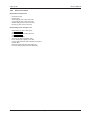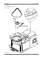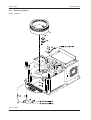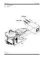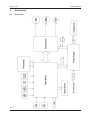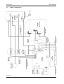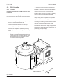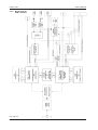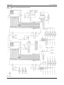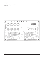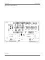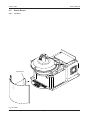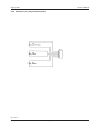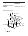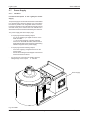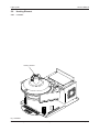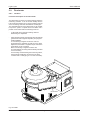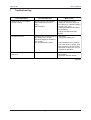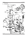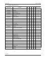
1
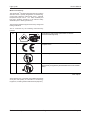
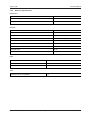
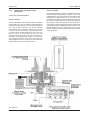
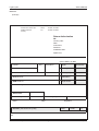
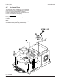
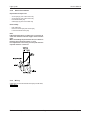
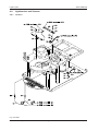
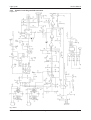
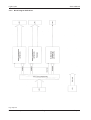
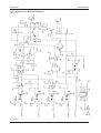
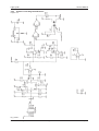
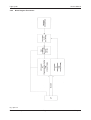
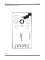
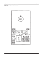
Service Manual
Light Cycler
Final 1.0 - January 1999
Light Cycler
Service Manual
Chapter
1
Application/Introduction
Chapter
2
Installation
Chapter
3
omitted
Chapter
4
Mechanics
Chapter
5
Electronics
Note: In some wiring diagrams the
fluorimeter is termed photometer !
Chapter
6
Software
Chapter
7
Trouble Shooting
Chapter
8
Spare Parts
Chapter
9
omitted
Chapter 10
Final 1.0 - January 1999
Maintenance
Light Cycler
1
Service Manual
Application/Introduction _________________________________ 2
1.1
LightCycler Workstation ______________________________________ 2
1.2
Technical Data ______________________________________________ 5
1.3
1.2.1
Instrument Specifications __________________________________________ 5
1.2.2
Application Specifications __________________________________________ 6
1.2.3
Detector Specifications ____________________________________________ 7
System Description __________________________________________ 8
1.3.1
1.4
The LightCycler ___________________________________________________ 8
Introduction _______________________________________________ 11
1.4.1
Instrument ______________________________________________________ 11
1.4.1.1 Principle of the LightCycler Technology ______________________________ 11
1.4.2
Instrument Components of the LightCycler ___________________________ 12
1.4.2.1 The Cycler Component _____________________________________________ 12
1.4.2.2 The Fluorimeter Component ________________________________________ 13
1.5
Warranty __________________________________________________ 14
Final 1.0 - January1999
Page 1
Chapter 1
Light Cycler
Service Manual
1
Application/Introduction
1.1
LightCycler Workstation
Contents of the Workstation
The LightCycler components are listed in the following
table:
Component
Description
System component 1
· LightCycler™ Instrument
· Sample Carousel (for Ø 1.5 mm capillary), premounted in LightCycler™
Instrument
System component 2
· Capillaries, (96 capillaries and caps/box)
· 32 Centrifuge adapters with 1 cooling block in an aluminium cooling block
· LightCycler™ Operator´s Manual
· Software Package
· Cable (to connect LC to computer)
· Power cord (German plug)
· Power cord (U.S. plug)
· Mouse Pad
Recommended PC Hardware /8/98 · Vectra VE4 5/200 MMX Model 3200 Desktop
· Intel Pentium MMX processor, 200 MHz
· 64 MB SDRAM DIMM
· 3.2 GB ultra-ATA/33 hard disk
· On-board PCI vide: S3 Trio 64 V2, 2MB 50 ns DRAM
· 24x speed DIE CD-ROM disk drive
· Keyboard and PS/2 mouse
Operating system
Windows NT 4.0, including service pack III
ZIP drive
Internal Iomega ZIP drive, DIE interface (ATAPI)
Monitor
HP Ergo 1280, 17" monitor (HP# D2840A)
Printer
HP Deskjet 890C Color Inkjet Printer
Tab.: cap1-1
Final 1.0 - January 1999
Page 2
Chapter 1
Light Cycler
Service Manual
Marks of Conformity
The LightCyclerTM has been manufactured in accordance
with EN 61010-1 (Safety Regulations for Measuring,
Control and Laboratory Instruments; Part 1: General
Requirements (IEC 1010-1 + A1: 1992, modified) and
has been checked according to all relevant safety
standards prior to leaving the factory.
The instrument has been approved for use by recognized
testing institutions.
This is confirmed by the following test/conformity
symbols:
GS
Certificated by VDE institute (Association of German
Electrotechnical Engineers)
CE
The instrument conforms to current directives as issued by the
European Union
UL
Certificated by Underwriters Laboratories Inc.
CUL
Certificated by Underwriters Laboratories for Canada – a
testing facility recognized by the Standards Council of Canada
(SSC)
Tab.: cap1-2
All equipment to be connected must fulfill the standards
set by IEC 950 (Safety of Information of Technology
Equipment, Including Electrical Business Equipment).
Final 1.0 - January1999
Page 3
Chapter 1
Light Cycler
Service Manual
Classification
-
ISM instrument, medium-sized, for industrial,
laboratory and domestic use.
The instrument is designed for stationary operation.
Any false measurements produced are irrelevant
from the safety point of view.
The instrument is designated for worldwide marketing.
It is intended for evaluating pre-processed biological
material.
The following should be noted:
- The instrument may not be used in conjunction with
infectious material without additional safety measures
being taken.
Final 1.0 - January 1999
Page 4
Chapter 1
Light Cycler
1.2
Technical Data
1.2.1
Instrument Specifications
Service Manual
General Data
Dimensions
Height 45 cm
Width 30 cm
Depth 45 cm
Weight
20 kg
Power supply
110-240 V ± 10%, 47-63 Hz
Wattage
800 W
Noise acc. to DIN 43635
< 80 dBA
Heat emission, including PC, monitor and printer
Max. 860 kcal/h
Safety symbols
CE, GS, UL, CSA or CUL
Tab.: cap1-3
Environmental Parameters
Temperature during operation
15 – 35°C
Temperature required during operation to maintain
specifications
15 – 30°C
Temperature during transport/storage/packaging
20 – 60°C
Relative humidity
20 – 80%
Altitude / pressure
0 – 2000 m above sea level1030 – 850 hp
Tab.: cap1-4
Samples
No. of samples
32
Sample volume
2 – 20 µl
Tab.: cap1-5
Final 1.0 - January1999
Page 5
Chapter 1
Light Cycler
1.2.2
Service Manual
Application Specifications
PCR Temperatures
Temperature range
40 – 98°C
Temperature accuracy of measuring system
± 0.3°C
Heating rate
Heating rate 40 – 95°C, step 40 – 95°C, time 10 – 90%
8s
Heating rate 50 – 72°C, step 50 – 72°C, time 10 – 90%
4s
Heating rate 72 – 98°C, step 72 – 95°C, time 10 – 90%
5s
Cooling rate
Cooling rate 95 – 40°C, step 95 – 40°C, time 10 – 90%
8s
Cooling rate 95 – 60°C, step 95 – 60°C, time 10 – 90%
4s
Temperature stability
Temperature stability with respect to time, 95°C
+1°C / -0.5°C range
Temperature stability with respect to time, 65°C
+1°C / -1.0°C range
Temperature stability with respect to time, 40°C
+1°C / -0.3°C range
Temperature homogeneity
Temperature homogeneity over all capillaries and time, 95°C
± 1.5°C range
Temperature homogeneity over all capillaries and time, 65°C
+ 0.7°C / -1.5°C range
Temperature homogeneity over all capillaries and time, 45°C
+ 1.5°C / -0.5°C range
Tab.: cap1-6
Temperature Gradients
Temperature gradient 0.1 °C/s, 0.2°C/s
Temperature homogeneity for one capillary, 70 – 95°C
± 1.5°C range
Temperature homogeneity for one capillary, 50 – 70°C
± 1.0°C range
Temperature homogeneity for one capillary, all positions, 70 – 95°C
± 2.0°C range
Temperature homogeneity for one capillary, all positions, 50 – 70°C
± 1.5°C range
Temperature gradient 1.0 °C/s
Temperature homogeneity for one capillary, 70 – 95°C
± 2.0°C range
Temperature homogeneity for one capillary, 50 – 70°C
± 2.0°C range
Temperature homogeneity for one capillary, all positions, 70 – 95°C
± 3.0°C range
Temperature homogeneity for one capillary, all positions, 50 – 70°C
± 3.0°C range
Temperature homogeneity for control of temperature peaks
Stability at 95°C for dynamic cycles, 72 – 95 – 50°C, 0s maintained
+2.0°C / -1.0°C range
Homogeneity of capillary /capillary at 95°C for dynamic cycles, 72 – 95 –
50°C, 0s maintained
+3.0°C / -1.0°C range
Temperature homogeneity in capillary
20 µl, 70°C
± 1.0°C range
15 µl, 70°C
± 0.5°C range
Tab.: cap1-7
Final 1.0 - January 1999
Page 6
Chapter 1
Light Cycler
1.2.3
Service Manual
Detector Specifications
Illumination
Type
LED
Median wavelength
470 nm
Output at 470 – 490 nm
0.1 mW
Tab.: cap1-8
Detector
Type
Photohybrid
Receptor surface
2.5* 2.5 mm²
Sensitivity at 520 nm, 20 µl sample volume
15 nM fluorescein (1s)
Sensitivity at 650 nm, 20 µl sample volume
x nM fluorescein /LightCycler Red 640
Sensitivity at 700 nm, 20 µl sample volume
x nM fluorescein / n.d.
Electronic dynamic
12 bit
Electronic bandwidth
1 kHz
Integration time
20 ms
Alteration of amplification range
Factor 1 – 256
Tab.: cap1-9
Filter
Detector 1
Bandpass 520 nm HBW 20 nm, dichroitic
Detector 2
Bandpass 645 nm HBW 30 nm, dichroitic
Detector 3
Bandpass 710 nm HBW 40 nm, dichroitic
Tab.: cap1-10
Time
Measuring time for 32 capillaries
< 5s
Tab.: cap1-11
Final 1.0 - January1999
Page 7
Chapter 1
Light Cycler
1.3
System Description
1.3.1
The LightCycler
Service Manual
Scheme of the Instrument
Fig. scheme1
Final 1.0 - January 1999
Page 8
Chapter 1
Light Cycler
Service Manual
Description of the Instrument
The sample capillaries are thermostatted with hot air in
the thermal chamber; a ventilator ensures efficient
aspiration, distribution and temperature homogeneity of
the air during the heating process. During the cooling
process, the ventilator operates at a higher speed in
order to ensure adequate cooling. A heating coil controls
the temperature.
For measurement, the sample rotor is propelled by a
stepper motor; this brings the capillary tip precisely to
the focal point of the photometer optics. The photometer
itself is placed in a radial position in relation to the signal
maximum in order to compensate for any radial deviation
of the capillary tip.
3 microprocessors incorporated in the instrument control
the process. Processor 1 is for communication, processor
2 regulates the temperature and processor 3 controls
the measurement procedure as well as the rotor and
photometer movements.
For online display, data are transmitted to the PC. Here,
sample data are entered, the PCR reaction temperature
is monitored, measurement modes and initial evaluation
of melting point temperatures are carried out.
Structure of the LightCycler
The instrument comprises a basic lower and an upper
unit.
Basic Lower Unit
Thermo-chamber, photometer, drive units, circuit boards and power supply are located in
the basic unit. The base of the unit is a 10 mm cast aluminum plate onto which the various
elements are fixed. This guarantees stability, especially for the thermo-chamber and
photometer.
Upper Unit
The upper unit contains the heating coil, an excess temperature sensor and a cooler with
sectional converter.
Tab.: cap1-12
Final 1.0 - January1999
Page 9
Chapter 1
Light Cycler
Service Manual
Thermo-Chamber Thermostatting
Thermostatting is done by using hot and cold air. A
sensor with thermal time constants identical with those
of the capillaries provides reference values for control
purposes. The process is controlled by varying the
heating coil voltage. During the heating phase, only the
ventilator in the thermo-chamber is in operation; this
guarantees a high degree of temperature homogeneity.
During the cooling phase, both the capillaries and the
heating coil must be cooled. The ventilator is then
operated at a higher speed.
2 sensors are incorporated in order to prevent excess
temperatures:
Sensor I
Sensor I is responsible for the temperature regulation.
Sensor II
Sensor II monitors the actual temperature.
Tab.: cap1-13
Fluorescence Photometer
A 3-channel fluorescence photometer is used for
detection purposes. Sample excitation is initiated by a
blue LED with an emission maximum of 470 nm.
Fluorescence is detected by means of a separate photohybrid for each wavelength.
Final 1.0 - January 1999
Page 10
Chapter 1
Light Cycler
1.4
Introduction
1.4.1
Instrument
Service Manual
1.4.1.1 Principle of the LightCycler Technology
System Description
The LightCycler comprises two different instrument
components: a cycler component and a fluorescence
detection component. The combination of both
components allows complex applications such as product
analysis, quantification and mutation analysis.
The cycler component has been optimized for rapid
PCR applications. Compared with classical PCR where
typical cycling programs take several hours, PCR
analyses carried out in the LightCycler can be completed
in only 15-30 min. This considerable time saving effect
is due to very short temperature transfer times, the socalled „ramping“ times, of the LightCycler instrument.
„Ramping“ times are the time periods necessary to
reach the next pre-set temperature of a „cycling“ protocol
in a PCR experiment. An example is the transition from
94°C to 55°C after sample denaturation for primer
hybridization during the annealing phase. This sort of
high-speed cycling is made possible by an optimized
surface / volume ratio of the samples and the use of air
as a temperature transfer medium.
Fluorimetric Detection
The combination of an optimized thermocycler and a
fluorimeter not only enables “online” presentation of the
PCR data obtained and efficient analysis of results, but
also offers the user utmost flexibility. To meet individual
requirements, different detection formats can be used
by choosing and combining fluorescent dyes and
detection probes.
Fluorimetric detection of the PCR products formed
consists of two different procedures:
- sequence-specific detection by the double stranded
DNA binding dye SYBRÒ Green I, or
- sequence-specific oligonucleotides are coupled to
suitable fluorophores as hybridization probes.
Analysis of Results
By means of the special LightCycler software, the data
obtained from fluorimetric analysis can be evaluated
and displayed. Additional cumbersome analytical
procedures subsequent to PCR, e.g. restriction and gel
analysis as well as blotting and hybridization experiments
are no longer necessary. The direct and simple analysis
of results also minimizes the contamination risk posed
by samples and working materials due to a reduction of
working steps required.
Final 1.0 - January1999
Page 11
Chapter 1
Light Cycler
1.4.2
Service Manual
Thermal Chamber
Instrument Components of the
LightCycler
1.4.2.1 The Cycler Component
Sample Carousel
The central element of the cylindrical thermal chamber
is the sample rotor. The rotor takes 32 samples in glass
capillaries with a diameter of 1.55 mm and a length of 35
mm. PCR analysis carried out in these specially
manufactured glass capillaries reduces the reaction
volume to only 5 to 20 ml max. The optimized surfaceto-volume ratio thus obtained allows for very short cycle
times of only 15 to 20 seconds per cycle. The very
favorable surface-to-volume ratio also guarantees an
extremely rapid temperature change in the reaction
mixture during each PCR cycle. At the same time, the
glass capillaries serve as cuvettes for the fluorimetric
determination of the PCR products formed.
The cylindrical thermal chamber is supplied with hot air
and air at ambient temperature by means of a fan with
coupled heating coils. The incoming air is homogeneously
distributed by a high-velocity fan at the base of the
instrument, thus creating an even temperature throughout
the reaction chamber. Surplus air is vented through an
opening at the side of the chamber. The temperature is
controlled by using an integrated measuring system with
a temperature sensor installed in the direct vicinity of the
sample capillaries of the sample carousel. The PCR
thermal chamber is directly coupled to the optical system
of the fluorimeter.
Fig. scheme1
Final 1.0 - January 1999
Page 12
Chapter 1
Light Cycler
Service Manual
1.4.2.2 The Fluorimeter Component
Optics
The fluorescent optical components of the LightCycler
are schematically illustrated in chapter 1.3.1 The Light
Cycler. A blue high-performance diode (blue LED) serves
as energy source for sample excitation. The diode emits
radiation which is spectrally filtered to a wavelength of
470 nm and an energy of 1 mW and is collimated
(brought to the same wavelength) by means of a special
optical system. The homogeneous light beam of 470 nm
generated is subsequently focused onto the individual
glass capillaries and then onto the samples to be
measured in the sample carousel. The glass capillaries
are moved by a high-precision stepper motor and placed
in the optimal position for excitation and measurement.
According to the spectral properties of the fluorophore
used, the light emitted from the excited samples is
guided into one of three channels (see drawing in
chapter 1.3.1 The Light Cycler) via dichroitic mirrors for
subsequent evaluation. In this channel, the emitted light
beam is further collimated and spectrally concentrated
by means of a special filter optical system. For final
evaluation, the light beam is then focused onto a
photomultiplier.
The three evaluation channels of the LightCycler are
fitted with filter combinations. Thus, analysis at the given
emission wavelengths is possible and exact sample
measurement can be carried out in parallel with the
fluorophores given in Tab.: cap 1-14:
Fluorophore
Fluorescein
SYBR Green I
LC-Red 640*
Excitation Channel
Analysis Channel
1
2
3
470 nm±40
530 nm±20
640 nm±20
710 nm±40
490 nm
494 nm
525 nm
521 nm
640 nm
Tab.: cap1-14
Table cap 1-14
Specification of excitation and measuring channels of
the fluorimeter component of the Roche Diagnostics
LightCycler: Comparison of the spectral properties of
selected fluorophores.
Abbreviations *: LC-Red = Light CyclerTM -Red 640
**
: LC-Red is not excited by the blue LED, but is a FRET
partner of fluorescein.
For further information, refer to the Operating Manual.
Final 1.0 - January1999
Page 13
Chapter 1
Light Cycler
1.5
Service Manual
Repairs
Warranty
As a general rule, all instrument repairs should be
carried out by authorized and trained personnel only.
Processing of Warranty Claims
A warranty claim has to be processed by way of the
Return Authorization procedure or any accepted
equivalent. Please answer all the questions on the RA
form with the greatest care.
The warranty claim will only be accepted by the
manufacturer if a detailed fault description is supplied.
Complete instruments are accepted only in agreement
with the Technical Product Management or with the
responsible person of Roche Diagnostics Technical
Support.
Important Information:
-
Only parts marked with „A“ in the price list are
generally accepted under warranty.
-
Return only parts marked with „R“ in the spare parts
price list.
-
Warranty claim for “R” parts will be accepted, if the
part has been returned to Mannheim.
-
All defective parts ( non-“R“ and „A“ parts ) should
be kept for a period of 7 months, should the
manufacturer need to investigate the part, in which
case it will be requested.
-
All parts unduly returned to Mannheim will be sent
back at the expense of each country's respective
service center.
-
RA warranty claims are accepted no later than 8
weeks after the problem date.
Parts which are worth repairing are marked with „R“ in
the spare parts price list. New and repaired parts can
be distinguished from each other by different material
numbers (language version).
(e.g. new part: 1234567-001, repaired part: 1234567984)
Repaired parts should be ordered together with new
parts via the order processing department in Mannheim (OU-VDG). Defective parts should be returned
together with order of repair, including the filled out
RA form (giving full details of the defect and marked
choice box with repair), to Logistic Instruments
(Incoming Goods) in Mannheim-Wohlgelegen (LI-LV).
Repair of Instruments
Complete instruments are accepted only, if the
problem is definitety located in the photometer unit.
The replacement should have been agreed with the
Technical Product Management or with the
responsible person of the Roche Diagnostics
Technical Support.
Terms of Delivery
Shipments to countries with the routine truck are c.i.f./
other shipments are ex works Mannheim .
Emergency shipments incur additional charges.
Exclusion from Warranty
The aforementioned warranties do not apply in case of
improper use, handling, transportation or storage, faulty
installation, repair or maintenance, chemical influence
or contamination as well as damages resulting from that,
failure to follow operating instructions, alterations or
modifications of instruments or parts thereof not
authorized or recommended by Roche Diagnostics and
resulting damages, normal wear and tear and in case of
other circumstances beyond the control of Roche
Diagnostics.
Final 1.0 - January 1999
Repair of Parts Marked with „R“
Charges
"Repaired" parts (material no. 1234567-984) are
supplied at a "repair price. There will be a subsequent charge consisting of the price difference
between a new and repaired part, should the
defective parts not be returned within 3 weeks (for
European countries) and 8 weeks (for Overseas
countries).
Page 14
Chapter 1
Light Cycler
Service Manual
After receipt of a warranty claim for “A” parts, BMG
will credit 100 % of the currently effective ex MA price.
In case the manufacturer does not accept the
warranty claim, each country's respective service
center will be charged the R-price for "R" parts and
the new price for non "R" parts.
RA Form
Return Authorization
Please answer all the questions on the RA form with
the greatest care and sign the form.
-
Country code
Problem date
Type of instrument
Serial no. of the instrument
Installation date of instrument
Defective instrument or spare part
Part number and material number of the spare
part
Old / new serial no.
Fault description
Alarm code
Service / workshop report no.
Instruments Not Under Warranty
- Installation date of spare part
All returned parts should be individually labeled with
the corresponding RA no. and shipped together with
the completed RA form to:
Roche Diagnostics
Logistic Instruments
RA Management
Friedrich Ebert Str. 100
D - 68167 Mannheim
Germany
Final 1.0 - January1999
Page 15
Chapter 1
Light Cycler
Service Manual
RA Form
(Example)
ROCHE DIAGNOSTICS GmbH
Friedrich-Ebert-Strasse 100
D-68167 Mannheim
Germany
Telefon :
Fax :
+49 (621) 759 81 84
+49 (621) 759 80 93
Return Authorization
No.:
Country code:
Date:
Instrument:
Serial No.:
Installation date:
Spare Part:
Customer:
Address:
(will be filled in by BM)
Part No.:
Qty.:
Part Name:
Repair
Comments
Mat.-No.:
Warranty
Installation date of Spare Part:
Warranty Repair
OLD serial No.:
Modification
NEW serial No.:
Replacement
Fault Description:
Alarm Code:
Service Report No.:
Place:
Workshop Report No.:
Date:
Signature:
Remarks (will be filled in by BM)
NOS
Credit
FC
BM
Final 1.0 - January 1999
Page 16
Chapter 1
Light Cycler
2.
Service Manual
Installation _____________________________________________ 2
2.1
Installation Requirements ____________________________________ 2
2.2
Installation of the LightCycler _________________________________ 4
2.3
Computer and Software Installation ____________________________ 5
2.4
LightCycler De-installation ____________________________________ 6
2.5
Operation and Maintenance of the LightCycler ___________________ 7
Final 1.0 - January 1999
Page 1
Chapter 2
Light Cycler
Service Manual
2.
Installation
2.1
Installation Requirements
Note
-
-
The LightCycler should not be set up next to
instruments that cause electromagnetic
interference or have high inductance, e.g.
centrifuges or mixers.
All connected peripheral instruments must fulfill
the requirements of Standard IEC 950 (UL 1950).
All plugs used in the LightCycler workstation (PC,
printer, monitor) should have the same phasing in
order to prevent switch-on peaks and electronic
noise generated by other instruments or the power
supply itself. Use of an appropriate distributor plug
with the LightCycler workstation is recommended.
Working Place Requirements
See the following table for the working place
requirements:
Dimensions and weight
The LightCycler has a width of 30 cm, a depth of 45 cm and a height of 45 cm.
It weighs approximately 20 kg.
Voltage requirements
The LightCycler operates on 120 – 240 V (50 – 60 Hz) and need not be
adjusted.
Power consumption
The LightCycler requires approximately 800 W; PC and printer require a further
500 W.
Tab.: cap2-1
The LightCycler must not be opened by the
user
The fuse may only be replaced if the instrument
has been switched off at the mains.
Environmental Requirements
Please refer to the following table for the environmental
requirements:
Ambient temperature
15 – 35 °C (all specifications maintained between 15 and 30°C)
Humidity
20 – 80 %, no condensation
Altitude
Sea level to 2000 m
Excess voltage
category II
Degree of contamination
2
Tab.: cap2-2
Final 1.0 - January 1999
Page 2
Chapter 2
Light Cycler
Service Manual
Storage Conditions
The LightCycler™ can be stored on5 the following
conditions:
Ambient temperature
-20 - +60°C
Humidity
20 – 80%, no condensation
Tab.: cap2-3
Final 1.0 - January 1999
Page 3
Chapter 2
Light Cycler
2.2
Service Manual
Installation of the LightCycler
Installation of the Instrument
Please refer to the following table for the installation of
the LightCycler instrument:
Step
Action
1
Unpack the instrument.
2
Position instrument on bench, working surface. Allow 10 cm space left, right and behind.
3
Electrical connections:
- Connect LightCycler to the PC using an R 232 cable (serial inter-face).
- Connect LightCycler, PC, monitor and printer to same distributor plug.
Tab.: cap2-4
Ensure that printer, monitor and PC have
been set to the correct voltage.
Final 1.0 - January 1999
Page 4
Chapter 2
Light Cycler
2.3
Service Manual
Computer and Software
Installation
Installation of the PC
After unpacking the computer, carry out the following
steps:
Step
Action
1
Connect mouse, keyboard and monitor to the computer.
2
Connect the LightCycler to the computer with an R 232 cable (serial interface).
3
Connect computer, monitor and LightCycler to the distributor plug.
The computer is now ready for operation
Tab.: cap2-5
Software
The complete software package is installed by Roche
Diagnostics.
Installation of Updates / Reinstallation
In the following table you find information about the
reinstallation and loading of updates:
Step
Action
1
Store any data, e.g. DATA, PROFILES and PROTOCOLs
2
Place LightCycler CD-ROM in appropriate disk drive (e.g. F)
3
Start set-up program (e.g. F:\SETUP.EXE).
Tab.: cap2-6
Final 1.0 - January 1999
Page 5
Chapter 2
Light Cycler
2.4
Service Manual
LightCycler De-installation
De-installation of the Instrument
Please refer to the following table for the de-installation
of the instrument:
Step
Action
1
Switch off the instrument.
2
- Disconnect the RS 232 and power cables.
- Clean according to the chapter on service and decontaminate if necessary.
3
Dispatch instrument in its original packaging.
Tab.: cap2-7
Final 1.0 - January 1999
Page 6
Chapter 2
Light Cycler
2.5
Service Manual
Operation and Maintenance of
the LightCycler
Guidelines for Operation
-
-
-
-
The instrument may be operated only if protected
from the weather. It may not be operated in
buildings without temperature regulation facilities.
If necessary, additional drying agents may be
used to eliminate humidity.
The instrument should not be operated near
dripping, spraying, splashing or running water.
The instrument is thus suitable for use according
to classification 3K3 in accordance with Standard
EN 60721-3-3.
The instrument may be used at locations subject
to noticeable or significant vibration; however, it
should not be exposed to higher levels of shock
waves.
The instrument is thus suitable for use according
to classification 3M4 in accordance with Standard
EN 60721-3-3. The instrument is able to tolerate
vibrations up to classification 3M6. However,
based on expected locations of use, no significant
and permanent vibrations or shock waves are to
be expected.
Transport and Storage
When storing or transporting the instrument, it should
not be exposed to extreme cold, e.g. as in the case of air
freight. Temperatures lower than –25°C should be
avoided (damage to optical systems). The optical
systems are equipped with open ventilation systems
and should therefore be protected from dirt and humidity.
There are no further specifications for transport and
storage.
General Maintenance
The instrument is maintenance-free.
Cleaning the Instrument
-
Use 70% ethanol for disinfecting the incubator.
Use only alcohol and an optical cloth for cleaning
the optical window.
Use a mild commercial detergent for domestic use
for cleaning the housing.
Final 1.0 - January 1999
Page 7
Chapter 2
Light Cycler
4
Service Manual
Mechanics _____________________________________________ 3
4.1
Overview __________________________________________________ 3
4.2
Disassembly of the Housing Parts _____________________________ 4
4.2.1
Housing Lid ______________________________________________________ 4
4.2.2
Housing _________________________________________________________ 6
4.2.3
Panel ____________________________________________________________ 8
4.3
Sample Rotor and Fan Wheel _________________________________ 10
4.4
Heating Element ___________________________________________ 12
4.5
Chamber Lid_______________________________________________ 14
4.6
Rotor _____________________________________________________ 16
4.6.1
Stepper Motor Rotor ______________________________________________ 16
4.6.2
Fan Motor _______________________________________________________ 18
4.6.3
Measuring Chamber ______________________________________________ 20
4.7
Fluorimeter Drive ___________________________________________ 22
4.8
Lightbarriers and Sensors ___________________________________ 24
4.8.1
Location ________________________________________________________ 24
4.8.2
Rotor Lightbarrier ________________________________________________ 25
4.8.3
Interlock Lightbarrier _____________________________________________ 25
4.8.4
Fluorimeter Lightbarrier ___________________________________________ 26
4.8.5
Monitor Temperature Sensor _______________________________________ 26
4.8.6
Control Temperature Sensor _______________________________________ 27
4.8.7
Excess Temperature Switch ________________________________________ 27
Final 1.0 - January 1999
Page 1
Chapter 4
Light Cycler
Service Manual
4.9
Power Supply ______________________________________________ 28
4.9.1
Location ________________________________________________________ 28
4.10 PCBs _____________________________________________________ 30
4.10.1 Location ________________________________________________________ 30
4.10.2 PCB Controller und Battery ________________________________________ 31
4.10.3 PCB Driver ______________________________________________________ 31
4.10.4 Status Board ____________________________________________________ 31
Final 1.0 - January 1999
Page 2
Chapter 4
Light Cycler
4
Mechanics
4.1
Overview
Service Manual
Fig. 160798k1
Final 1.0 - January 1999
Page 3
Chapter 4
Light Cycler
4.2
Disassembly of the Housing
Parts
4.2.1
Housing Lid
Service Manual
4.2.1.1 Location
Fig. 140798k2
Final 1.0 - January 1999
Page 4
Chapter 4
Light Cycler
Service Manual
4.2.1.2 Service Procedure
Replaceable Components:
-
Housing lid (1) (is part of the housing set)
Screw (2) (is part of the screw set)
Gasket (61)
Disassembly of the Housing Cover:
-
Flap housing lid (1) backwards
Remove all screws (2)
Remove housing lid (1)
Disassembly of Gasket:
-
Flap housing lid (1) backwards
Remove gasket (61).
Final 1.0 - January 1999
Page 5
Chapter 4
Light Cycler
4.2.2
Service Manual
Housing
4.2.2.1 Location
Fig. 151298k1
Final 1.0 - January 1999
Page 6
Chapter 4
Light Cycler
Service Manual
4.2.2.2 Service Procedure
Replaceable Components:
-
Housing (3) (is part of the housing set)
Screw (4) (is part of the srew set)
Washer (5) (is part of the screw set)
Disassembly of the Housing:
-
Remove all the screws (4) with washers (5)
Lift off housing (3)
Note:
Please take care that the edges of the cover (3) do not
scratch the front of the cover (3)
Final 1.0 - January 1999
Page 7
Chapter 4
Light Cycler
4.2.3
Service Manual
Panel
4.2.3.1 Location
Fig. 140798k1
Final 1.0 - January 1999
Page 8
Chapter 4
Light Cycler
Service Manual
4.2.3.2 Service Procedure
Replaceable Components:
-
Screws (6) (are part of the screw set)
Washers (7) (are part of the screw set)
Panel (8) (is part of the housing set)
Status board (9)
Washers (10) (are part of the screw set)
Nut (11) (is part of the screw set)
Cable (12) (is part of the cable set)
Disassembly of the Panel:
-
Remove housing,
see chapter 4.2.2
Loosen all screws (13)
Remove all the screws (6) with washers (7)
Pull cable (12)
Lift chamber lid (14)
Take off panel (8)
Disassembly of the Status Board:
-
Disassemble the panel (8)
Remove nuts (11) with washers (10)
Remove status board (9)
4.2.3.3 Wiring
Cable (12) connects status board (9) to PCB controller
JP12, see chapter 4.10.4
Final 1.0 - January 1999
Page 9
Chapter 4
Light Cycler
4.3
Sample Rotor and Fan Wheel
4.3.1
Location
Service Manual
Fig. 140798k7
Final 1.0 - January 1999
Page 10
Chapter 4
Light Cycler
4.3.2
Service Manual
Service Procedure
Replaceable Components:
-
Sample rotor (13)
Fan wheel (15)
Disassembly of the Sample Rotor:
-
Flap housing lid (1) backwards
Remove sample rotor (13)
Disassembly of Fan Wheel:
-
Disassemble the sample rotor (13)
Remove nut (14)
Remove fan wheel (15) by lifting it out
Note:
Do not tighten nut (14) too tight when mounting the fan
wheel (15), or this might cause damage to the plastic fan
motor thread.
Final 1.0 - January 1999
Page 11
Chapter 4
Light Cycler
4.4
Heating Element
4.4.1
Location
Service Manual
Fig. 150798k1
Final 1.0 - January 1999
Page 12
Chapter 4
Light Cycler
4.4.2
Service Manual
Service Procedure
Replaceable Components:
-
Heating element (16)
Cable (17) (is part of the cable set)
Ground cable (29) (is part of the cable set)
Disassembly of the Heating Element:
-
Flap housing lid (1) backwards,
see chapter 4.2.1
Disassemble the housing (3),
see chapter 4.2.2
Remove screw (23) with washer (24)
Remove cable clip (25) with washer (26)
Remove cable (17) from cable clip (25)
Remove screws (18)
Remove screw (19)
Pull off cover sheet (20)
Pull cable (17)
Remove heating element (16) by lifting it out
Remove sheathing (21) if necessary
Disassembly of the Flange:
-
Disassemble the heating element (16)
Remove screw (23)
Remove flange (22) by lifting it out
Disassembly of the Grounding:
-
Remove screw (27) with washer (28)
Remove grounding (29)
4.4.3
Wiring
Cable (17) connects heating element (16) to power
supply, see chapter 4.9
Ground cable (29) connects base plate (30) to lower part
of the housing (31)
Final 1.0 - January 1999
Page 13
Chapter 4
Light Cycler
4.5
Chamber Lid
4.5.1
Location
Service Manual
Fig. 140798k3
Final 1.0 - January 1999
Page 14
Chapter 4
Light Cycler
4.5.2
Service Manual
Service Procedure
Replaceable Components:
-
Chamber lid (33)
Damper (84)
Screw (34) (is part of the screw set)
Screw (35) (is part of the screw set)
Washer (85) (is part of the screw set)
Nut (65) (is part of the screw set)
Disassembly of the Chamber Lid:
-
Disassembly of the housing parts,
see chapter 4.2
Disassembly of the heating element,
see chapter 4.4
Remove screws (34)
Remove nut (86) and washer (85)
Push damper (84) slightly to the side
Lift out base plate (36) with chamber lid (33) and
damper (84)
Remove screws (35) and base plate (36)
Unscrew damper (84) from base plate (36)
Final 1.0 - January 1999
Page 15
Chapter 4
Light Cycler
4.6
Rotor
4.6.1
Stepper Motor Rotor
Service Manual
4.6.1.1 Location
Fig. 151298k2
Final 1.0 - January 1999
Page 16
Chapter 4
Light Cycler
Service Manual
4.6.1.2 Service Procedure
Replaceable Components:
-
Stepper motor rotor (43)
Tooth belt (42)
Cable (38) (is part of the cable set)
Screw (39) (is part of the screw set)
Washer (40) (is part of the screw set)
Set screw (41) (is part of the screw set)
Disassembly of the Tooth Belt:
-
Disassembly of the housing parts,
see chapter 4.2
Disassembly of the heating element,
see chapter 4.4
Disassembly of the chamber lid,
see chapter 4.5
Pull cable (38) from PCB driver
Remove screws (39) and washers (40)
Turn set screw (41) in order to reduce tooth belt (42)
tension
Lift out tooth belt (42)
Fig. 030898k1
Fix the fixation srews (39) of the stepper motor (43) and
check again for proper movement.
Disassembly of the Stepper Motor Rotor:
-
Disassembly of the tooth belt
Lift out stepper motor rotor (43)
4.6.1.3 Wiring
Cable (38) connects stepper motor rotor (43) to PCB
driver, see chapter 4.10.3
4.6.1.4 Adiustments
Belt tension of the sample rotor drive
An adjustment of the belt tension is necessary if one of
the following components is removed or replaced:
- stepper motor (rotor) (43)
- tooth belt (42)
- measuring chamber (47)
Proper adjustment of the belt tension ensures a minimum
of friction between motor, belt and rotor.
To adjust the belt tension, please proceed as follows:
- Open the fixation screws (39) of the stepper motor
(rotor) (43) about 1/4 of a turn, so that the motor can
be moved in a horizontal direction
- Adjust the tension with the adjustment screw (41) until
the teeth of the belt fit properly into the grooves of the
rotor drive, see drawing
Final 1.0 - January 1999
Page 17
Chapter 4
Light Cycler
4.6.2
Service Manual
Fan Motor
4.6.2.1 Location
Fig. 151298k3
Final 1.0 - January 1999
Page 18
Chapter 4
Light Cycler
Service Manual
4.6.2.2 Service Procedure
Replaceable Components:
-
Fan motor (44)
Screw (45) (is part of the screw set)
Cable (46) (is part of the cable set)
Cable (92) (is part of the cable set)
Disassembly off the Fan Motor:
-
Disassembly of the housing parts,
see chapter 4.2
Disassembly of the sample rotor and fan wheel,
see chapter 4.3
Pull cable (46)
Pull cable (92)
Remove screws (45)
Remove fan motor (44) by pulling it in a downward
direction
4.6.2.3 Wiring
Cable (46) and calbe (92) connects fan motor (44) to PCB
driver, see chapter 4.10.3
4.6.2.4 Adjustmemt
When assembling the heat dissipator of the fan motor
(44), it is important that its edge is parallel to that of the
fluorimeter.
Please ensure that the dissipator does not touch the
fluorimeter.
Fig. 030898k1
Final 1.0 - January 1999
Page 19
Chapter 4
Light Cycler
4.6.3
Service Manual
Measuring Chamber
4.6.3.1 Location
Fig. 140798k8
Final 1.0 - January 1999
Page 20
Chapter 4
Light Cycler
Service Manual
4.6.3.2 Service Procedure
Disassembly of the Rotor Lightbarrier:
Replaceable Components:
-
-
Measuring chamber (47)
Glass window for fluorimeter (56)
Screw (52) (is part of the screw set)
Washer (53) (is part of the screw set)
Cable (48) (is part of the cable set)
Cable (49) (is part of the cable set)
Control temp. sensor (50)
Monitor temp. sensor (51)
Pull cable (60)
Remove screws (57) and washers (58)
Lift out rotor lightbarrier (59)
4.6.3.3 Wiring
Disassembly of the Measuring Chamber and Glass
Window for the Fluorimeter:
Cable (48) connects control temp. sensor (50) to PCB
controller, see 4.10.2.
Cable (49) connects monitor temp. sensor (51) to PCB
controller, see 4.10.2.
Cable (60) connects rotor lightbarrier (59) to PCB
controller, see 4.10.2.
-
4.6.3.4 Adjustment
-
Disassembly of the housing parts,
see chapter 4.2
Disassembly of the sample rotor and fan wheel,
see chapter 4.3
Disassembly of the heating element,
see chapter 4.4
Disassembly of the chamber lid,
see chapter 4.5
Disassembly of the tooth belt,
see chapter 4.6.1
Disassembly of the fan motor,
see chapter 4.6.2
Pull cable (48) and cable (49)
Unscrew control temp. sensor (50)
Unscrew monitor temp. sensor (51)
Remove screws (52) and washers (53)
Lift out measuring chamber (47)
Remove spring washer (54)
Remove glass window (55)
see chapter 4.8.6.1
Attention:
Do not touch the window (55) with your fingers!
A fingerprint would generate an additional flourecence
signal, which would affect the measurement results!
Carefully clean the window (55) with 70% ethanol,
polishing it with a lint-free tissue afterwards.
Assembly of the Window:
- Please use the new spring washer (54) in case of a
window (55) replacement
- Ensure that the window (55) is placed in the
correct position
Fig. 040898k1
Final 1.0 - January 1999
Page 21
Chapter 4
Light Cycler
4.7
Service Manual
Fluorimeter Drive
The fluorimeter (65) is preadjusted by the manufacturer
and is adjusted for the second time when it is assembled
in the Light Cycler production plant in Germany.
In case of a defective fluorimeter, the complete instrument
is to be sent to Mannheim for repairing.
Please use the RA procedure for the shipment to Mannheim, see chapter 1.5
The repaired instruments will be sent to you as soon as
possible.
Note:
Please do not touch any of the fluorimeter (65)
adjustment screws (especially focus screws).
4.7.1
Location
Fig. 150798k2
Final 1.0 - January 1999
Page 22
Chapter 4
Light Cycler
4.7.2
Service Manual
Service Procedures
Replaceable Components:
-
Screw (62) (is part of the screw set)
Screw (64) (is part of the screw set)
Fluorimeter drive (64)
Cable (66) (is part of the cable set)
Disassembly:
-
Pull cable (66)
Remove screws (62) and screws (63)
Lift out fluorimeter drive (64)
Note:
If the fluorimeter drive is replaced, it is necessary to
check the distance between stepper motor and the
plate.
When assembling the photometer drive, the distance
between them should be 18mm +/- 1mm.
If an adjustment is necessary, turn the plate until the
required distance is reached.
4.7.3
Wiring
Cable (66) connects fluorimeter drive (64) to PCB driver,
see 4.10.3.
Final 1.0 - January 1999
Page 23
Chapter 4
Light Cycler
4.8
Lightbarriers and Sensors
4.8.1
Location
Service Manual
Fig. 150798k3
Final 1.0 - January 1999
Page 24
Chapter 4
Light Cycler
4.8.2
Service Manual
Rotor Lightbarrier
4.8.3
The rotor lightbarrier monitirs the rotations of the rotor.
Interlock Lightbarrier
The interlock lightbarrier is a reflection lightbarrier. It
senses whether the housing lid is open or closed.
Replaceable Components:
Replaceable Components:
-
Rotor lightbarrier (59)
Screw (57) (is part of the screw set)
Washer (58) (is part of the screw set)
Cable (60) (is part of the cable set)
-
Interlock lightbarrier (66)
Screw (68) (is part of the screw set)
Washer (67) (is part of the screw set)
Cable (69) (is part of the cable set)
Disassembly:
Disassembly:
-
Disassembly of the housing parts,
see chapter 4.2
Disassembly of the sample rotor and fan wheel,
see chapter 4.3
Disassembly of the heating element,
see chapter 4.4
Disassembly of the chamber lid,
see chapter 4.5
Disassembly of the tooth belt,
see chapter 4.6.1
Pull cable (60)
Remove screw (57) and washer (58)
Lift out rotor lightbarrier (59)
-
Disassembly of the housing,
see chapter 4.2.2
Pull cable (69)
Remove screw (68) and washer (67)
Lift out interlock lightbarrier (66)
4.8.3.1 Wiring
Cable (66) connects interlock lightbarrier (66) to PCB
controller, see chapter 4.10.2
4.8.2.1 Wiring
Cable (60) connects rotor lightbarrier (59) to PCB
controller, see chapter 4.10.2
Final 1.0 - January 1999
Page 25
Chapter 4
Light Cycler
4.8.4
Service Manual
Fluorimeter Lightbarrier
4.8.5
Monitor Temperature Sensor
The fluorimeter lightbarrier monitirs the fluorimeter
movements.
The monitor temperature sensor monitors the measuring
chamber temperature and prevents excess temperature.
Replaceable Components:
Replaceable Components:
-
-
Fluorimeter lightbarrier (70)
Screw (72) (is part of the cable set)
Washer (71) (is part of the screw set)
Cable (73) (is part of the cable set)
Disassembly:
Disassembly:
-
-
-
-
Monitor temperature sensor (51)
Cable (49) (is part of the cable set)
Disassembly of the housing,
see chapter 4.2.2
Pull cable (73)
Remove screw (72) and washer (71)
Lift out fluorimeter lightbarrier (70)
Disassembly of the panel,
see chapter 4.2.3
Pull cable (49)
Unscrew monitor temperature sensor (51)
4.8.5.1 Adjustment
see chapter 4.8.6.1
4.8.4.1 Wiring
Cable (73) connects fluorimeter lightbarrier (70) to PCB
controller, see chapter 4.10.2
4.8.5.2 Wiring
Cable (49) connects monitor temperature sensor (51) to
PCB controller, see chapter 4.10.2.
Final 1.0 - January 1999
Page 26
Chapter 4
Light Cycler
4.8.6
Service Manual
Control Temperature Sensor
4.8.7
The control temperature sensor controls excess
temperature in the measuring chamber.
Excess Temperature Switch
The excess temperature switch is a bimetal switch which
protects the Light Cycler from overheating, e.g due to
excess periods of operation.
Replaceable Components:
Replaceable Components:
-
Control temperature sensor (50)
Cable (48) (is part of the cable set)
-
Disassembly:
-
Disassembly of the panel,
see chapter 4.2.3
Pull cable (48)
Unscrew control temperature sensor (50)
Excess temperature switch (74)
Screw (76) (is part of the screw set)
Washer (75) (is part of the screw set)
Cable (77) (is part of the cable set)
Disassembly:
-
4.8.6.1 Adjustment
Disassembly of the housing,
see chapter 4.2.2
Pull cable (77)
Remove screw (76) and washer (75)
Lift out excess temperature switch (74)
Temperature Sensors
Two temperature sensors for temperature control and
temperature monitoring are located in the measuring
chamber of the light cycler. The sensors should be placed
close to the capillaries in the sample rotor so that the
temperature can be monitored as accurately as possible.
However, the sensors must not touch the capillaries
when the rotor is moving.
For this reason, the height of these sensors needs to be
adjusted.
4.8.7.1 Wiring
Cable (77) connects excess temperature switch (74) to
PCB controller, see chapter 4.10.2
See drawing below:
Fig. 030898k1
The height can be adjusted by turning the sensor fixation
screws clockwise or counterclockwise.
4.8.6.2 Wiring
Cable (48) connects control temperature sensor (50) to
PCB controller, see chapter 4.10.2.
Final 1.0 - January 1999
Page 27
Chapter 4
Light Cycler
4.9
Power Supply
4.9.1
Location
Service Manual
Fig. 230998k1
Final 1.0 - January 1999
Page 28
Chapter 4
Light Cycler
4.9.2
Service Manual
Service Procedure
Replaceable Components:
-
Power supply (81)
Cable (17) (is part of the cable set)
Cable (90) (is part of the cable set)
Cable (91) (is part of the cable set)
Screw (88) (is part of the screw set)
Screw (89) (is part of the screw set)
Disassembly of the Power Supply:
-
Disassembly of the housing parts,
see chapter 4.2
Pull cable (17)
Pull cable (90)
Pull cable (91)
Remove screws (88)
Remove screw (89)
Pull out the power supply (81)
4.9.3
Wiring
Cable (17) connects power supply (81) to heating element,
see chapter 4.4.
Cable (90) connects power supply (81) to PCB controller,
see chapter 4.10.2.
Cable (91) connects power supply (81) to PCB driver, see
chapter 4.10.23
Final 1.0 - January 1999
Page 29
Chapter 4
Light Cycler
Service Manual
4.10 PCBs
4.10.1 Location
Fig. 100898k1
Final 1.0 - January 1999
Page 30
Chapter 4
Light Cycler
Service Manual
4.10.2 PCB Controller und Battery
4.10.4 Status Board
The PCB controller of the Light Cycler houses the essential control functions, data recording and communication
with the PC via interface RS232.
was macht dieses?
Replaceable Components:
-
-
-
PCB controller (78)
Battery (79)
Disassembly:
Disassembly of the panel (8)
see chapter 4.2.3
Remove nuts (11) with washers (10)
Remove status board (9)
Pull cable (12)
Disassembly of the PCB Controller:
-
Disassembly of the housing,
see chapter 4.2.2
Pull all the connecting cables from the PCB controller
(78)
Remove the PCB controller (78) located on the side
4.10.4.1 Wiring
Cable (12) connects status board (9) to PCB controller
JP12, see chapter 4.10.2
Disassembly of the Battery:
-
Disassembly of the housing,
see chapter 4.2.2
Remove battery (79) from the PCB controller (78)
4.10.2.1 Wiring
Aufzählung der Kabel, die zum PCB Controller gehen!
4.10.3 PCB Driver
was macht dieses?
Replaceable Components:
-
PCB Driver (80)
Screws (82) (are part of the screw set)
Washers (83) (are part of the screw set)
Disassembly:
-
Disassembly of the housing,
see chapter 4.2.2
Pull all the connecting cables from the PCB driver (80)
Remove screws (82) and washers (82)
Lift out PCB driver (80)
4.10.3.1Wiring
Aufzählung der Kabel, die zum PCB Controller gehen!
Final 1.0 - January 1999
Page 31
Chapter 4
Light Cycler
5
Service Manual
Electronics ____________________________________________ 3
5.1
Overview __________________________________________________ 3
5.2
Cable Connections __________________________________________ 4
5.3
PCB Controller ______________________________________________ 5
5.4
5.5
5.6
5.3.1
Location _________________________________________________________ 5
5.3.2
Block Diagram PCB Controller ______________________________________ 6
5.3.3
Printed Circuit Diagram PCB Controller _______________________________ 7
5.3.4
Layout Diagram PCB Controller ____________________________________ 11
PCB Driver ________________________________________________ 13
5.4.1
Location ________________________________________________________ 13
5.4.2
Block Diagram PCB Driver _________________________________________ 14
5.4.3
Printed Circuit Diagram PCB Driver _________________________________ 15
5.4.4
Layout Diagram PCB Driver ________________________________________ 18
Status Board ______________________________________________ 20
5.5.1
Location ________________________________________________________ 20
5.5.2
Printed Circuit Diagram Status Board ________________________________ 21
5.5.3
Layout Diagram Status Board ______________________________________ 22
Lightbarriers and Sensors ___________________________________ 23
5.6.1
5.7
Location ________________________________________________________ 23
Power Supply ______________________________________________ 24
5.7.1
Location ________________________________________________________ 24
Final 1.0 - January 1999
Page 1
Chapter 5
Light Cycler
Service Manual
5.8
Heating Element ___________________________________________ 25
5.8.1
5.9
Location ________________________________________________________ 25
Fluorimeter ________________________________________________ 26
5.9.1
Location ________________________________________________________ 26
5.9.2
Block Diagram Fluorimeter ________________________________________ 27
5.9.3
Printed Circuit Diagram PCB Fluorimeter_____________________________ 28
5.4.4
Layout Diagram PCB Fluorimeter ___________________________________ 29
Final 1.0 - January 1999
Page 2
Chapter 5
Light Cycler
5
Electronics
5.1
Overview
Service Manual
Fig. 5-2
Final 1.0 - January 1999
Page 3
Chapter 5
Light Cycler
5.2
Service Manual
Cable Connections
Fig. cap5-2
Final 1.0 - January 1999
Page 4
Chapter 5
Light Cycler
5.3
PCB Controller
5.3.1
Location
Functional Description of the PCB Controller of the
LightCycler
The PCB controller of the Light Cycler houses the essential control functions, data recording and communication
with the PC via RS232.
Service Manual
-
EEPROM for storing the device-specific calibration
data and various parameters as well as the serial
numbers of the instrument and the fluorimeter
-
Digital-to-analog converter and driver for regulating
the LED current for the blue fluorimeter LED
-
12 bit analog-to-digital converter for converting the
voltage analog to the temperature for temperture
regulation by means of the temp. processor
-
Multi-channel 12 bit analog-to-digital converter for
converting the measuring values of the 3 fluorimeter
channels and the temperature for the display
-
Data interface with the power supply for transferring
the actual set values for the heating voltage (this
serial interface is also galvanically isolated from the
power supply via optocoupler)
These functions are:
-
Interface RS232, galvanically isolated via optocoupler,
serves for communication with the PC.
-
Interface management between PC and temp.
and/or step processor by means of a PIC processor
-
2 microprocessors (temp. processor and step
processor) for temperature regulation, positioning
of the stepper motors and recording of the measuring
values
-
2 temperature measuring channels:
- Channel 1 for regulating the chamber temperature
by means of the temp. processor, indication of the
actual temperature in the measuring chamber
and control of excess temperature.
Channel 2 for control of excess temperature
PCB Controller
Fig. 221298k1
Final 1.0 - January 1999
Page 5
Chapter 5
Light Cycler
5.3.2
Service Manual
Block Diagram
PCB Controller
Fig. cap5-3-2
Final 1.0 - January 1999
Page 6
Chapter 5
Light Cycler
5.3.3
Service Manual
Printed Circuit Diagram PCB Controller
Page 1 of 4
Fig. main-a
Final 1.0 - January 1999
Page 7
Chapter 5
Light Cycler
5.3.3
Service Manual
Printed Circuit Diagram PCB Controller
Page 2 of 4
Fig. main-c
Final 1.0 - January 1999
Page 8
Chapter 5
Light Cycler
5.3.3
Service Manual
Printed Circuit Diagram PCB Controller
Page 3 of 4
Fig. main-b
Final 1.0 - January 1999
Page 9
Chapter 5
Light Cycler
5.3.3
Service Manual
Printed Circuit Diagram PCB Controller
Page 4 of 4
Fig. main-d
Final 1.0 - January 1999
Page 10
Chapter 5
Light Cycler
5.3.4
Service Manual
Layout Diagram PCB Controller
Page 1 of 2
Fig. main-e
Final 1.0 - January 1999
Page 11
Chapter 5
Light Cycler
5.3.4
Service Manual
Layout Diagram PCB Controller
Page 2 of 2
Fig. main-f
Final 1.0 - January 1999
Page 12
Chapter 5
Light Cycler
5.4
PCB Driver
5.4.1
Location
Service Manual
Functional Description of the LightCycler Power Board
The LightCycler power board houses the following
functions:
-
Driver for the stepper motor of the rotor
-
Driver for the linear stepper motor of the fluorimeter
drive
-
Linear controller for driving the chamber fan, setting
the actual setpoint value by means of a serial 12 bit
digital-to-analog converter
-
The speed of the chamber fan which is equipped with
an encoder is controlled by means of a frequency
converter and one comparator each for minimum and
maximum speed (releasing or blocking of the heating
voltage depends on this)
PCB Driver
Fig. 221298k2
Final 1.0 - January 1999
Page 13
Chapter 5
Light Cycler
5.4.2
Service Manual
Block Diagram PCB Driver
Fig. cap5-4-2
Final 1.0 - January 1999
Page 14
Chapter 5
Light Cycler
5.4.3
Service Manual
Printed Circuit Diagram PCB Driver
Page 1 of 3
Fig. power-a
Final 1.0 - January 1999
Page 15
Chapter 5
Light Cycler
5.4.3
Service Manual
Printed Circuit Diagram PCB Driver
Page 2 of 3
Fig. power-b
Final 1.0 - January 1999
Page 16
Chapter 5
Light Cycler
5.4.3
Service Manual
Printed Circuit Diagram PCB Driver
Page 3 of 3
Fig. power-c
Final 1.0 - January 1999
Page 17
Chapter 5
Light Cycler
5.4.4
Service Manual
Layout Diagram PCB Driver
Page 1 of 2
Fig. power-d
Final 1.0 - January 1999
Page 18
Chapter 5
Light Cycler
5.4.4
Service Manual
Layout Diagram PCB Driver
Page 2 of 2
Fig. power-e
Final 1.0 - January 1999
Page 19
Chapter 5
Light Cycler
5.5
Status Board
5.5.1
Location
Service Manual
Statusboard
Fig. 221298k3
Final 1.0 - January 1999
Page 20
Chapter 5
Light Cycler
5.5.2
Service Manual
Printed Circuit Diagram Status Board
Fig. c5-5-3
Final 1.0 - January 1999
Page 21
Chapter 5
Light Cycler
5.5.3
Service Manual
Layout Diagram Status Board
grün
rot
gelb
Fig. c5-5-4
Final 1.0 - January 1999
Page 22
Chapter 5
Light Cycler
Service Manual
5.6
Lightbarriers and Sensors
5.6.1
Location
Control Temperature Sensor
The control temperature sensor controls excess
temperature in the measuring chamber.
Rotor Lightbarrier
The rotor lightbarrier controls the rotations of the rotor.
L
Interlock Lightbarrier
The interlock lightbarrier is a reflection lightbarrier. It
senses whether the housing lid is open or closed.
Excess Temperature Switch
The excess temperature switch is a bimetal switch which
protects the Light Cycler from overheating, e.g due to
excess operating periods.
Fluorimeter Lightbarrier
The fluorimeter lightbarrier controls the fluorimeter
movements.
Monitor Temperature Sensor
The monitor temperature sensor controls the measuring
chamber temperature and prevents excess temperature.
Interlock
lightbarrier
Excess temperature
switch
Lightbarrier
home position
Rotor
Control temperature
sensor
Lightbarrier
home position
Fluorimeter
S2
S1
Monitor temperature
sensor
Fig. cap5-6
Final 1.0 - January 1999
Page 23
Chapter 5
Light Cycler
5.7
Power Supply
5.7.1
Location
Service Manual
Functional Description of the LightCycler Power
Supply
The power supply is a functional unit and is accommodated
in a metal housing closed on all sides. It is connected to
the mains by means of an integrated rubber connector.
Fuses are "off limits" to the customer because all outputs
are short-circuit proof. A blown fuse is an indication of a
defect that cannot and should not be fixed by the customer.
The power supply has three output plugs:
-
a 12-pin plug with the following outputs:
- 5 V for the supplying of digital functions on the
PCB controller.
- +/- 12V for the supplying of analog switching
functions on the PCB controller; furthermore for
serial data transfer for the supplying of the heating
element integrated in the power supply.
-
a 10-pin plug with the following outputs:
- 5V for the supplying of digital functions on the
power board.
- 24V as driver voltage for the stepper motor drivers
and the chamber fan driver.
-
a 2-pin plug for connecting the heating element;
voltage range of this output:
0 - 90V DC.
Power supply
Fig. 221298k4
Final 1.0 - January 1999
Page 24
Chapter 5
Light Cycler
Service Manual
5.8
Heating Element
5.8.1
Location
Heating element
Fig. 240998k2
Final 1.0 - January 1999
Page 25
Chapter 5
Light Cycler
5.9
Fluorimeter
5.9.1
Location
Service Manual
Functional Description of the Fluorimeter
The fluorimeter is located on a linear bearing below the
measuring chamber. It can be moved radially with the
help of a linear stepper motor. It has an excitation channel
and 3 measuring channels with different wavelengths.
The essential features of the fluorimeter are its metallic
body with a system of optical lenses and filters and 4
printed circuit boards with the following functions:
-
a LED PCB with a blue light emitting diode for
illuminating the capillaries.
-
three identical printed circuit boards with optohybrids
(photodiode with integrated amplifier) and programmable amplifiers.
A 12 bit analog-to-digital converter is used for
programming the amplifiers as well as for the offset
adjustment, with which a negative output value of the
optohybrids can be corrected.
Both 12 bit analog-to-digital converters are
accommodated in a housing and are serially activated
via a 24 bit string.
For activating and transferring the measuring values,
the fluorimeter PCBs are connected to the PCB
controller with a cable (plug JP1 on PCB controller).
Fluorimeter
Fig. 221298k2
Final 1.0 - January 1999
Page 26
Chapter 5
Light Cycler
5.9.2
Service Manual
Block Diagram Fluorimeter
Fig. cap5-9-2
Final 1.0 - January 1999
Page 27
Chapter 5
Light Cycler
5.9.3
Service Manual
Printed Circuit Diagram PCB Fluorimeter
Fig. flour-a
Final 1.0 - January 1999
Page 28
Chapter 5
Light Cycler
5.4.4
Service Manual
Layout Diagram PCB Fluorimeter
Page 1 of 2
Fig. flour-b
Final 1.0 - January 1999
Page 29
Chapter 5
Light Cycler
5.4.4
Service Manual
Layout Diagram PCB Fluorimeter
Page 2 of 2
Fig. fluor-c
Final 1.0 - January 1999
Page 30
Chapter 5
Light Cycler
6
Service Manual
Service Software ________________________________________ 2
6.1
Hardware requirements ______________________________________ 2
6.2
Installation of Windows NT ____________________________________ 2
6.3
BIOS Settings_______________________________________________ 2
6.4
Basic setup actions __________________________________________ 2
6.4.1
Logon as administrator ____________________________________________ 2
6.4.2
Create directory and set run mode of a program _______________________ 2
6.4.3
Check desktop properties __________________________________________ 2
6.4.4
Change the reginonal settings ______________________________________ 2
6.4.5
Set system parameters _____________________________________________ 2
6.4.6
Set administrator password/create LC_Service and LC_User account _____ 3
6.4.6.1 Change Administrator password _____________________________________ 3
6.4.6.2 Create LC_Service account _________________________________________ 3
6.4.6.3 Create LC_User account ___________________________________________ 3
6.5
6.6
6.7
Setup LC_User account ______________________________________ 3
6.5.1
Desktop properties ________________________________________________ 3
6.5.2
Regional settings _________________________________________________ 3
Setup LC_Service account ____________________________________ 3
6.6.1
Desktop properties ________________________________________________ 3
6.6.2
Reginonal settings ________________________________________________ 4
Install LightCycler service and customer software ________________ 4
Final 1.0 - January 1999
Page 1
Chapter 6
Light Cycler
Service Manual
6
Service Software
6.4
Basic setup actions
6.1
Hardware requirements
6.4.1
Logon as administrator
This chapter descripes the minimal system to control the
LightCycler:
Vectra VE4 5/200 MMX Modell 3200 Desktop
HP# D5606N
-
Intel Pentium MMX Processor, 200 MHz
64 MB SDRAM DIMM
3,2 GB Ultra-ATA/33 Hard disk
On-board PCI-Video: S3 Trio 64 V2, 2MB 50ns
DRAM
- 24-times Speed IDE CD-ROM drive
- Keyboard and PS/2 Mouse
- Operatingd system:
Windows NT 4.0 inclusive service pack 3 and hotfixes,
english version
Logon
User name:
Password:
Administrator
*****
Only “Password never expires” should be marked!
6.4.2
Create directory and set run mode of a
program
Start the explorer and ...
- create folder:
C:\Users
- select file:
C:\Winnt\Profiles\AllUsers\Start Menu\Programs\
Startup\Iomega Quick Tools NT
Internal Iomega ZIP-drive, IDE-interface (ATAPI)
HP Ergo 1280, 17” Monitor (HP# D2840A)
with right mouse button -> Properties -> Shortcut
->Run: Mininized -> OK
Optional component not generally supplied with the
instrument:
6.4.3
HP DeskJet 890C, Color InkJet printer
6.2
Installation of Windows NT
During installation of Windows NT the following
parameters should be set:
- Display mode settings:
1024*768 pixels, 256 colors, small fonts
- Hard disk format:
one NTFS partition
Check desktop properties
Display properties:
Background -> Pattern -> Weave
ScreenSaver -> Logon Screen Saver
Password protected
Wait: 10 min
Settings ->
Color palette: 256 colors
Desktop area: 1024 by 768 pixels
Font size:
Small fonts
Refresh frequency: 75 Hertz
6.4.4
Change the reginonal settings
Start -> Settings -> Control Panel -> Regional Settings
6.3
BIOS Settings
This parameters are recommended. The changed boot
priority is the best protection against boot viruses.
Advanced ->
Boot-time diagnostic screen: disabled
Boot ->
Boot device priority ->
1. Hard disk
2. Removable devices
3. ATAPI CD-ROM device
Reginal settings properties:
-
Regional settings: english (United States)
Number -> Measurement System:
Metric
Time -> Time style:
HH:mm:ss
Date -> Short date style:
dd-MMM-yy
-> Long date style:
dddd, dd MMMM, yyyy
-> OK
6.4.5
Set system parameters
Start -> Settings -> Control Panel -> System
- Startup/Shutdown -> System startup -> Show list for 3
seconds
- Recovery -> Write an event to the system log
-> Automatically reboot
Final 1.0 - January 1999
Page 2
Chapter 6
Light Cycler
6.4.6
Service Manual
Set administrator password/create
LC_Service and LC_User account
6.5
Setup LC_User account
Logon as LC_User:
Start -> Programs -> Administrative Tools (Common) ->
User Manager
CTRL + ALT + DEL -> Logon window:
Logon
User name:
Password:
6.5.1
Desktop properties
6.4.6.1 Change Administrator password
LC_User
*****
Double click “Administrator” ->
Password:
******
Confirm Password: ******
-> OK
Display properties:
Background -> None / None
ScreenSaver -> Starfield Simulation
No Password protection
Wait: 15 min
6.4.6.2 Create LC_Service account
Select “ Administrator” -> User -> Copy
6.5.2
Username:
Full name:
Description:
Password:
Confirm password:
Start -> Settings -> Control Panel -> Regional Settings
LC_Service
LightCycler Service
******
******
Only “Password never expires” should be marked !
-> Groups -> Member of: Administrators
-> OK
-> Profile -> Home directory -> Local Path: C:\LC_Service
Regional settings
Reginal settings properties:
-
Regional settings: english (United States)
Number -> Measurement System:
Metric
Time -> Time style:
HH:mm:ss
Date -> Short date style:
dd-MMM-yy
-> Long date style:
dddd, dd MMMM, yyyy
-> OK
-> OK -> OK
6.6
Setup LC_Service account
6.4.6.3 Create LC_User account
Logon as LC_Service:
-> User -> New User
CTRL + ALT + DEL -> Logon window:
Username:
Full name:
Description:
Password:
Confirm password:
LC_User
LightCycler User
*****
*****
Only “Password never expires” should be marked !
-> Groups -> Member of: Poweruser
-> OK
-> Profile -> Home directory -> Local Path:
C:\Users\LC_User
-> OK -> OK
-> Exit
Start -> Shutdown -> Close all programs and logon as
different user -> YES
Final 1.0 - January 1999
Logon
User name:
Password:
LC_Service
*****
6.6.1
Desktop properties
Display properties:
Background -> Pattern -> None
Wallpaper -> LcService -> Display: Tile
ScreenSaver ->
Logon Screen Saver
Password protected
Wait: 15 min
Settings -> Color palette:
256 colors
Desktop area:
1024 by 768 pixels
Font size:
Small fonts
Refresh frequency: 75 Hertz
Page 3
Chapter 6
Light Cycler
6.6.2
Service Manual
Reginonal settings
Start -> Settings -> Control Panel -> Regional Settings
Reginal settings properties:
-
Regional settings: english (United States)
Number -> Measurement System:
Metric
Time -> Time style:
HH:mm:ss
Date -> Short date style:
dd-MMM-yy
-> Long date style:
dddd, dd MMMM, yyyy
-> OK
6.7
Install LightCycler service and
customer software
Logon as LC_Service:
CTRL + ALT + DEL -> Logon window:
Logon
User name:
Password:
LC_Service
*****
After logon process is ready insert LightCycler service
CD-ROM. The setup routine of ServiceTools starts after
some seconds automaticallly. -> Next -> Next -> Finish
Please copy the links of the little LC_Service window to
the desktop (TestAdj and LcEdit).
The setup of the customer software must be started with
the command Drive:\LightCycler\Setup.exe
Final 1.0 - January 1999
Page 4
Chapter 6
Light Cycler
7
Service Manual
Troubleshooting
Error Description
Possible Reason`s
What To Do
- Chanber fan or rotor stepper
are not running
- Interlock sensor not adjusted
- reflex area at the lid is not
shiny
- Sensor defect
- check output from sensor:
voltage on pin3 from JP6 must
be 0.2V(+0.2), if the lid is closed
(if open, then +5V)
- control the reflex are and clean
it if necessery
- change and adjust the light
barrier
- no heating function
- seeabove about interlock sensor - see above
- the heating coil is broken
- change the heating coil
- the power supply for heating is
out of order
- check pin8 from IC14 (must be
- the overheat latch is seted
+5V if the cover is closed), if not
then check pin7 from IC23 and
IC24 (both must be low, if not, a
overheat is detected)
- no flourimeter signal on all
channel`s
- the blue LED dosent work
- check the blue LED from
Photometer
- check the interlock sensor
cap7.tbl
Final 1.0 - January 1999
Page 1
Chapter 7
Light Cycler
8
Service Manual
Spare Parts ____________________________________________ 2
8.1
Part Identification ___________________________________________ 2
8.2
Complete Spare Part List _____________________________________ 3
8.3
Tools ______________________________________________________ 4
Final 1.0 - January 1999
Page 1
Chapter 8
Light Cycler
8
Spare Parts
8.1
Part Identification
Service Manual
Fig. Cap8-1
Final 1.0 - January 1999
Page 2
Chapter 8
Light Cycler
8.2
Service Manual
Complete Spare Part List
ID Spare Part
Partname
BTO
R
A
ABC
Reference No.
1909282001
Samplerotor
13
2024039001
Fan Wheel
15
2024004001
Heating Element
16
2023962001
Gasket for Chamber Lid
61
Chamber Lid
X
33
2024012001
Stepmotor (Rotor)
43
2023989001
Tooth Belt
42
PCB Driver
80
PCB Controler
78
Power Supply
81
Fluorimeter Drive
64
Fan Motor
44
Temperature Sensor (Control)
50
Temperature Sensor (Monitor)
51
2023954001
Measuring Chamber
47
2023997001
Window Fluorimeter
56
PCB Status LED
9
Lightbarrier Rotor
59
Lightbarrier Interlock
66
Excess Temperature Switch
74
Lightbarrier Fluorimeter
70
Battery
79
Damper
84
2023946001
Housing Set cpl.
Screwset
Cable Set
Fig. cap8-2
Final 1.0 - January 1999
Page 3
Chapter 8
Light Cycler
8.3
Service Manual
Tools
Allan key
2.0
2.5
3.0
4.0
mm
mm
mm
mm
Wrench
4.5
7
8
14
mm
mm
mm
mm
Socket spanner
4.5 mm
5.5 mm
Phillips screwdriver
size 1, length 100 mm
size 0, length 100 mm
Snap ring pliers
10 - 25 mm for window photometer
Final 1.0 - January 1999
Page 4
Chapter 8
Light Cycler
10
Service Manual
Maintenance
The Light Cycler is a maintenance-free instrument. Keep
the instrument surface and the outer parts of the instrument
clean for hygienic reasons. Use a commercial detergent
or disinfectant, preferably 70% isopropanol, if necessary.
Final 1.0 - January 1999
Page 1
Chapter 10