1
PC2 Series
Service Manual
©2004 All rights reserved. Kurzweil is a product line of Young Chang Co.; Kurzweil is a
trademark of Young Chang Co. All other products and brand names are trademarks or
registered trademarks of their respective companies. Product features and specifications
are subject to change without notice.
Part Number: 910395 Rev. A
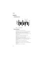
The lightning flash with the arrowhead symbol,
within an equilateral triangle is intended to alert
the user to the presence of uninsulated
"dangerous voltage" within the product's
enclosure that may be of sufficient magnitude
to constitute a risk of electric shock to persons.
CAUTION
RISK OF ELECTRIC SHOCK
DO NOT OPEN
CAUTION: TO REDUCE THE RISK OF ELECTRIC SHOCK,
DO NOT REMOVE THE COVER
NO USER SERVICEABLE PARTS INSIDE
REFER SERVICING TO QUALIFIED SERVICE PERSONNEL
The exclamation point within an equilateral
triangle is intended to alert the user to the
presence of important operating and
maintenance (servicing) instructions in the
literature accompanying the product.
IMPORTANT SAFETY & INSTALLATION INSTRUCTIONS
INSTRUCTIONS PERTAINING TO THE RISK OF FIRE, ELECTRIC SHOCK, OR INJURY TO PERSONS
WARNING: When using electric products, basic precautions should
always be followed, including the following:
1.
Read all of the Safety and Installation Instructions and Explanation
of Graphic Symbols before using the product.
2.
Do not use this product near water—for example, near a bathtub,
washbowl, kitchen sink, in a wet basement, or near a swimming
pool, or the like.
3.
This product should be used only with a stand or cart that is
recommended by the manufacturer.
4.
This product, either alone or in combination with an amplifier and
speakers or headphones, may be capable of producing sound
levels that could cause permanent hearing loss. Do not operate for
a long period of time at a high volume level or at a level that is
uncomfortable. If you experience any hearing loss or ringing in the
ears, you should consult an audiologist.
5.
The product should be located so that its location or position does
not interfere with its proper ventilation.
6.
The product should be located away from heat sources such as
radiators, heat registers, or other products that produce heat.
7.
The product should be connected to a power supply only of the type
described in the operating instructions or as marked on the product.
8.
This product may be equipped with a polarized line plug (one blade
wider than the other). This is a safety feature. If you are unable to
insert the plug into the outlet, contact an electrician to replace your
obsolete outlet. Do not defeat the safety purpose of the plug.
9.
The power supply cord of the product should be unplugged from the
outlet when left unused for a long period of time. When unplugging
the power supply cord, do not pull on the cord, but grasp it by the
plug.
10. Care should be taken so that objects do not fall and liquids are not
spilled into the enclosure through openings.
11. The product should be serviced by qualified service personnel
when:
A.
The power supply cord or the plug has been damaged;
B.
Objects have fallen onto, or liquid has been spilled into the
product;
C.
The product has been exposed to rain;
D.
The product does not appear to be operating normally or
exhibits a marked change in performance;
E.
The product has been dropped, or the enclosure damaged.
12. Do not attempt to service the product beyond that described in the
user maintenance instructions. All other servicing should be
referred to qualified service personnel.
13. WARNING: Do not place objects on the product’s power supply
cord, or place the product in a position where anyone could trip
over, walk on, or roll anything over cords of any type. Do not allow
the product to rest on or be installed over cords of any type.
Improper installations of this type create the possibility of a fire
hazard and/or personal injury.
RADIO AND TELEVISION INTERFERENCE
WARNING: Changes or modifications to this instrument not expressly
approved by Young Chang could void your authority to operate the
instrument.
IMPORTANT: When connecting this product to accessories and/or other
equipment use only high quality shielded cables.
NOTE: This instrument has been tested and found to comply with the
limits for a Class A digital device, pursuant to Part 15 of the FCC Rules.
These limits are designed to provide reasonable protection against
harmful interference when the instrument is used in a commercial
environment. This instrument generates, uses, and can radiate radio
frequency energy and, if not installed and used in accordance with the
instruction manual, may cause harmful interference to radio
communications. Operation of this instrument in a residential area is
likely to cause harmful interference, in which case the user will be
required to correct the interference at his or her own expense.
Changes and modifications not expressly approved by the manufacturer
or registrant of this instrument can void the user’s authority to operate
this instrument under Federal Communications Commission rules.
In order to maintain compliance with FCC regulations, shielded cables
must be used with this instrument. Operation with unapproved
equipment or unshielded cables is likely to result in harmful interference
to radio and television reception.
NOTICE
This apparatus does not exceed the Class A limits for radio noise
emissions from digital apparatus set out in the Radio Interference
Regulations of the Canadian Department of Communications.
AVIS
Le present appareil numerique n’emet pas de bruits radioelectriques
depassant les limites applicables aux appareils numeriques de la
class A prescrites dans le Reglement sur le brouillage radioelectrique
edicte par le ministere des Communications du Canada.
SAVE THESE INSTRUCTIONS
ii
Young Chang Distributors
Contact the nearest Young Chang office listed below to locate your local Young Chang/Kurzweil
representative.
A N D Music Corp.
P.O. Box 99995
Lakewood, WA 98499-0995
Tel: (253) 589-3200
Fax: (253) 984-0245
Young Chang Akki Co., Ltd.
178-55 Gajwa-Dong
Seo-Ku, Inchon
Korea 404-250
Tel: 011-82-32-570-1380
Fax: 011-82-32-570-1218
Young Chang America, Inc. (Canadian Division)
P.O. Box 61515
9350 Yonge Street
Richmond Hill, Ontario
Canada L4C 3N0
Tel: (905) 508-0531
Fax: (905) 508 1308
iii
Contents
Young Chang Distributors ............................................................................................................................................... iii
Chapter 1
Introduction
Models ....................................................................................................................................................................... 1-1
Notes, Cautions, Warnings ..................................................................................................................................... 1-1
PC2/PC2X ........................................................................................................................................................................ 1-2
PC2/PC2X Rear Panel ............................................................................................................................................. 1-2
Rear Panel Features.................................................................................................................................................. 1-2
PC2/PC2X Front Panel............................................................................................................................................ 1-3
Front Panel Features ................................................................................................................................................ 1-3
PC2R.................................................................................................................................................................................. 1-6
PC2R Rear Panel....................................................................................................................................................... 1-6
Rear Panel Features.................................................................................................................................................. 1-6
PC2R Front Panel ..................................................................................................................................................... 1-6
Front Panel Features ................................................................................................................................................ 1-7
Chapter 2
Diagnostics
Diagnostic Tests ............................................................................................................................................................... 2-1
Entering Diagnostics....................................................................................................................................................... 2-2
Diagnostic Test Modes.................................................................................................................................................... 2-2
Run One Test............................................................................................................................................................. 2-2
Run Burn-in............................................................................................................................................................... 2-3
Test Results....................................................................................................................................................................... 2-3
Description of Tests......................................................................................................................................................... 2-4
ROM ........................................................................................................................................................................... 2-4
Read-write................................................................................................................................................................. 2-4
RAM ........................................................................................................................................................................... 2-4
MABEL ...................................................................................................................................................................... 2-4
LISA ........................................................................................................................................................................... 2-4
Sound ROM .............................................................................................................................................................. 2-4
ZRAM ........................................................................................................................................................................ 2-5
MIDI ........................................................................................................................................................................... 2-5
LED............................................................................................................................................................................. 2-5
PCX-1 ROM............................................................................................................................................................... 2-5
PCX-1 RW.................................................................................................................................................................. 2-5
PCX-1 RAM............................................................................................................................................................... 2-5
PCX-1 MABEL .......................................................................................................................................................... 2-6
PCX-1 SROM............................................................................................................................................................. 2-6
Chapter 3
PC2R Disassembly/Assembly
Introduction ..................................................................................................................................................................... 3-1
Cables, Connectors................................................................................................................................................... 3-1
Flat Ribbon Cables ............................................................................................................................................ 3-1
Cable Routing.................................................................................................................................................... 3-1
Required Tools and Materials................................................................................................................................. 3-1
Opening the PC2R........................................................................................................................................................... 3-2
Kurzweil PC2 Series Service Manual
Contents
Removing the Top Cover ........................................................................................................................................ 3-2
Replacing the Top Cover......................................................................................................................................... 3-2
Removing the Connector Board............................................................................................................................. 3-3
Replacing the Connector Board ............................................................................................................................. 3-4
Removing the Polyphony Expansion Board (PCX-1) ......................................................................................... 3-5
Replacing the Polyphony Expansion Board (PCX-1).......................................................................................... 3-5
Removing the Engine Board................................................................................................................................... 3-6
Replacing the Engine Board ................................................................................................................................... 3-6
Front Panel Assembly ..................................................................................................................................................... 3-8
Removing the Front Panel Assembly .................................................................................................................... 3-8
Replacing the Front Panel Assembly..................................................................................................................... 3-8
Removing the Front Panel Faceplate..................................................................................................................... 3-9
Replacing the Front Panel Faceplate ..................................................................................................................... 3-9
Front Panel Boards................................................................................................................................................... 3-9
Removing the Right Front Panel Board .............................................................................................................. 3-10
Replacing the Right Front Panel Board................................................................................................................3-11
Removing the LCD Board......................................................................................................................................3-11
Replacing the LCD Board ..................................................................................................................................... 3-12
Removing the Left Front Panel Board................................................................................................................. 3-12
Replacing the Left Front Panel Board ................................................................................................................. 3-13
Removing the Headphone/Volume/Power Switch Board ............................................................................. 3-14
Replacing the Headphone/Volume/Power Switch Board .............................................................................. 3-14
Chapter 4
PC2/PC2X Disassembly/Assembly
Introduction ..................................................................................................................................................................... 4-1
Notes, Cautions, Warnings ..................................................................................................................................... 4-1
Cables, Connectors................................................................................................................................................... 4-1
Flat Ribbon Cables ............................................................................................................................................ 4-1
Cable Routing.................................................................................................................................................... 4-1
Required Tools and Materials................................................................................................................................. 4-1
Opening the PC2/PC2X ................................................................................................................................................. 4-2
PC2 Bottom ............................................................................................................................................................... 4-2
PC2X Bottom............................................................................................................................................................. 4-3
Removing the Top Enclosure.................................................................................................................................. 4-4
Replacing the Top Enclosure .................................................................................................................................. 4-6
Closing the PC2/PC2X............................................................................................................................................ 4-6
Top Enclosure................................................................................................................................................................... 4-7
Removing the Enclosure Support Walls ............................................................................................................... 4-8
Left Enclosure Support Wall............................................................................................................................ 4-8
Right Enclosure Support Wall......................................................................................................................... 4-8
Replacing the Enclosure Support Walls................................................................................................................ 4-8
Left Enclosure Support Wall............................................................................................................................ 4-8
Right Enclosure Support Wall......................................................................................................................... 4-8
Removing the Connector Board............................................................................................................................. 4-8
Replacing the Connector Board ........................................................................................................................... 4-10
Removing the Front Panel Board......................................................................................................................... 4-10
Replacing the Front Panel Board ......................................................................................................................... 4-12
Removing the LCD Board..................................................................................................................................... 4-13
Replacing the LCD Board ..................................................................................................................................... 4-13
Removing the Polyphony Expansion Board (PCX-1) ....................................................................................... 4-13
Replacing the Polyphony Expansion Board (PCX-1)........................................................................................ 4-14
ii
Kurzweil PC2 Series Service Manual
Contents
Removing the Slider Board................................................................................................................................... 4-14
Replacing the Slider Board ................................................................................................................................... 4-15
Removing the Engine Board................................................................................................................................. 4-15
Replacing the Engine Board ................................................................................................................................. 4-17
Removing the Mod Wheel Assembly.................................................................................................................. 4-17
Replacing the Mod Wheel Assembly .................................................................................................................. 4-18
PC2 Keyboard Assembly.............................................................................................................................................. 4-19
Removing the PC2 Keyboard Assembly............................................................................................................. 4-19
Replacing the PC2 Keyboard Assembly ............................................................................................................. 4-20
Disconnecting the PC2 Keyboard ........................................................................................................................ 4-21
Connecting the Keyboard ..................................................................................................................................... 4-21
Removing Keys ...................................................................................................................................................... 4-22
Natural/White Key ........................................................................................................................................ 4-22
Natural/White Keys.............................................................................................................................................. 4-23
Sharp/Black Keys .................................................................................................................................................. 4-23
Replacing a Key...................................................................................................................................................... 4-24
Servicing the Keyboard Contact Boards ............................................................................................................. 4-24
Removing the Treble Contact Board ............................................................................................................ 4-24
Replacing the Treble Contact Board ............................................................................................................. 4-24
Removing the Bass Contact Board ............................................................................................................... 4-24
Replacing the Bass Contact Board ................................................................................................................ 4-24
Removing the Keyboard Contact Strips ............................................................................................................. 4-25
Replacing the Keyboard Contact Strips .............................................................................................................. 4-25
PC2X Keyboard Assembly ........................................................................................................................................... 4-26
Removing the PC2X Keyboard Assembly .......................................................................................................... 4-26
Replacing the PC2X Keyboard Assembly........................................................................................................... 4-27
Removing Keys ...................................................................................................................................................... 4-27
Natural/White Key ........................................................................................................................................ 4-28
Natural/White Keys.............................................................................................................................................. 4-28
Sharp/Black Keys .................................................................................................................................................. 4-29
Replacing a Key...................................................................................................................................................... 4-30
Servicing the Keyboard Contact Boards ............................................................................................................. 4-30
Removing the Treble Contact Board ............................................................................................................ 4-30
Replacing the Treble Contact Board ............................................................................................................. 4-30
Removing the Bass Contact Board ............................................................................................................... 4-30
Replacing the Bass Contact Board ................................................................................................................ 4-31
Removing the Keyboard Contact Strips ............................................................................................................. 4-31
Replacing the Keyboard Contact Strips .............................................................................................................. 4-32
Removing a Key Weight........................................................................................................................................ 4-32
Replacing a Key Weight ........................................................................................................................................ 4-33
Chapter 5
Troubleshooting
Introduction ..................................................................................................................................................................... 5-1
Cables, Connectors................................................................................................................................................... 5-1
Flat Ribbon Cables ............................................................................................................................................ 5-1
Cable Routing.................................................................................................................................................... 5-1
Surface-Mount Devices ........................................................................................................................................... 5-1
Saving User Data...................................................................................................................................................... 5-1
Boot Block......................................................................................................................................................................... 5-2
Entering the Boot Block........................................................................................................................................... 5-2
Resets................................................................................................................................................................................. 5-2
iii
Kurzweil PC2 Series Service Manual
Contents
Hard Reset................................................................................................................................................................. 5-2
Soft Reset ................................................................................................................................................................... 5-2
Software Updates ............................................................................................................................................................ 5-3
File Formats............................................................................................................................................................... 5-3
Installing the Operating System or Setups........................................................................................................... 5-3
Installing a New Boot Block ................................................................................................................................... 5-4
Installing Sound ROM Options.............................................................................................................................. 5-4
Replacing the Battery...................................................................................................................................................... 5-5
PC2 Keyboard Models............................................................................................................................................. 5-5
Accessing the Battery ....................................................................................................................................... 5-5
Removing the Battery....................................................................................................................................... 5-5
Installing the Battery ........................................................................................................................................ 5-5
PC2R Rack Models................................................................................................................................................... 5-6
Accessing the Battery ....................................................................................................................................... 5-6
Removing the Battery....................................................................................................................................... 5-6
Installing the Battery ........................................................................................................................................ 5-6
Scanner Tests .................................................................................................................................................................... 5-7
PC2R Rack Models................................................................................................................................................... 5-7
Front Panel Buttons .......................................................................................................................................... 5-7
Alpha Wheel ...................................................................................................................................................... 5-7
Front Panel Knobs............................................................................................................................................. 5-7
PC2 Keyboard Models............................................................................................................................................. 5-8
Front Panel Buttons .......................................................................................................................................... 5-8
Alpha Wheel ...................................................................................................................................................... 5-8
Front Panel Sliders............................................................................................................................................ 5-8
Wheels ................................................................................................................................................................ 5-9
Keyboard ............................................................................................................................................................ 5-9
Switch Pedals 1, 2, and 3.................................................................................................................................. 5-9
Continuous Pedals 1 and 2 .............................................................................................................................. 5-9
Power Problems............................................................................................................................................................. 5-10
Dead ......................................................................................................................................................................... 5-10
Audio Problems............................................................................................................................................................. 5-10
No Audio................................................................................................................................................................. 5-10
Front Panel Problems.....................................................................................................................................................5-11
LCD not lit................................................................................................................................................................5-11
Buttons, Sliders or Controllers not working .......................................................................................................5-11
Keyboard Problems....................................................................................................................................................... 5-12
Dead Keyboard....................................................................................................................................................... 5-12
Dead Note(s) ........................................................................................................................................................... 5-12
One or More in a Section................................................................................................................................ 5-12
Mechanical Noise............................................................................................................................................ 5-12
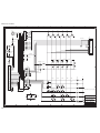
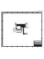
PC2R Interconnect Diagram ........................................................................................................................................ 5-13
PC2 Interconnect Diagram........................................................................................................................................... 5-14
Chapter 6
Parts Lists
Introduction ..................................................................................................................................................................... 6-1
PC2/PC2X Printed Circuit Boards and Assemblies............................................................................................ 6-1
PC2R Printed Circuit Boards and Assemblies ..................................................................................................... 6-2
PC2R/PC2/PC2X............................................................................................................................................................ 6-3
Engine Board, N012300051 ..................................................................................................................................... 6-3
PC2/PC2X ........................................................................................................................................................................ 6-5
iv
Kurzweil PC2 Series Service Manual
Contents
Front Panel Board, N012400052 ............................................................................................................................. 6-5
Connector Board, N012300061 ............................................................................................................................... 6-6
LCD Board, N012103800 ......................................................................................................................................... 6-8
Pitch & Mod Wheel Assembly, N012300053 ........................................................................................................ 6-8
Slider Board, N012400051 ....................................................................................................................................... 6-9
PC2 .................................................................................................................................................................................... 6-9
Final Assembly, N012000150 .................................................................................................................................. 6-9
Keyboard Assembly, N215040311 ........................................................................................................................ 6-10
PC2X.................................................................................................................................................................................6-11
Final Assembly N012000151 ..................................................................................................................................6-11
Keyboard Assembly, N215040413........................................................................................................................ 6-12
PC2R................................................................................................................................................................................ 6-13
Connector Board, N01230004 ............................................................................................................................... 6-13
Front Panel Assembly, N012300070..................................................................................................................... 6-14
Left Front Panel Board, N012300080 ................................................................................................................... 6-14
Right Front Panel Board, N012300090................................................................................................................. 6-15
Headphone/Volume/Power Switch Board, N012700019................................................................................ 6-15
LCD Board, N012103802 ....................................................................................................................................... 6-15
Final Assembly, N012000153 ................................................................................................................................ 6-16
Chapter 7
Schematics
Engine Board–Microprocessor (page 1 of 5)................................................................................................................ 7-3
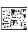
Engine Board–Master/Slave Mabels (page 2 of 5) ..................................................................................................... 7-4
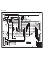
Engine Board–Lisa F/X 128Ch Option, Clocks (page 3 of 5).................................................................................... 7-5
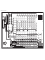
Engine Board–Sound ROM, Uart, Glue, Decoupling (page 4 of 5).......................................................................... 7-6
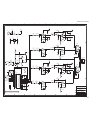
Engine Board–Audio Channel, Muting Control (page 5 of 5) .................................................................................. 7-7
Front Panel and IBBB Board (keyboard models)–FP Buttons and LEDs (page 1 of 2).......................................... 7-8
Front Panel and IBBB Board (keyboard models)–IBBB Buttons and LEDs (page 2 of 2) ..................................... 7-9
Connector Board (keyboard models)–Scanner (page 1 of 3)................................................................................... 7-10
Connector Board (keyboard models)–Digital Interface (page 2 of 3) .....................................................................7-11
Connector Board (keyboard models)–Power Supply/Audio (page 3 of 3).......................................................... 7-12
Slider Board (keyboard models)–Sliders ................................................................................................................... 7-13
Right Front Panel Board (rack models)–FP Buttons and LEDs (page 1 of 2) ....................................................... 7-14
Left Front Panel Board (rack models)–Controllers, FP Buttons and LEDs (page 2 of 2) .................................... 7-15
Connector Board (rack models)–Scanner (page 1 of 3)............................................................................................ 7-16
Connector Board (rack models)–Digital Interface (page 2 of 3) ............................................................................. 7-17
Connector Board (rack models)–Power Supply/Audio (page 3 of 3) ................................................................... 7-18
Power/Volume/Headphone Board (rack models) .................................................................................................. 7-19
v
Kurzweil PC2 Series Service Manual
Contents
vi
Chapter 1
Introduction
This chapter provides the service technician with a layout of the front and rear panel features, as
well as a brief explanation of thier functions. For in-depth descriptions of the many features the
PC2 Series instruments include, consult the Musician’s Guide.
This chapter also includes a description of the models available in the PC2 Series and a
description of the symbols used throughout this manual.
Note: If possible, all user programs and setups should be saved prior to opening the unit,
entering the Boot Block to run diagnostics or to perform a hard reset. For instructions to save all
user programs and setups, see Saving User Data in Chapter 5, page 5-1.
Models
There are three models in the PC2 series. The available models are listed below.
•
•
•
PC2, 76-note keyboard
PC2X, 88-note keyboard
PC2R, rack-mount
Notes, Cautions, Warnings
Please pay special attention to all Notes, Cautions, and Warnings used throughout this manual
as they not only point out specific instructions, but also alert you to differences between the
PC2R rack units, the 76-note PC2 keyboard, and the 88-note PC2X keyboard. Certain chapters
and sections are solely for the rack or keyboard units. Other chapters combine both the rack and
keyboard units.
A brief description of these symbols follows:
Note: Provides additional information, indicates differences between models, and emphasizes
specific instructions.
Caution: Instructs you to proceed cautiously so that damage does not occur to the unit or
individual components.
Warning: Alerts you so that damage does not occur to yourself, others, or external devices.
1-1
Introduction
PC2/PC2X
PC2/PC2X
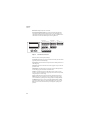
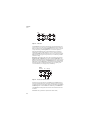
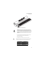
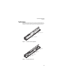
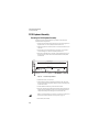
PC2/PC2X Rear Panel
Power
Connector
Power
I / 0
Digital
Out
MIDI
Adapter In
Thru / Out
Breath
Input
Ribbon
Input
Pedals
In
Thru / Out
Out
LCD
Contrast
Digital
Out
Switch
1
Inputs
2
3
Continuous
1
Breath
Audio Outs
Ribbon
2
Left
Right
Headphones
9.0V 2.0A
14.0V~0.25A
MIDI
Ports
Power
Switch
MIDI
Select Switch
Figure 1-1
Switch
Pedals
LCD
Contrast
Audio
Outs
Continuous
Control
Pedals
Headphones
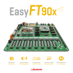
PC2 rear panel features
Rear Panel Features
Power Switch—Rocker switch to turn the power on and off.
Power Connector—Keyed four-pin connector to attach the Kurzweil 9VDC power adapter.
MIDI Select Switch—Slide switch to select the operation of the MIDI Thru/Out port. This
switch is recessed into the rear panel so that it cannot be accidentally changed.
MIDI Ports—In, Thru/Out, and Out ports to connect the PC2 to other MIDI devices to receive,
pass, and send MIDI data.
LCD Contrast—Rotary potentiometer to adjust the LCD for the best visibility.
Digital Out—RCA jack to connect to digital recorders and mixers.
Switch Pedals—Three 1/4” jacks to connect switch pedals that can be assigned to control
operations such as sustain, sostenuto, etc. (use 1/4” tip/sleeve).
Continuous Control Pedals—Two 1/4” jacks to connect pedals that can be assigned to control
operations such as volume, expression, etc. (use 10KΩ linear taper potentiometer, 1/4”
tip/ring/sleeve).
Breath Input—A 3.5mm jack to connect a standard breath controller.
Ribbon Input—Modular jack to connect the Kurzweil Ribbon Controller option.
Audio Outs—Balanced 1/4” left and right audio output jacks to connect to an amplifier, mixer
or sound system.
Headphones—Standard 1/4” jack to connect headphones.
1-2
Introduction
PC2/PC2X
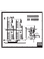
PC2/PC2X Front Panel
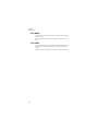
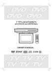
Figure 1-2 is an illustration of the front panel for the PC2 and the PC2X. Enlargements of
sections of this illustration follow, as well as a brief description of the front panel features.
Zone
Parameters
LCD and
cursor buttons
Zone Parameters
Zone Select and Assignable Controllers
MIDI Xmit
Main
Layer
Zone 1
Split
Zone 2
Perc On / Off
Zone 3
Volume
A
Zone 4
Decay
B
C
System
Sound Parameters
Program Key Range Transpose
Timbre
Envelope
System
LFO
Alpha Wheel,
Minus (-) and Plus (+) buttons,
Alphanumeric keypad
Data Entry
Global
MIDI Recv
Panic
Split Layer
Pitch
Split Point
Master
Volume
Sound
Parameters
Solo
Functions
Drawbar
Toggle
Velocity
Controllers Arpeggiator
Compare
Copy
Store
D
1
2
3
ABC
DEF
GHI
4
5
6
JKL
MNO
PQR
7
8
9
STU
VWX
+/-
0
EQ
Sound Source
Internal
User
Exp 1
Exp 2
Octave Shift
SW1
Sound / Setup Select
Internal
Voices
Rotary
Fast / Slow
MIDI
Setups
Effects and Reverb
KB3
Mode
Piano 1
SW2
L
o
w
H
i
g
h
M
i
d
16'
2 2/3'
5 1/3'
2'
Chorus / Vib
On / Off
Previous
Group
Next
Group
4'
1 1/3'
E Piano 1 E Piano 2 Pop Keys
Clavier
Organ
Brass
2
3
4
5
6
7
8
Voices
Synths
Pads
Guitar
Bass
Drums
Percussion
9
10
11
12
13
14
15
16
Chorus / Vib
Depth
Select
FX-B
Select
Wet / Dry
FX Mode
YZ
Clear
Space
Cancel
Enter
No
Yes
Mute B
Demo
Effects
and
Reverb
Sound/Setup
Select
Master
Volume
Figure 1-2
FX-A
Mute A
SW3
8'
1 3/5'
Piano 2
1
Strings
UPPER / lower 0 - 9
Sound
Source
Sound/Setup
Select
PC2/PC2X Front Panel layout
Front Panel Features
Zone Select and Assignable Controllers
Main
Layer
Zone 1
Split
Zone 2
Perc On / Off
Zone 3
Volume
Split Layer
Zone 4
Decay
Pitch
Split Point
Master
Volume
A
B
C
Solo
Drawbar
Toggle
D
EQ
Octave Shift
SW1
Rotary
Fast / Slow
SW2
L
o
w
M
i
d
16'
2 2/3'
Figure 1-3
H
i
g
h
5 1/3'
2'
Chorus / Vib
On / Off
SW3
8'
1 3/5'
4'
1 1/3'
Chorus / Vib
Depth
Master Volume, Zone Select and Assignable Controllers section
1-3
Introduction
PC2/PC2X
Master Volume—Slidepot to adjust the overall volume.
Zone Select and Assignable Controllers—The operation of the buttons and sliders in this
section depends on which of the three performance modes is active. Their labelling is colorcoded to identify their function in each of the performance modes. They are labelled as follows:
white–Internal Voices mode, blue–MIDI Setups mode, and orange–KB3 mode.
Zone Parameters
MIDI Xmit
Sound Parameters
Program Key Range Transpose
Timbre
Envelope
System
LFO
Global
MIDI Recv
Panic
Functions
Velocity
Controllers Arpeggiator
Compare
Copy
Store
Sound Source
Internal
Figure 1-4
User
Exp 1
Exp 2
PC2 Front Panel, center section
LCD—Forty-character, two-line liquid crystal display.
Cursor buttons—These buttons move the cursor bar in the LCD. Generally, they select bank and
program ID parameters and some KB3 settings.
Zone Parameters—Each button in this section represents a menu of available parameters for use
while editing setups.
Sound Source—Each button in this section selects a bank of programs or setups for each of the
performance modes.
Sound Parameters—Each button in this section represents a menu of available parameters for
use while editing programs in the Internal Voices and KB3 modes.
Functions—Use the buttons in this section while editing programs or settings to compare
between an original and a modified setup or program, copy sections from one setup to another,
and begin the process to store the changes.
System—The three buttons in this section select parameters that affect the entire unit. The
Global button opens a menu of parameters such as: checking the version of the operating
system, available memory, performing a reset, dumping all objects, and running MIDIScope.
The MIDI Receive button opens a menu to configure individual MIDI channels. The Panic
button sends an All Notes Off message to the PC2 and the MIDI Out port. On power up, the
Panic button is also used to enter the boot block to perform diagnostics, operating system
updates, etc.
1-4
Introduction
PC2/PC2X
Sound / Setup Select
Internal
Voices
Previous
Group
MIDI
Setups
Effects and Reverb
KB3
Mode
Next
Group
Piano 1
Piano 2
Clavier
Organ
Brass
1
2
3
4
5
6
7
8
Strings
Voices
Synths
Pads
Guitar
Bass
Drums
Percussion
9
10
11
12
13
14
15
16
E Piano 1 E Piano 2 Pop Keys
FX-A
Select
Wet / Dry
Mute A
FX-B
Select
FX Mode
Mute B
Demo
Figure 1-5
Sound/Setup Select and Effects and Reverb sections
Sound/Setup Select—Three groups of buttons are included in this section. Use the buttons in
the first group to select one of the three performance modes: Internal Voices, MIDI Setups, or
KB3 Mode. The second group, Previous Group and Next Group, is for use in the Internal Voices
and MIDI Setups modes only. Depending on which mode you’re in, they select the previous or
next group of programs or setups. Use the buttons in the third group, labelled 1–16, to select a
category of Internal Voice programs or MIDI setups. In KB3 Mode, use these buttons to select
one of the 16 KB3 programs.
Effects and Reverb—Use the buttons in this section to select from two blocks of effects to apply
effects and reverb to programs and setups.
Data Entry
1
2
3
ABC
DEF
GHI
4
5
6
JKL
MNO
PQR
7
8
9
STU
VWX
YZ
+/-
0
Clear
UPPER / lower 0 - 9
Figure 1-6
Space
Cancel
Enter
No
Yes
Data Entry section
Data Entry—This section contains the Alpha Wheel, Minus (-) and Plus (+) buttons, and the
Alphanumeric keypad. Use the Alpha Wheel or the Minus (-) and Plus (+) buttons to increase or
decrease a value. Use the buttons in the Alphanumeric keypad to enter text, numbers, spaces,
etc. This section also includes the Cancel (No) and Enter (Yes) buttons.
Mod/Pitch Wheel Assembly (not shown)—Use the two wheels to vary modulation and pitch.
Also included on the assembly is the SW4 and SW5 switches for use in the Internal Voices and
MIDI Setups modes.
1-5
Introduction
PC2R
PC2R
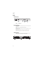
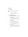
PC2R Rear Panel
L
®
R
Serial No.
Audio Outs
Model: PC2R
Manufacturer: Young Chang Co., Ltd.
Designed in USA
Made in R.O.K.
PC2R
Audio
Outs
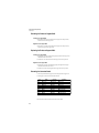
Figure 1-7
In
Thru
Out
Power In
Digital Out
THIS DEVICE COMPLIES WITH PART 15
OF THE FCC RULES. OPERATION IS
SUBJECT TO THE FOLLOWING TWO
CONDITIONS:
(1) THIS DEVICE MAY NOT CAUSE
HARMFUL INTERFERENCE
(2) THIS DEVICE MUST ACCEPT ANY
INTERFERENCE RECEIVED, INCLUDING
Thru / Out
MIDI
9.0V 2.0A
14.0V~0.25A
MIDI
Select Switch
Digital
Out
MIDI
Ports
Power
In
PC2R rear panel
Rear Panel Features
Audio Outs—Balanced 1/4” left and right audio output jacks to connect to an amplifier, mixer
or sound system.
Digital Out—RCA jack to connect to digital recorders and mixers.
MIDI Ports—In, Thru/Out, and Out ports to connect the PC2 to other MIDI devices to receive,
pass, and send MIDI data.
MIDI Select Switch—Slide switch to select the operation of the MIDI Thru/Out port.
Power In—Keyed four-pin connector to attach the Kurzweil 9VDC power adapter.
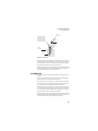
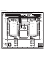
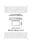
PC2R Front Panel
Figure 1-8 is an illustration of the front panel for the PC2R. Enlargements of sections of this
illustration follow, as well as a brief description of the front panel features.
Power/
Volume
PUSHPWR
VOL
Performance
Performance
Zone 1
Zone 2
Main
Solo
Rotary Fast / Slow Perc On / Off
Shift
A
Drawbar Toggle
Zone 3
Split
Split Layer
Volume
Decay
Pitch
C
8'
4'
2'
1 3/5'
1 1/3'
Chorus / Vib
On / Off
Chorus / Vib
Depth
Headphones
LCD
Figure 1-8
1-6
D
5 1/3'
2 2/3'
Pre-Amp
Edit
Edit / Store
Modes
Group / Menu
Compare
Copy
Internal Voices
KB3
MIDI Setups
Panic
16'
1'
PC2R
Zone 4
Layer
B
Modes
Edit
PC2R Front Panel
Cancel
Enter
No
Yes
FX
MIDI Receive
Global
Demo
LCD
Contrast
Introduction
PC2R
Front Panel Features
Power/Volume—Push to turn the power on/off and turn it to adjust the volume.
Headphones—Standard 1/4” jack to connect headphones.
Performance section—The buttons and knobs in this section are multi-function and their
operation depends on which performance mode is active (Internal Voices, KB3, or MIDI Setups).
Their labelling is color-coded to identify their operation for each of the performance modes.
They are labelled as follows: white–Internal Voices mode, blue–MIDI Setups mode, and
orange–KB3 mode.
PUSHPWR
VOL
Performance
Zone 1
Drawbar Toggle
Figure 1-9
Zone 3
Layer
Rotary Fast / Slow Perc On / Off
Shift
Zone 2
Main
Solo
A
Split
Volume
Zone 4
Split Layer
Decay
B
Pitch
C
D
16'
5 1/3'
8'
4'
2 2/3'
2'
1 3/5'
1 1/3'
Chorus / Vib
On / Off
Chorus / Vib
Depth
1'
Pre-Amp
Power/Volume, Headphones and Performance section
The top row of buttons are for use in each of the three performance modes. The button LEDs are
tri-colored: Red, Green, and Amber. The function of a button depends on which performance
mode is active and the LED color. In the Internal Voices mode, use these buttons to enter
AutoSplit mode to add layers and splits. In MIDI Setups mode, use these buttons to solo a zone
or select a zone for viewing or editing. In KB3 mode, these buttons control the effects for the
current KB3 program. Figure 1-9 is an enlargement of the Performance section. An example of
the operation of the Split button in each performance mode follows:
Internal Voices mode, selecting the Split button switches to AutoSplit mode and adds a
new sound below a preset split point.
MIDI Setups mode (Zone 3), selecting the Split button selects Zone 3.
KB3 mode (Decay), selecting the Split button switches between fast and slow decay for
the percussion effect.
The bottom row includes the Shift button and Knobs A–D. The Shift button controls the
operation of Knobs A–D. The Shift button LED is also tri-colored (green, amber, and red). The
function of Knobs A–D depends on which performance mode is active and the LED color. In
Internal Voices or MIDI Setups mode, Knobs A–D control parameters and settings. In KB3
Mode, Knobs A–D control such functions as drawbar lengths, etc.
Edit section—Use the eight buttons and the Alpha Wheel in this section to select programs and
setups, and editing functions. Turn the Alpha Wheel to scroll through menus and categories to
select a program or parameter. In Internal Voices and KB3 mode, use the Left and Right cursor
buttons to select bank and program ID parameters, as well as some KB3 settings. While editing
use these buttons to make selections.
1-7
Introduction
PC2R
Edit
Edit / Store
Figure 1-10
Group / Menu
Compare
Copy
Cancel
Enter
No
Yes
Edit section
Select the Edit/Store button to enter the edit mode for the current performance mode to edit
programs, setups, etc. To save the changes, press the Edit/Store button again to enter the save
dialog. In a performance mode, press the Group/Menu button to select a category of programs
or setups. In edit mode, press the Group/Menu button to view the menu of parameters.
When editing, the Compare button lets you hear the difference between an original and a
modified setup or program. The Copy button allows you to copy sections from one setup to
another. The Cancel (No) button exits an edit mode or answers no. In a performance mode, the
Enter (Yes) button selects a program or setup and answers yes. In an edit mode, press Enter to
enter menus for editing.
Modes section—Use the buttons in this section to select one of the three performance modes:
Internal Voices, KB3, or MIDI Setups. Three special mode buttons (FX, MIDI Receive, and
Global) are also included in this section. The special mode buttons perform as follows: press the
FX button to enter the effect edit mode, press the MIDI Receive button to configure individual
MIDI channels, and press the Global button to select parameters that change the entire PC2R.
Many helpful parameters are included in the Global menu such as: the operating system
version, available memory, reset, dumping all objects, and MIDIScope.
Modes
Internal Voices
KB3
MIDI Setups
FX
MIDI Receive
Panic
Global
Demo
Figure 1-11
Modes section and LCD Contrast
The Modes section also contains buttons to select the Panic function and Demo mode. These
buttons are not individual buttons. They are selected by simultaneously pressing two buttons.
To select the Panic function to send an All Notes Off message, simultaneously press the KB3 and
the MIDI Setups buttons. To enter the Demo mode, simultaneously press the MIDI Receive
and the Global buttons. Flashing LEDs in the Performance section indicate the location of the
stored demos.
LCD Contrast—Rotary potentiometer to adjust the LCD for the best visibility.
1-8
Chapter 2
Diagnostics
Diagnostic Tests
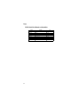
The following lists the diagnostic tests available for the PC2 Series.
•
•
•
•
•
•
•
•
•
ROM
Read-write
RAM
MABEL
LISA
Sound ROM
ZRAM
MIDI
LED
If a PCX-1 Board is installed, the following tests are also available:
•
•
•
•
•
PCX-1 ROM
PCX-1 RW
PCX-1 RAM
PCX-1 MABEL
PCX-1 SROM
Warning: Some diagnostic tests erase user programs and setups. If possible, be sure to save all
user programs and setups, before entering diagnostics. For instructions, refer to Saving User Data
in Chapter 5, page 5-1.
2-1
Diagnostics
Entering Diagnostics
Entering Diagnostics
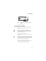
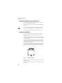
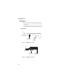
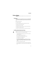
1. Apply power to the unit. When the Please wait... message appears in the LCD,
quickly press and release the Panic button for PC2 keyboard units or the Edit button for
PC2R rack units. The LCD should display the following:
Main menu
Install engine
Figure 2-1
LCD example, entering diagnostics
2. Press either the Left or Right cursor button until Run
diagnostics appears in the LCD.
3. Press the Enter button.
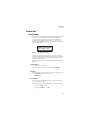
4. The LCD displays the following:
Main menu
Run one test
Figure 2-2
LCD example, diagnostic main menu
5. Press Enter to select the run one test mode. To select the run burn-in test mode, press
either the Left or Right cursor button then press the Enter button to begin the tests.
Diagnostic Test Modes
Run One Test
Run One Test allows you to select an individual test, or to step through and run each available
test. To step through the different tests, use the Left or Right cursor button. Press the Enter
button to select the test.
Select test to run
ROM test
Figure 2-3
2-2
LCD example, Run One Test
Diagnostics
Test Results
At the completion of a test, whether pass or fail, press the Cancel button to exit the test. Press
either the Left of Right cursor button to advance to the next test or another test in the sequence.
At the completion of a test, press the Cancel button to return to the test menu. To exit
diagnostics, turn the power off and on to return to normal operation.
Run Burn-in
Burn-in continuously runs the following sequence of tests.
•
•
•
•
•
ROM
Read-write
Sound ROM
ZRAM
MIDI
If a PCX-1 Board is installed, the sequence of tests is as follows:
•
•
•
•
•
ROM
Read-write
MIDI
PCX-1 ROM
PCX-1 read
The LCD displays the test results at the completion of each test. To stop the burn-in process and
view the test results for each test run, press the Cancel button. Use the Left or Right cursor
button to scroll through the results of each test.
To exit Run Burn-in and return to the main menu, press the Cancel button. To exit diagnostics,
turn the power off and on to return to normal operation.
Note: If a PCX-1 Board is installed, you must cycle the power after running the SROM or PCX-1
SROM tests. If you do not cycle the power, some tests may not run properly.
Test Results
The top line of the LCD displays the test name to the left and test result to the right. Additional
information, if any, is displayed on the bottom line of the LCD.
At the completion of an individual test, the LCD displays the test results. An expected result is
Pass, Fail, or Not Run.
If a failure occurs, the LCD displays Fail. To the right of Fail, two characters can be displayed in
parenthesis. These characters indicate the type of failure. If the test fails a (t) is displayed. If a
hardware error occurs an (H) is displayed.
2-3
Diagnostics
Description of Tests
Description of Tests
ROM
This test checks the software data (engine, boot, and setups) stored in FlashROM on the Engine
Board.
A failure of this test may indicate a problem with the Flash ROM chip (U5 on the Engine Board),
associated circuitry, or the Engine Board.
Read-write
This test is a combination of the RAM, MABEL and LISA tests. The Read-write test writes data
to RAM and the MABEL and LISA registers then confirms that the data written can be read back
successfully.
A failure of this test indicates a problem with the Engine Board.
RAM
The RAM test writes to the microprocessor RAM space and verifies that the write was
successful.
A failure of this test may indicate a problem with the RAM or related circuitry on the Engine
Board.
MABEL
This test performs a read-write of the MABEL registers and verifies that the data written can be
read back successfully.
A failure of this test may indicate a problem with a MABEL, related circuitry or the Engine
Board.
LISA
This test confirms that the Lisa chip (U15) is properly installed and successfully interfacing with
the microprocessor.
A failure of this test indicates a problem with Lisa, related circuitry or the Engine Board.
Sound ROM
This test confirms that the Sound ROMs can be read by the MABELs by performing a checksum
of the Sound ROMs. The computed checksum is then compared to the stored checksum.
A failure of this test may indicate a problem with a Sound ROM (U19 or U20), or the Engine
Board.
2-4
Diagnostics
Description of Tests
ZRAM
This test performs a quick read-write of the internal RAM and verifies that the data was
successfully written and retained.
A failure of this test may indicate a problem with the RAM or the Engine Board.
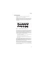
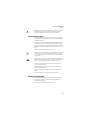
MIDI
The MIDI test performs a loop-back of the serial port by sending a 23-byte pattern over the
external MIDI link. This test requires a MIDI loop (a MIDI cable that connects two MIDI jacks).
The test will fail if a MIDI cable is not connected between two MIDI jacks. Be sure to run this test
with MIDI cables connected as follows:
Note: Be sure to use a known working MIDI cable!
1. Connect a MIDI cable to the MIDI In and MIDI out jacks and run the test.
2. Connect a MIDI cable to the MIDI In and MIDI Out/Thru jack and set the Out/Thru
switch on the rear panel to Out. Run the test.
A failure of this test could be caused by failure of the serial port, other MIDI circuitry, or a
problem on the Connector Board or the Engine Board.
LED
This test lights all the front panel LEDs. To complete the test and obtain the test result, press the
Cancel button. When the Cancel button is pressed the LEDs shut off and the test result is shown.
A failure of this test may indicate a problem with the Front Panel Board(s), related circuitry or
the Connector Board.
PCX-1 ROM
This test checks the software data (engine, boot, and setups) stored in FlashROM on the PCX-1
Board.
Failure of this test may indicate a problem with the Flash ROM chip (U5 on the PCX-1 Board),
associated circuitry, or the PCX-1 Board.
PCX-1 RW
This test is a combination of the RAM, MABEL and LISA tests. This test writes data to RAM and
the MABEL and LISA registers then confirms that the data written can be read back successfully.
A failure of this test indicates a problem with the PCX-1 Board.
PCX-1 RAM
The PCX-1 RAM test writes to the microprocessor RAM space and verifies that the write was
successful.
A failure of this test may indicate a problem with the RAM or related circuitry on the PCX-1
Board.
2-5
Diagnostics
Description of Tests
PCX-1 MABEL
This test performs a read-write of the MABEL registers and verifies that the data written can be
read back successfully.
A failure of this test may indicate a problem with a MABEL, associated circuitry or the PCX-1
Board.
PCX-1 SROM
The PCX-1 SROM test verifies that the PCX-1 MABELs can read the Sound ROMs by performing
a checksum of the Sound ROMs. The computed checksum is then compared to the stored
checksum.
A failure of this test indicates a problem with a Sound ROM (U15 or U16) or the PCX-1 Board.
2-6
Chapter 3
PC2R Disassembly/Assembly
Introduction
This chapter contains all the procedures for the disassembly and reassembly for the PC2R—as
well as instruments with factory-installed or after-market options.
Warning: If possible, save all user programs and setups before disassembly. For instructions,
refer to Saving User Data in Chapter 5, page 5-1.
Cables, Connectors
Flat Ribbon Cables
All flat ribbon cables with connectors are keyed, and therefore cannot be reversed. Most flat
ribbon cables have locking cable clips. Be sure to reapply the clips when connecting cables. Flat
ribbon cables that connect to picoflex connectors do not have locking cable clips.
Some flat ribbon cables have exposed wires that insert directly into a wire trap connector. When
disconnecting and connecting these cables, you must look for the marking on the edge of the
cable denoting Pin 1 and be sure that you match it correctly with Pin 1 on the board.
Cable Routing
In some cases, tape secures cable connections or fastens cables to the bottom enclosure. Always
peel back the tape from one side when disconnecting cables so that the tape remains properly
positioned.
Required Tools and Materials
•
•
•
•
No. 1 Phillips head screwdriver
No. 2 Phillips head screwdriver
Small flat screwdriver
Needle-nose pliers
3-1
PC2R Disassembly/Assembly
Opening the PC2R
Opening the PC2R
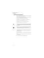
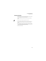
Removing the Top Cover
Before you begin disassembly, please be sure that the power is off, and that the AC power
adapter and all other cables are disconnected.
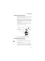
The top cover is secured to the PC2R with seven screws: three on the top, one on each side, and
two on the rear. See Figure 3-1.
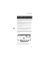
Figure 3-1
PC2R top cover
1. Remove the seven screws that secure the top cover.
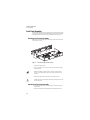
Figure 3-2
Removing the top cover
2. Refer to Figure 3-2. Slide the top cover back from the Front Panel Assembly to release the
top cover from the bottom enclosure, and place the top cover safely aside to avoid
damage.
Replacing the Top Cover
1. Place the top cover in position and slide it toward the Front Panel Assembly.
2. Install the seven screws that secure the top cover. See Figure 3-1.
3-2
PC2R Disassembly/Assembly
Opening the PC2R
Removing the Connector Board
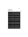
1. Following Steps 2– 5, disconnect the cables listed in Table 3-1.
Ref.
Name
Cable Type
Destination
J301
PC2 Power
stranded wire
Engine Board
J302
PC2R Audio In
flat ribbon
Engine Board
J303
MIDI/CPU
flat ribbon
Engine Board
J304
Front Panel
flat ribbon
Right Front Panel Board
J322
FP/Vol/Pwr/Hp
stranded wire
Headphone/Vol/Pwr Sw Board
Table 3-1
Connector Board cables
2. Disconnect the stranded wire cable from J301 on the Connector Board.
3. Remove the cable locking clip and disconnect the flat ribbon cable from J304. Be sure to set
the cable locking clip safely aside so that you can install it when you reconnect the cable.
4. Disconnect the stranded wire cable from J322.
5. The flat ribbon cables connected to J302 and J303 use wire trap connectors. The shielding
has been removed from these cables to expose the wires. The wires are directly inserted
into these connectors.
Lift up the sides of each connector. This unlocks the trap to free the cable wires. Gently
pull each cable up out of the connector. Note the marking (red or black) on each cable that
indicates the connection to Pin 1; you’ll need to reconnect the marked edge of the cable to
Pin 1 when you replace the Connector Board.
6. Remove the two screws that secure the MIDI jacks to the rear panel.
7. Remove the two nuts that secure the 1/4” audio out jacks to the rear panel.
8. Remove the three screws that secure the Connector Board to the bottom enclosure.
Caution: VR1 on the Connector Board is attached to the heat sink. When you remove the
Connector Board and heat sink, be sure to keep the board and heat sink stable so that you
do not damage VR1 or its connection.
9. Remove the four screws that secure the heat sink to the bottom enclosure.
10. Slide the Connector Board and heat sink away from the rear panel and toward the Front
Panel Assembly. This will free the jacks and MIDI switch from their positions on the rear
panel.
11. Tilt up the rear panel edge of the Connector Board and heat sink. Carefully lift the board
and heat sink out of the PC2R, and place them on a flat protected surface.
3-3
PC2R Disassembly/Assembly
Opening the PC2R
Replacing the Connector Board
1. Tilt down the inner edge (closest to the Front Panel Assembly) of the Connector Board and
heat sink, and place it flat on to the bottom enclosure.
2. Slide the Connector Board and heat sink toward the rear panel so that the jacks and MIDI
switch are positioned through their openings in the rear panel.
3. Install the four screws that secure the heat sink to the bottom enclosure.
4. Install the three screws that secure the Connector Board to the bottom enclosure.
5. Install the two screws that secure the MIDI jacks to the rear panel.
6. Install the two nuts that secure the 1/4” audio out jacks to the rear panel.
7. Connect the wire trap flat ribbon cables in the following order.
Caution: Be sure to look for the marking on the edge of the cable denoting Pin 1 and that
you match it correctly with Pin 1 on the board. Make certain that the wires are straight
prior to inserting them into the connector and that each wire is correctly inserted into its
respective position.
Note: Be sure the sides of the connector are lifted. Insert the flat ribbon cables into the
wire trap connectors and push down the sides of each connector to lock the cable into the
connector. Gently pull each cable to verify that it is locked into its connector.
Insert the five-wire flat ribbon cable from the Engine Board into the wire trap connector at
J302 on the Connector Board.
Insert the ten-wire flat ribbon cable from the Engine Board into the wire trap connector at
J303 on the Connector Board.
8. Connect the stranded wire cable from the Headphone/Volume/Power Switch Board to
J322.
9. Connect the flat ribbon cable from the Right Front Panel Board to J304. Be sure to install
the cable locking clip.
10. Connect the stranded wire cable from the Engine Board to J301.
3-4
PC2R Disassembly/Assembly
Opening the PC2R
Removing the Polyphony Expansion Board (PCX-1)
The Polyphony Expansion Board is mounted onto the Engine Board and held in place with four
nylon PC board standoffs and a 24-pin female connector on the underside of the board. It is also
secured to the bottom enclosure with two screws.
1. Remove the two screws that secure the PCX-1 Board to the bottom enclosure.
2. Squeeze the top of one of the four nylon PC board standoffs, and lift the corner of the
board until it clears that standoff. Repeat for the other three standoffs.
3. When the board is free of the standoffs, lift the board straight up to disconnect the 24-pin
connector from the Engine Board.
24-pin female connector
on PCX-1 board
24-pin male header
on Engine board
Figure 3-3
Removing the Polyphony Expansion Board (PCX-1)
Replacing the Polyphony Expansion Board (PCX-1)
There are two cables routed underneath the PCX-1 Board: a flat ribbon cable from the LCD to
the Engine Board, and a stranded wire cable from the Headphone/Volume/Power Switch
Board to the Connector Board. Before you replace the PCX-1 Board, be certain that these cables
are properly positioned.
1. Place the PCX-1 Board over the four standoffs. This should properly position the 24-pin
connector over the 24-pin header on the Engine Board.
2. Press the PCX-1 Board down, securing the 24-pin connector, and snapping the board onto
the standoffs.
Note: If you are installing a new PCX-1 Board, check the old board for Sound ROM
options. If the unit has Sound ROM options, be sure to install them on the new board.
3. Install the two screws that secure the PCX-1 Board to the bottom enclosure.
3-5
PC2R Disassembly/Assembly
Opening the PC2R
Removing the Engine Board
1. If the PC2R you are servicing has a PCX-1 Board installed, remove it following the
procedure described on page 3-5.
2. Following Steps 3–6, disconnect the cables listed in Table 3-2.
Ref.
Name
Cable Type
Destination
J304
Front Panel
flat ribbon
RIght Front Panel to Connector
J402
PC2 Power
stranded wire
Connector Board
J403
MIDI/CPU
flat ribbon
Connector Board
J405
Backlight
stranded wire
LCD Board
J406
LCD
flat ribbon
LCD Board
J412
PC2 Audio Out
flat ribbon
Connector Board
Table 3-2
Engine Board cables
3. Remove the cable locking clip and disconnect the flat ribbon cable from J304 on the
Connector Board. Be sure to set the cable locking clip safely aside so that you can install it
when you reconnect the cable.
4. The flat ribbon cables connected to J403 and J412 use wire trap connectors. The shielding
has been removed from these cables to expose the wires. The wires are directly inserted
into these connectors.
Lift up the sides of each connector. This unlocks the trap to free the cable wires. Gently
pull each cable up out of the connector. Note the marking (red or black) on each cable that
indicates the connection to Pin 1; you’ll need to reconnect the marked edge of the cable to
Pin 1 when you replace the Engine Board.
5. Remove the cable locking clip and disconnect the flat ribbon cable from location J406 on
the Engine Board. Be sure to set the cable locking clip safely aside so that you can install it
when you reconnect the cable.
6. Disconnect the stranded wire cables from locations J402 and J405 on the Engine Board.
7. Remove the five screws that secure the Engine Board to the bottom enclosure and remove
the Engine Board.
Replacing the Engine Board
1. Place the Engine Board on the bottom enclosure.
2. Install the five screws that secure the Engine Board to the bottom enclosure.
3. Connect the stranded wire cable from the Connector Board to J402.
4. Connect the stranded wire cable from the LCD Board to J405.
5. Connect the flat ribbon cable from the LCD Board to J406. Be sure to install the cable
locking clip.
6. Connect the wire trap flat ribbon cables in the following order.
3-6
PC2R Disassembly/Assembly
Opening the PC2R
Caution: Be sure to look for the marking on the edge of the cable denoting Pin 1 and that
you match it correctly with Pin 1 on the board. Make certain that the wires are straight
prior to inserting them into the connector and that each wire is correctly inserted into its
respective position.
Note: Be sure the sides of the connector are lifted. Insert the flat ribbon cables into the
wire trap connectors and push down the sides of each connector to lock the cable into the
connector. Gently pull each cable to verify that it is locked into its connector.
Insert the five-wire flat ribbon cable from the Connector Board into the wire trap
connector at J412 on the Engine Board.
Insert the ten-wire flat ribbon cable from the Connector Board into the wire trap connector
at J403 on the Engine Board.
7. Connect the flat ribbon cable from the Right Front Panel Board to J304 on the Connector
Board. Be sure to install the cable locking clip.
8. If you removed a PCX-1 Board, install it following the procedure on page 3-5.
3-7
PC2R Disassembly/Assembly
Front Panel Assembly
Front Panel Assembly
The Front Panel Assembly consists of the front panel faceplate, a mounting bracket for the front
panel boards, and four printed circuit boards. The boards mounted on the Front Panel Assembly
are the Right Front Panel, LCD, Left Front Panel, and Headphone/Volume/Power Switch.
Removing the Front Panel Assembly
Refer to Figure 3-4. The bottom edge of the Front Panel Assembly and front edge of the bottom
enclosure connect to form a lip.
Lip
Figure 3-4
Front Panel Assembly and bottom enclosure
1. Tilt up the front edge of the PC2R.
2. Using a #1 screwdriver, remove the four screws that secure the Front Panel Assembly to
the bottom enclosure.
Note: Before continuing, be sure that you have a soft surface to rest the Front Panel
Assembly on so that the front panel switches, jacks, and rotary potentiometers are not
damaged.
3. Slide the Front Panel Assembly forward and away from the bottom enclosure.
Caution: There are four cables connected to the Front Panel Assembly. You do not need to
disconnect these cables.
Replacing the Front Panel Assembly
1. Position the Front Panel Assembly so that its bottom edge is under the front edge of the
bottom enclosure.
2. Tilt up the front edge of the PC2R and install the four black flat head machine screws.
3-8
PC2R Disassembly/Assembly
Front Panel Assembly
Removing the Front Panel Faceplate
Note: If the service you are performing only requires that you have access to the front
panel boards for component testing, component replacement or installing a replacement
board, it is not necessary to remove the front panel faceplate. Refer to the procedure for
the front panel board you need to remove and follow the steps described.
1. Follow the procedure to remove the Front Panel Assembly.
2. Refer to Figure 3-5 on page 3-10. Four flat head machine screws secure the front panel
faceplate to the Front Panel Assembly. These screws are located along the top of the Front
Panel Assembly.
Using a #1 screwdriver, remove the four screws.
3. Place the front panel faceplate safely aside to avoid accidental damage.
Replacing the Front Panel Faceplate
1. Position the front panel faceplate onto the Front Panel Assembly.
Note: Verify that the rotary potentiometers, jacks, and switch button caps are correctly
positioned through their openings in the front panel faceplate. Turn the rotary
potentiometers to be sure that they move freely; and push the switch button caps to be
sure that their corresponding switches click.
2. Install the four flat head machine screws that secure the front panel faceplate to the Front
Panel Assembly.
Front Panel Boards
The front panel boards are secured to a mounting bracket. This bracket is secured to the front
panel faceplate.
If the service you are performing only requires that you have access to the front panel boards for
component testing, component replacement or installing a replacement board, it is not necessary
to remove the front panel faceplate or remove the boards from the mounting bracket.
Figure 3-5 shows the position of the boards on the Front Panel Assembly and the placement of
the front panel faceplate screws located above the boards. Refer to the procedure for the front
panel board you need to remove and follow the steps described.
3-9
PC2R Disassembly/Assembly
Front Panel Assembly
crews
late s
facep
Headphone/Volume/
Power Switch Board
Left Front
Panel Board
LCD
Board
Right Front
Panel Board
Figure 3-5
Front panel faceplate screw locations
Removing the Right Front Panel Board
1. Remove the Front Panel Assembly, as described on page 3-8. It is not necessary to
disconnect all the cables that connect the Front Panel Assembly boards to boards located
on the bottom enclosure.
2. Remove the cable locking clip and disconnect the flat ribbon cable from J601 on the Right
Front Panel Board.
3. Disconnect the flat ribbon cable from J602. This cable uses a picoflex molex connector. To
disconnect it, grip the connector and pull it out straight.
Caution: Do not wiggle the connector back and forth. Doing so, could cause damage to
the header.
Note: Be aware of the marking (red or black) on the cable that indicates the connection to
Pin 1; you’ll need to reconnect the marked edge of the cable to Pin 1 when you replace the
board.
4. It is not necessary to remove the front panel faceplate to remove the Right Front Panel
Board. Two of the screws that secure the front panel faceplate to the Front Panel Assembly
are located above the Right Front Panel Board. Refer to Figure 3-5 and remove the two
screws.
5. Remove the three screws that secure the Right Front Panel Board to the mounting bracket,
and remove the Right Front Panel Board.
3-10
PC2R Disassembly/Assembly
Front Panel Assembly
Replacing the Right Front Panel Board
1. Place the Right Front Panel Board in position on the mounting bracket and line up the
screw holes.
Note: Verify that the rotary potentiometers and switch button caps are correctly
positioned through their openings in the front panel faceplate. Turn the rotary
potentiometers to be sure that they move freely; and push the switch button caps to be
sure that their corresponding switches click.
2. Install the three screws that secure the board to the mounting bracket.
3. Install the two screws that secure the front panel faceplate.
4. Connect the flat ribbon cable from the Connector Board to Right Front Panel Board,
location J601. Be sure to install the cable locking clip.
5. Connect the flat ribbon cable from the Left Front Panel Board to the Right Front Panel
Board, location J602.
Caution: The side walls of the picoflex header are different. The Pin 1 side is slightly
wider than the other side; and the corresponding sides of the connector incorporate the
differences. When you connect the cable, be sure to orient the marking (red or black) on
the cable that indicates the connection to Pin 1 on the board to prevent damage to the
header or a failure caused by an improper connection.
6. Follow the procedure on page 3-8 to install the Front Panel Assembly.
Removing the LCD Board
1. Remove the Front Panel Assembly, as described on page 3-8. It is not necessary to
disconnect all the cables that connect the Front Panel Assembly boards to boards located
on the bottom enclosure.
2. Disconnect the stranded wire cable soldered to the LCD Board from location J405 on the
Engine Board.
3. Remove the locking cable clip and disconnect the flat ribbon cable soldered to the LCD
Board from location J406 on the Engine Board. If the unit you are servicing has a PCX-1
Board installed, this cable is routed underneath the PCX-1 Board.
After you disconnect the cable, carefully slide it so that it is positioned close to the left
edge of the PCX-1 Board (left edge as viewed standing at the front panel). Gently pull the
cable toward the Front Panel Assembly to completely free it from underneath the PCX-1
Board.
4. It is not necessary to remove the front panel faceplate to remove the LCD Board. One
screw that secures the faceplate to the Front Panel Assembly is located above the LCD
Board. Refer to Figure 3-5 and remove the screw.
5. Remove the two screws that secure the LCD Board to the mounting bracket, and remove
the LCD.
3-11
PC2R Disassembly/Assembly
Front Panel Assembly
Replacing the LCD Board
1. Place the LCD Board in position over the mounting standoffs on the mounting bracket.
2. Install the two screws that secure the LCD Board to the mounting bracket.
3. Install the screw that secures the front panel faceplate to the Front Panel Assembly.
4. Connect the stranded wire cable from the LCD Board to location J405 on the Engine
Board.
5. If the unit you are servicing has a PCX-1 Board installed, route the flat ribbon cable
beneath the board and connect it to location J406 on the Engine Board. Be sure to install
the cable locking clip.
6. Follow the procedure on page 3-8 to install the Front Panel Assembly.
Removing the Left Front Panel Board
1. Remove the Front Panel Assembly, as described on page 3-8. It is not necessary to
disconnect all the cables that connect the Front Panel Assembly boards to boards located
on the bottom enclosure.
2. Disconnect the flat ribbon cable from J603. This cable uses a picoflex molex connector. To
disconnect it, grip the connector and pull it out straight.
Caution: Do not wiggle the connector back and forth. Doing so, could cause damage to
the header.
Note: Be aware of the marking (red or black) on the cable that indicates the connection to
Pin 1; you’ll need to reconnect the marked edge of the cable to Pin 1 when you replace the
board.
3. It is not necessary to remove the front panel faceplate to remove the Left Front Panel
Board. One screw that secures the front panel faceplate to the Front Panel Assembly is
located above the Left Front Panel Board. Refer to Figure 3-5 and remove the screw.
4. Remove the two screws that secure the Left Front Panel Board to the mounting bracket.
5. Refer to Figure 3-6. This illustration shows the location of a soldered connection between
the Left Front Panel and Headphone/Volume/Power Switch Boards. To remove the
board, desolder this connection from the Left Front Panel Board.
Note: This illustration shows the Headphone/Volume/Power Switch Board lying flat to
indicate the connection between it and the Left Front Panel Board. In its normal position,
it is perpendicular to the Left Front Panel Board.
3-12
PC2R Disassembly/Assembly
Front Panel Assembly
HP/Vol/Pwr Sw
Board
Left Front Panel Board
J603
1
Circuit side
J604
1
J1
J2
soldered
connection
Figure 3-6
6.
Left Front Panel and Headphone/Volume/Power Switch Board
connection
Remove the Left Front Panel Board.
Replacing the Left Front Panel Board
1. Place the Left Front Panel Board in position on the mounting bracket and line up the
screw holes.
2. Install the two screws that secure the board to the mounting bracket.
Note: Verify that the rotary potentiometers and switch button caps are correctly
positioned through their openings in the front panel faceplate. Turn the rotary
potentiometers to be sure that they move freely; and push the switch button caps to be
sure that their corresponding switches click.
3. Install the screw that secures the front panel faceplate.
4. Connect the flat ribbon cable from the Right Front Panel Board to the Left Front Panel
Board, location J603.
Caution: The side walls of the picoflex header are different. The Pin 1 side is slightly
wider than the other side; and the corresponding sides of the connector incorporate the
differences. When you connect the cable, be sure to orient the marking (red or black) on
the cable that indicates the connection to Pin 1 on the board to prevent damage to the
header, connector or a failure caused by an improper connection.
5. Refer to Figure 3-6. Solder the wire connection from the Headphone/Volume/Power
Switch Board to the location indicated on the Left Front Panel Board.
6. Follow the procedure on page 3-8 to install the Front Panel Assembly.
3-13
PC2R Disassembly/Assembly
Front Panel Assembly
Removing the Headphone/Volume/Power Switch Board
1. Remove the Front Panel Assembly, as described on page 3-8. It is not necessary to
disconnect all the cables that connect the Front Panel Assembly boards to boards located
on the bottom enclosure.
2. Follow the procedure on page 3-9 to remove the front panel faceplate.
3. Disconnect the stranded wire cable that connects the Headphone/Volume/Power Switch
Board to the Connector Board.
4. Remove the nut and flat washer that secure the headphone jack to the front panel
mounting plate.
5. Remove the volume knob.
6. Remove the nut and flat washer that secure the volume/power switch to the front panel
mounting plate.
7. Refer to Figure 3-6. This illustration shows the location of a soldered connection between
the Left Front Panel and Headphone/Volume/Power Switch Boards. To remove the
board, desolder this connection from the Headphone/Volume/Power Switch Board.
Note: This illustration shows the Headphone/Volume/Power Switch Board lying flat to
indicate the connection between it and the Left Front Panel Board. In its normal position,
it is perpendicular to the Left Front Panel Board.
8. Remove the Headphone/Volume/Power Switch Board.
Replacing the Headphone/Volume/Power Switch Board
1. Position the Headphone/Volume/Power Switch Board on the mounting bracket.
2. Install the nut and washer that secure the headphone jack to the mounting bracket.
3. Install the nut and washer that secure the volume/power switch to the mounting bracket.
4. Install the volume knob.
5. Refer to Figure 3-6. Solder the wire connection from the Left Front Panel Board to Pin 5 of
J2 on the Headphone/Volume/Power Switch Board.
6. Follow the procedure on page 3-9 to install the front panel faceplate.
Note: Be sure that the Volume/Power Switch moves freely.
7. Follow the procedure on page 3-8 to install the Front Panel Assembly.
3-14
Chapter 4
PC2/PC2X Disassembly/Assembly
Introduction
This chapter contains all the procedures for the disassembly and reassembly of both the 76-note
PC2 and the 88-note PC2X—as well as instruments with factory-installed or after-market
options. There are five main sections: Opening the PC2/PC2X, Top Enclosure, PC2 Keyboard
Assembly, and PC2X Keyboard Assembly.
Warning: If possible, save all user programs and setups before disassembly. For instructions,
refer to Saving User Data in Chapter 5, page 5-1.
Notes, Cautions, Warnings
Please pay special attention to all Notes, Cautions, and Warnings as they not only point out
specific instructions, but also alert you to differences between the 76-note PC2 keyboard and the
88-note PC2X keyboard.
Cables, Connectors
Flat Ribbon Cables
All flat ribbon cables with connectors are keyed, and therefore cannot be reversed. Most flat
ribbon cables have locking cable clips. Be sure to reapply the clips when connecting cables.
Some flat ribbon cables have exposed wires that insert directly into a wire trap connector. When
disconnecting and connecting these cables, you must look for the marking on the edge of the
cable denoting Pin 1 and be sure that you match it correctly with Pin 1 on the board.
Cable Routing
In some cases, tape secures cable connections or fastens cables to the bottom enclosure. Always
peel back the tape from one side when disconnecting cables so that the tape remains properly
positioned.
Required Tools and Materials
•
•
•
•
•
•
•
No. 1 Phillips head screwdriver
No. 2 Phillips head screwdriver
Small flat screwdriver
Dowel (3mm diameter)
Needle-nose pliers
Small blunt-end tool (Q-Tip, toothpick, etc.)
Foam blocks
4-1
PC2/PC2X Disassembly/Assembly
Opening the PC2/PC2X
Opening the PC2/PC2X
PC2 Bottom
Refer to Figure 4-1. Arrows indicate the locations of the enclosure support wall, endcap and rear
panel screws.
Endcap screws
Endcap screws
Keyboard
Enclosure support wall screws
Access panel
*
*
Rear panel screws
Rear panel
*Endcap locking bracket screws
Figure 4-1
PC2 bottom enclosure
Caution: Do not remove the endcap or rear panel screws at this point of the procedure.
1. Tilt the PC2 up and remove the eight enclosure support wall screws.
2. Place the unit flat on your work surface.
3. Move the unit so that the rear panel portion of the unit hangs over the edge of your work
surface. This gives you access to the seven screws that secure the rear panel portion of the
top enclosure to the bottom enclosure. Remove the seven screws.
Note: Two of the rear panel screws also secure the rear panel portion of the access panel.
It is not necessary to remove the five remaining access panel screws.
4. Slide the unit back onto the work surface.
4-2
PC2/PC2X Disassembly/Assembly
Opening the PC2/PC2X
PC2X Bottom
Refer to Figure 4-2. Arrows indicate the locations of the enclosure support wall, endcap and rear
panel screws.
Endcap screws
Endcap screws
Keyboard
Enclosure support wall screws
Access panel
*
*
Rear panel screws
Rear panel
*Endcap locking bracket screws
Figure 4-2
PC2X bottom enclosure
Caution: Do not remove the endcap or rear panel screws at this point of the procedure.
1. Tilt the PC2X up and remove the eight enclosure support wall screws.
2. Place the unit flat on your work surface.
3. Move the unit so that the rear panel portion of the unit hangs over the edge of your work
surface. This gives you access to the nine screws that secure the rear panel portion of the
top enclosure to the bottom enclosure. Remove the nine screws.
Note: Two of the rear panel screws also secure the rear panel edge of the access panel. It is
not necessary to remove the five remaining access panel screws.
4. Slide the unit back onto the work surface.
4-3
PC2/PC2X Disassembly/Assembly
Opening the PC2/PC2X
Removing the Top Enclosure
1. Depending on the unit you are servicing, follow the procedures described on page 4-2 for
the PC2 bottom or page 4-3 for the PC2X bottom.
2. Refer to Figure 4-3.
Note: Figure 4-3 is an illustration of the PC2 rear panel. An illustration of the PC2X has
not been included because the difference between the two is minimal. The quantity and
position of the endcap screws is identical.
3. Remove the four screws that secure the endcaps to the rear panel.
Endcap screws
Power
I / 0
MIDI
Adapter In
Thru / Out
Pedals
In
Thru / Out
Out
LCD
Contrast
Digital
Out
9.0V 2.0A
14.0V~0.25A
Switch
1
Inputs
2
3
Continuous
1
Breath
2
Audio Outs
Ribbon
Left
Right
Headphones
THIS DEVICE COMPLIES WITH PART 15 OF THE FCC RULES. OPERATION IS SUBJECT TO THE FOLLOWING TWO CONDITIONS: (1) THIS DEVICE MAY NOT CAUSE HARMFUL
INTERFERENCE, AND (2) THIS DEVICE MUST ACCEPT ANY INTERFERENCE RECEIVED, INCLUDING INTERFERENCE THAT MAY CAUSE UNDESIRED OPERATION.
Manufacturer: Young Chang Co., LTD.
Made in ROK
Serial No.
PC2
Endcap screws
Figure 4-3
PC2 rear panel
Caution: The following steps describe removing the left and right endcaps. To avoid
damage to the endcaps, be sure to hold onto each endcap when removing the screws.
When the endcap screws are removed, the endcap is free of the unit.
4. Refer to Figure 4-1 for the PC2 or Figure 4-2 for the PC2X. Move the unit so that one end
hangs over the edge of your work surface. Remove the four endcap screws from the
bottom enclosure. One of these screws secures the endcap locking bracket. When you
remove the endcap locking bracket screw, the bracket remains loosely in the endcap
assembly. Set the endcap safely aside. Repeat for the other endcap.
5. Refer to Figure 4-4. The bottom edge of the rear panel and back edge of the bottom
enclosure connect to form a lip. The rear panel screws secure the lip.
Note: Figure 4-4 is an illustration of the PC2. An illustration of the PC2X has not been
included because the difference between the two is minimal. The only difference is the
spacing and quantity of the rear panel screws. If you are servicing a PC2, there are seven
screws securing the rear panel portion of the top enclosure to the bottom enclosure. If you
are servicing a PC2X, there are nine screws.
4-4
PC2/PC2X Disassembly/Assembly
Opening the PC2/PC2X
Rea
r pa
nel
w
scre
loca
tion
s
Lip
Figure 4-4
Top cover and bottom enclosure
Warning: Be sure to have your work surface prepared. This includes
placing foam blocks behind the unit. When the top enclosure is removed,
place it on the foam blocks to avoid damaging the Alpha Wheel, control
panel buttons, and sliders. The following procedure requires enough room
behind the rear of the unit to place the top enclosure face down on your
work surface.
6. Grip each end of the top enclosure and rotate it back approximately two inches. This
separates the bottom edges of the top enclosure and bottom enclosure.
7. Lift the top enclosure straight up.
8. Turn the top enclosure over and place it face down onto your work surface.
Caution: Table 4-1 lists the cables, by board location, from the top enclosure to the assembly
they connect to on the bottom enclosure. You do not need to disconnect these cables.
Top cover Assembly
Connector Board
Bottom Enclosure
Keyboard Assembly
Connector Board
Keyboard Assembly
FP Board
Button Board/Wheel Assembly
Connector Board
Mod Wheel Assembly
Table 4-1
Top cover and bottom enclosure cables
4-5
PC2/PC2X Disassembly/Assembly
Opening the PC2/PC2X
Replacing the Top Enclosure
1. Position the top enclosure behind the bottom enclosure.
2. Move the top enclosure so that the bottom edge of the rear panel is positioned under the
bottom enclosure edge. See Figure 4-4 on page 4-5.
Note: Verify that the cables listed in Table 4-1 are lying flat on the bottom enclosure. Be
sure that all other cables are tucked between the top enclosure and the enclosure support
walls.
3. Hold the top enclosure safely in place and move the unit so that one end of the rear panel
edge hangs over the edge of your work surface and install the rear panel screw at that end.
Slide the unit back onto your work surface. Repeat for other end. Refer to Figure 4-1 for
the PC2 or Figure 4-2 for the PC2X.
Warning: Perform Steps 3 and 4 separately. Combining these steps could cause the top
enclosure to flip away from the bottom enclosure or off of your work surface.
4. Move the unit so that the rear panel edge of the unit hangs over the edge of your work
surface and install the remaining screws.
Note: If you are servicing a PC2, there are five remaining rear panel screws to install. If
you are servicing a PC2X, there are seven remaining screws.
Closing the PC2/PC2X
Warning: The following procedure assumes that you have completed Steps 3 and 4 in
Replacing the Top Enclosure. If you have not completed these steps, do so before continuing.
1. Refer to Figure 4-1 for the PC2 or Figure 4-2 for the PC2X. Tilt the unit up and install the
eight enclosure support wall screws.
2. Slide one side of the unit off of your work surface and hold the appropriate endcap in
position. Install the four endcap screws in the bottom enclosure. Repeat for the other
endcap.
3. Refer to Figure 4-3. Install the four endcap screws in the rear panel.
4-6
PC2/PC2X Disassembly/Assembly
Top Enclosure
Top Enclosure
The top enclosure includes five boards: Connector, Front Panel, LCD, Slider, and Engine. The
Right and Left Enclosure Support Walls are also included on the top enclosure. Figure 4-5 shows
the placement of the enclosure support walls. Figure 4-6 shows the placement of the boards.
Left Enclosure Support Wall
Right Enclosure Support Wall
Figure 4-5
Top enclosure, enclosure support walls
Engine Board
Slider Board
LCD Board
Front Panel Board
Connector Board
Figure 4-6
Top enclosure, board locations
4-7
PC2/PC2X Disassembly/Assembly
Top Enclosure
Removing the Enclosure Support Walls
Left Enclosure Support Wall
1. Remove the four screws that secure the left enclosure support wall to the top enclosure,
and remove the left enclosure support wall.
Right Enclosure Support Wall
1. Remove the six screws that secure the right enclosure support wall to the top enclosure,
and remove the right enclosure support wall.
Replacing the Enclosure Support Walls
Left Enclosure Support Wall
1. Align the center screw holes of the three-hole groupings in the left enclosure support wall
with the thread marks in the extrusion.
2. Install the four screws that secure the left enclosure support wall to the top enclosure.
Right Enclosure Support Wall
1. Align the center screw holes of the three-hole groupings in the right enclosure support
wall with the thread marks in the extrusion.
2. Install the six screws that secure the right enclosure support wall to the top enclosure.
Removing the Connector Board
1. Follow the procedure described on page 4-8 to remove the right enclosure support wall.
2. Following Steps 3–5, disconnect the cables listed in Table 4-2.
Ref.
Name
Cable Type
Destination
J301
PC2 Power
stranded wire
Engine Board
J302
Audio
flat ribbon
Engine Board
J303
MIDI/CPU
flat ribbon
Engine Board
J304
Front Panel
flat ribbon
Front Panel Board
J305
Slider
flat ribbon
Slider Board
J306
Treble
flat ribbon
Keyboard Assembly
J307
Bass
flat ribbon
Keyboard Assembly
J308
Wheels
flat ribbon
Mod Wheel Assembly
Table 4-2
Connector Board cables
3. Disconnect the stranded wire cable from J301 on the Connector Board.
4-8
PC2/PC2X Disassembly/Assembly
Top Enclosure
4. Remove the cable locking clips and disconnect the flat ribbon cables from J304, J306, and
J307. Be sure to set the cable locking clips safely aside so that you can install them when
you reconnect the cables.
Note: The cables used throughout the PC2/PC2X are bundled and routed so that their
locations and destinations seem obvious. However, to avoid reversing the Bass and Treble
cables when reconnecting, mark one or both cables designating B for Bass and T for
Treble.
5. The flat ribbon cables connected to J302, J303, J305, and J308 use wire trap connectors. The
shielding has been removed from the end of these cables to expose the wires. The wires
are directly inserted into these connectors.
Lift up the sides of each connector. This unlocks the trap to free the cable wires. Gently
pull each cable up out of the connector. Note the marking (red or black) on each cable that
indicates the connection to Pin 1; you’ll need to reconnect the marked edge of the cable to
Pin 1 when you replace the Connector Board.
6. Remove the five screws that secure the Connector Board to the rear panel. Two of these
screws are longer than the others and have spacers located between the screw and the rear
panel. See Figure 4-7 for the locations of the screws and spacers.
Note: Do not remove any other hardware from this portion of the rear panel.
Power
I / 0
MIDI
Adapter In
Thru / Out
Pedals
In
Thru / Out
Out
LCD
Contrast
Digital
Out
Switch
1
Inputs
2
3
Continuous
1
Breath
2
Audio Outs
Ribbon
Left
Right
Headphones
9.0V 2.0A
14.0V~0.25A
MIDI jack screws
*
*
* longer screws with spacers
Figure 4-7
Rear panel hardware locations
7. Remove the two screws that secure the MIDI jacks to the rear panel. See Figure 4-7.
8. Remove the Connector Board.
4-9
PC2/PC2X Disassembly/Assembly
Top Enclosure
Replacing the Connector Board
1. Hold the Connector Board and position it so that the power switch, LCD Contrast
potentiometer, and the rear panel jacks are correctly positioned through the rear panel
portion of the top enclosure.
2. Install the two screws that secure the MIDI jacks to the rear panel. See Figure 4-7.
3. Install the five screws that secure the Connector Board to the rear panel. Be sure to place a
spacer and use one of the longer screws at the locations noted in Figure 4-7.
4. Connect the wire trap flat ribbon cables in the following order.
Caution: Be sure to look for the marking on the edge of the cable denoting Pin 1 and that
you match it correctly with Pin 1 on the board. Make certain that the wires are straight
prior to inserting them into the connector and that each wire is correctly inserted into its
respective position.
Note: Be sure the sides of the connector are lifted. Insert the flat ribbon cables into the
wire trap connectors and push down the sides of each connector to lock the cable into the
connector. Gently pull each cable to verify that it is locked into its connector.
Insert the five-wire flat ribbon cable from the Engine Board into the wire trap connector at
J302 on the Connector Board.
Insert the seven-wire flat ribbon cable from the Slider Board into the wire trap connector
at J305 on the Connector Board.
Insert the six-wire flat ribbon cable from the Mod Wheel Assembly into the wire trap
connector at J308 on the Connector Board.
Insert the ten-wire flat ribbon cable from the Engine Board into the wire trap connector at
J303 on the Connector Board.
5. Connect the flat ribbon cables from the Keyboard Assembly to J306 and J307. Be sure to
install a cable locking clip on each connector.
6. Connect the flat ribbon cable from the Front Panel Board to J304 on the Connector Board.
Be sure to install a cable locking clip on the connector.
7. Connect the stranded wire cable from the Engine Board to J301 on the Connector Board.
8. Follow the procedure on page 4-8 to install the right enclosure support wall.
Removing the Front Panel Board
1. Follow the procedure described on page 4-8 to remove the right enclosure support wall.
2. Follow the procedure described on page 4-8 to remove the Connector Board.
3. Following Steps 4 and 5, disconnect the cables listed in Table 4-3.
4-10
PC2/PC2X Disassembly/Assembly
Top Enclosure
Ref.
Name
Cable Type
Destination
J601
IBBB
flat ribbon
Button Board/Wheel Assembly
J602
FP Bridge
flat ribbon
Slider Board
Table 4-3
Front Panel Board cables
4. The flat ribbon cables connected to J601 and J602 use wire trap connectors. The shielding
has been removed from the end of these cables to expose the wires. The wires are directly
inserted into these connectors.
Lift up the sides of each connector. This unlocks the trap to free the cable wires. Gently
pull each cable up out of the connector. Note the marking (red or black) on each cable that
indicates the connection to Pin 1; you’ll need to reconnect the marked edge of the cable to
Pin 1 when you replace the Front Panel Board.
5. Remove the cable locking clip and disconnect the flat ribbon cable at J604 on the Front
Panel Board. Be sure to set the cable locking clip safely aside so that you can install it
when you reconnect the cable.
Note: The flat ribbon cable at location J604 was disconnected following the procedure to
remove the Connector Board. It is not necessary to disconnect it from the Front Panel
Board. However, if you are replacing the Front Panel Board with a replacement board, be
sure to disconnect the cable and connect it to the replacement board.
6. Five of the screws that secure the right enclosure support wall also secure the front panel
edge of the Front Panel Board. You have already removed the enclosure support wall, but
two screws remain securing this edge of the board. See Figure 4-8, and remove the two
remaining screws.
PC board clamps and screws
J601
J604
J602
Front panel edge screws
Figure 4-8
Front Panel Board, screw locations
7. Remove the six screws that secure the three PC board clamps (two screws per clamp).
These screws also secure the rear panel edge of the Front Panel Board.
4-11
PC2/PC2X Disassembly/Assembly
Top Enclosure
The LCD is mounted onto a bezel that is secured to the Front Panel Board with small pegs
that snap into holes on the Front Panel Board. Removing the LCD requires cutting the tie
wraps that bundle the LCD cables to cable mounts positioned along the rear panel. It is
not necessary to remove the LCD from the unit. Remove the four screws that secure the
LCD to the front panel bezel. Lift the LCD up from the bezel and fold it over so that the
circuit side of the LCD is positioned above the Slider Board. For protection, place a piece
of anti-static material between the LCD and Slider Boards.
8. Lift the Front Panel Board up from the top enclosure. The spinknob and switch button
caps should remain in place.
Caution: Each switch button cap uses a set of small pegs to mount the cap to the Front
Panel Board. The button caps are mounted individually or in clusters. If a cap becomes
separated from the board, be careful that a peg is not inadvertently broken.
Replacing the Front Panel Board
1. Position the Front Panel Board onto the top enclosure, then raise the top enclosure up
slightly to verify that the spinknob and switch button caps are correctly positioned
through their openings in the top enclosure.
2. Align the center screw holes of the three-hole groupings on the front panel edge of the
board with the thread marks in the extrusion and install the two screws that secure the
front panel edge. See Figure 4-8.
3. Place a PC board clamp in position. Align the center screw holes of the clamp with the
thread marks in the extrusion and install the two screws that secure the clamp. Repeat for
the other two clamps.
4. Position the LCD onto the front panel bezel and install the four screws that secure it to the
bezel.
5. Connect the wire trap flat ribbon cables in the following order.
Caution: Be sure to look for the marking on the edge of the cable denoting Pin 1 and that
you match it correctly with Pin 1 on the board. Make certain that the wires are straight
prior to inserting them into the connector and that each wire is correctly inserted into its
respective position.
Note: Be sure the sides of the connector are lifted. Insert the flat ribbon cables into the
wire trap connectors and push down the sides of each connector to lock the cable into the
connector. Gently pull each cable to verify that it is locked into its connector.
Insert the five-wire flat ribbon cable from the Button Board into the wire trap connector at
J601 on the Front Panel Board.
Insert the eight-wire flat ribbon cable from the Slider Board into the wire trap connector at
J602 on the Front Panel Board.
6. If you have disconnected the flat ribbon cable from J604, reconnect it. Be sure to install the
cable locking clip.
7. Follow the procedure on page 4-10 to install the Connector Board.
8. Follow the procedure on page 4-8 to install the right enclosure support wall.
4-12
PC2/PC2X Disassembly/Assembly
Top Enclosure
Removing the LCD Board
1. Follow the procedure described on page 4-8 to remove the right enclosure support wall.
2. Disconnect the stranded wire from location J405 on the Engine Board.
3. Remove the cable locking clip and disconnect the flat ribbon cable from J406 on the Engine
Board. Be sure to set the cable locking clip safely aside so that you can install it when you
reconnect the cable.
4. Removing the LCD Board requires cutting the tie wraps that bundle the LCD cables to
cable mounts positioned along the rear panel. Cut the tie wraps at the cable mounts that
the two LCD cables pass through.
5. Remove the four screws that secure the LCD to the front panel bezel.
6. Lift the LCD Board up and remove it.
Caution: Be sure that the LCD cables are not tangled with other cables routed along the
rear panel.
Replacing the LCD Board
1. Place the LCD Board in position face down onto the front panel bezel.
2. Install the four screws that secure it to the front panel bezel.
3. Connect the stranded wire cable to J405 on the Engine Board.
4. Connect the flat ribbon cable to J406 on the Engine Board. Be sure to install the cable
locking clip.
5. Position the LCD cables at the cable mounts on the rear panel and install new tie wraps
through the cable mounts to bundle the cables.
Caution: Be sure that you have bundled the LCD cables with the other cables positioned
at the cable mounts.
6. Follow the procedure on page 4-8 to install the right enclosure support wall.
Removing the Polyphony Expansion Board (PCX-1)
The Polyphony Expansion Board is mounted on to the Engine Board and held in place with four
nylon PC board standoffs and a 24-pin female header on the underside of the board.
1. Follow the procedure described on page 4-8 to remove the left enclosure support wall.
2. Squeeze the top of one of the four nylon PC board standoffs, and lift the corner of the
board until it clears that standoff. Repeat for the other three standoffs.
3. When the board is free of the standoffs, lift the board straight up to disconnect the 24-pin
connector from the Engine Board.
4-13
PC2/PC2X Disassembly/Assembly
Top Enclosure
Replacing the Polyphony Expansion Board (PCX-1)
1. Place the PCX-1 Board over the four standoffs. This should properly position the 24-pin
connector over the 24-pin header on the Engine Board.
2. Press the PCX-1 Board down, securing the 24-pin connector, and snapping the board onto
the standoffs.
Note: If you are installing a new PCX-1 Board, check the old board for Sound ROM
options. If the unit has Sound ROM options, be sure to install them on the new board.
3. Follow the procedure described on page 4-8 to install the left enclosure support wall.
Removing the Slider Board
1. Follow the procedure described on page 4-8 to remove the left enclosure support wall.
2. If the unit you are servicing has a PCX-1 Board installed, follow the procedure on
page 4-13 to remove it.
3. The flat ribbon cables connected to J101 and J102 use wire trap connectors. The shielding
has been removed from the end of these cables to expose the wires. The wires are inserted
directly into these connectors.
Lift up the sides of each connector. This unlocks the trap to free the cable wires. Gently
pull each cable up out of the connector. Note the marking (red or black) on each cable that
indicates the connection to Pin 1; you’ll need to reconnect the marked edge of the cable to
Pin 1 when you replace the Slider Board.
4. Two of the screws that secure the left enclosure support wall also secure the front panel
edge of the Slider Board. You have already removed the enclosure support wall, but one
screw remains securing this edge of the board. See Figure 4-9, and remove the remaining
screw.
PC board clamp and screws
J101
J102
Front panel edge screw
Figure 4-9
Slider Board, screw locations
5. Remove the two screws that secure the PC board clamp and rear panel edge of the Slider
Board to the top enclosure.
6. Remove the Slider Board. The slider knobs, slider bezels, and switch button caps should
remain in place.
4-14
PC2/PC2X Disassembly/Assembly
Top Enclosure
Caution: Each switch button cap uses a set of small pegs to mount the cap to the Slider
Board. The button caps are mounted individually or in clusters. If a cap becomes
separated from the board, be careful that a peg is not inadvertently broken.
Replacing the Slider Board
1. Position the Slider Board onto the top enclosure. Raise the top enclosure up slightly to
verify that the slider knobs and switch button caps are correctly positioned through their
openings in the top enclosure.
2. Align the center screw hole on front panel edge with the thread marks in the extrusion
and install the screw that secures the front panel edge of the Slider Board. See Figure 4-9.
3. Place the PC board clamp in position. Align the center screw holes of the PC board clamp
with the thread marks in the extrusion and install the two screws that secure the PC board
clamp.
4. Connect the wire trap flat ribbon cables in the following order.
Caution: Be sure to look for the marking on the edge of the cable denoting Pin 1 and that
you match it correctly with Pin 1 on the board. Make certain that the wires are straight
prior to inserting them into the connector and that each wire is correctly inserted into its
respective position.
Note: Be sure the sides of the connector are lifted. Insert the flat ribbon cables into the
wire trap connectors and push down the sides of each connector to lock the cable into the
connector. Gently pull each cable to verify that it is locked into its connector.
Insert the seven-wire flat ribbon cable from the Connector Board into the wire trap
connector at J101 on the Slider Board.
Insert the eight-wire flat ribbon cable from the Front Panel Board into the wire trap
connector at J102 on the Slider Board.
5. If the unit you are servicing has a PCX-1 Board, follow the procedure on page 4-13 to
install it.
6. Follow the procedure on page 4-8 to install the left enclosure support wall.
Removing the Engine Board
1. Follow the procedure described on page 4-8 to remove the left enclosure support wall.
2. If the unit you are servicing has a PCX-1 Board installed, remove it following the
procedure described on page 4-13.
3. Following Steps 4–6, disconnect the cables listed in Table 4-4.
4-15
PC2/PC2X Disassembly/Assembly
Top Enclosure
Ref.
Name
Cable Type
Destination
J402
PC2 PWR
stranded wire
Connector Board
J403
MIDI & CPU
flat ribbon
Connector Board
J405
Backlight
stranded wire
LCD Board
J406
LCD
flat ribbon
LCD Board
J412
PC2 Audio Out
flat ribbon
Connector Board
Table 4-4
Engine Board cables
4. The flat ribbon cables connected to J403 and J412 use wire trap connectors. The shielding
has been removed from the end of these cables to expose the wires. The wires are inserted
directly into these connectors.
Lift up the sides of each connector. This unlocks the trap to free the cable wires. Gently
pull each cable up out of the connector. Note the marking (red or black) on each cable that
indicates the connection to Pin 1; you’ll need to reconnect the marked edge of the cable to
Pin 1 when you replace the Engine Board.
5. Disconnect the stranded wire cables from J402 and J405.
6. Remove the cable locking clip and disconnect the flat ribbon cable from J406. Be sure to set
the cable locking clip safely aside so that you can install it when you reconnect the cable.
7. Two of the screws that secure the left enclosure support wall also secure the front panel
edge of the Engine Board. You have already removed the enclosure support wall, but one
screw remains securing this edge of the board. See Figure 4-10, and remove the remaining
screw.
PC board clamp and screws
J406
J405
J402
J412
J403
Front panel edge screw
Figure 4-10
Engine Board, screw locations
8. Remove the two screws that secure the PC board clamp and rear panel edge of the Engine
Board to the top enclosure.
9. Remove the Engine Board.
4-16
PC2/PC2X Disassembly/Assembly
Top Enclosure
Replacing the Engine Board
1. Place the Engine Board in position on the top enclosure.
2. Align the center screw hole on the front panel edge with the thread marks in the extrusion
and install the screw that secures the front panel edge. See Figure 4-10.
3. Place the PC board clamp in position. Align the center screw holes of the PC board clamp
with the thread marks in the extrusion and install the two screws that secure the PC board
clamp.
4. Connect the flat ribbon cable from the LCD to J406 on the Engine Board. Be sure to install
the cable locking clip.
5. Connect the stranded wire cable from the LCD to J405 on the Engine Board.
6. Connect the stranded wire cable from the Connector Board to J402 on the Engine Board.
7. Connect the wire trap flat ribbon cables in the following order.
Caution: Be sure to look for the marking on the edge of the cable denoting Pin 1 and that
you match it correctly with Pin 1 on the board. Make certain that the wires are straight
prior to inserting them into the connector and that each wire is correctly inserted into its
respective position.
Note: Be sure the sides of the connector are lifted. Insert the flat ribbon cables into the
wire trap connectors and push down the sides of each connector to lock the cable into the
connector. Gently pull each cable to verify that it is locked into its connector.
Insert the ten-wire flat ribbon cable from the Connector Board into the wire trap connector
at J403 on the Engine Board.
Insert the five-wire flat ribbon cable from the Connector Board into the wire trap
connector at J412 on the Engine Board.
8. If the unit you are servicing has a PCX-1 Board, follow the procedure on page 4-13 to
install it.
9. Follow the procedure on page 4-8 to install the left enclosure support wall.
Removing the Mod Wheel Assembly
1. Refer to Figure 4-11 on page 4-19. Slide the left side of the unit forward off of your work
surface so that you can access the four screws and washers securing the assembly to the
bottom enclosure. Remove the four screws and washers.
2. Slide the unit back onto your work surface.
3. Lift the Mod Wheel Assembly up, approximately two inches. Nylon reinforced tape
secures the Aftertouch flex cable(s) to the bottom enclosure. Peel back the tape from one
side and disconnect the cable(s).
Note: If you are servicing a PC2, one flat flex cable attaches to the Mod Wheel Assembly,
location J202. If you are servicing a PC2X, two flat flex cables attach to the Mod Wheel
Assembly, locations J202 and J203.
4-17
PC2/PC2X Disassembly/Assembly
Top Enclosure
4. The flat ribbon cables connected to the two boards on the Mod Wheel Assembly use wire
trap connectors. The shielding has been removed from the end of these cables to expose
the wires. The wires are inserted directly into these connectors.
From the Mod Wheel Assembly, disconnect the flat ribbon cable from J201 on the Wheels
Board. This cable connects to J308 on the Connector Board.
From the Mod Wheel Assembly, disconnect the flat ribbon cable from J701 on the IBBB
Board. This cable connects to J601 on the Front Panel Board.
Lift up the sides of each connector. This unlocks the trap to free the cable wires. Gently
pull each cable up out of the connector. Note the marking (red or black) on each cable that
indicates the connection to Pin 1; you’ll need to reconnect the marked edge of the cable to
Pin 1 when you replace the Mod Wheel Assembly.
5. Remove the Mod Wheel Assembly.
Replacing the Mod Wheel Assembly
1. Hold the Mod Wheel Assembly in position over the bottom enclosure.
2. Connect the wire trap flat ribbon cables in the following order.
Caution: Be sure to look for the marking on the edge of the cable denoting Pin 1 and that
you match it correctly with Pin 1 on the board. Make certain that the wires are straight
prior to inserting them into the connector and that each wire is correctly inserted into its
respective position.
Note: Be sure the sides of the connector are lifted. Insert the flat ribbon cables into the
wire trap connectors and push down the sides of each connector to lock the cable into the
connector. Gently pull each cable to verify that it is locked into its connector.
Insert the six-wire flat ribbon cable from the Connector Board into the wire trap connector
at J201 on the Wheels Board.
Insert the five-wire flat ribbon cable from the Front Panel Board into the wire trap
connector at J701 on the IBBB Board.
3. Connect the flat flex cable(s).
Note: If you are servicing a PC2, connect the flat flex cable to location J202 on the Mod
Wheel Assembly. If you are servicing a PC2X, connect the two flat flex cables to locations
J202 and J203 on the Mod Wheel Assembly.
4. Reapply the nylon reinforced tape to the flat flex cable(s).
5. Lower the Mod Wheel Assembly into position.
6. Slide the unit forward and install the four screws and washers to secure the Mod Wheel
Assembly to the bottom enclosure.
4-18
PC2/PC2X Disassembly/Assembly
PC2 Keyboard Assembly
PC2 Keyboard Assembly
This section describes the removal and replacement of the PC2 (76-note) Keyboard Assembly.
See page 4-26 for the corresponding procedures for the PC2X (88-note) Keyboard Assembly.
Removing the PC2 Keyboard Assembly
The following procedure assumes that the PC2 is open and that you have followed the
instructions on page 4-4 to remove the top enclosure.
The PC2 keyboard is mounted onto a wooden spacer and is secured to the wooden spacer with
16 screws. The Keyboard Assembly refers to the keyboard and the wooden spacer. The assembly
is secured to the bottom enclosure with eight screws.
Note: The following steps describe the procedure to remove the keyboard from the PC2 and the
wooden spacer to gain access to the keys, contacts, contact boards, and key weights. If you need
to gain access to the keys only (i.e. key replacement), you can do so by following the procedure
described on page 4-21, Disconnecting the PC2 Keyboard.
1. Refer to Figure 4-11. This illustration shows the locations of the keyboard and keyboard
wooden spacer screws. Both sets of screws are accessible from the bottom enclosure.
keyboard front screws
Keyboard
front
wooden spacer screws
rear
Access panel
Rear panel
keyboard rear screws
Figure 4-11
PC2 76-note keyboard bottom
2. Tilt the PC2 up and remove the four keyboard rear screws, then lay the PC2 flat on your
work surface.
3. Move the PC2 forward so that the front hangs over the edge of your work surface, giving
you access to the remaining screws.
4. Remove the four keyboard front screws.
5. Remove the four Mod Wheel screws and washers. At this point the keyboard is loose in
the bottom enclosure, but it has cables connected to the Mod Wheel Assembly, the
Connector Board, and the Front Panel Board.
6. Slide the PC2 back onto your work surface.
4-19
PC2/PC2X Disassembly/Assembly
PC2 Keyboard Assembly
7. Lift the Mod Wheel Assembly and disconnect the Aftertouch flex cable. This cable has
nylon reinforced tape securing it to the bottom enclosure. Peel back the tape from one side
to free the cable.
8. Place the Mod Wheel Assembly in its position on the bottom enclosure.
9. Remove the cable locking clips and disconnect the flat ribbon cables from locations J306
(Treble) and J307 (Bass) on the Connector Board. These cables are also secured to the
bottom enclosure with nylon reinforced tape. Peel back the tape from one side to free the
cables.
10. Remove the Keyboard Assembly.
11. The keyboard is mounted onto a wooden spacer. Sixteen screws secure the spacer to the
keyboard.
12. Lay the Keyboard Assembly upside down on a flat protected surface and remove the
16 screws and remove the spacer. You can now access the components of the Keyboard
Assembly.
Replacing the PC2 Keyboard Assembly
Note: If you have disconnected the Bass and Treble ends of the flat ribbon cables from the
keyboard contact boards during service, be sure that you have reconnected them and reapplied
the tape to secure the connectors.
1. Place the keyboard upside down on a flat protected surface and position the wooden
spacer over the keyboard. Install the 16 screws that secure the wooden spacer to the
keyboard.
2. Place the Keyboard Assembly on the bottom enclosure. Be sure that the flat ribbon cables
from the keyboard are correctly positioned.
3. Connect the flat ribbon cables to the Connector Board and reapply the cable locking clips.
Be sure to reapply the nylon reinforced tape that secures the flat ribbon cable to the
bottom enclosure.
4. Lift the Mod Wheel Assembly and connect the Aftertouch flex cable. Be sure to reapply
the nylon reinforced tape that secures the flex cable to the bottom enclosure. Place the
Mod Wheel Assembly in its position on the bottom enclosure.
5. Move the PC2 forward so that the front hangs over the edge of your work surface, and
install the four keyboard front screws.
6. Install the four Mod Wheel Assembly screws and washers.
7. Slide the PC2 back onto your work surface.
8. Tilt the PC2 up and install the four keyboard rear screws.
4-20
PC2/PC2X Disassembly/Assembly
PC2 Keyboard Assembly
Disconnecting the PC2 Keyboard
Follow this procedure if you are merely replacing one or more keys.
1. Refer to Figure 4-11.
2. Tilt the PC2 up and remove the four keyboard rear screws, then lay the PC2 flat on your
work surface.
3. Move the PC2 forward so that the front hangs over the edge of your work surface, giving
you access to the remaining screws.
4. Remove the four keyboard front screws.
Caution: The keyboard Aftertouch flex cable from the keyboard is connected to the Mod
Wheel Assembly and is secured to the bottom enclosure with reinforced tape. When
following the instructions below, be certain that you only slightly lift or move the
Keyboard Assembly to avoid damage to the flex cable.
5. The 16 screws that secure the keyboard to the wooden spacer rest in holes provided for
them on the bottom enclosure. To move the keyboard, lift the keyboard up slightly to free
the 16 screws from their positions on the bottom enclosure.
6. Lift the keyboard up and move it approximately one inch to the right (as viewed standing
at the keyboard).
7. You can now move the keyboard back approximately one inch toward the rear so that you
can remove keys for replacement. See page 4-22 for the procedure to remove and replace
keys.
Connecting the Keyboard
1. Position the keyboard so that the 16 screws that secure the wooden spacer to the keyboard
are resting in the holes provided for them on the bottom enclosure.
Caution: Be certain that the Aftertouch flex cable is correctly positioned and that the
nylon reinforced tape securing it to the bottom enclosure is still properly applied.
2. Refer to Figure 4-11.
3. Move the PC2 forward so that the front hangs over the edge of your work surface, and
install the four keyboard front screws.
4. Slide the PC2 back onto your work surface.
5. Tilt the PC2 up and install the four keyboard rear screws.
4-21
PC2/PC2X Disassembly/Assembly
PC2 Keyboard Assembly
Removing Keys
The following procedure assumes you have removed the top enclosure from the PC2.
1. Follow the procedure for removing the keyboard (page 4-19) or disconnecting the
keyboard (page 4-21).
2. The following diagrams illustrate the outlines of the natural and sharp keys and the
locations and functions of the components described in the following procedures.
Natural/White Key
Pivot
location
Key spring
location
Strikes the front and rear key
contact on key depression
Mounts through the
keyboard chassis
Figure 4-12
Natural/White key, 76-note keyboard
Pivot
location
Key spring
location
Strikes the front and rear key
contact on key depression
Figure 4-13
4-22
Sharp/Black key, 76-note keyboard
Mounts through the
keyboard chassis
PC2/PC2X Disassembly/Assembly
PC2 Keyboard Assembly
Natural/White Keys
1. Each key has a spring located at the rear of the key. Using needle-nose pliers, slightly pull
up the top portion of the spring to release it from the key.
Caution: Be careful not to pull up too much, which could damage the spring.
2. Unlock the key from the pivot anchoring the key to the keyboard chassis. To do this, insert
a small flat screwdriver at the back end of the pivot and press toward the front edge of the
keyboard. While doing so, lift the back end of the key (where the spring was positioned).
Use needle-nose pliers to
pull up the top portion of the
spring.
Pivot - After the spring is removed,
insert a small flat screwdriver here
to remove the key.
Spring
Keyboard
chassis section
Figure 4-14
Key spring location, 76-note keyboard
3. The key should now be free of the pivot. Remove the screwdriver.
4. Lift the key up slightly, then forward. You should be able to feel when the key is free of the
pivot. A portion of the key hooks onto the keyboard chassis (see Figure 4-12). Lifting the
back end of the key forward unhooks the key from the keyboard chassis.
Sharp/Black Keys
1. To remove a sharp key, first remove the adjacent natural keys, as described in the previous
procedure.
2. Each key has a spring located at the rear of the key. Using needle-nose pliers, slightly pull
up the top portion of the spring to release from the key.
Caution: Be careful not to pull up too much, which could damage the spring.
3. Unlock the key from the pivot anchoring the key to the keyboard chassis. To do this, insert
a small flat screwdriver at the back end of the pivot and press toward the front edge of the
keyboard. While doing so, lift the back end of the key (where the spring was positioned).
4. The key should now be free of the pivot. Remove the screwdriver.
5. Lift the key up slightly, then forward. You should be able to feel when the key is free of the
pivot. A portion of the key hooks onto the keyboard chassis (see Figure 4-13). Lifting the
back end of the key forward unhooks the key from the keyboard chassis.
4-23
PC2/PC2X Disassembly/Assembly
PC2 Keyboard Assembly
Replacing a Key
The following instructions apply to both natural and sharp keys.
Note: Always replace a sharp key before replacing the adjacent natural keys.
1. Place the key on the keyboard chassis and lower the key into position.
2. Align the pivot with the hole at the rear of the key. Push down on the key. It should snap
into position on the pivot.
3. Install the spring.
Servicing the Keyboard Contact Boards
Follow the procedure on page 4-19 to remove the Keyboard Assembly.
1. Place the keyboard upside down on a flat soft surface. Be sure that the keys are resting on
a soft surface to avoid scratching or other damage. The Treble and Bass Contact Boards are
now visible.
Removing the Treble Contact Board
1. Peel back the nylon tape securing the connector, and disconnect the flat ribbon cable from
the Treble Contact Board.
2. Remove the 24 screws that secure the Treble Contact Board to the keyboard chassis, and
remove the Treble Contact Board.
Replacing the Treble Contact Board
1. Position the Treble Contact Board on the keyboard chassis. Be sure that the rubber key
contacts line up properly through the holes in the keyboard chassis.
2. Install the 24 screws that secure the board to the keyboard chassis.
3. Connect the treble end of the flat ribbon cable and reapply the nylon tape to the connector.
Removing the Bass Contact Board
1. Peel back the nylon tape securing the connector, and disconnect the flat ribbon cable from
the Bass Contact Board.
2. Remove the 18 screws that secure the board to the keyboard chassis, and remove the Bass
Contact Board.
Replacing the Bass Contact Board
1. Position the Bass Contact Board on the keyboard chassis. Be sure that the rubber key
contacts line up properly through the holes in the keyboard chassis.
2. Install the 18 screws that secure the board to the keyboard chassis.
3. Connect the bass end of the flat ribbon cable and reapply the nylon tape to the connector.
4-24
PC2/PC2X Disassembly/Assembly
PC2 Keyboard Assembly
Removing the Keyboard Contact Strips
1. Place the keyboard upside down on a flat soft surface. Be sure that the keys are resting on
a soft surface to avoid scratching or other damage.
2. Follow the procedure for removing the Bass and Treble Keyboard Contact Boards on
page 4-24.
3. Examine the keyboard contact strips and look at the design of an individual contact. The
top portion of the contact has two indentations. One indentation is deeper than the other.
When replacing the keyboard contact strips, the deeper indentation is always positioned
toward the rear of the key.
4. The keyboard contact strips have mounting pegs that secure the contact strips to the
keyboard contact boards.
5. To remove a keyboard contact strip, gently lift and free the strip from its position. Be
careful not to rip or damage any contact in the process.
Pivot
location
Front of key
Key spring
location
Strikes the front and rear key
contact on key depression
PC board
Key contacts
(side view)
Mounting pegs
Key contacts
(top view)
Deeper contact to back
Figure 4-15
Side view of the natural/white key, 76-note keyboard
Replacing the Keyboard Contact Strips
1. Position the contact strip on the keyboard contact board.
Note: Be sure that the deeper indentation is positioned toward the rear of the key.
2. Line up the contact strip mounting pegs with their respective mounting holes on the
keyboard contact board.
3. Using a small blunt-end tool (Q-Tip, toothpick, etc.), gently push the mounting pegs
through the holes. Do not use too much force or use a tool that can poke a hole through
the mounting pegs. However, be sure that the mounting pegs are installed through the
holes.
4-25
PC2/PC2X Disassembly/Assembly
PC2X Keyboard Assembly
PC2X Keyboard Assembly
Removing the PC2X Keyboard Assembly
The following procedure assumes that the PC2X is open and that you have followed the
instructions to remove the top enclosure.
1. The keyboard is secured to the bottom enclosure using ten screws. Refer to Figure 4-16 for
the position of the screws. Arrows identify the locations of the ten screws.
2. Tilt the PC2X up and remove the five keyboard rear screws, then lay the PC2X flat on your
work surface.
3. Move the PC2X forward so that the front hangs over the edge of your work surface to
access the remaining screws, and remove the five keyboard front screws.
4. Remove the four Mod Wheel screws and washers. At this point the keyboard is loose in
the bottom enclosure, but it has cables connected to the Mod Wheel Assembly and the
Connector Board.
Keyboard
Keyboard front screws
Keyboard rear screws
Access panel
Mod Wheel screws
Figure 4-16
Rear panel
PC2X 88-note keyboard bottom
5. Slide the PC2X back onto your work surface.
6. Lift the Mod Wheel Assembly and disconnect the Aftertouch flex cables. These cables
have nylon reinforced tape securing them to the bottom enclosure. Peel back the tape from
one side to free the cables.
7. Place the Mod Wheel Assembly in its position on the bottom enclosure.
8. Remove the cable locking clips and disconnect the flat ribbon cables from locations J306
and J307 on the Connector Board. These cables are also secured to the bottom enclosure
with nylon reinforced tape. Peel back the tape from one side to free the cables.
Note: If you are merely replacing one or more keys, it is not necessary to entirely remove
the Keyboard Assembly from the PC2X. Follow the procedure on page 4-27.
9. Remove the Keyboard Assembly.
4-26
PC2/PC2X Disassembly/Assembly
PC2X Keyboard Assembly
Replacing the PC2X Keyboard Assembly
1. Place the keyboard on the bottom enclosure. Be sure that the flat ribbon cables from the
keyboard are correctly positioned to connect them to the Connector Board.
Note: If you have disconnected the Bass and Treble ends of the flat ribbon cables from the
keyboard contact boards during service, be sure that you have reconnected them and
secured them with tape. Be sure that the small ribbon cable connecting the Bass and Treble
Contact Boards is connected.
2. Connect the flat ribbon cables to J306 and J307 on the Connector Board and reapply the
cable locking clips.
3. Secure the flat ribbon cables to the bottom enclosure. Be sure to reapply the nylon
reinforced tape that secures the cables to the bottom enclosure.
4. Lift the Mod Wheel Assembly and connect the Aftertouch flex cables. Be sure to reapply
the nylon reinforced tape that secures the flex cables to the bottom enclosure.
5. Slide the PC2X forward so that you can install the five keyboard front screws.
6. Install the four Mod Wheel Assembly screws and washers.
7. Slide the PC2X back on to your work surface.
8. Tilt the PC2X up and install the five keyboard rear screws.
Removing Keys
The following procedure assumes you have removed the top enclosure from the PC2X.
1. Follow the procedure for removing the keyboard.
Note: If you are merely replacing one or more keys, it is not necessary to entirely remove
the keyboard from the PC2X. Once the keyboard is loose, you can slide it toward the rear
panel to give you enough access to remove keys.
2. The following diagrams illustrate the outlines of the natural and sharp keys and the
location and functions of the components described in the following procedures.
4-27
PC2/PC2X Disassembly/Assembly
PC2X Keyboard Assembly
Natural/White Key
Pivot
location
Key spring
location
Hooks under the front
of the keyboard chassis
Strikes the front and rear key
contact on key depression
Mounts through the
keyboard chassis
Figure 4-17
Natural/white key, 88-note keyboard
Pivot
location
Key spring
location
Hooks under the front
of the keyboard chassis
Strikes the front and rear key
contact on key depression
Mounts through the
keyboard chassis
Figure 4-18
Sharp/black key, 88-note keyboard
Natural/White Keys
1. Remove the silver key spring located at the rear of the key. You will notice that the bottom
of the spring is secured to the keyboard chassis by a hook.
You can remove the spring by inserting a dowel (3mm diameter) into the spring, and
pushing down on it slightly. Then pull the top of the dowel toward the front of the
keyboard. This will unhook the spring from the keyboard chassis.
4-28
PC2/PC2X Disassembly/Assembly
PC2X Keyboard Assembly
Insert the
screwdriver here
Insert a 3mm dia. dowel into the
spring and push down slightly.
Then move the top of the dowel
toward the front of the keyboard
to remove the spring from the hook.
Pivot
Keyboard
chassis section
Hook
Figure 4-19
Key spring
2. Unlock the key from the pivot anchoring the key to the keyboard chassis. To do this, insert
a small flat screwdriver at the back end of the pivot and press toward the front edge of the
keyboard. While doing so, lift the back end of the key (where the spring was positioned).
3. The key should now be free of the pivot. Remove the screwdriver.
4. Lift the key up slightly, then forward. You should be able to feel when the key is free of the
pivot. The front edge of each key hooks under the keyboard chassis. Be sure the key is not
hooked under the keyboard chassis prior to lifting the key off.
Sharp/Black Keys
1. To remove a sharp key, first remove the adjacent natural keys, as described in the previous
procedure.
2. Remove the gold key spring located at the rear of the sharp key. You will notice that the
bottom of the spring is secured to the keyboard chassis by a hook.
Refer to Figure 4-19. You can remove the spring by inserting a dowel (3mm diameter) into
the spring, and pushing down on it slightly. Then pull the top of the dowel toward the
front of the keyboard. This will unhook the spring from the keyboard chassis.
3. Unlock the key from the pivot anchoring the key to the keyboard chassis. To do this, insert
a small flat screwdriver at the bottom of the pivot and press toward the front edge of the
keyboard. While doing so, lift the back end of the key (where the spring was positioned).
4. The key should now be free of the pivot. Remove the screwdriver.
5. Lift the key up slightly, then forward. You should be able to feel when the key is free of the
pivot. The front edge of each key hooks under the keyboard chassis. Be sure the key is not
hooked under the keyboard chassis prior to lifting the key completely off.
4-29
PC2/PC2X Disassembly/Assembly
PC2X Keyboard Assembly
Replacing a Key
1. The following instructions apply to both natural and sharp keys.
Note: Always replace a sharp key before replacing the adjacent natural keys.
2. Hook the front end of the key under the keyboard chassis.
3. Check that the mounting peg is correctly positioned.
4. Lower the key into position. Align the pivot with the hole at the rear of the key.
5. Push down on the key. It should snap into position onto the pivot.
6. Install the spring.
Servicing the Keyboard Contact Boards
1. Place the keyboard upside down on a flat soft surface. Be sure that the keys are resting on
a soft surface to avoid scratching or other damage. The Treble and Bass Contact Boards are
now visible.
Removing the Treble Contact Board
1. Disconnect the flat ribbon cable that connects the Treble Contact Board to the Connector
Board. The connector is secured with tape. Peel back the tape to free the cable.
2. Disconnect the small ribbon cable that connects the Treble and Bass Contact Boards.
3. Remove the 26 screws that secure the Treble Contact Board to the keyboard chassis, and
remove the Treble Contact Board.
Replacing the Treble Contact Board
1. Position the Treble Contact Board on the keyboard chassis. Be sure that the rubber key
contacts line up properly through the holes in the keyboard chassis.
2. Install the 26 screws that secure the board to the keyboard chassis.
3. Connect the small ribbon cable that connects the Treble to the Bass Contact Board.
4. Connect the flat ribbon cable that connects the Treble Contact Board to the Connector
Board. Be sure to reapply the tape to secure the connector.
Removing the Bass Contact Board
1. Disconnect the flat ribbon cable that connects the Bass Contact Board to the Connector
Board. The connector is secured with tape. Peel back the tape to free the cable.
2. Disconnect the small ribbon cable that connects the Bass and Treble Contact Boards.
3. Remove the 22 screws that secure the board to the keyboard chassis, and remove the Bass
Contact Board.
4-30
PC2/PC2X Disassembly/Assembly
PC2X Keyboard Assembly
Replacing the Bass Contact Board
1. Position the Bass Contact Board on the keyboard chassis. Be sure that the rubber key
contacts line up properly through the holes in the keyboard chassis.
2. Install the 22 screws that secure the board to the keyboard chassis.
3. Connect the small ribbon cable that connects the Bass to the Treble Contact Board.
4. Connect the flat ribbon cable that connects the Bass Contact Board to the Connector Board.
Be sure to reapply the tape to secure the connector.
Removing the Keyboard Contact Strips
1. Place the keyboard upside down on a flat soft surface. Be sure that the keys are resting on
a soft surface to avoid scratching or other damage.
2. Follow the procedure to remove the Bass and Treble Keyboard Contact Boards.
3. Examine the keyboard contact strips and look at the design of an individual contact. The
top portion of the contact has two indentations. One indentation is deeper than the other.
When replacing the keyboard contact strips, the deeper indentation is always positioned
toward the rear of the key.
4. The keyboard contact strips have mounting pegs that secure the contact strips to the
keyboard contact boards.
5. To remove a keyboard contact strip, gently lift and free the strip from its position. Be
careful not to rip or damage any contact in the process.
Pivot
location
Front of key
Strikes the front and rear key
contact on key depression
Key spring
location
PC board
Key contacts
(side view)
Mounting pegs
Key contacts
(top view)
Deeper contact to back
Figure 4-20
Side view of the natural/white key, 88-note keyboard
4-31
PC2/PC2X Disassembly/Assembly
PC2X Keyboard Assembly
Replacing the Keyboard Contact Strips
1. Position the contact strip on the Keyboard Contact Board that you are servicing.
Note: Be sure that the deeper indentation is positioned toward the rear of the key.
2. Line up the contact strip mounting pegs with their respective mounting holes on the
keyboard contact board.
3. Using a small blunt-end tool (Q-Tip, toothpick, etc.), gently push the mounting pegs
through the holes. Do not use too much force or use a tool that can poke a hole through
the mounting pegs. However, be sure that the mounting pegs are installed through the
holes.
Removing a Key Weight
1. The main components of the weighted-key action consist of the following: the 88 keys,
two rods, 88 key weights, and support brackets for the key weights and rods. There are
seven 12-position brackets and one 4-position bracket.
Note: Key weights are attached to one of the two rods that span the length of the
keyboard. The first rod is referred to as the bass rod and the second rod is referred to as
the treble rod. The first rod (the bass rod) begins at low A and extends to G# above Middle
C. The second rod (the treble rod) begins at A above Middle C and extends to High C.
2. To replace a key weight, identify the section with the broken key weight and remove all
the keys from that section. The key weights, rods, and support brackets are now visible.
3. There is a locking clip at each end of the keyboard. To remove the locking clips, use a
standard screwdriver to pry the locking clips off.
4. Pry the rod up from the support bracket. The key weights remain attached to the rod.
5. To remove the key weights from the rod, move the key weight side to side and pull it
away from the rod. The key weight should easily pop off the rod.
Note: The natural and sharp key weights are physically different. The sharp key weights
are smaller. When you remove multiple key weights, do so in a way that you will be able
to place the new natural and sharp key weights in their correct positions.
Natural/White
key weight
Figure 4-21
Sharp
key weight
Natural/White and Sharp/Black key weights
6. Remove the broken key weight(s) and inspect the other key weights for reliability.
4-32
PC2/PC2X Disassembly/Assembly
PC2X Keyboard Assembly
Replacing a Key Weight
1. Each key weight has a strip of red felt attached with pliable adhesive. Be sure the red felt
extends onto the upper surface of the top of the key weight.
2. Place the key weight in position against the rod and snap it onto the rod with slight
pressure.
Note: Be sure to place the sharp key weights in the correct positions.
3. Place the rod and key weights into position over the support brackets and snap the rod
into the support brackets. Be certain that the rod is pressed securely into the support
brackets.
4. Prior to replacing the keys, check that each key weight moves freely. To do this, position a
screwdriver at the back end of the key weight (on the red felt), press down and remove the
screwdriver. The key weight should move up and down freely.
5. Install the keys and key springs.
4-33
PC2/PC2X Disassembly/Assembly
PC2X Keyboard Assembly
4-34
Chapter 5
Troubleshooting
Introduction
Cables, Connectors
Flat Ribbon Cables
All flat ribbon cables with connectors are keyed, and therefore cannot be reversed. Most flat
ribbon cables have locking cable clips. Be sure to reapply the clips when connecting cables. Flat
ribbon cables that connect to picoflex connectors do not have locking cable clips.
Some flat ribbon cables have exposed wires that insert directly into a wire trap connector. When
disconnecting and connecting these cables, you must look for the marking on the edge of the
cable denoting Pin 1 and be sure that you match it correctly with Pin 1 on the board.
Cable Routing
In some cases, tape secures cable connections or fastens cables to the bottom enclosure. Always
peel back the tape from one side when disconnecting cables so that the tape remains properly
positioned.
Surface-Mount Devices
The removal and replacement of surface-mount devices requires training and the proper
equipment. If you do not have the training or equipment to remove or replace surface-mount
devices, contact the service department to order a board replacement. International service
technicians should contact their appropriate Young Chang Distributor.
Saving User Data
1. Set up a MIDI recording device.
2. Connect the a MIDI cable to the MIDI Out port of the PC2 to the MIDI In port on the
external device.
3. Press the Global button on the PC2. Press the Right cursor button until the LCD displays
Dump all Objects?
4. Begin recording on the MIDI recording device.
5. Press Enter on the PC2. The LCD shows the objects being saved. When all objects are
saved, Dump all Objects? will appear in the LCD.
6. To reload the saved objects, connect a MIDI cable from the MIDI Out port of the recording
device to the PC2’s MIDI In port.
7. From the external device, begin the playback of the file.
Troubleshooting
Boot Block
Boot Block
Use the PC2’s Boot Loader to enter Diagnostics or perform a Hard Reset to the unit. You can also
install operating system updates and ROM objects into Flash ROM.
Entering the Boot Block
Apply power to the unit. When the Please wait... message appears in the LCD, quickly
press and release the Panic button for PC2 keyboard units or Edit button for PC2R rack units.
The LCD displays the main menu of the Boot Loader and the first available option. Use the Left
or Right cursor button to advance to the next option. The menu options are as follows:
Install Engine—Installs new operating system software upgrades.
Install ROM option—Loads Sound ROM presets after installing a Sound ROM option.
Update boot block—Installs boot block updates.
Run diagnostics—Enters the diagnostic test menu. For a complete list of tests and the procedure
to execute the diagnostic tests, refer to Chapter 2, Diagnostics.
Run engine—Exits the boot block and returns the unit to normal operation.
Hard RESET—Clears the memory to factory default settings.
Resets
Hard Reset
There are two ways to perform a Hard Reset to the PC2.
1. Press the Global button and press the Right cursor button to step through the Global
parameters to Reset PC2? and press the Enter/Yes button. The LCD displays an
Are you sure? message. Press the Enter/Yes button to continue or the Cancel/No.
2. Enter the Boot Loader and press either the Left or Right cursor button to scroll through
the menu. Press Enter to select Hard Reset. The LCD displays an Erase RAM objects?
message. Press the Right button to execute the hard reset. Press the Left button to cancel.
Soft Reset
The Soft Reset does not erase user programs and setups and is equivalent to turning the power
off and on. To Soft Reset a PC2R, simultaneously press the FX, MIDI Receive and Global
buttons. To Soft Reset a PC2, simultaneously press the +/-, 0 and Clear buttons.
5-2
Troubleshooting
Software Updates
Software Updates
A computer with a MIDI interface and sequencer is necessary to transfer software to your PC2
units MIDI Sysex.
File Formats
Software upgrades are stored as standard MIDI files. Filenames are in the format PC2XVV.MID,
where X is the software block and VVV is the version number (V.VV). The following lists the
possible values for X. Never install files with names that don’t conform to this format; it won’t
work.
bk—boot block for keyboard models
br—boot block for rack models
bp—boot block for Polyphone Expansion (PCX-1) option (keyboard and rack units)
k—operating system software for keyboard models
r—operating system software for rack models
p—operating system for Polyphony Expansion (PCX-1) option (keyboard and rack models)
s—soundware data for keyboard and rack models
sp—soundware data for Polyphony Expansion (PCX-1) option (keyboard and rack models)
Installing the Operating System or Setups
Warning: This procedure requires performing a hard reset. All user programs and setups will be
erased. Before continuing, be sure to save all user programs and setups.
1. Connect a MIDI cable from the MIDI Out port of the computer interface or sequencer to
the MIDI In port on the PC2.
2. Open the first .MID file using the sequencer program.
3. Turn on the PC2 and follow the procedure to enter the Boot Block.
4. Press the Enter button to select Install engine.
5. Press the Enter button to select via MIDI.
6. The LCD shows Waiting for MIDI. Start playing the MIDI file from the sequencer.
While a file is loading, the bottom line of the display shows the progress. If the display
continues to show Waiting for MIDI after starting the sequencer, stop and restart the
sequence.
7. After the file is loaded, the display will show done.
8. If you have additional files to load, open the file from the sequencer and begin playing it.
9. Press the Cancel button twice to return to the main menu. Scroll to Hard Reset and select
Yes.
5-3
Troubleshooting
Software Updates
Installing a New Boot Block
Warning: This procedure performs a hard reset. All user programs and setups will be erased.
Before continuing, be sure to save all user programs and setups.
1. Connect a MIDI cable from the MIDI Out port of the computer interface or sequencer to
the MIDI In port on the PC2.
2. Using the sequencer program, open the first .MID file.
3. Turn on the PC2 and follow the procedure to enter the Boot Block.
4. Press the Enter button to select Update boot
block.
5. Press the Enter button to select via MIDI.
6. The LCD shows Waiting for MIDI. Start playing the MIDI file from the sequencer.
While a file is loading, the bottom line of the display shows the progress. If the display
continues to show Waiting for MIDI after starting the sequencer, stop and restart the
sequence.
7. After the file is loaded, the unit will reset.
Installing Sound ROM Options
After installing a Sound ROM option, the presets need to be transferred into Flash ROM.
Warning: This procedure requires performing a hard reset. All user programs and setups will be
erased. Before continuing, be sure to save all user programs and setups.
1. Turn on the PC2 and follow the procedure to enter the Boot Block.
2. Use the Left or Right cursor button to scroll to Install ROM
Enter button.
option,
and press the
3. Use the Left or Right cursor button to select the appropriate option for the card you are
installing, card 1 or card 2.
4. Press the Enter button. The LCD indicates
Flash ROM.
Installing
as the presets transfer into
Note: If you are installing a second ROM option repeat Steps 3 and 4.
5. Use the Left or Right cursor button to scroll to Hard Reset, and press the Enter button.
6. Select Yes to hard reset the unit. The unit now has the additional ROM option setups
installed.
5-4
Troubleshooting
Replacing the Battery
Replacing the Battery
The PC2 uses a flat three volt Lithium coincell battery. When the battery voltage runs low, the
unit boots up with a low battery message.
Note: The battery voltage can be checked at anytime using the Scanner Diagnostics. See
page 5-7 for more information.
PC2 Keyboard Models
Accessing the Battery
1. Place the PC2 upside down on a flat protected surface.
2. Remove the seven screws that secure the access panel and set it safely aside.
3. If the unit has Sound ROM options installed, remove them.
Removing the Battery
The battery (CR2032) in the PC2 keyboard is mounted into a holder on the Engine Board and is
accessible when the access panel is removed.
1. Insert a flat plastic tool (plastic knife, pen cap, etc.) into one of the openings between the
battery and the holder to lift the battery.
Insert the tool here
to lift the battery.
CR2032
Insert the tool between
the holder and the battery
to ease the battery out
of the holder.
Figure 5-1
Battery and holder
2. Ease the battery out of the holder. If necessary, insert the plastic tool at the bottom of the
holder (closest to the Engine Board) to remove the battery.
Installing the Battery
1. Position the battery over the holder so that the positive terminal is pointing to the Engine
Board.
2. Slide the battery into the holder and apply slight pressure until it snaps into place.
3. If the unit has Sound ROM options, install them.
4. Install the seven screws to secure the access panel.
5-5
Troubleshooting
Replacing the Battery
PC2R Rack Models
Accessing the Battery
1. Remove the seven screws that secure the top cover.
2. Slide the top cover back from the Front Panel Assembly to release the top cover from the
bottom enclosure, and place the top cover safely aside to avoid damage.
3. If the unit has Sound ROM options installed, remove them.
Removing the Battery
The battery (CR2032) in the PC2 keyboard is mounted into a holder on the Engine Board and is
accessible when the access panel is removed.
1. Refer to Figure 5-1. Insert a flat plastic tool (plastic knife, pen cap, etc.) into one of the
openings between the battery and the holder to lift the battery.
2. Ease the battery out of the holder. If necessary, insert the plastic tool at the bottom of the
holder (closest to the Engine Board) to remove the battery.
Installing the Battery
1. Position the battery over the holder so that the positive terminal is pointing to the Engine
Board.
2. Slide the battery into the holder and apply slight pressure until it snaps into place.
3. If the unit has Sound ROM options, install them.
4. Place the top cover in position and slide it toward the Front Panel Assembly.
5. Install the seven screws that secure the top cover.
5-6
Troubleshooting
Scanner Tests
Scanner Tests
PC2R Rack Models
The Scanner Tests for the PC2R rack model include separate tests for the front panel buttons and
LEDs, rotary potentiometers including Knobs A–D and Volume, and the Alpha Wheel.
To enter the Scanner Tests, first turn on the PC2R. Once the PC2R is on and ready to play,
simultaneously hold down the three buttons located in the top row of the Modes section
(Internal Voices, KB3 and MIDI Setups). All front panel LEDs will light in a sequence and the
LCD will display the following:
SCAN1.3 B=3.0 W=128
VOL SLIDER = 255
Figure 5-2
LCD example, PC2R scanner tests
The first line of the display shows the scanner software version, the battery voltage and the
current value for the Mod Wheel position. Disregard the Mod Wheel value; it is applicable only
to keyboard units. The second line shows the results of the current test. Figure 5-2 shows the
result of the volume potentiometer test.
To exit the Scanner Tests and return to normal operation, simultaneously press the Cancel and
Enter buttons.
Front Panel Buttons
To test a button, press any front panel button.
An example of the expected test result for the Solo button follows: BUTTON Solo
Alpha Wheel
To test the Alpha Wheel, turn it to increase or decrease the value by one. The expected test result
when the Alpha Wheel is turned is one of four values–0, 1, 2, or 3:
SPINKNOB = 3
Front Panel Knobs
To test Knobs A–D or the Volume potentiometer, turn a knob to check its value at the bottom
(zero, far left) and at the top (far right).
An example of the normal test results for the Knob A follows (your results may vary slightly):
At zero (far left): SLIDER 1 = 0
At top (far right): SLIDER 1
=
255
5-7
Troubleshooting
Scanner Tests
PC2 Keyboard Models
The Scanner Tests for the PC2 keyboard models include separate tests for the front panel buttons
and LEDs, front panel sliders including the Master Volume slider, the Alpha Wheel, the Mod
and Pitch wheels, the keyboard, and the pedals.
To enter the Scanner Tests, first turn on the PC2. Once the PC2 is on and ready to play,
simultaneously hold down the 4, 5 and 6 buttons. All front panel LEDs will flash and the LCD
will display the following:
SCAN1.3 B=2.9 W=128
KEY C4
60 C4
60
Figure 5-3
LCD example, PC2 scanner tests
The first line of the display shows the scanner software version, as well as the battery voltage
and the current value for the Mod Wheel position. The second line shows the results of the
current test. Figure 5-3 shows the result of a key test—in this case striking the key C4 on the
keyboard.
To exit the Scanner Tests and return to normal operation, simultaneously press the Cancel and
Enter buttons.
Front Panel Buttons
To test a button, press any front panel button. An example of the expected test result for the Solo
button follows:
BUTTON Solo
Alpha Wheel
To test the Alpha Wheel, turn it to increase or decrease the value by one. The expected test result
when the Alpha Wheel is turned is one of four values–0, 1, 2, or 3:
SPINKNOB = 3
Front Panel Sliders
To test the front panel sliders, move a slider to check its value at the bottom, center, and top. An
example of the normal test results for the Slider A follows (your results may vary slightly):
At bottom: SLIDER 1
At center: SLIDER 1
At top: SLIDER 1
5-8
=
=
=
0
128
255
Troubleshooting
Scanner Tests
Wheels
To test the pitch and mod wheels, move the wheel up and down. An example of the expected
test results for the pitch wheel follows (your results may vary slightly):
At bottom: PITCH WHEEL
At center: PITCH WHEEL
At top: PITCH WHEEL
=
=
=
0
128
255
Keyboard
To test the keyboard, press any key. The key name and number will be displayed twice in the
LCD. The first set of name and number is the test result for the front key contact switch and the
second is for the rear switch. An example of the expected test result for the Middle C key
follows:
KEY C4
60
C4
60
Pressing harder the display will change and show the pressure value.
PRESSURE
=
255
Switch Pedals 1, 2, and 3
To test a switch pedal, press the pedal. An example of the expected test result for the switch
pedal 1 follows:
Full depression: PEDAL
1
Continuous Pedals 1 and 2
To test the continuous control pedal, press the pedal. An example of the expected test result for
the continuous control pedal follows:
No depression: CTRL PEDAL
Full depression: CTRL PEDAL
=
=
255
0
5-9
Troubleshooting
Power Problems
Power Problems
Dead
1. Before opening the unit, verify the following:
•
The AC outlet is supplying power.
•
The AC adapter is properly connected to the unit.
2. Check the power switch, power jack and AC adapter.
3. Refer to the Interconnect Diagram. See page 5-13 for rack models or page 5-14 for
keyboard models. Check all related connections.
4. Refer to the Connector Board schematics and check all supply voltages.
Audio Problems
No Audio
Note: If you are diagnosing a PC2R rack unit, you can check for audio without having a
controller connected. Connect a pair of headphones, turn the power on. When the unit is
on and ready to play, simultaneously press the MIDI Receive and Global buttons to play
one of the stored demos. Flashing LEDs in the Performance section indicate the locations
of the stored demos. Select one to play to check the audio. Press the Cancel button to exit.
1. Run the Scanner Diagnostics to check the volume slider operation.
2. Refer to the Interconnect Diagram. See page 5-13 for rack models or page 5-14 for
keyboard models.
3. Check the flat ribbon cable from J412 on the Engine Board to J302 on the Connector Board.
4. Check the solder connections at the connectors.
5. Refer to the Engine Board schematics and check the signal activity on the DAC, U23.
6. Trace the signal path.
5-10
Troubleshooting
Front Panel Problems
Front Panel Problems
LCD not lit
1. Check the LCD contrast potentiometer. Turn the pot to see if there is any change.
Note: If you are servicing a PC2R rack unit, the LCD Contrast is located on the front
panel. If you are servicing a PC2 keyboard, it is located on the rear panel.
2. Check the stranded wire cable from the LCD Board to J405 on the Engine Board.
Disconnect and reseat the cable.
3. Check the flat ribbon cable from the LCD Board to J406 on the Engine Board. Disconnect
and reseat the cable.
4. Check the solder connections on the LCD and Engine Boards.
5. Refer to the Engine Board schematics and check the signal path.
Buttons, Sliders or Controllers not working
1. Run the Scanner Tests.
Note: If you are servicing a PC2R rack unit, simultaneously press the Internal Voices,
KB3 and MIDI Setups buttons located in the top row of the Modes section. If you are
servicing a PC2 keyboard, simultaneously press the 4, 5 and 6 buttons.
2. Refer to the Interconnect Diagram. See page 5-13 for rack models or page 5-14 for
keyboard models.
3. Check all related cables.
4. Disconnect and reseat the cables.
5. Check the solder connections at the connectors.
6. Check front panel ribbon cable(s).
7. Refer to the Connector Board schematics and check U1, IC Scanner 37451, for signal
activity.
5-11
Troubleshooting
Keyboard Problems
Keyboard Problems
Dead Keyboard
1. Check the flat ribbon cables connecting the keyboard Bass and Treble Contact Boards to
the Connector Board, locations J306 and J307. Be certain that the cables are not loose or
damaged.
2. Disconnect and reseat the cables.
3. Refer to the Connector Board schematics.
4. Check U1, IC Scanner 37451 on the Connector Board for keyboard signals.
5. Trace signal path.
6. Find and replace bad component(s) or order a board replacement.
Dead Note(s)
One or More in a Section
1. Remove related contact board.
2. Check contact strip for dirt, damage or wearing. Clean dirty contacts with denatured
alcohol. Replace damaged or worn contact strip.
3. Install contact strip.
4. If section is still dead, remove strip and check contact board for shorts, cold solder joints,
etc.
5. Find and replace bad component(s) or order replacement board.
Mechanical Noise
1. Check keyboard for broken key weights, support brackets, or ripped contacts.
5-12
Troubleshooting
PC2R Interconnect Diagram
PC2R Interconnect Diagram
Left Front
Panel Board
J604
FP Bridge 2
Right Front
Panel Board
J603
FP Bridge
J602
FP Bridge
J601
Front Panel
Hp/Vol/Pwr Sw
Board
J3
FP Bridge 2
Connector Board
J322
Vol/Pwr/Hp
J301
PC2 Power
J303
MIDI & CPU
J304
Front Panel
J302
Power In
LCD
Engine
Board
J408
128 Chnl Opt
J2
Vol/Pwr/Hp
J406
LCD
J402
J405 PC2 PWR
Backlight
J412
Audio Out
J410, Expansion Sound ROM 1
J409, Expansion Sound ROM 0
J404, EPROM Board
J403
MIDI & CPU
5-13
Troubleshooting
PC2 Interconnect Diagram
PC2 Interconnect Diagram
Button Board
Front Panel
Board
J701
J601
IBBB
Slider
Board
J101
Slider
J604
Front Panel
J602
FP Bridge
J102
FP Bridge
LCD
Engine
Board
J406
LCD
128 Chnl Opt
J408
J402
PC2 PWR
J405
Backlight
J412
Audio Out
J410, Expansion Sound ROM 1
J409, Expansion Sound ROM 0
J403
MIDI & CPU
J404, EPROM Board
Connector
Board
J301
PC2 Power
J303
MIDI & CPU
J308
Wheels
J302
Audio
J306
Treble
J307
Bass
J304
Front Panel
J204 Pitch
J205 Mod
J203
Wheels Board
J202
J201
88-note keyboards only
Wheels
5-14
J305
Slider
Chapter 6
Parts Lists
Introduction
The parts lists included in this chapter cover all models of the PC2 series. Some printed circuit
boards and assemblies are used in more than one model. Therefore, the parts lists on the
following pages are listed under these headings:
PC2R/PC2/PC2X
All Models
PC2/PC2X
Keyboard Models
PC2R
Rack Model
The following two tables list the printed circuit boards and assemblies by model.
Note: The PC2 and PC2X have been combined as these two models share most printed circuit
boards and assemblies in common. The exceptions are the parts lists for the Final and Keyboard
Assemblies.
PC2/PC2X Printed Circuit Boards and Assemblies
Part No.
Description
Page
N012000150
Final Assembly, PC2
page 6-9
N012000151
Final Assembly, PC2X
page 6-11
N012103800
LCD Board
page 6-8
N012300051
Engine Board
page 6-3
N012300053
Pitch & Mod Wheel Assembly
page 6-8
N012300061
Connector Board
page 6-6
N012400051
Slider Board
page 6-9
N012400052
Front Panel Board
page 6-5
N215040311
Keyboard TP-8R AFT 76 Note
page 6-10
N215040413
Keyboard TP-10MDF AFT 88 Note
page 6-12
Parts Lists
Introduction
PC2R Printed Circuit Boards and Assemblies
Part No.
6-2
Description
Page
N012000153
Final Assembly
page 6-16
N012103802
LCD Board
page 6-15
N012300040
Connector Board
page 6-13
N012300051
Engine Board
page 6-3
N012300070
Front Panel Assembly
page 6-14
N012300080
Left Front Panel Board
page 6-14
N012300090
Right Front Panel Board
page 6-15
N012700019
Headphone/Volume/Power Switch Board
page 6-15
Parts Lists
PC2R/PC2/PC2X
PC2R/PC2/PC2X
Engine Board, N012300051
Part No.
Description
Qty.
Reference Designation
N035040201
BATTERY HOLDER TOSHIBA (BV-32) PC-88
1
J411
N041010401
SHUNTS JUMPER 2mm DIGI-KEY SPE1302-ND
1
@JP1
N041021264
SOCKET SIMM 22.5D TIN 64P LEFT METAL
2
J409, 410
N041025308
HEADER .156” SP 8P (09-65-2088)
1
J402
N041030040
HEADER 2mm SQR 3P R/A SAMTEC
1
JP1
N041030124
HEADER DUAL 2.0mm 24P MOLEX 87089-2416
1
J408
N041030150
HEADER DUAL 0.1" SQR 50POS DIGIKEY
1
J404
N041031210
CONN .1" SP DUAL ROW 14P (057-014-153)
1
J406
N041032305
CONN WIRE TRAP 2.00mmSP 5P (52147-0510)
1
J412
N041032310
CONN WIRE TRAP 2.00mmSP 10P (52147-1010)
1
J403
N041034002
HEADER .098" SP 2P (22-03-5025)
1
J405
N042005422
JUMPER WIRE 2.5MM
1
JP2 PINS 1 & 2
N051102103
RELAY 5V DPDT (G6H-2-DC5)
2
RY1-2
N064003502
IC LINEAR +5V LM78M05 500mA TO-220
1
VR1
N051064004
RES TF 47Ω 5% 1/16W 0603 T&R
4
R1, 26, 27, 39
N051064010
RES TF 100Ω 5% 1/16W 0603 T&R
1
R38
N051064011
RES TF 110Ω 5% 1/16W 0603 T&R
1
R28
N051064015
RES TF 1.5KΩ 5% 1/16W 0603
2
R64, 65
N051064025
RES TF 330Ω 5% 1/16W 0603
1
R32
N051064100
RES TF 1KΩ 5% 1/16W 0603 T&R
4
R5, 8, 34, 68
N051064109
RES TF 1MΩ 5% 1/16W 0603 T&R
2
N051064110
RES TF 10KΩ 5% 1/16W 0603 T&R
10
N051064130
RES TF 1.3KΩ 5% 1/16W 0603 T&R
1
R4
N051064220
RES TF 2.2KΩ 5% 1/16W 0603 T&
2
R6, 9
N051064470
RES TF 4.7KΩ 5% 1/16W 0603 T&R
3
R2, 10, 30
N051064472
RES TF 470Ω 5% 1/16W 0603
2
R31, 33
N051064820
RES TF 820Ω 5% 1/16W 0603
1
R3
N051066124
RES TF 1.24KΩ 1% 1/16W 0603
4
R60, 61, 66, 67
N051066453
RES TF 453Ω 1% 1/16W 0603
4
R56, 57, 62, 63
N051066464
RES TF 464Ω 1% 1/16W 0603
4
R48-51
N051066475
RES TF 475Ω 1% 1/16W 0603
4
R52-55
N051066487
RES TF 487Ω 1% 1/16W 0603
4
R40-43
N051066499
RES TF 499Ω 1% 1/16W 0603
4
R44-47
N051100010
RES NET QUAD ISO 10KΩ 5% 1/16W
N051100047
RES NET QUAD ISO 47Ω 5% 1/16W
9
RP13-21
N051101701
RES TF 36Ω 5% 1/8W 1206
1
R35
N051101706
RES CF 47Ω 5% 1/8W 1206
1
R70
N051130082
RES TF 8.2Ω 5% 1/4W 1210
1
R13
N051130220
RES TF 220Ω 5% 1/4W 1210
2
R19, 21
N051130330
RES TF 330Ω 5% 1/4W 1210
2
R20, 22
N052007006
CAP CER NPO 6.8PF 50V 5% 1206
2
C11, 13
11
R15, 16
R7, 14, 17-18, 23-25, 29, 36-37
RP1-4, 6-12
6-3
Parts Lists
PC2R/PC2/PC2X
Part No.
Description
Qty.
Reference Designation
N052007406
CAP CER N90 2200PF 50V 5% 1206
4
N052007503
CAP CER X7R 0.1UF 50V 10% 1206
46
N052007809
CAP CER NPO 100PF 50V 5% 0603
1
N052007833
CAP CER NPO 33PF 50V 5% 0603
4
C9, 10, 12, 14
N052080010
CAP CER NPO 1000PF 50V 5% 0805
2
C2, 7
N052900747
CAP ELE GP 47UF 35V SZE SMT
5
C48-51, 68
N052901610
CAP ELECT GP 10UF 16V 20% SZB SMT
8
C39, 44-46, 64-67
N052901622
CAP ELCCT GP 220UF 10V 20% SZE SMT
1
C3
N052902522
CAP ELECT GP 22UF 35V 20% SZD SMT
1
C40
N053000703
DIODE RECT GP SMT 1A S1A SMA 1N4001 1206
1
D5
N053000802
DIODE SWITCH 1N4148 SMT DL-35
2
D2, 3
N054000102
TRANSISTOR KST3904 SOT-23
1
Q1
N054000802
TRANSISTOR MMBT2222L SOT-23
1
Q2
N054002906
TRANSISTOR MMBT2907L SOT-23
2
Q3, 4
N055001505
IND FE BD 2.5-TURN SMT
2
L1, 2
N055001509
IND FE BD SMT 200mA 600Ω 100MHZ 0805
2
R11, 12
N059010060
XTL 20.0000MHz +/-50PPM FND PAR 18PF SMT
1
Y1
N059010061
XTL 24.576MHz +/-50PPM FND FAR 18PF SMT
1
Y2
N061000802
IC LOGIC FAIRCHILD (TI) SN74AHCIGO8DBVR
3
U3, 4, 18
N061000912
IC LOGIC INV TINY UHS UNBUF SOT23-5
2
U12, 13
N061007139
IC LOGIC 74VHC139 SOP16
1
U10
N061007144
IC LOGIC 74VHC14 SOP14-150
1
U1
N061011008
IC LOGIC 74AC08 SOP14-150
2
U6, 14
N061011245
IC LOGIC 74HC245 SOP20
1
U8
N062004905
IC IF UART ST16C550 W/FIFO'S PLCC 44P
1
U22
N062004913
IC IF DAC AK4393VF DL 24B DS +5VS VSOP28
1
U23
N062005525
IC MEM FLSH ROM 1MX16 70nS SSOP56-525 5V
1
U5
N062005704
IC GAL 16V8A-15QJ SMT PLCC20
1
U21
N062100410
IC MEM SRAM 256kX16 55nS TSOP44-400 LO\
PWR
1
U7
N062100416
IC MEMORY DRAM 1MX16 70nS(max) SOJ42
2
U16, 17
N064003508
IC ANA OPAMP DL BIP LO-NOIS NE5532A
4
U24-27
N083016001
IC MASKROM PC2 BASE HI 830160-001
1
U19
N083016101
IC MASKROM PC2 BASE LO 830161-001
1
U20
N252007456
CAP CER NPO 5600PF 50V 5% 1206
8
C52-59
N253000702
DIODE SHTKY SIG 5NS LO-C SL BAS40 SOT-23
2
D1, 4
N262001301
IC MC 68331CPV25 MOTOROLA
1
U2
N266000412
IC CUSTOM MABEL-2
2
U9, 11
N266000801
IC LISA VY06514 PLCC84
1
U15
N035040105
BATTERY COINCELL 3V 195mah CR2032 TOSHIBA
1
6-4
C71, 72, 75, 76
C5, 615-38, 41-43, 47, 60-63, 69, 70, 73, 74, 77-81, 86, 87, 91
C1
Parts Lists
PC2/PC2X
PC2/PC2X
Front Panel Board, N012400052
Part No.
Description
Qty.
Reference Designation
N032009401
FRONT PANEL PCB SUPPORT BRACKET PC-88
N035026011
BUTTON SM W/LED (3GANG)
1
5
N035026012
BUTTON SM W/LED RED PC2/X
1
N035026101
BUTTON LG W/LED PC-88
N035026141
BUTTON LG W/LED (1,2,3,4) PC2/X
N035026142
BUTTON LG W/LED (5,6,7,8) PC2/X
1
N035026143
BUTTON LG W/LED (9,10,11,12) PC2/X
1
N035026144
BUTTON LG W/LED (13,14,15,16) PC2/X
1
N035026145
BUTTON LG NO LED(3) (1,2,3) PC2/X
1
N035026146
BUTTON LG NO LED(3) (4,5,6) PC2/X
1
N035026147
BUTTON LG NO LED(3) (7,8,9) PC2/X
1
N035026148
BUTTON LG NO LED(3) (+/-,0,CLEAR)
1
N035026149
BUTTON LG NO LED(1) (CANCEL) PC2/X
1
N035026150
BUTTON LG NO LED(1) (ENTER) PC2/X
1
N035026151
BUTTON LG W/LED (SOLO) PC2/X
1
N035026152
BUTTON LG W/LED (EQ) PC2/X
1
N035026153
BUTTON LG W/LED (SW1) PC2/X
1
N035026154
BUTTON LG W/LED (SW2) PC2/X
1
N035026155
BUTTON LG W/LED (SW3) PC2/X
1
N035026156
BUTTON LG W/LED (SW4) PC2/X
1
N035026157
BUTTON LG W/LED (SW5) PC2/X
1
N035026217
BUTTON LG NO LED
6
N035026611
LCD SUPPORT BEZEL
1
N035026711
SPIN KNOB BEZEL
1
N041031220
HEADER .1” SP DUAL ROW 20P
1
J604
N041032205
CONN WIRE TRAP 2.00mmSP 5P R/A
1
J701
N041032305
CONN WIRE TRAP 2.00mmSP 5P R/A
1
J601
N041032308
CONN WIRE TRAP 2.00mmSP 8P
1
J602
N043003703
SWITCH TACT SPST 6mmX6mm 160GF
N044010501
ENCODER 36 STEP 2BIT
N045010111
LED T1 RED HI EFF DIFFUSED LTL-422
N045010612
LED MINI GREEN DIFUSSED T1
N051005010
RES CF 1Ω 5% 1/8W
1
R8
N051100102
RES CF 15Ω 5% 1/8W
7
R1-7
13
1
72
1
49
3
S1-72
SP1
D1-7, 9-12, 14-16, 20-24, 26-29, 32, 34-38, 40, 42-44, 48, 50-53, 55-60,
63, 66-69
D33, 41, 49
6-5
Parts Lists
PC2/PC2X
Part No.
Description
Qty.
Reference Designation
N051100157
RES CF 10KΩ 5% 1/8W
18
R9-26
N052001204
CAP CER MONO Z5U .1UF 50V 20% .3AX
3
C2-4
N054000801
TRANSISTOR PN2222 TO-92
7
Q1-7
N054001201
TRANSISTOR PNP KTA1271(KSA643CY) TO-9
N061000301
IC LOGIC 74LS145 DIP16-300
1
U2
N061014001
IC LOGIC 74HC541 DIP20
1
U1
N061020501
IC LOGIC 74HC373 DIP20
1
U3
N252003102
CAP ELECT ECE-BOJU471 470UF 6.3V VERT AX
2
C1, 6
10
Q8-17
Connector Board, N012300061
Part No.
Description
Qty.
Reference Designation
RES TF 7.5KΩ 5% 1/8W 1206
1
N025224508
TAPPING SCREW-2 BH 3.5X8 WHITE W/WASHER
3
R19
N025323308
MACHINE SCREW BH M3X8 BLK
1
N032038811
BRACKET SUPPORT I/O PCB PC2/X
1
N032038816
BRACKET SUPPORT POWER JACK PC2/X
1
N032064801
EXTRUSION HEAT TRANSFER
1
N041006503
CONN PWR JACK 4P W/SHIELD UNITOP
1
J321
N041021903
JACK PHONE RCA TYPE TA PCMT
1
J300
N041025308
HEADER .156” SP 8P (09-65-2088)
1
J301
N041030033
MODULAR JACK 6P R/A AMP 555163-1
1
J316
N041030310
CONN MIDI JACK 3-GANG YKF 51-5041(JALCO)
1
J320
N041031220
HEADER .1” SP DUAL ROW 20P (057-020-153)
3
J304, 306, 307
N041032305
CONN WIRE TRAP 2.00mmSP 5P (52147-0510)
1
J302
N041032306
CONN WIRE TRAP 2.00mmSP 6P (52147-0610)
1
J308
N041032307
CONN WIRE TRAP 2.00mmSP 7P (52147-0710)
1
J305
N041032310
CONN WIRE TRAP 2.00mmSP 10P (52147-1010)
1
J303
N041034401
PHONE JACK MONO 1/4” RA49C-12A MONO
3
J317-319
N041034411
CONN STEREO 1/8” W/SWITCH UNITOP
1
J315
N041034501
PHONE JACK STEREO 1/4” RA49C-14B
5
J310-314
N043003702
SWITCH POWER DPDT NKK M2022TXW30-DA
1
S2
N043010510
SWITCH SLIDER R/A 2.5mmSP SPDT
1
S1
N051064005
RES TF 56Ω 5% 1/16W 0603
4
R93, 96, 99, 102
N051064011
RES TF 110Ω 5% 1/16W 0603
12
N051064015
RES TF 1.5KΩ 5% 1/16W 0603
1
N051064022
RES TF 220Ω 5% 1/16W 0603
4
N051064110
RES TF 10KΩ 5% 1/16W 0603
21
R17, 20, 65, 68, 69, 73-75, 94, 95, 97, 98
R22
R100, 101, 126, 128
R1-3, 9, 10, 12-14, 24, 70, 77, 84-86, 108, 109, 121, 144, 146, 147, 149
N051064150
RES TF 150Ω 5% 1/16W 0603
1
R81
N051064470
RES TF 470Ω 5% 1/16W 0603
1
R118
N051100010
RES NET QUAD ISO 10KΩ 5% 1/16W
3.2mmX1.6mm
5
RP9-13
N051100011
RES NET QUAD ISO 100Ω 5% 1/16W
8
RP1-8
N051101706
RES CF 47Ω 5% 1/8W 1206
2
R134, 137
N051101708
RES TF 56Ω 5% 1/8W 1206
2
R4, 5
6-6
Parts Lists
PC2/PC2X
Part No.
Description
Qty.
Reference Designation
N051101721
RES CF 270Ω 5% 1/8W 1206
2
R6, 83
N051101724
RES 470 5% 1/8W 1206
2
R18, 117
N051101730
RES CF 1.0KΩ 5% 1/8W 1206
3
R87, 120, 148
N051101734
RES TF 1.5KΩ 5% 1/8W 1206
1
R82
N051101738
RES CF 2.2KΩ 5% 1/8W 1206
2
R8, 66
N051101760
RES CF 20KΩ 5% 1/8W 1206
1
R80
N051101768
RES TF 680KΩ 5% 1/8W 1206
3
R76, 78, 79
N051101780
RES CF 100KΩ 5% 1/8W 1206
7
R7, 15, 88-91, 150
N051101783
RES TF 200KΩ 5% 1/8W 1206
1
R145
N051101790
RES CF 1.0MΩ 5% 1/8W 1206
5
R11, 16, 71, 72, 119
N051101794
RES CF 1.5MΩ 5% 1/8W 1206
1
R63
N051102302
POT R/A 10K 12RV03 (JUNG POONG)
1
R107
N051103073
RES CF 165KΩ 1% 1/8W 1206
1
R64
N051103121
RES TF 121KΩ 1% 1/8W 1206
1
R67
N051103151
RES TF 15.00KΩ 1% 1/8W 1206
8
R122, 123, 132, 133, 135, 136, 138, 142
N051120030
RES TF 3.0KΩ 5% 1/8W 1206
3
R106, 127, 129
N051125201
RES TF 200Ω 1% 1/4W 1210
4
R124, 130, 139, 141
N052001223
CAP CER MONO 0.22UF 50V 20% AX
1
C39
N052001712
CAP ELECT 1000UF 25V RAD
1
C30
N052002412
CAP ELECT 470UF 25V 20% .2SP
1
C31
N052007401
CAP CER NPO 100PF 50V 5% 1206
2
C46, 55
N052007503
CAP CER X7R 0.1UF 50V 10% 1206
21
C12, 13, 23, 24, 29, 32, 33, 35, 38, 41, 42, 44, 45, 48-54, 56
N052007810
CAP CER X7R 1000PF 50V 10% 0603
21
C1-3, 6, 8-11, 14-22, 25-27, 47
N052007833
CAP CER NPO 33PF 50V 5% 0603
2
N052901601
CAP ELECT GP 100UF 16V 20% SZC SMT
4
C28, 34, 36, 37
N052901602
CAP ELECT GP 0.197” SP RAD 1000UF 16V 20%
1
C40
N052901610
CAP ELECT GP 10UF 16V 20% SZB SMT
1
C7
N053000703
DIODE RECT GP SMT 1A S1A SMA 1N4001 1206
N053000802
DIODE SWITCH 1N4148 SMT DL-35
14
N054000802
TRANSISTOR MMBT2222L SOT-23
4
Q2, 7, 9, 18
N054002906
TRANSISTOR MMBT2907L SOT-23
6
Q1, 3, 4, 8, 12, 13
N054010301
TRANSISTOR NPN KSC2331-Y
2
Q14, 15
N055001505
IND FE BD 2.5-TURN SMT
2
L3, 4
N055001509
IND FE BD SMT 200mA 600Ω 100MHz 0805
2
L1, 2
N059010010
XTL 12.2880MHz +/-50PPM FND PAR 18PF SMT
1
Y1
N061010302
IC LOGIC 74HCU04 SOP14
1
U5
N061014002
IC LOGIC 74HC4051 SOP16-200
1
U11
N061014003
IC LOGIC MC74HC541DW SOP-20
1
U2
N063002302
IC OPT COUPLER PC410
1
U7
N064001602
IC LINEAR OPAMP TL072 SOP8-160
1
U3
N064003508
IC ANA OPAMP DL BIP LO-NOIS NE5532A
1
U9
N064010031
IC COMPARATOR QUAD LM339 SOIC14/14W
1
U4
N064010804
IC LINEAR -12V LM79L12 SOP8
1
VR3
N064010805
IC LINEAR +5V KA78T05 5V 3A TO-220
1
VR1
N064010806
IC LINEAR +12V LM78M12 TO-220
1
VR2
N215000105
SCHOTT TRANSFORMER 67129600
1
L5
N262100608
IC MICROCONTROLLER M37451M8-731FP
1
U1
5
C4, 5
D12, 14, 15, 17, 22
D1-11, 13, 16, 21
6-7
Parts Lists
PC2/PC2X
LCD Board, N012103800
Part No.
Description
Qty.
N013040112
CABLE ENGINE TO LCD 14P RIBBON
N013042601
CABLE ENGINE TO LCD BACKLIGHT 2P PC2/X
1
N045010302
LCD UC-20212BLANO SAMSUNG PC-88/MX
1
Reference Designation
1
Pitch & Mod Wheel Assembly, N012300053
Part No.
Description
Qty.
Reference Designation
N013040122
CABLE POT TO WHEEL BD 3P #26 AWG 4
2
N041030007
HEADER 0.1” SP 4P (22-03-2041)
2
J202, 203
N041032306
CONN WIRE TRAP 2.00mmSP 6P (52147-0610)
1
J201
N051100118
RES CF 220Ω 5% 1/8W
2
R18, 19
N051100132
RES CF 1KΩ 5% 1/8W
1
R17
N051100310
RES MF 1KΩ 1% 1/8W
1
R12
N051100316
RES MF 1.5KΩ 1% 1/8W
1
R13
N051100336
RES MF 4.99KΩ 1% 1/8W
2
R16, 20
N051100354
RES MF 10KΩ 1% 1/8W
2
R9, 10
N051100379
RES 110K 1/8W 1%
2
R6, 7
N051100439
RES MF 30.1KΩ 1% 1/8W
3
R4, 5, 8
N051100850
RES MF 2.49KΩ 1% 1/8W
1
R11
N051101401
RES POT 100K 3/4 TURN
2
R14, 15
N051101410
RES TRIMPOT 50K 3/4 TURN
1
R3
N051102301
POT ROTARY 10K (K2000)
2
R1, 2
N052001204
CAP CER MONO Z5U .1UF 50V 20% .3AX
6
C1-6
N064001903
IC LINEAR OPAMP TLC2272CP DIP8
3
U1-3
N025223410
TAPPING SCREW-2 BH 3X10 BLK
1
N025224414
TAPPING SCREW-2 BH 3X14 BLK
2
N031053800
BRACKET MOUNTING PITCH & MOD WHEEL PC2
1
N032021811
BUSHING 8.0X26 K2000
1
N032021911
SPRING TORSION MUSIC WIRE
1
N035020311
PITCH & MOD WHEEL 35
2
N035027013
PITCH & MOD WHEEL CHEEK
1
6-8
Parts Lists
PC2
Slider Board, N012400051
Part No.
Description
Qty.
Reference Designation
N035026158
BUTTON LG W/LED (ZONE1,3,4) PC2
4
N035026321
SLIDER KNOB PC-88
5
N035026411
SLIDER BEZEL PC-88
5
N039000701
SLIDE VOLUME FELT 0.3TX12X70
5
N041032307
CONN WIRE TRAP 2.00mmSP 7P (52147-0710)
1
J101
N041032308
CONN WIRE TRAP 2.00mmSP 8P (52147-0810)
1
J102
N043003703
SW TACT SPST 6mmX6mm 160GF ALPS SKHWAC
4
S1-4
N045010610
LED MINI RED/GREEN DIFUSSED T1 DKL-30RGM
4
D1-4
N051101502
SLIDER VOLUME SINGLE 10KB-LIN 45mm
5
R1-5
N053000801
DIODE 1N4148 DO-35
4
D5-8
PC2
Final Assembly, N012000150
Part No.
Description
Qty.
E207407181
DOUBLE SIDE TAPE 3M (5MMX50M) #467
N013030951
CABLE TIE
N013041601
CABLE SLIDER TO FRONT PANEL 8P PC2/X
1
N013041701
CABLE SLIDER TO CONN BD 7P PC2/X
1
N013041801
CABLE ENGINE TO CONN BD 10P PC2/X
1
N013041901
CABLE ENGINE TO CONN BD 5P PC2/X
1
N013042001
CABLE WHEEL TO CONN BD 6P PC2/X
1
N013042101
CABLE BUTTON BD TO FRONT PANEL 5P PC2/X
1
N013042201
CABLE ENGINE TO CONN BD POWER PC2/X
1
N013042301
CABLE KEYBOARD BASS & TREBLE PC2/X
1
N013042302
CABLE KEYBOARD BASS PC2
1
N013042401
CABLE FRONT PANEL TO CONN BD PC2/X
1
N015048232
FELT 2TX20X1200 BLK KEYBOARD K2500/S
1
N022002703
SPACER PUSH LOCKING 8.0MM TALL
4
N022003714
CABLE CLAMP 14P
1
N022003720
CABLE CLAMP 20P
4
N025153512
TAPPING SCREW-1 TH 3.5X12 BLK
8
N025153520
TAPPING SCREW-1 TH 3.5X20 BLK
16
N025224508
TAPPING SCREW-2 BH 3.5X8 WHITE W/WASHER
35
N025323408
MACHINE SCREW BH M4X8 BLK
35
N025323410
MACHINE SCREW BH M4X10 BLK
4
N025323414
MACHINE SCREW BH 4X14 BLK
2
N025328310
MACHINE SCREW BH 3X10 BLK W/WASHER
4
N032033632
BOTTOM PC2
1
N032037732
LEFT SUPPORT WALL PC2/X
1
N032037822
RIGHT SUPPORT WALL PC2/X
1
Reference Designation
0.01
13
6-9
Parts Lists
PC2
Part No.
Description
Qty.
N032038813
CLAMP PCB PC2/X
N032038814
BRACKET CLAMPING ENCLOSURE TOP PC2/X
2
N032038815
BRACKET LOCKING ENDCAP PC2/X
2
N032038950
SPACER (BLK)
2
N032059011
PLATE COVER PCB PC2/X
1
N035020711
KNOB ENCODER 52
1
N035026511
LCD DISPLAY LENS PC-88
1
N039004322
CABLE MOUNT BASE (DAMD-10)
9
N125223408
TAPPING SCREW-2 BH 3X8 BLK (PLASTIC)
4
N125223410
TAPPING SCREW-2 BH 3X10 AN (PLASTIC)
2
N032033521
TOP COVER PC2
1
N039040004
BUMPON 3M
4
N052001022
ADAPTER
1
N035027013
CHECK PITCH & MOD WHEEL
1
N032033713
ENDCAP LEFT
1
N032033813
ENDCAP RIGHT
N125223408
TAPPING SCREW-2 BH 3X8 BLK (PLASTIC)
N215040311
KEYBOARD TP-8R AFT STRIP 76 NOTE
Reference Designation
5
1
14
FOR ENDCAPS
1
Keyboard Assembly, N215040311
Part No.
Description
PCB KEY CONTACT LOW
PCB KEY CONTACT HIGH
KEY CONTACT STRIP (12 NOTE)
BRACKET ROD/KEY WEIGHT SUPPORT 12 PO
KEY PIVOT
BRACKET ROD/KEY WEIGHT SUPPORT 4 POS
KEY NATURAL A
KEY NATURAL B
KEY NATURAL C
KEY NATURAL D
KEY NATURAL E
KEY NATURAL F
KEY NATURAL G
KEY NATURAL LOW A
KEY NATURAL HIGH C
KEY SHARP
KEY WEIGHT NATURAL
KEY WEIGHT SHARP
FELT RED
AFTER TOUCH STRIP
6-10
Qty.
Reference Designation
Parts Lists
PC2X
PC2X
Final Assembly N012000151
Part No.
Description
Qty.
E207407181
DOUBLE SIDE TAPE 3M(5MMX50M)#4670.01
N013030951
CABLE TIE
N013041601
CABLE SLIDER TO FRONT PANEL 8P PC2/X
1
N013041701
CABLE SLIDER TO CONNECTOR BD 7P PC2/X
1
N013041801
CABLE ENGINE TO CONNECTOR BD 10P PC2/X
1
N013041901
CABLE ENGINE TO CONNECTOR BD 5P PC2/X
1
N013042001
CABLE WHEEL TO CONNECTOR BD 6P PC2/X
1
N013042101
CABLE BUTTON BD TO FRONT PANEL 5P PC2/X
1
N013042201
CABLE ENGINE TO CONN BD POWER PC2/X
1
N013042301
CABLE KEYBOARD BASS & TREBLE PC2/X
1
N013042303
CABLE KEYBOARD BASS PC2X
1
N013042401
CABLE FRONT PANEL TO CONNECTOR B/D PC2/X
1
N015047014
FELT (W/ ONE SIDE ADHESIVE) 1TX10X1000 BLK
2
N015048236
FELT 2TX17X1300 BLK KRYBOARD
K2500X/XS/AES
1
N022002703
SPACER PUSH LOCKING 8.0MM TALL
4
N022003714
CABLE CLAMP 14P
1
N022003720
CABLE CLAMP 20P
N025224508
TAPPING SCREW-2 BH 3.5X8 WHITE W/WASHER
N025226508
TAPPING SCREW-2 BH 3.5X8 BLK W/WASHER
2
N025323312
MACHINE SCREW BH 3X12 BLK
1
N025323408
MACHINE SCREW BH M4X8 BLK
35
N025323410
MACHINE SCREW BH M4X10 BLK
4
N025323414
MACHINE SCREW BH 4X14 BLK
2
N025328310
MACHINE SCREW BH 3X10 BLK W/WASHER
4
N025328610
MACHINE SCREW BH 4X10 W/SFWASHER BLK
8
N032033633
BOTTOM PC2X
1
N032037732
LEFT SUPPORT WALL PC2/X
1
N032037822
RIGHT SUPPORT WALL PC2/X
1
N032038813
CLAMP PCB PC2/X
5
N032038814
BRACKET CLAMPING ENCLOSURE TOP PC2/X
2
N032038815
BRACKET LOCKING ENDCAP PC2/X
2
N032038950
SPACER (BLK)
2
N032059011
PLATE COVER PCB PC2/X
1
N035020711
KNOB ENCODER
1
N035026511
LCD DISPLAY LENS PC-88
1
N039004322
CABLE MOUNT BASE (DAMD-10)
9
N125223408
TAPPING SCREW-2 BH 3X8 BLK (PLASTIC)
4
N032033522
TOP COVER PC2X
1
Reference Designation
13
4
35
6-11
Parts Lists
PC2X
Part No.
Description
Qty.
N039040004
BUMPON 3M
4
N052001022
ADAPTER
1
N035027013
CHECK PITCH & MOD WHEEL
1
N032033713
ENDCAP LEFT
1
N032033813
ENDCAP RIGHT
N125223408
TAPPING SCREW-2 BH 3X8 BLK (PLASTIC)
14
N125223410
TAPPING SCREW-2 BH 3X10 AN (PLASTIC)
2
N215040413
KEYBOARD TP-10MDF AFT (ABS)
1
Reference Designation
1
FOR ENDCAPS
Keyboard Assembly, N215040413
Part No.
Description
PCB KEY CONTACT LOW
PCB KEY CONTACT HIGH
KEY CONTACT STRIP (12 NOTE)
BRACKET ROD/KEY WEIGHT SUPPORT 12 POS
KEY PIVOT
BRACKET ROD/KEY WEIGHT SUPPORT 4 POS
KEY NATURAL A
KEY NATURAL B
KEY NATURAL C
KEY NATURAL D
KEY NATURAL E
KEY NATURAL F
KEY NATURAL G
KEY NATURAL LOW A
KEY NATURAL HIGH C
KEY SHARP
KEY WEIGHT NATURAL
KEY WEIGHT SHARP
FELT RED
AFTER TOUCH STRIP
6-12
Qty.
Reference Designation
Parts Lists
PC2R
PC2R
Connector Board, N01230004
Part No.
Description
Qty.
Reference Designation
RES TF 7.5KΩ 5% 1/8W 1206
1
R19
N041006503
CONN PWR JACK 4P W/SHIELD UNITOP
1
J321
N041021903
JACK PHONE RCA TYPE TA PCMT
1
J300
N041025308
HEADER .156" SP 8P (09-65-2088)
1
J301
N041030326
HEADER .1" SP DUAL ROW 26P (057-026-153)
1
J304
N041031104
JACK 1/4" STEREO (EPJ-BBB-P) BELTON
2
J311-312
N041032305
CONN WIRE TRAP 2.00mm SP 5P (52147-0510)
1
J302
N041032310
CONN WIRE TRAP 2.00mmSP 10P (52147-1010)
1
J303
N041034010
HEADER .098" SP 10P (22-03-5105)
1
J322
N041034031
CONN MIDI TRIPLE R/A PCMT (YKF51-5046)
1
J320
N043010510
SWITCH SLIDER R/A 2.5mmSP SPDT
1
S1
N051064005
RES TF 56Ω 5% 1/16W 0603 T&R
4
R93, 96, 99, 102
N051064011
RES TF 110Ω 5% 1/16W 0603 T&R
6
R17, 20, 94-95, 97-98
N051064016
RES TF 1.6KΩ 5% 1/16W 0603
1
R118
N051064022
RES TF 220Ω 5% 1/16W 0603
2
R100-101
N051064110
RES TF 10Ω 5% 1/16W 0603 T&R
N051100010
RES NET QUAD ISO 10KΩ 5% 1/16W
4
RP9-12
N051100011
RES NET QUAD ISO 100Ω 5% 1/16W
3
RP6-8
N051101706
RES CF 47Ω 5% 1/8W 1206
2
R134, 137
N051101708
RES CF 56Ω 5% 1/8W 1206
2
R4-5
13
R1-3, 12, 14, 24, 108-109, 121, 126, 128, 144, 147
N051101721
RES CF 270Ω 5% 1/8W 1206
1
R6
N051101724
RES 470 5% THICK FILM 1206
2
R18, 117
N051101730
RES CF 1.0KΩ 5% 1/8W 1206
2
R120, 148
N051101734
RES TF 1.5KΩ 5% 1/8W 1206
1
R22
N051101780
RES CF 100KΩ 5% 1/8W 1206
1
R15
N051101790
RES CF 1.0MΩ 5% 1/8W 1206
3
R11, 16, 119
N051102103
RELAY 5V DPDT (G6H-2-DC5)
1
RY1
N051103151
RES TF 15.00KΩ 1% 1/8W 1206
8
R122-123, 132-133, 135-136, 138, 142
N051120030
RES TF 3.0KΩ 5% 1/8W 1206
3
R106, 127, 129
N051120056
RES TF 5.6KΩ 5% 1/8W 1206
1
R8
N051125201
RES TF 200Ω 5% 1/4W 1210
4
R124, 130, 139, 141
N052001204
CAP CER MONO Z5U 0.1UF 50V 20% 3AX
3
C1-3
N052001223
CAP CER MONO 0.22UF 50V 20% AX
1
C39
N052001711
CAP ELECT 100UF 25V 20% RAD
4
C28, 34, 36, 37
N052001712
CAP ELECT 1000UF 25V RAD
1
C30
N052002412
CAP ELECT 470UF 25V 20% .2SP
1
C31
N052007401
CAP CER NPO 100PF 50V 5% 1206
2
N052007503
CAP CER X7R 0.1UF 50V 10% 1206
16
C29, 32-33, 35, 38, 41-42, 44-45, 49-54, 56
N052007810
CAP CER X7R 1000PF 50V 10% 0603
10
C17-22, 25-27, 47
N052007833
CAP CER NPO 33PF 50V 5% 0603
2
C4-5
N052901602
CAP ELECT GP 0.197" SP RAD 1000UF 16V 20%
1
C40
C46, 55
6-13
Parts Lists
PC2R
Part No.
Description
Qty.
Reference Designation
N053000703
DIODE RECT GP SMT 1A S1A SMA 1N4001 1206
4
D14-15, 17, 22
N053000802
DIODE SWITCH 1N4148 SMT DL-35
2
D13, 21
N054000802
TRANSISTOR MMBT2222L SOT-23
3
Q7, 9, 18
N054002906
TRANSISTOR MMBT2907L SOT-23
4
Q4, 8, 12-13
N054010301
TRANSISTOR NPN KSC2331-Y
2
Q14-15
N055001505
IND FE BD 2.5 TURN SMT
4
L1-4
N059010010
XTL 12.2880MHz +/-50PPM FND PAR 18PF SMT
1
Y1
N061010302
IC LOGIC 74HCU04 SOP14
1
U5
N061014002
IC LOGIC 74HC4051 SOP16-200
1
U11
N063002302
IC OPT COUPLER PC410 SOP6-170
1
U7
N064003508
IC ANA OPAMP DL BIP LO-NOIS NE5532A
1
U9
N064010804
IC LINEAR -12V LM79L12 SOP8
1
VR3
N064010805
IC LINEAR +5V KA78T05 5V 3A TO-220
1
VR1
N064010806
IC LINEAR +12V LM78M12 TO-220
1
VR2
N215000105
SCHOTT TRANSFORMER 67129600
1
L5
N262100608
IC MICROCONTROLLER M37451M8-731FP
1
U1
Front Panel Assembly, N012300070
Part No.
Description
Qty.
Reference Designation
N025323306
MACHINE SCREW BH 3X6 BLK
7
BRACKET CLAMPING PCB & FRONT LEFT & RIGHT
N025383306
MACHINE SCREW FH M3X6 (SMALL)
4
FRONT PANEL & BRACKET CLAMPING PCB
N031063100
BRACKET CLAMPING PCB PC2R
1
N035033900
LCD DISPLAY LEN PC2R
1
N032027426
FRONT PANEL PC2R
1
Left Front Panel Board, N012300080
Part No.
Description
Qty.
Reference Designation
N013035412
CABLE FRONT PANEL PC2R 200mm
1
N041030036
HEADER 16P PICOFLEX MOLEX 90325-0016
1
J603
N041034002
HEADER .098" SP 2P (22-03-5025)
1
J604
N043003704
SW TACT SPST 6mmX6mm 160gf ALPS SKHHDA
6
S15-20
N045010111
LED T1 RED HI EFF DIFFUSED LTL-4221
1
D10
N045010610
LED MINI RED/GREEN DIFUSSED T1 DKL-30RGM
5
D11, 13, 15, 17, 19
N035033800
KEYCAP W/LED PC2R
6
@15-20
N051102304
POT 10K 15mmLx6mmD FLAT ELEC
4
R19-22
N035025813
POWER SWITCH VOLUME KNOB PC2R
4
@R19-22
N051101702
RES CF 15Ω 5% 1/8W 1206
2
R17, 18
N052007503
CAP CER X7R 0.1UF 50V 10% 1206
1
C7
N053000802
DIODE SWITCH 1N4148 SMT DL-35
4
D12, 14, 16, 18
N054000802
TRANSISTOR MMBT2222L SOT-23
2
Q9-10
6-14
Parts Lists
PC2R
Right Front Panel Board, N012300090
Part No.
Description
N041030036
HEADER 16P PICOFLEX MOLEX 90325-0016
N041030326
HEADER .1" SP DUAL ROW 26P (057-026-153)
N043003704
SW TACT SPST 6mmX6mm 160gf ALPS SKHHDA
N045010111
Qty.
Reference Designation
1
J602
1
J601
14
S1-14
LED T1 RED HI EFF DIFFUSED LTL-4221
8
D1-8
N045010610
LED MINI RED/GREEN DIFUSSED T1 DKL-30RGM
1
D9
N051004710
POT 36STEP 2BIT GRAY
1
SP1
N051102303
POT 10K 20mmLX6mmD KNURLED ELEC
1
R1
N052002422
CAP ELECT 470UF 6.3V 3.5mm SP.11mm
2
C1-2
N035033800
KEYCAP W/LED PC2R
9
@S3-8, 10, 11, 12
N035033600
KEYCAP NO LED PC2R
5
@S1, 2, 9, 13, 14
N035034000
KNOB ENCODER PC2R
1
@SP1
N051101702
RES CF 15Ω 5% 1/8W 1206
2
R9, 10
N051101703
RES CF 1Ω 5% 1/8W 1206
1
R2
N051101757
RES CF 10KΩ 5% 1/8W 1206
12
R3-8, 11-16
N052007503
CAP CER X7R 0.1UF 50V 10% 1206
7
C3-6, 8-10
N054000802
TRANSISTOR MMBT2222L SOT-23
2
Q1, 2
N054002906
TRANSISTOR MMBT2907L SOT-23
6
Q3-8
N061000302
IC LOGIC 74LS145 SOP16
1
U1
N061014003
IC LOGIC MC74HC541DW SOP-20
1
U3
N061020502
IC 74HC373A OCTAL LATCH SOIC20
1
U2
Headphone/Volume/Power Switch Board, N012700019
Part No.
Description
Qty.
Reference Designation
N041021007
HEADPHONE JACK (HTJ-064-05) MARK-XXX
1
J1
N041034110
HEADER 10P 1 ROW .098" SP R/A
1
J2
N251102305
POT 10K LIN PUSH SW PC2R
1
R1
LCD Board, N012103802
Part No.
Description
Qty.
N013042502
CABLE ENG TO LCD 14P PC2R 330mm
N013042603
CABLE ENG TO LCD BACKLIGHT 2P PC2R
1
N245010320
LCD DISPLAY 20X2 Tinama (TM202JFF6)
1
Reference Designation
1
6-15
Parts Lists
PC2R
Final Assembly, N012000153
Part No.
Description
Qty.
N013041802
CABLE ENG TO CONN BD 10P PC2R 160mm
N013042202
CABLE ENG TO CONN BD POWER PC2R 200mm
1
N032062700
FRONT PANEL
1
N039040001
BUMPON (BLACK) 3M SJ-5508
4
N052001021
ADAPTER (YCA) PC2
1
N013042801
CABLE CONN TO HEADPHONE PC2R 270mm
1
N013042901
CABLE CONN TO FRONT PANEL 26P PC2R 320mm
1
N013043001
CABLE CONN TO ENG AUDIO 5P PC2R 105mm
1
N022002703
BUTTON SUPPORT DONG-A DABS 8R
4
N025223306
TAPPING SCREW-2 BH 3X6 BLK
13
N025224508
TAPPING SCREW-2 BH 3.5X8 WHITE W/WASHER
1
N025323306
MACHINE SCREW BH 3X6 BLK
7
N025383306
MACHINE SCREW FH M3X6 (SMALL)
4
N032062301
ENCLOSURE BOTTOM PC2R
1
N032062500
ENCLOSURE TOP PC2R
1
N032064900
HEAT SINK PC2R
1
N125223408
TAPPING SCREW-2 BH 3X8 BLK (PLASTIC)
2
N039020700
PRESSURE STRIP BOTTOM EDGE PCB PC2R
1
6-16
1
Reference Designation
Chapter 7
Schematics
Description
Page No.
Engine Board–Microprocessor (page 1 of 5)
page 7-3
Engine Board–Master/Slave Mabels (page 2 of 5)
page 7-4
Engine Board–Lisa F/X 128Ch Option, Clocks (page 3 of 5)
page 7-5
Engine Board–Sound ROM, Uart, Glue, Decoupling (page 4 of 5)
page 7-6
Engine Board–Audio Channel, Muting Control (page 5 of 5)
page 7-7
Front Panel and IBBB Board (keyboard models)–FP Buttons and LEDs (page 1 of 2)
page 7-8
Front Panel and IBBB Board (keyboard models)–IBBB Buttons and LEDs (page 2 of 2)
page 7-9
Connector Board (keyboard models)–Scanner (page 1 of 3)
page 7-10
Connector Board (keyboard models)–Digital Interface (page 2 of 3)
page 7-11
Connector Board (keyboard models)–Power Supply/Audio (page 3 of 3)
page 7-12
Slider Board (keyboard models)–Sliders
page 7-13
Right Front Panel Board (rack models)–FP Buttons and LEDs (page 1 of 2)
page 7-14
Left Front Panel Board (rack models)–Controllers, FP Buttons and LEDs (page 2 of 2)
page 7-15
Connector Board (rack models)–Scanner (page 1 of 3)
page 7-16
Connector Board (rack models)–Digital Interface (page 2 of 3)
page 7-17
Connector Board (rack models)–Power Supply/Audio (page 3 of 3)
page 7-18
Power/Volume/Headphone Board (rack models)
page 7-19
Chapter 7
Engine Board–Microprocessor (page 1 of 5)
VCC
VCC
1
2
1
1
1
BERR
BKPT
FREEZE
IFETCH
IPIPE
C1
100pF
PC2 POWER
2
2
1
38
37
36
35
32
31
30
29
16
15
14
13
10
9
8
7
2 1
2 1
D15
D14
D13
D12
D11
D10
D09
D08
D07
D06
D05
D04
D03
D02
D01
D00
CD[15]
CD[14]
CD[13]
CD[12]
CD[11]
CD[10]
CD[09]
CD[08]
CD[07]
CD[06]
CD[05]
CD[04]
CD[03]
CD[02]
CD[01]
CD[00]
CS
HB
LB
OE
WE
7
6
5
4
3
2
256KX16 SRAM
GND 12 34
2
8
26
38
50
JP1
BOOT Select 2mm
VCC1
VCC2
D15
D14
D13
D12
D11
D10
D09
D08
D07
D06
D05
D04
D03
D02
D01
D00
1
49
48
47
46
45
44
43
42
41
40
39
37
36
35
34
33
32
CD[15]
CD[14]
CD[13]
CD[12]
CD[11]
CD[10]
CD[09]
CD[08]
CD[07]
CD[06]
CD[05]
CD[04]
CD[03]
CD[02]
CD[01]
CD[00]
CE
WE
OE
HB
LB
B
GND1
GND2
GND3
GND4
GND5
E
1
U4
NC7SZ08
CTXD
IPIPE
81
4
FREEZE
5
3
JMP
+12V
VCC
R10
4.7K
FLASHCS
2
ERAMCS
SMT2.5T
L2
1
BOOTCS
VCC
GND
5
3
JMP
2
140
1
2
BERR
IRQ7
IRQ6 {4-C7}
IRQ5
COE
RAMCS
RESETDLD
CWE {2-A1,3-A1,4-C6}
CHB {4-C7}
CLB {4-C7}
U6
74AC08
IRQ4 {4-C8}
IRQ3
IRQ2
IRQ1
CA[01] {2,3,4}
8
7
6
5
CWE {02,03,04}
1
2
3
4
DACMUTE {5-D1}
MUTE
PAI
PCLK
3
2
5
4
6
74AC08
U6
RP4
10K
8
7
6
5
1
2
1
2
VCC
1
2
3
4
CWE {2,3,4}
DSACK0
CS0
BOOTCS
RP2
10K
1
2
3
4
1
2
VCC
GND
J406
RP3
10K
8
7
6
5
J405
2
BACKLIGHT
VCC
1
2
3
4
R13
8.2, 1/4W
1
VCC
90
CLKOUT
83
XTAL
BUVDD
R9
2.2K
11
VCC1
33
VCC2
A17
A16
A15
A14
A13
A12
A11
A10
A09
A08
A07
A06
A05
A04
A03
A02
A01
A00
Q1
C
MMBT3904
B
3
2
1
CS2
CS1
CS0
U3
NC7SZ08
VCC
1
4 GND
2
RP1
10K
8
7
6
5
4
3
2
1
1
2
BYTE
PWD
CE0
20
CE1 STATUS
OE
WE
WP
6
40
39
41
17
BUVDD
R8
1K
14
PWMB
15
PWMA
J402
VCC
3
2
1
LCDCS {4-C6}
UARTCS {4-B5}
VCC 11 19 25 37 47 61 72 86 89 109 121 135 144
GND 2 12 20 26 35 48 54 62 74 82 91 107 120 128 134
NC 1 16 17 18 21 27 34 36 38 53 55 59 73 88 108 123 126 129
J401
2
1
DS
BERR
DS
4
3
BKPT
VSEE1
VCC
5
6
VCC
FREEZE VSEE2
8
7
IFTECH RESET
10
9
IPIPE
VCC
PWRUPRST
BUVdd
MUTE
+12V
AGND
-12V
5V_DIG
DGND
CD[15]
CD[14]
CD[13]
CD[12]
CD[11]
CD[10]
CD[09]
CD[08]
CD[07]
CD[06]
CD[05]
CD[04]
CD[03]
CD[02]
CD[01]
CD[00]
VCC 14 28 42
DGND 15 29 44
5
4
3
143
142
141
CRESET
1
RESET {2-A1,3-D1,4-D6,5-C1}
19
17
24
26
30
32
41
39
18
16
25
27
31
33
40
38
36
XJ1
(DNS) BOOT Select 0.1"
Do_Not_Install
D
55
1
7
21
22
23
D15
D14
D13
D12
D11
D10
D09
D08
D07
D06
D05
D04
D03
D02
D01
D00
18
19
20
21
22
23
24
25
26
27
42
43
44
1
2
3
4
5
CA[18]
CA[17]
CA[16]
CA[15]
CA[14]
CA[13]
CA[12]
CA[11]
CA[10]
CA[09]
CA[08]
CA[07]
CA[06]
CA[05]
CA[04]
CA[03]
CA[02]
CA[01]
56
A21
A20
A19
A18
A17
A16
A15
A14
A13
A12
A11
A10
A09
A08
A07
A06
A05
A04
A03
A02
A01
A00
8
7
6
5
1
HALT
R7
10K
2
4
5
6
U8
74HC245
2
VCC
3
1
1
CD[00]
CD[01]
CD[02]
CD[03]
CD[04]
CD[05]
CD[06]
CD[07]
18
17
16
15
14
13
12
11
B[1]
B[2]
B[3]
B[4]
B[5]
B[6]
B[7]
B[8]
A[1]
A[2]
A[3]
A[4]
A[5]
A[6]
A[7]
A[8]
PWRUPRST
DIR
G
2
3
4
5
6
7
8
9
7
8
9
10
11
12
13
14
2 1
2
MUTE {5-C1}
U1
2 1
74VHC14
R5
1K
VPP
31
30
29
28
27
25
24
23
22
21
20
19
18
17
16
15
14
13
12
11
10
9
CA[20]
CA[19]
CA[18]
CA[17]
CA[16]
CA[15]
CA[14]
CA[13]
CA[12]
CA[11]
CA[10]
CA[09]
CA[08]
CA[07]
CA[06]
CA[05]
CA[04]
CA[03]
CA[02]
CA[01]
U7
VCC
NC/A21
A20
A19
A18
A17
A16
A15
A14
A13
A12
A11
A10
A09
A08
A07
A06
A05
A04
A03
A02
A01
A00
A
J404
1
2
CLK25 {2-A1,3-D8,5-C1}
COE
VCC
75
PQS7/TXD
77
IPIPE_L/DSO
FREEZE/QUOT
VCC
C6
0.1 uF
19
DACMUTE {5-D1}
MUTE
ROM1PR {4-D5}
ROM0PR {4-D5}
OPRSNT {3-D7}
VCC PCLK
R59
100
8
L4
1
C
1
PAI
CSBOOT_L
47uF 35V
FE BEAD
BKPT
80
TSC
76
RXD
78
IFETCH_L/DSI
79
BKPT_L/DSCLK
22
PAI
23
PGP7/IC4/OC5
24
PGP6/OC4
28
PGP5/OC3/OC1
29
PGP4/OC2/OC1
30
PGP3/OC1
31
PGP2/IC3
32
PGP1/IC2
33
PGP0/IC1
13
PCLK
84
VDDSYN
85
EXTAL
87
XFC
4
E {4-C6}
IAK7
ASICS {2-B4}
CA[20]
CA[19]
CA[18]
CA[17]
CA[16]
CA[15]
CA[14]
CA[13]
CA[12]
CA[11]
CA[10]
CA[09]
CA[08]
CA[07]
CA[06]
CA[05]
CA[04]
CA[03]
CA[02]
CA[01]
CA[00]
C5
0.1 uF
L5
2
CRXD
IFETCH
2
R58
100
VCC
R2
4.7K
PQS0/MISO
PQS1/MOSI
FC2/CS5_L
PQS2/SCK
FC1/CS4_L
PQS3/PCS0/SS_L
FC0/CS3_L
PQS4/PCS1
BGACK_L/CS2_L
PQS5/PCS2
BG/CS1_L
PQS6/PCS3
BR/CS0_L
+ C68
FE BEAD
1
VCC
PF7/IRQ7_L
PF6/IRQ6_L
PF5/IRQ5_L
PF4/IRQ4_L
PF3/IRQ3_L
PF2/IRQ2_L
PF1/IRQ1_L
PF0/MODCLK
3
C7
1000PF
C
Vss
Vdd
VEE
RS
R/W
E
D00
D01
D02
D03
D04
D05
D06
D07
20x2 LCD
CRESET
LCDCS {4-C6}
U1
+ C3
13
220uF
12
LCDE {4-C7}
RESET {2-A1,3-D1,4-D6,5-C1}
74VHC14
D1
BAS40
3
1
RESET {4-C6}
MUTE {5-C1}
U1
74VHC14
5
D6
DNS
2
1
1
6
C2
1000PF
R6
2.2K
MRXD {4-B6}
R69
DNS
1
U1
74VHC14
2
+VBAT
2
11
2 1
2 SCKO
U2
10
9
8
7
6
64
63
60
58
57
56
52
51
50
49
46
45
44
43
42
41
40
39
115
1
65
66
67
68
69
70
71
A23/CS10_L
A22/CS9_L
A21/CS8_L
A20/CS7_L
A19/CS6_L
A18
A17
A16
A15
A14
A13
A12
A11
A10
A9
A8
A7
A6
A5
A4
A3
A2
A1
A0
CWE
{2-A1,3-A1,4-C6}
2
MISO {3-D6}
MOSI {3-D6}
D15
D14
D13
D12
D11
D10
D9
D8
D7
D6
D5
D4
D3
D2
D1
D0
103
8
9
10
11
12
13
5
4
3
2
54
53
52
43
45
46
47
48
49
50
51
37
CA[20]
CA[19]
CA[18]
CA[17]
CA[16]
CA[15]
CA[14]
CA[13]
CA[12]
CA[11]
CA[10]
CA[09]
CA[08]
CA[07]
CA[06]
CA[05]
CA[04]
CA[03]
CA[02]
CA[01]
U1
74VHC14
SMT2.5T
L1
1
95
96
97
98
99
100
101
102
IRQ7
IRQ6 {4-C7}
IRQ5
IRQ4 {4-C8}
IRQ3
IRQ2
IRQ1
VCC
7
U5
1M/2MX16 FLASH ROM
SIZ1 {4-C6}
SIZ0 {4-C6}
DS
2
B
116
117
118
119
122
124
125
127
130
131
132
133
136
137
138
139
R/W
104
105
110
106
111
1
92
RESET
94
BERR
93
HALT
CD[15]
CD[14]
CD[13]
CD[12]
CD[11]
CD[10]
CD[09]
CD[08]
CD[07]
CD[06]
CD[05]
CD[04]
CD[03]
CD[02]
CD[01]
CD[00]
1
PE7/SIZ1
PE6/SIZ0
PE4/DS_L
PE5/AS_L
PE3/RMC_L
2
112
PE2/AVEC_L
113
PE1/DSACK1_L
114
PE0/DSACK0_L
1
MC68331CPV25
CRESET
BERR
HALT
SCK {3-C6}
SS {3-C6}
6
CA[20:00] {2-A1,3-A1,4-B5}
DSACK1 {2-A1,3-A1}
DSACK0
R1
47
5
BUVDD
R4
1.3K
2 1
2
A
4
CD[15:00] {2-C1,3-A1,4-C6}
2
R3
820
3
Kurzweil PC2 Series Service Manual
10
RESETDLD
MTXD {4-B7}
IRQ7
IAK7
CRXD
CTXD
AESO {2-A8}
C4
DNS
J403
MIDI & CPU
1
MIDI_RxD
2
CONT
3
MIDI_TxD
4
IRQ
5
IACK
6
INT_RxD
7
INT_TxD
8
DIG_OUT
9
GND
10
+VBAT
YOUNG CHANG CO., LTD.
Reproduction without the express written consent
of Young Chang Co., Ltd. is prohibited.
PC88 II ENGINE
MICROPROCESSOR
Filename: P82RDV4
Eng:
Mfg:
Doc: 021197
~12V
3
4
5
6
D
7
Date: 9/19/2000
By: T. THOMPSON
Sht 1
of 5
Rev: D V4
8
7-3
Engine Board–Master/Slave Mabels (page 2 of 5)
3
4
5
KISI {3-D8}
DSACK1 {1-A1,3-A1}
CWE {1-A3,C4,C5;3-A1;4-C6}
TS1
1
CA[20:00] {1-A8,3-A1,4-B5}
CLK25 {1-C1,3-D8,5-C1}
RESET {1-B4,D5;3-D1;4-D6;5-C1}
A
TS2
TS3
TS4
JTAGMODE
JTAGIN
JTAGCLK
ADCMCLK
6
7
8
RP9
10K
VCC
8
7
6
5
1
2
3
4
1
2
1
1
1
Kurzweil PC2 Series Service Manual
KISO {3-A1}
TOPO {3-A1,D6}
CLK20 {3-D8,4-D6}
SMWE {4-D1}
DACBCLK {5-D1}
DACL_R {5-D1}
DACDATA {5-D1}
AESO {1-D6}
JTAGOUT
A
SSMRCS {4-A1}
SMA[25:01] {4-B1}
ADCDATA
ADCBCLK
ADCL_R
65
CS
66
RD
93
WR
114
DTACK
CA[15]
CA[16]
ASICS {1-B3}
U10
74VHC139
2
4
A Y0
5
3
B Y1
6
Y2
7
1
G Y3
MMABELCS
SMABELCS
LISACS {3-A1}
5
6
7
8
9
10
11
12
13
14
15
16
19
20
21
CD[15]
CD[14]
CD[13]
CD[12]
CD[11]
CD[10]
CD[09]
CD[08]
CD[07]
CD[06]
CD[05]
CD[04]
CD[03]
CD[02]
CD[01]
CD[00]
101
100
99
98
97
96
95
94
115
116
117
118
119
120
121
122
FOUR DECOUPLING CAPS ON U9 & U11, ONE ON EACH SIDE
139
DACO3
140
DACO2
141
DACO1
142
DACO0
61
DACCTRL2
62
DACCTRL1
63
DACCTRL0
127
ADCI
26
ADC_RDY
2
ADCCTRL2
3
ADCCTRL1
4
ADCCTRL0
29
SMFIFOLO
59
MSYNC
67
MDATAI
64
MDATAO
BIUA14
BIUA13
BIAU12
BIUA11
BIUA10
BIUA09
BIUA08
BIUA07
BIUA06
BIUA05
BIUA04
BIUA03
BIUA02
BIUA01
BIUA00
U11
MABEL-2
MASTER
BIUD15
BIUD14
BIUD13
BIUD12
BIUD11
BIUD10
BIUD09
BIUD08
BIUD07
BIUD06
BIUD05
BIUD04
BIUD03
BIUD02
BIUD01
BIUD00
DMD11
DMD10
DMD09
DMD08
DMD07
DMD06
DMD05
DMD04
DMD03
DMD02
DMD01
DMD00
CD[15]
CD[14]
CD[13]
CD[12]
CD[11]
CD[10]
CD[09]
CD[08]
CD[07]
CD[06]
CD[05]
CD[04]
CD[03]
CD[02]
CD[01]
CD[00]
1
101
100
99
98
97
96
95
94
115
116
117
118
119
120
121
122
R36
10K
CA[14]
CA[13]
CA[12]
CA[11]
CA[10]
CA[09]
CA[08]
CA[07]
CA[06]
CA[05]
CA[04]
CA[03]
CA[02]
CA[01]
102
103
104
105
106
107
108
109
110
111
112
113
BIUD15
BIUD14
BIUD13
BIUD12
BIUD11
BIUD10
BIUD09
BIUD08
BIUD07
BIUD06
BIUD05
BIUD04
BIUD03
BIUD02
BIUD01
BIUD00
VCC
2
SLAVE
CA[14]
CA[13]
CA[12]
CA[11]
CA[10]
CA[09]
CA[08]
CA[07]
CA[06]
CA[05]
CA[04]
CA[03]
CA[02]
CA[01]
18 54 57 88 90 92 124 125 128
DGND 17 55 58 87 89 91 123 126 129
SMD15
SMD14
SMD13
SMD12
SMD11
SMD10
SMD09
SMD08
SMD07
SMD06
SMD05
SMD04
SMD03
SMD02
SMD01
SMD00
60
69
68
27
28
SMOE {4-A1,D1}
SMWE {4-D1}
MSMRCS {4-A1}
30
31
32
33
34
35
36
37
38
39
40
41
42
43
44
45
46
47
48
49
50
51
52
53
SMA[24]
SMA[23]
SMA[22]
SMA[21]
SMA[20]
SMA[19]
SMA[18]
SMA[17]
SMA[16]
SMA[15]
SMA[14]
SMA[13]
SMA[12]
SMA[11]
SMA[10]
SMA[09]
SMA[08]
SMA[07]
SMA[06]
SMA[05]
SMA[04]
SMA[03]
SMA[02]
SMA[01]
70
71
72
73
74
75
76
77
78
79
80
81
82
83
84
85
SMD[15]
SMD[14]
SMD[13]
SMD[12]
SMD[11]
SMD[10]
SMD[09]
SMD[08]
SMD[07]
SMD[06]
SMD[05]
SMD[04]
SMD[03]
SMD[02]
SMD[01]
SMD[00]
B
C
MDMD[11]
MDMD[10]
MDMD[09]
MDMD[08]
MDMD[07]
MDMD[06]
MDMD[05]
MDMD[04]
MDMD[03]
MDMD[02]
MDMD[01]
MDMD[00]
64
MDATAO
67
MDATAI
59
MSYNC
29
SMFIFOLO
ADC_RDY
4
ADCCTRL0
3
ADCCTRL1
2
ADCCTRL2
26
127
MABEL-2
5
6
7
8
9
10
11
12
13
14
15
16
19
20
21
VCC
SMAV
SMR/W
SMRAS
SMREF
SMRCS
SMA24
SMA23
SMA22
SMA21
SMA20
SMA19
SMA18
SMA17
SMA16
SMA15
SMA14
SMA13
SMA12
SMA11
SMA10
SMA09
SMA08
SMA07
SMA06
SMA05
SMA04
SMA03
SMA02
SMA01
143
DMRAS
1
DMCAS
144
DMR/W
65
CS
66
RD
93
WR
114
DTACK
DMA08
DMA07
DMA06
DMA05
DMA04
DMA03
DMA02
DMA01
DMA00
86
RESET
56
CLK
130
131
132
133
134
135
136
137
138
86
RESET
56
CLK
BIUA14
BIUA13
BIAU12
BIUA11
BIUA10
BIUA09
BIUA08
BIUA07
BIUA06
BIUA05
BIUA04
BIUA03
BIUA02
BIUA01
BIUA00
U9
DMD00
DMD01
DMD02
DMD03
DMD04
DMD05
DMD06
DMD07
DMD08
DMD09
DMD10
DMD11
SMD15
SMD14
SMD13
SMD12
SMD11
SMD10
SMD09
SMD08
SMD07
SMD06
SMD05
SMD04
SMD03
SMD02
SMD01
SMD00
VCC
17 55 58 87 89 91 123 126 129 DGND
22
TCK
23
TDI
24
TDO
25
TMS
113
112
111
110
109
108
107
106
105
104
103
102
70
71
72
73
74
75
76
77
78
79
80
81
82
83
84
85
18 54 57 88 90 92 124 125 128
22
TCK
23
TDI
24
TDO
25
TMS
SDMD[00]
SDMD[01]
SDMD[02]
SDMD[03]
SDMD[04]
SDMD[05]
SDMD[06]
SDMD[07]
SDMD[08]
SDMD[09]
SDMD[10]
SDMD[11]
SMD[15]
SMD[14]
SMD[13]
SMD[12]
SMD[11]
SMD[10]
SMD[09]
SMD[08]
SMD[07]
SMD[06]
SMD[05]
SMD[04]
SMD[03]
SMD[02]
SMD[01]
SMD[00]
SMA24
SMA23
SMA22
SMA21
SMA20
SMA19
SMA18
SMA17
SMA16
SMA15
SMA14
SMA13
SMA12
SMA11
SMA10
SMA09
SMA08
SMA07
SMA06
SMA05
SMA04
SMA03
SMA02
SMA01
DMA00
DMA01
DMA02
DMA03
DMA04
DMA05
DMA06
DMA07
DMA08
C
30
31
32
33
34
35
36
37
38
39
40
41
42
43
44
45
46
47
48
49
50
51
52
53
138
137
136
135
134
133
132
131
130
B
SMA[24]
SMA[23]
SMA[22]
SMA[21]
SMA[20]
SMA[19]
SMA[18]
SMA[17]
SMA[16]
SMA[15]
SMA[14]
SMA[13]
SMA[12]
SMA[11]
SMA[10]
SMA[09]
SMA[08]
SMA[07]
SMA[06]
SMA[05]
SMA[04]
SMA[03]
SMA[02]
SMA[01]
SMAV
SMR/W
SMRAS
SMREF
SMRCS
144
DMR/W
1
DMCAS
143
DMRAS
2
60
69
68
27
28
ADCI
1
R14
10K
63
DACCTRL0
62
DACCTRL1
61
DACCTRL2
SMA[25]
142
DACO0
141
DACO1
140
DACO2
139
DACO3
SMA[25]
CD[15:00] {1-A8,3-A1,4-C6}
SMD[15:00] {4-C1}
RP6
10K
VCC
1
2
3
4
DO NOT INSTALL
ADCDATA
RP5
100
D
ADCBCLK
ADCL_R
ADCMCLK
1
2
3
4
+12V
J407
2
4
6
8
10
12
14
8
7
6
5
~12V
DO NOT INSTALL
1
7-4
2 1
DO NOT INSTALL
DATA
BITCLK
L/R
MCLK
VCC
+5Vana
-5Vana
SGND1
SGND2
SGND3
SGND4
DGND
NC
AGND
C8
ADC
1000PF
DO NOT INSTALL
2
1
3
5
7
9
11
13
RP10
10K
8
7
6
5
2
SMT2.5T
L3
1
VCC
1
2
3
4
SDMD[05]
SDMD[03]
SDMD[02]
SDMD[01]
RP7
10K
VCC
1
2
3
4
SDMD[11]
SDMD[10]
SDMD[09]
SDMD[08]
1
2
3
4
RP8
10K
1
2
3
4
8
7
6
5
MDMD[11]
MDMD[10]
MDMD[09]
MDMD[08]
YOUNG CHANG CO., LTD.
Reproduction without the express written consent
of Young Chang Co., Ltd. is prohibited.
RP12
10K
8
7
6
5
3
MDMD[05]
MDMD[03]
MDMD[02]
MDMD[01]
RP11
10K
VCC
8
7
6
5
8
7
6
5
1
2
3
4
SDMD[07]
SDMD[06]
SDMD[04]
SDMD[00]
4
5
6
8
7
6
5
MDMD[07]
MDMD[06]
MDMD[04]
MDMD[00]
PC88 II ENGINE
MASTER/SLAVE MABELS
Filename: P82RDV4
Eng:
Mfg:
Doc: 021197
7
Date: 9/19/2000
By: T. THOMPSON
Sht 2
of 5
Rev: D V4
8
D
Engine Board–Lisa F/X 128Ch Option, Clocks (page 3 of 5)
2
3
DMAA[09]
DMAA[08]
12
13
DMAA[07]
DMAA[06]
DMAA[05]
DMAA[04]
DMAA[03]
DMAA[02]
DMAA[01]
DMAA[00]
11
TS6
Y2
2 1
C10
33PF
24.5760MHz
DMA[07]
DMA[06]
DMA[05]
DMA[04]
DMA[03]
DMA[02]
DMA[01]
DMA[00]
VCC
C13
6.8pF,50V,NPO
1
3
DRAM Decoupling Caps
4
5
DMA[09]
DMA[08]
BSMCAS
BSMR/W
18
14
34
37
35
38
DMA[07]
DMA[06]
DMA[05]
DMA[04]
DMA[03]
DMA[02]
DMA[01]
DMA[00]
8
7
6
5
8
7
6
5
17
13
33
36
DMA[09]
DMA[08]
DMA[07]
DMA[06]
DMA[05]
DMA[04]
DMA[03]
DMA[02]
DMA[01]
DMA[00]
DMA[09]
DMA[08]
3VCC
GND
VR2
+ C89
33uF, TANT
32
31
30
29
28
27
24
23
22
21
20
19
RAS1M
RAS4M
UCAS1M
49
D15
48
UCAS4M
D14
LCAS1M
47
D13
46
LCAS4M
D12
44
D11
W1M
43
D10
W4M
42
D09
OE1M
41
D08
OE4M
10
D07
A9/A11
9
D06
A8/A10
8
D05
A7/A9
7
D04
A6/A8
5
D03
A5/A7
4
D02
A4/A6
3
D01
A3/A5
2
D00
A2/A4
1
A1/A3
VCC1
6
A0/A2
VCC2
12
NC/A1 VCC3
25
NC/A0 VCC4
3VCC
3V ONLY
VCC
TOPO {2-A8}
D
1
C80
0.1 uF
2
1
C79
0.1 uF
2
1
C85
0.1 uF
2
1
C84
0.1 uF
2
1
C83
0.1 uF
LISA/MABEL Decoupling Caps
U30 Decoupling Caps
3VCC
2
1
2
1
2
1
2
2
3
17
13
33
36
DMA[09]
DMA[08]
DMA[07]
DMA[06]
DMA[05]
DMA[04]
DMA[03]
DMA[02]
DMA[01]
DMA[00]
DMA[09]
DMA[08]
32
31
30
29
28
27
24
23
22
21
20
19
4
DMD[07]
DMD[06]
DMD[05]
DMD[04]
DMD[03]
DMD[02]
DMD[01]
DMD[00]
C
1
DGND26 39 45 50
VCC
J408
128 CHANNEL OPTION
VCC
3
5
7
9
11
13
15
17
19
21
23
VCC1
VCC2
GND2
SS
SCK
MISO
MOSI
SGND1
PRSNT
SGND2
KISI
TOPO
CLK20
RESET
CLK25
SGND3
SGND4
SGND5
SGND6
SGND7
GND3
VCC3
GND4
VCC4
VCC
VCC
R19
220, 1/4W
R21
220, 1/4W
VCC
2
4
R20
330, 1/4W
6
8
10
12
14
16
18
20
22
24
R23
10K
KISI {2-A1}
CLK20 {2-A8,4-D6}
OPRSNT
{1-C1}
CLK25 {1-C1,
2-A1,5-C1}
YOUNG CHANG CO., LTD.
6
D
Reproduction without the express written consent
of Young Chang Co., Ltd. is prohibited.
Filename: P82RDV4
Eng:
Mfg:
Doc: 021197
5
R22
330, 1/4W
PC88 II ENGINE
LISA F/X, 128CH OPTION, CLOCKS
C81
0.1 uF
3V ONLY
1
RAS1M
RAS4M
UCAS1M
49
D15
48
UCAS4M
D14
LCAS1M
47
D13
46
LCAS4M
D12
44
D11
W1M
43
D10
W4M
42
D09
OE1M
41
D08
OE4M
10
D07
A9/A11
9
D06
A8/A10
8
D05
A7/A9
7
D04
A6/A8
5
D03
A5/A7
4
D02
A4/A6
3
D01
A3/A5
2
D00
A2/A4
1
A1/A3
VCC1
6
A0/A2
VCC2
12
NC/A1 VCC3
25
NC/A0 VCC4
3VCC and DRAM_PWR need fat traces
2
6
U28 Decoupling Cap
3VCC
B
C23
0.1 uF
2
R38
SS {1-C1}
SCK {1-C1}
MISO {1-B1,C3}
MOSI {1-B1,C3}
C82
0.1 uF
DMD[23]
DMD[22]
DMD[21]
DMD[20]
DMD[19]
DMD[18]
DMD[17]
DMD[16]
DMD[15]
DMD[14]
DMD[13]
DMD[12]
DMD[11]
DMD[10]
DMD[09]
DMD[08]
LOCATE 220/330 RESISTORS AT FARTHEST POINT FROM DRIVER
1
C90
0.1 uF
C22
0.1 uF
U32
1M/4Mx16 DRAM
18
14
34
37
35
38
DGND26 39 45 50
3V ONLY
U29 Decoupling Caps
3VCC
VCC
U31
1M/4Mx16 DRAM
100
RESET {1-B4,D5;2-A1;4-D6;5-C1}
C87
0.1 uF
2
C86
0.1 uF
BSMRAS
U14
74AC08
C14
33PF
DRAM Decoupling Caps
DRAM_PWR
DRAM_PWR
1
R37
10K
DGND 22 37 42
DRAM_PWR
LM3940IS-3.3
1
3
IN OUT
C88
.47uF
A
Use Dual Footprint for DRAM's
3V ONLY
VCC
JP2
5V/3V
25
1
2
1
2
2 1
2
U14
74AC08
2
2 1
1
4 10 15 21 28 34 39 45 DGND
24
DMD[07]
DMD[06]
DMD[05]
DMD[04]
DMD[03]
DMD[02]
DMD[01]
DMD[00]
DMD[07]
DMD[06]
DMD[05]
DMD[04]
DMD[03]
DMD[02]
DMD[01]
DMD[00]
1
VCC1
6
VCC3 VCC2
21
G2
2
R65
1.5K
R16
1M
VCC
1
2
3
4
1
2
3
4
RP20
DMA[09]
DMA[08]
1
VCC1
6
VCC3 VCC2
21
2
1
4
DIR2
R18
10K
1
2
47
1
VCC
U13
NC7SZU04
BSMRAS
BSMCAS
BSMR/W
DMA[09]
DMA[08]
DMA[07]
DMA[06]
DMA[05]
DMA[04]
DMA[03]
DMA[02]
DMA[01]
DMA[00]
41
40
39
38
36
35
34
33
10
9
8
7
5
4
3
2
D15
D14
D13
D12
D11
D10
D09
D08
D07
D06
D05
D04
D03
D02
D01
D00
1
C12
33PF
20.0000MHZ
U6
74AC08
7
VCC2
18
VCC1
47
A1[1]
46
A1[2]
44
A1[3]
43
A1[4]
41
A1[5]
40
A1[6]
38
A1[7]
37
A1[8]
48
G1
36
A2[1]
35
A2[2]
33
A2[3]
32
A2[4]
30
A2[5]
29
A2[6]
27
A2[7]
26
A2[8]
1
8
42
VCC4
31
VCC3
2
B1[1]
3
B1[2]
5
B1[3]
6
B1[4]
8
B1[5]
9
B1[6]
11
B1[7]
12
B1[8]
1
DIR1
13
B2[1]
14
B2[2]
16
B2[3]
17
B2[4]
19
B2[5]
20
B2[6]
22
B2[7]
23
B2[8]
2
1
2
2
SMRAS
SMCAS
SMR/W
1
Y1
2 1
9
10
C11
6.8pF,50V,NPO
2 1
2
C9
33PF
U6
74AC08
2
2 1
1
C
R17
10K
R64
1.5K
R15
1M
U30
74LCX162245
1
2
3
4
1
2
3
4
RP21
RP19
14
RAS
30
UCAS
31
LCAS
13
W
29
OE
28
A9
27
A8
26
A7
25
A6
24
A5
23
A4
20
A3
19
A2
18
A1
17
A0
DGND 22 37 42
8
7
6
5
47
47
DMD[23]
DMD[22]
DMD[21]
DMD[20]
DMD[19]
DMD[18]
DMD[17]
DMD[16]
DMD[15]
DMD[14]
DMD[13]
DMD[12]
DMD[11]
DMD[10]
DMD[09]
DMD[08]
1
2
3
4
1
2
1
U12
NC7SZU04
DMAA[09]
DMAA[08]
DMAA[07]
DMAA[06]
DMAA[05]
DMAA[04]
DMAA[03]
DMAA[02]
DMAA[01]
DMAA[00]
TS5
VCC
1
2
3
4
DMA[09]
DMA[08]
DMA[07]
DMA[06]
DMA[05]
DMA[04]
DMA[03]
DMA[02]
DMA[01]
DMA[00]
41
40
39
38
36
35
34
33
10
9
8
7
5
4
3
2
D15
D14
D13
D12
D11
D10
D09
D08
D07
D06
D05
D04
D03
D02
D01
D00
1
SMR/W
SMCAS
SMCAS
SMR/W
DMD[15]
DMD[14]
DMD[13]
DMD[12]
DMD[11]
DMD[10]
DMD[09]
DMD[08]
RP18 47
47
R39
1
2
SMRAS
10
47 RP16
RP17 47
8
7
6
5
8
7
6
5
14
RAS
30
UCAS
31
LCAS
13
W
29
OE
28
A9
27
A8
26
A7
25
A6
24
A5
23
A4
20
A3
19
A2
18
A1
17
A0
2
VCC GND
DIR G
1
20
DMD[07]
DMD[06]
DMD[05]
DMD[04]
DMD[03]
DMD[02]
DMD[01]
DMD[00]
RP14
RP15
DMD[23]
DMD[22]
DMD[21]
DMD[20]
DMD[19]
DMD[18]
DMD[17]
DMD[16]
1
11
2
3
4
5
6
7
8
9
47
47
8
7
6
5
8
7
6
5
2
12
13
A[1]
A[2]
A[3]
A[4]
A[5]
A[6]
A[7]
A[8]
8
7
6
5
8
7
6
5
DMDD[07]
DMDD[06]
DMDD[05]
DMDD[04]
DMDD[03]
DMDD[02]
DMDD[01]
DMDD[00]
RP13
1
U14
74AC08
B[1]
B[2]
B[3]
B[4]
B[5]
B[6]
B[7]
B[8]
1
2
3
4
1
2
3
4
47
1
B
18
17
16
15
14
13
12
11
DMDD[15]
DMDD[14]
DMDD[13]
DMDD[12]
DMDD[11]
DMDD[10]
DMDD[09]
DMDD[08]
25
24
U28
74LCX2245
DMDD[07]
DMDD[06]
DMDD[05]
DMDD[04]
DMDD[03]
DMDD[02]
DMDD[01]
DMDD[00]
1
2
3
4
1
2
3
4
U17
1Mx16 DRAM
2
8
DMD[15]
DMD[14]
DMD[13]
DMD[12]
DMD[11]
DMD[10]
DMD[09]
DMD[08]
DMDD[23]
DMDD[22]
DMDD[21]
DMDD[20]
DMDD[19]
DMDD[18]
DMDD[17]
DMDD[16]
VCC
U16
1Mx16 DRAM
1
9
10
DMAA[09]
DMAA[08]
DMAA[07]
DMAA[06]
DMAA[05]
DMAA[04]
DMAA[03]
DMAA[02]
DMAA[01]
DMAA[00]
DMD[23]
DMD[22]
DMD[21]
DMD[20]
DMD[19]
DMD[18]
DMD[17]
DMD[16]
G2
DIR2
4 10 15 21 28 34 39 45 DGND
RP's Share Footprint Area with U28 - U30
2
U14
74AC08
DMDD[15]
DMDD[14]
DMDD[13]
DMDD[12]
DMDD[11]
DMDD[10]
DMDD[09]
DMDD[08]
7
VCC2
18
VCC1
47
A1[1]
46
A1[2]
44
A1[3]
43
A1[4]
41
A1[5]
40
A1[6]
38
A1[7]
37
A1[8]
48
G1
36
A2[1]
35
A2[2]
33
A2[3]
32
A2[4]
30
A2[5]
29
A2[6]
27
A2[7]
26
A2[8]
2
CD[15]
CD[14]
CD[13]
CD[12]
CD[11]
CD[10]
CD[09]
CD[08]
CD[07]
CD[06]
CD[05]
CD[04]
CD[03]
CD[02]
CD[01]
CD[00]
DMDD[23]
DMDD[22]
DMDD[21]
DMDD[20]
DMDD[19]
DMDD[18]
DMDD[17]
DMDD[16]
42
VCC4
31
VCC3
2
B1[1]
3
B1[2]
5
B1[3]
6
B1[4]
8
B1[5]
9
B1[6]
11
B1[7]
12
B1[8]
1
DIR1
13
B2[1]
14
B2[2]
16
B2[3]
17
B2[4]
19
B2[5]
20
B2[6]
22
B2[7]
23
B2[8]
1
CD[15:00] {1-A8,2-C1,4-C6}
U29
74LCX162245
2
CA[09]
CA[08]
CA[07]
CA[06]
CA[05]
CA[04]
CA[03]
CA[02]
CA[01]
BSMRAS
BSMCAS
BSMR/W
1
LISACS {2-B5}
CWE {1-A3,C4,C5;2-A1;4-C6}
DSACK1 {1-A1,2-A1}
CA[20:00] {1-A8,2-A1,4-B5}
8
DECOUPLING CAPS NEAR PINS 1 AND 21
3VCC
2
A
3V ONLY
SMRAS
SMCAS
SMR/W
DMDD[23]
DMDD[22]
DMDD[21]
DMDD[20]
DMDD[19]
DMDD[18]
DMDD[17]
DMDD[16]
DMDD[15]
DMDD[14]
DMDD[13]
DMDD[12]
DMDD[11]
DMDD[10]
DMDD[09]
DMDD[08]
DMDD[07]
DMDD[06]
DMDD[05]
DMDD[04]
DMDD[03]
DMDD[02]
DMDD[01]
DMDD[00]
1
28
SMRAS
29
SMCAS
30
SMR/W
72
64
CLK
DMD[23]
63
DMD[22]
22
62
RESET
DMD[21]
61
DMD[20]
20
CS
60
DMD[19]
21
R/W
59
DMD[18]
23
DTACK
58
DMD[17]
15
57
A[9]
DMD[16]
14
56
A[8]
DMD[15]
13
55
A[7]
DMD[14]
12
54
A[6]
DMD[13]
11
53
A[5]
DMD[12]
10
50
A[4]
DMD[11]
9
49
A[3]
DMD[10]
8
48
A[2]
DMD[09]
7
47
A[1]
DMD[08]
6
46
A[0]
DMD[07]
45
DMD[06]
3
D[15]
44
2
DMD[05]
D[14]
43
DMD[04]
1
D[13]
16
DMD[03]
84
D[12]
19
DMD[02]
83
D[11]
65
DMD[01]
82
D[10]
66
DMD[00]
79
D[09]
78
40
D[08]
DMA[9]
77
39
D[07]
DMA[8]
76
38
D[06]
DMA[7]
75
37
D[05]
DMA[6]
74
36
D[04]
DMA[5]
70
35
D[03]
DMA[4]
69
34
D[02]
DMA[3]
68
33
D[01]
DMA[2]
67
32
D[00]
DMA[1]
31
DMA[0]
VCC 4 17 41 51 71 80
DGND 5 18 42 52 73 81
RESET {1-B4,D5;2-A1;4-D6;5-C1}
7
26
2
TOPO {2-A8}
KISO {2-A8}
6
LISA
KISO
25
TOP
24
KISI0
27
KISI1
5
2
U15
DECOUPLING CAPS NEAR VCC PINS, ONE CAP ON EACH SIDE
4
19
1
Kurzweil PC2 Series Service Manual
7
Date: 9/19/2000
By: T. THOMPSON
Sht 3
of 5
Rev: D V4
8
7-5
Kurzweil PC2 Series Service Manual
Engine Board–Sound ROM, Uart, Glue, Decoupling (page 4 of 5)
1
2
3
4
5
6
7
8
VCC
VCC
VCC
VCC
VCC
BHE
SMA[23]
SMA[22]
SMA[21]
SMA[20]
SMA[19]
SMA[18]
SMA[17]
SMA[16]
SMA[15]
SMA[14]
SMA[13]
SMA[12]
SMA[11]
SMA[10]
SMA[09]
SMA[08]
SMA[07]
SMA[06]
SMA[05]
SMA[04]
SMA[03]
SMA[02]
33
14
OE
12
CE
D15/A-1
D14
D13
D12
D11
D10
D09
D08
D07
D06
D05
D04
D03
D02
D01
D00
31
29
27
25
22
20
18
16
30
28
26
24
21
19
17
15
SMD[15]
SMD[14]
SMD[13]
SMD[12]
SMD[11]
SMD[10]
SMD[09]
SMD[08]
1
44
43
2
3
34
35
36
37
38
39
40
41
42
4
5
6
7
8
9
10
11
A21
A20
A19
A18
A17
A16
A15
A14
A13
A12
A11
A10
A09
A08
A07
A06
A05
A04
A03
A02
A01
A00
BHE
D15/A-1
D14
D13
D12
D11
D10
D09
D08
D07
D06
D05
D04
D03
D02
D01
D00
31
29
27
25
22
20
18
16
30
28
26
24
21
19
17
15
1
1
1
1
1
1
1
1
1
1
1
2
2
2
2
2
2
2
2
2
2
VCC
VCC
VCC
VCC
VCC
VCC
VCC
1
1
1
1
1
1
1
C30
0.1 uF
C32
0.1 uF
C34
0.1 uF
C36
0.1 uF
2
C28
0.1 uF
2
C26
0.1 uF
2
C24
0.1 uF
2
C20
0.1 uF
2
C18
0.1 uF
2
C16
0.1 uF
A
C38
0.1 uF
MRXD {1-D6}
VCC
CA[20:00] {1-A8,2-A1,3-A1}
CA[02]
CA[01]
CA[00]
UARTCS {1-C3}
VCC
R24
10K
PRSNT
58
60
62
56
A23
A22
A21
A20
A19
A18
A17
A16
A15
A14
A13
A12
A11
A10
A09
A08
A07
A06
A05
A04
A03
A02
A01
VCC1
VCC2
VCC3
D15
D14
D13
D12
D11
D10
D09
D08
D07
D06
D05
D04
D03
D02
D01
D00
CD[15]
CD[14]
CD[13]
CD[12]
CD[11]
CD[10]
CD[09]
CD[08]
2
34
64
35
36
38
39
40
42
43
44
46
47
48
50
51
52
54
55
SMD[15]
SMD[14]
SMD[13]
SMD[12]
SMD[11]
SMD[10]
SMD[09]
SMD[08]
SMD[07]
SMD[06]
SMD[05]
SMD[04]
SMD[03]
SMD[02]
SMD[01]
SMD[00]
RESET {1-D5}
CS
WE
OE
PRSNT
17
10
11
13
MTXD {1-D6}
36
40
37
41
42
43
38
35
27
32
IRQ6 {1-B1,C3}
33
26
9
8
18
19
U1
74VHC14
VCC: 44 GND: 22
U21
16V8-15
VCC
CA[00]
2
3
4
5
6
7
8
9
E {1-A3}
LCDCS {1-B3,D6}
SIZ1 {1-A3}
SIZ0 {1-A3}
R25
10K
RESET {1-B4,D5;2-A1;3-D1;5-C1}
1
CLK20 {2-A8,3-D8}
56
I1
I2
I3
I4
I5
I6
I7
I8
O1
O2
O3
O4
O5
O6
O7
O8
CLK OE
12
13
14
15
16
17
18
19
1
R26
47
2
LCDE {1-D6}
CHB {1-C4}
CLB {1-C4}
1
1
R27
47
C
IRQ4 {1-B1,C3}
2
R68
1K
2
CD[04]
CLK5
11
16V8
ROM1PR {1-C1}
1
SMD[15]
SMD[14]
SMD[13]
SMD[12]
SMD[11]
SMD[10]
SMD[09]
SMD[08]
SMD[07]
SMD[06]
SMD[05]
SMD[04]
SMD[03]
SMD[02]
SMD[01]
SMD[00]
3
4
6
7
8
10
11
12
14
15
16
18
19
20
22
23
24
26
27
28
30
31
32
CD[15:00] {1-A8,2-C1,3-A1}
U22
ST16C550CJ44
29
A2
BAUDOUT
30
A1
RCLK
31
A0
SIN
16
CS2
SOUT
15
CS1
14
CS0
RTS
28
ADS
CTS
25
DTR
RD
DSR
24
RD
DCD
21
WR
RI
20
WR
OUT1
9
D7
OUT2
8
D6
7
D5
TXRDY
6
RXRDY
D4
5
D3
INTR
4
D2
3
D1
DDIS
2
D0
XIN
39
MR
XOUT
R28
110
DGND: 1 5 9 13 17 21 25 29 33 37 41 45 49 53 57 59 61 63
2
35
36
38
39
40
42
43
44
46
47
48
50
51
52
54
55
SMA[23]
SMA[22]
SMA[21]
SMA[20]
SMA[19]
SMA[18]
SMA[17]
SMA[16]
SMA[15]
SMA[14]
SMA[13]
SMA[12]
SMA[11]
SMA[10]
SMA[09]
SMA[08]
SMA[07]
SMA[06]
SMA[05]
SMA[04]
SMA[03]
SMA[02]
SMA[01]
VCC
1
D15
D14
D13
D12
D11
D10
D09
D08
D07
D06
D05
D04
D03
D02
D01
D00
2
34
64
DGND: 1 5 9 13 17 21 25 29 33 37 41 45 49 53 57 59 61 63
D
C37
0.1 uF
B
SMD[07]
SMD[06]
SMD[05]
SMD[04]
SMD[03]
SMD[02]
SMD[01]
SMD[00]
2
VCC1
VCC2
VCC3
J410
ROM Option
VCC
2
CS
WE
OE
C35
0.1 uF
14
OE
12
CE
VCC 23
DGND 13 32
1
J409
ROM Option
EXROM0CS
SMWE {2-A6,B8}
SMOE {2-A8}
C33
0.1 uF
VCC
CWE {1-A3,C4,C5;2-A1;3-A1}
58
60
62
C31
0.1 uF
VCC
SMD[15:00] {2-D8}
C
C29
0.1 uF
33
SMA[25:01] {2-A8}
A23
A22
A21
A20
A19
A18
A17
A16
A15
A14
A13
A12
A11
A10
A09
A08
A07
A06
A05
A04
A03
A02
A01
C27
0.1 uF
U20
ROM4MX16
VCC 23
DGND 13 32
3
4
6
7
8
10
11
12
14
15
16
18
19
20
22
23
24
26
27
28
30
31
32
C25
0.1 uF
VCC
2
SMA[01]
U19
ROM4MX16
SMA[23]
SMA[22]
SMA[21]
SMA[20]
SMA[19]
SMA[18]
SMA[17]
SMA[16]
SMA[15]
SMA[14]
SMA[13]
SMA[12]
SMA[11]
SMA[10]
SMA[09]
SMA[08]
SMA[07]
SMA[06]
SMA[05]
SMA[04]
SMA[03]
SMA[02]
SMA[01]
C91
0.1 uF
VCC
2
SMA[01]
B
C21
0.1 uF
1
5
A21
A20
A19
A18
A17
A16
A15
A14
A13
A12
A11
A10
A09
A08
A07
A06
A05
A04
A03
A02
A01
A00
C19
0.1 uF
SROMCS
SMOE {2-A8}
1
44
43
2
3
34
35
36
37
38
39
40
41
42
4
5
6
7
8
9
10
11
C17
0.1 uF
EXROM0CS
EXROM1CS
NC7SZ08
U18
SMA[23]
SMA[22]
SMA[21]
SMA[20]
SMA[19]
SMA[18]
SMA[17]
SMA[16]
SMA[15]
SMA[14]
SMA[13]
SMA[12]
SMA[11]
SMA[10]
SMA[09]
SMA[08]
SMA[07]
SMA[06]
SMA[05]
SMA[04]
SMA[03]
SMA[02]
C15
0.1 uF
2
2
VCC
2
GND
VCC
VCC
1
4
VCC
2
SSMRCS {2-A8}
MSMRCS {2-B8}
VCC
1
2
1
VCC
2
SMA[24]
SMA[25]
U10
74VHC139
14
12
A Y0
11
13
B Y1
10
Y2
9
15
G Y3
3
VCC
1
A
VCC
1
DECOUPLING
EXROM1CS
YOUNG CHANG CO., LTD.
ROM0PR {1-C1}
Reproduction without the express written consent
of Young Chang Co., Ltd. is prohibited.
PC88 II ENGINE
SOUND ROM, UART, GLUE, DECOUPLING
Filename: P82RDV4
Eng:
Mfg:
Doc: 021197
1
7-6
2
3
4
5
6
7
Date: 9/19/2000
By: T. THOMPSON
Sht 4
of 5
Rev: D V4
8
D
Engine Board–Audio Channel, Muting Control (page 5 of 5)
1
2
3
Kurzweil PC2 Series Service Manual
4
5
6
7
8
+12V
2
2
2
C70
0.1 uF
2
4
U24
R52
475, 1%, 1/16W
1
2
10UF
C66 +
0.1 uF
C63
~12V
1
C71
1
A
1
-
C56
5600pF 5% NPO
~12V
10UF
1
1
0.1 uF
C74
2
1
2
+
2
2
R60
1.24K, 1%, 1/16W
1
2
3
2
U26
NE5532
1
1
-
NE5532
+ C67
R48
464, 1%, 1/16W
2200pF 5% NPO
2
1
1
GND
2
+
R44
499, 1%, 1/16W
1
2
3
IN OUT
C69
0.1 uF
2
+
+5VANA
VR1
78M05
1
3
R56
453, 1%, 1/16W
1
2
C62
0.1 uF
8
2
C48
47uF 35V
1
2
2
3
BAS40
D4
BV-32
+12V
R40
487, 1%, 1/16W
1
2
8
1
2
1
1
R32
330
4
1
2
3
+1
+2
A
C52
5600pF 5% NPO
1
2
C73
0.1 uF
1
+12V
BUVDD
1
+VBAT
J411
RY1
DPDT
C53
5600pF 5% NPO
1
2
9
NC
8
7
NO
C
1
E
2
2
B
R35
36 1/8W
R49
464, 1%, 1/16W
PC2 AUDIO OUT
5
4
3
2
1
+12V
-
2
3
2
U27
NE5532
2
9
10
GJ1
Ground Join
11
12
13
14
SMUTE
DFS
DEM0
DEM1
DIF0
DIF1
DIF2
AOUTR+
AOUTLAOUTL+
AVSS
AVDD
VREFH
VREFL
SVSS
1
2
0.1 uF
C61
3
10UF
C64 +
~12V
NO
1
-
1+
2
10
1
2
25
24
C55
5600pF 5% NPO
1
2
20
21
22
C51
47uF 35V
1
2
23
19
18
17
C42
0.1 uF
10UF
+ C45
5
R63
453, 1%, 1/16W
1
2
6
+
C43
0.1 uF
R43
487, 1%, 1/16W
1
2
7
+ C46
10UF
R47
499, 1%, 1/16W
1
2
NE5532
5
-
U27
NE5532
R67
1.24K, 1%, 1/16W
1
2
16
15
+
2
6
C76
1
C59
5600pF 5% NPO
+
-
7
U25
R55
475, 1%, 1/16W
1
2
YOUNG CHANG CO., LTD.
2
PC88 II ENGINE
AUDIO CHANNEL, MUTING CONTROL
Filename: P82RDV4
Eng:
Mfg:
Doc: 021197
3
4
5
6
D
Reproduction without the express written consent
of Young Chang Co., Ltd. is prohibited.
R51
464, 1%, 1/16W
IMPORTANT! - PLACE GJ1 AS CLOSE AS POSSIBLE TO U23-14,15
2
4
0.1 uF
C47
2200pF 5% NPO
1
NC
2
1
C44 +
10UF
2
2
1
D
LRCK
AOUTR-
C
2
1
DACMUTE {1-C1,C4}
SDATA
VCOM
U25
R50
464, 1%, 1/16W
1
8
BICK
26
+5VANA
7
DACL_R {2-A8}
P/_S
PD
C75
1
NC
7
NO
R54
475, 1%, 1/16W
1
2
2200pF 5% NPO
27
2
DACDATA {2-A8}
CKS0
1
6
CKS1
MCLK
1
4
5
DACBCLK {2-A8}
DVDD
2
3
2
28
1
RESET {1-B4,D5;2-A1;3-D1;4-D6}
2
CKS2
2
2
CLK25 {1-C1,2-A1,3-D8}
DVSS
1
1
1
1
-
C58
5600pF 5% NPO
~12V
2
+
AK4393
R70
47
0.1 uF
C78
U23
1
1
2
2
R66
1.24K, 1%, 1/16W
1
2
2
1
C92 +
1000uF, 16V
9
8
+
2
1
4
+
+
1
2
8
3
R62
453, 1%, 1/16W
1
2
RY2
DPDT
10UF
NE5532
1
C50
47uF 35V
1
2
R46
499, 1%, 1/16W
1
2
ROUT~
ROUT+
AGND
LOUT~
LOUT+
J412
+ C65
4
8
R42
487, 1%, 1/16W
1
2
C60
0.1 uF
2
1
C77
0.1 uF
2
1
2
2
C54
5600pF 5% NPO
1
2
1
+12V
DNS
0.1 uF
C41
1+
10
2
S1A (1N4001)
Q2
D5
MMBT2222A
C
10UF
C39
-
R53
475, 1%, 1/16W
1
2
To Coils
VCC
VCC
NO
U24
C57
5600pF 5% NPO
C72
1
1
C
-
4
1
2
B
7
E
MUTE {1-D1,D3}
2
6
NC
3
+
C
1
1
2
5
2200pF 5% NPO
1
D3
LL4148
2
1
NE5532
2
1
2
1
R29
10K
2
R34
1K
22UF 16V
U26
NE5532
R45
499, 1%, 1/16W
1
2
1
2
E
MMBT2907A
Q4
MMBT2907A
Q3
B
RESET {1-B4,D5;2-A1;
3-D1;4-D6}
-
R61
1.24K, 1%, 1/16W
1
2
VCC
R33
470
+ C40
R41
487, 1%, 1/16W
1
2
7
VCC
B
R31
470
+
2
VCC
R30
4.7K
D2
LL4148
1
2
6
+
1
B
5
R57
453, 1%, 1/16W
1
2
1
C49
47uF 35V
1
2
VCC
7
Date: 9/19/2000
By: D. O'NEILL
Sht 5
of 5
Rev: D V4
8
7-7
Front Panel and IBBB Board (keyboard models)–FP Buttons and LEDs (page 1 of 2)
ROW7
ROW6
ROW5
ROW4
ROW3
ROW2
ROW1
ROW0
B COL9
1
1
RED
D63
SSSb4
RED
D56
ELED
SSSt7
1
RED
D57
2
RED
D50
2
RED
D42
2
SSSb6
1
1
1
1
SSSb5
RED
D34
1
SSSb9
SSSb8
RED
D43
RED
D51
SSSb7
1
SSSt8
RED
D35
1
SSSt9
RED
D27
RED
D58
RED
D66
2
RED
D21
1
SS2
SS1
RED
D15
2
R4
15
ZPb2
RED
D9
2
18
17
16
15
14
13
12
11
B[1]
B[2]
B[3]
B[4]
B[5]
B[6]
B[7]
B[8]
A[1]
A[2]
A[3]
A[4]
A[5]
A[6]
A[7]
A[8]
1
2
1
2
RED
D67
2
RED
D59
2
2
2
2
B
SSSb11
1
1
1
1
1
1
2
1
1
2
RED
D68
2
RED
D60
2
RED
D53
2
RED
D37
2
Eb2
Eb1
1
Et1
1
1
1
2
RED
D29
RED
D12
RED
D24
SPb3
1
SPt3
1
SPb2
RED
D38
Eb3
RED
D69
2
ZONE 2
ZONE 3
ZONE 4
SOLO
2
S32
TACT
S40
TACT
S48
TACT
S55
TACT
S63
TACT
IBBB 1
SSSt3
2
S33
TACT
SSSt2
2
S41
TACT
SSSt1
2
S49
TACT
SSSb4
3
2
S56
TACT
SSSb1
2
S64
TACT
IBBB 2
<<<
2
S7
TACT
3
3
EQ
3
E
2
3
3
F
2
3
G
3
2
3
2
SSSt6
3
2
S20
TACT
SSSt5
3
2
S26
TACT
SSSt4
3
2
S34
TACT
SSSb5
3
2
S42
TACT
SSSt7
3
2
S50
TACT
SSSb6
3
2
S57
TACT
SSSb3
3
2
S65
TACT
ZPt2
ZPt3
SS1
3
2
S2
TACT
3
2
S9
TACT
ZPb2
3
2
S15
TACT
3
2
S21
TACT
SS2
3
2
S27
TACT
SSSt9
3
2
S35
TACT
SSSt8
3
2
S43
TACT
SSSb8
3
2
S51
TACT
SSSb9
3
2
S58
TACT
SSSb7
3
2
S66
TACT
ZPb3
2
S16
TACT
SPb1
2
S22
TACT
SS4
SSSt11
3
2
S44
TACT
SSSt10
3
2
S52
TACT
SSSb10
2
S59
TACT
SSSb11
3
2
S67
TACT
3
ZPt4
2
3
2
S3
TACT
S10
TACT
MPt2
2
S4
TACT
MPt1
2
S11
TACT
MPt3
2
S5
TACT
SPb2
2
S12
TACT
3
3
S6
TACT
3
2
S17
TACT
3
S18
TACT
3
3
S13
TACT
S19
TACT
3
3
3
3
2
SPb3
3
2
S38
TACT
8
2
3
S25
TACT
S31
TACT
2
S37
TACT
S30
TACT
3
2
Et3
2
7
2
2
S36
TACT
S29
TACT
S24
TACT
6
2
3
Et2
2
SPt3
2
2
S28
TACT
S23
TACT
5
3
2
2
3
SPt2
3
3
SS3
3
4
3
1
3
3
CLEAR
3
2
S45
TACT
+/3
3
S39
TACT
CANCEL
3
2
S54
TACT
2
S46
TACT
Eb1
3
2
3
3
3
S61
TACT
3
S47
TACT
2
R13
10K
1
2
R14
10K
1
2
R15
10K
1
2
R9
10K
R10
10K
1
R16
10K
2
1
2
S69
TACT
ENTER
3
2
S70
TACT
2
S62
TACT
YOUNG CHANG CO., LTD.
Reproduction without the express written consent
of Young Chang Co., Ltd. is prohibited.
PC 88 II FRONT PANEL and IBBB
FP Buttons and LEDs
Filename: 021199B1
Eng: DMH
Mfg:
Doc: 021199-000
7-8
2
3
4
5
6
2
2
Eb3
2
+
2
1
2
S68
TACT
3
R12
10K
1
Eb2
2
S60
TACT
0
9
2
Et1
3
2
S53
TACT
3
2
C
3
ZPb1
3
2
S14
TACT
3
2
S1
TACT
VCC
R11
10K
1
>>>
3
2
S8
TACT
ZPt1
1
2
3
4
5
SSSb10
RED
D52
2
RED
D5
3
LEDROW0
LEDROW1
SWROW0
SWROW1
COL4
SSSt10
RED
D44
Et3
Et2
RED
D23
2
MPt3
ZONE 1
J601
IBBB
SSSt11
RED
D36
2
R7
15
2
3
4
5
6
7
8
9
SS4
RED
D28
SPt2
RED
D11
1
1
J602
FP BRIDGE
1
LEDROW1
2
LEDROW2
3
SWROW
4
COL0
5
COL1
6
COL2
7
COL3
8
NC
C4
0.1uF
2
2
1
RED
D4
R6
15
1
19
MPt1
1
MPt2
1
RED
D22
2
Q7
2N2222
C
E
2
5
6
9
12
15
16
19
RED
D16
2
B
Q[1]
Q[2]
Q[3]
Q[4]
Q[5]
Q[6]
Q[7]
Q[8]
RED
D10
2
R5
15
1
SS3
SPb1
ZPb3
1
1
RED
D3
2
Q6
2N2222
C
E
ZPt4
1
SPt1
B
1
OE
11
G
3
D[1]
4
D[2]
7
D[3]
8
D[4]
13
D[5]
14
D[6]
17
D[7]
18
D[8]
VCC
1
A
2
GREEN
D49
2
2
1
SSSt1
bottom row
middle row
column # left to right
Zone Parameters
Sound Source
Sound Parameters
Midi Parameters
Effects
Stand Alone Effects LEDs
b
m
1-11
ZP
SS
SP
MP
E
G
2
RED
D55
Legend
Sound/Setup/Select
top row
SSS
t
Q17
2SA1271
F
2
1
2
1
2
B COL8
B COL7
B COL6
1
1
ZPt3
RED
D2
SPt1
1
RED
D26
1
ZPt2
G2 G1
2
C
2
1
470uF 6V
ROW0
ROW1
ROW2
ROW3
ROW4
ROW5
ROW6
ROW7
1
E
Q16
2SA1271
RED
D48
GREEN
D41
SSSt4
SSSt5
RED
D20
1
1
RED
D14
2
R3
15
SSSt6
1
RED
D1
U1
74HC541
2
SSSt2
GREEN
D33
IBBB 2
ZONE 4
GREEN
ZPb1
ZPt1
2
+ C6
C
C3
0.1uF
RED
D40
C
2
1
2
Q5
2N2222
C
E
ROW0
ROW1
ROW2
ROW3
ROW4
ROW5
ROW6
C2
0.1uF
ZONE 3
GREEN
2
1
ZONE 2
GREEN
2
R8
1
U3
74HC373
D
B COL5
1
Q4
2N2222
C
E
E
E
2
COL9
ZONE 1
GREEN
R2
15
SSSt3
1
2
EQ
2
COL8
C
Q15
2SA1271
1
2
RED
D32
E
2
COL7
Q3
2N2222
C
E
C
Q14
2SA1271
SOLO
IBBB 1
ZONE 4
RED
ZONE 3
RED
E
1
COL6
2
Q13
2SA1271
B
2
C
2
R26 10K
COL5
Q12
2SA1271
E
2
1
R25 10K
COL4
2
Q2
2N2222
C
E
2
8
7
6
5
4
3
2
1
1
R24 10K
2
C
2
12
11
10
9
R23 10K
COL3
E
1
1
R22 10K
2
ZONE 2
RED
2
1
14
13
R21 10K
COL2
ZONE 1
RED
2
1
R20 10K
2
C
Q11
2SA1271
1
1
18
17
1
B
ROW7
ROW6
ROW5
ROW4
ROW3
ROW2
ROW1
ROW0
1
COL1
Q10
2SA1271
E
8
2
B
COLA
COLD
COLC
COLB
470uF 6V
R19 10K
COL0
2
C
7
1
SENSE
DRIVE
1
+ C1
2
2
PHASEB
PHASEA
20
19
16
15
2
+5V
DGND3
DGND2
DGND1
1
J604
FRONT PANEL
R18 10K
Q9
2SA1271
E
2
1
R17 10K
R1
15
1
B
1
VCC
C
6
2
Q1
2N2222
C
E
VCC
SW ROTARY
E
1
1
2
3
C
Q8
2SA1271
B
PHASEA
COMMON
PHASEB
D
E
B
A
12
C
1
SP1
B
COL0
COL1
COL2
COL3
COL4
COL5
COL6
COL7
COL8
COL9
2
13
1
2
3
4
5
6
7
9
10
11
1
14
0
1
2
3
4
5
6
7
8
9
A
2
15
B COL0
U2
74HC145
5
B COL4
4
B COL2
3
B COL1
2
2
1
B COL3
Kurzweil PC2 Series Service Manual
7
Date: 11/29/99
By: DMH
Sht 1
of 2
Rev: B V1
8
D
Front Panel and IBBB Board (keyboard models)–IBBB Buttons and LEDs (page 2 of 2)
1
2
3
4
5
Kurzweil PC2 Series Service Manual
6
7
8
A
1
A
RED
D6
B
2
B
J701
IBBB
LEDROW0
LEDROW1
SWROW0
SWROW1
COL4
3
1
2
3
4
5
2
S72
TACT
1
Eb3
2
RED
D7
3
2
S71
TACT
C
C
D
YOUNG CHANG CO., LTD.
D
Reproduction without the express written consent
of Young Chang Co., Ltd. is prohibited.
PC 88 II FRONT PANEL and IBBB
IBBB Buttons and LEDs
Filename: 021199B1
Eng: DMH
Mfg:
Doc: 021199-000
1
2
3
4
5
6
7
Date: 11/29/99
By: DMH
Sht 2
of 2
Rev: B V1
8
7-9
Kurzweil PC2 Series Service Manual
Connector Board (keyboard models)–Scanner (page 1 of 3)
1
2
3
4
5
6
7
8
PWRUPRST {3-A8}
RESET {3-B1}
INTMIDIRxD {2-B8}
TOUCHSENS {2-D5}
INTMIDITxD {2-B8}
IRQ {2-C8}
1
2
3
4
8
7
6
5
RP11
24
58
59
60
61
62
63
64
65
10K
EXPDL2 {2-B3}
VCC
1
B
1
2
3
4
2
R2
10K
1
8
7
6
5
PORT57
PORT56
PORT55
PORT54
RP10
10K
8
7
6
5
23
22
20
21
L1
31
CLKOUT
29
XOUT
28
XIN
PORT53
PORT52
PORT51
PORT50
R16
1M
1
26
2
RP12
12.2880MHz
2
10K
1
C4
33pF NPO
C5
33pF NPO
MONOSENS {3-D1}
FTSW3 {2-D8}
+5Vref {02}
U2
74HC541
FTSW2 {2-C8}
2
3
4
5
6
7
8
9
FTSW1 {2-C8}
TOUCH1 {2-D5}
TOUCH2 {2-D5}
TOUCH3 {2-D5}
1
COLA
COLD
COLC
COLB
D
ROW7
ROW6
ROW5
ROW4
ROW3
ROW2
ROW1
ROW0
7-10
1
R144
10K
2
1
R147
10K
2
1
42
43
44
45
46
47
48
49
2
RP1
100
J306
1
2
3
4
PORT67
PORT66
PORT65
PORT64
50
51
52
53
54
55
56
57
8
7
6
5
100
PORT63
PORT62
PORT61
PORT60
1
2
3
4
1
2
3
4
33
34
35
36
37
38
39
40
12
13
14
15
16
17
18
19
MUXA2 {2-C5}
MUXA1 {2-C5}
MUXA0 {2-C5}
RP2
8
7
6
5
8
7
6
5
RP3
18
20
19
17
15
13
11
9
7
5
3
1
100
1
2
3
4
PORT67
PORT66
PORT65
PORT64
PORT63
PORT62
PORT61
PORT60
16
14
12
10
8
6
4
2
7
6
8
5
RP4
100
1
2
3
4
1
RP5
PORT60
PORT61
PORT62
PORT63
PORT64
PORT65
PORT66
PORT67
RP13
10K
RP9
10K
VCC
1
2
3
4
8
7
6
5
PORT63
PORT62
PORT61
PORT60
PORT67
PORT66
PORT65
PORT64
8
7
6
5
100
VCC
J307
1
2
3
4
BASS7
BASS6
BASS5
BASS4
BASS3
BASS2
BASS1
BASS0
14
13
1
1
2
2
1
2
3
4
12
11
10
9
8
7
6
5
4
3
2
1
R20
110
R17
110
BASS7
BASS6
BASS5
BASS4
BASS3
BASS2
BASS1
BASS0
8
7
6
5
100
RP6
BASS7
BASS6
BASS5
BASS4
4
3
2
1
5
6
7
8
BASS3
BASS2
BASS1
BASS0
4
3
2
1
5
6
7
8
COMPONENTS TO KEEP NEARCONNECTORS
CONNECTOR COMPONENTS
J304
L2, R117, R20, RP6-8
J306
RP1-3
J307
RP4-5
J308
RP11,C1-3
PORT57
PORT56
PORT55
PORT54
100
2
16
14
12
10
8
6
4
2
18
20
19
17
15
13
11
9
7
5
3
1
R24
10K
18
17
RP7
C6
1000pF
T7
T6
T5
T4
T3
T2
T1
T0
FATAR_88_BASS
Reproduction without the express written consent
of Young Chang Co., Ltd. is prohibited.
PC88 II CONNECTOR PCB
Scanner
Filename: 021221C4
Eng:
Mfg:
Doc: 021221-000
RP8
4
5
6
7
C
NC2
NC1
BR4
MK4
BR3
MK3
BR2
MK2
BR1
MK1
BR0
MK0
YOUNG CHANG CO., LTD.
PORT53
PORT52
PORT51
PORT50
3
BR10
MK10
BR9
MK9
BR8
MK8
BR7
MK7
BR6
MK6
BR5
MK5
CPU
18
17
16
15
14
13
12
11
1
L2
FE BEAD
B
8
7
6
5
VCC
2
T7
T6
T5
T4
T3
T2
T1
T0
FATAR_88_TREBLE
VCC
20
19
16
15
100
1
R14
10K
1
2 1
SENSE
DRIVE
69
VREFADC
68
VREFDAC
71
AVCC
70
AVSS WE/ WR/ P[67]
RD/E/ P[66]
72
CS/ P[65]
VCC
73
A0/ P[64]
VSS2
32
RDY/ P[63]
VSS1
INT3/ P[62]
25
INT2/ P[61]
MODE
INT1/ P[60]
R34
DNS
2
PHASEB
PHASEA
P[27]
P[26]
P[25]
P[24]
P[23]
P[22]
P[21]
P[20]
R33
DNS
G1 G2
J304
FRONT PANEL
+5V
DGND3
DGND2
DGND1
B[1]
B[2]
B[3]
B[4]
B[5]
B[6]
B[7]
B[8]
RESET
D7/
D6/
D5/
D4/
D3/
D2/
D1/
D0/
R32
DNS
74
75
76
77
78
79
2
3
19
C
IACK {2-B8}
A[1]
A[2]
A[3]
A[4]
A[5]
A[6]
A[7]
A[8]
C49
0.1uF
VCC
2 1
2 1
Y1
2
1
1
2
3
4
VCC
FE BEAD
R22
1.5K
2
VCC
TP1
1
R1
10K
2
VCC
4
5
6
7
8
9
10
11
PORT57
PORT56
PORT55
PORT54
PORT53
PORT52
PORT51
PORT50
2
C45
0.1uF
1
C3
1000pF
BREATH {2-C3}
1
C2
1000pF
2 1
C1
1000pF
2 1
RIBN_SLDR {2-C5}
2 1
2 1
EXPDL1 {2-A3}
P[37]
P[36]
RESETOUT
TxD/ P[35]
RxD/ P[34]
AIN[7]
PWM/P[33]
AIN[6]
EV3/ P[32]
AIN[5]
EV2/ P[31]
AIN[4]
EV1/ P[30]
AIN[3]
AIN[2]
AIN[1]
P[17]
A14/ P[16]
AIN[0]
A13/ P[15]
A15/
P[57]/SLD7 A12/ P[14]
P[56]/SLD6 A11/ P[13]
P[55]/SLD5 A10/ P[12]
P[54]/SLD4 A09/ P[11]
P[53]/SLD3 A08/ P[10]
P[52]/SLD2
P[51]/SLD1 A07/ P[07]
P[50]/SLD0 A06/ P[06]
A05/ P[05]
A04/ P[04]
SYNC
A03/ P[03]
A02/ P[02]
R/W
A01/ P[01]
WR
A00/ P[00]
RD
A
2
2
U1
M37451
+5Vref {2-A1,C3}
1
2
3
4
5
6
1
66
DAC2
67
DAC1
2
+5VREF
WHEEL1
WHEEL2
PRESSR
AGND
NC
2
1
1
1
J308
WHEELS
R12
10K
VCC
R11
1M
+VBAT
2
A
Date: 9/29/00
By: DMH
Sht 1
of 3
Rev: C V4
8
D
Connector Board (keyboard models)–Digital Interface (page 2 of 3)
5
6
J320
MIDI
R66
2.2K
2
4
2
1
3
5
4
2
2
1
1
1
2
2
2
2
1
1
2
R5
56 5%
2
C56
0.1uF
1 THRU
3 OUT
U5
74HCU04
10
11
4
MIDI_RxD
MIDI_TxD
3
S1
OUT/THRU SELECT
C19
1000pF
R108
10K
1
1
+12V
2
C21
1000pF
INTMIDITxD {1-A8}
R107
10K
INTMIDIRxD {1-A8}
C
2
B
Q18
MMBT2222
IACK {1-C1}
E
LCD Contrast Adjust
BREATH {1-B1}
1
IRQ {1-A8}
1
+5Vref {1-A1}
MUXA0 {1-B8}
1.5K
R82
R84
10K
1
R85
10K
2
-
2
270
R83
R86
10K
1
-
2
9
D12
S1A
-
2
B
C
2
R77
10K
2
E
Q3
1
1
100K
R89
2
U4
LM339
2
TOUCH3 {1-C1}
1
2
4
3
1
6
J318
JACK
TOUCH1 {1-C1}
14
U4
LM339
FOOTSWITCH "2"
1
100K
R90
4
3
1
6
J317
JACK
2
FOOTSWITCH "3"
100K
R91
4
3
1
6
J319
JACK
1
20K
R80
B
1
E
Q2
MMBT2222
1
FOOTSWITCH "1"
R3
10K
TOUCH2 {1-C1}
1
+
8
2
C
1
R87
1K
2
U4
LM339
+
6
2
R81
150
1
1
1
2
D8
LL4148
1
1
D7
LL4148
+
4
7
LL4148
D11
2
2
2
2
1
D6
LL4148
5
1
LL4148
D10
2
1
LL4148
D9
2
1
2
R79
680K
2
R78
680K
2
R76
680K
1
1
1
1
2
RIBN_SLDR {1-B1}
2
C14
1000pF
1
2
C15
1000pF
FTSW2 {1-C1}
R9
10K
R75
110
1
FTSW1 {1-C1}
R10
10K
R74
110
2
FTSW3 {1-C1}
C16
1000pF
YOUNG CHANG CO., LTD.
1
100K
R88
MMBT2907
2
R73
110
1
1
2
C
R13
10K
2
1
VCC
~12V
1
+5Vref {1-A1}
10K
R109
VCC
1
VCC
9
10
11
13
14
15
12
1
5
2
4
U11
74HC4051
16
C VDD
B
A
3
Y0
Y
Y1
Y2
8
Y3 VSS
7
Y4 VEE
Y5
Y6
6
Y7
G
9
2
2
C
8
1
MUXA2 {1-B8}
1
~12V
MUXA1 {1-B8}
2
+5VREF
CTRL1
CTRL2
CTRL3
CTRL4
VSLDR
AGND
2
2
1
2
3
4
5
6
7
1
1
J305
SLIDER
U5
74HCU04
2
R65
110
2
R148
1K
2
2
1+
PC88 II CONNECTOR PCB
Digital Interfaces
TOUCHSENS {1-A1}
Filename: 021221C4
Eng:
Mfg:
Doc: 021221-000
~12V
3
D
Reproduction without the express written consent
of Young Chang Co., Ltd. is prohibited.
~12V
2
B
2
LL4148
D5
10uF 16V
C7
1
J303
MIDI & CPU
1
MIDI_RxD
2
CONT
3
MIDI_TxD
4
IRQ
5
IACK
6
INT_RxD
7
INT_TxD
8
DIG_OUT
9
GND
10
+VBAT
+VBAT
1
2
C25
1000pF
1
3
1
2
1
R70
10K
A
2
2
2
121.0K 1%
R67 TL072
U3
2
1
3
+
LL4148
D16
1
SPDIF OUT
2
13
U5
74HCU04
C20
1000pF
2
R64
165K 1%
2
2
3
1
U5
74HCU04
12
R101
220
2
4
J300
4
DIGITAL_OUT
2
VCC
3
R4
56 5%
R106
3K
C18
1000pF
1
2
C22
1000pF
2
2
2
5
6
U5
74HCU04
1
R98
110
2
3
PC910
U6
2
1
R63
1.5M
1
VCC
VCC
2
R100
220
C9
1000pF
1
2
2
4
5
3
1
D
1
R72
1M
2
1
1
2
2
EXPDL2 {1-B1}
C13 LL4148
D4
0.1uF
C17 LL4148
1000pF D13
VCC
R97
110
1
1
2
C11
1000pF
2
1
2
1
R94
110
1
1
1
J316
2
C47
1000pF
2
LL4148
D3
U7
PC410
1
3
R102
56
C8
1000pF
3
4
5
2
1
6
1
SUPER
RIBBON
1
1
2
1
1
1
TELMOD6PIN
RBN/XYZ
1
REF2
REF+
3
SEC2/Y
4
SEC3
5
SEC1/X
6
SENSE
2
1
R71
1M
2
C12 LL4148
D2
0.1uF
2
C10
1000pF
B
J315
JACK
1
R96
56
R99
56
R95
110
BREATH
CONTROL
R93
56
5
EXPDL1 {1-B1}
1
1
2
J314
JACK
3
1
2
R69
110
EXPRESSION
PEDAL "2"
2
1
1
1
1
J313
JACK
3
4
5
2
1
6
2
EXPRESSION
PEDAL "1"
4
2
R68
110
5
1
1
A
LL4148
D1
3
2
E
2
1
22
4
1
6
2
7
3
5
23
11
8
13
9
14
10
12
24
18
15
20
16
21
17
19
25
1
B
IN
7
8
C
Q1
MMBT2907
L5
AES XFRMR
5
2
1
6
R6
270 5%
Use either U6 or U7
OUT/THRU
1
OUT
8
2
+5Vref {1-A1}
7
1
4
2
3
1
2
5
1
Kurzweil PC2 Series Service Manual
4
5
6
7
Date: 9/29/00
By: DMH
Sht 2
of 3
Rev: C V4
8
7-11
Kurzweil PC2 Series Service Manual
Connector Board (keyboard models)–Power Supply/Audio (page 3 of 3)
2
4
GND
2
C36 +
100uF 16V
2
2
3
IN OUT
C32
0.1uF
6
7
U5
74HCU04
5
C38
0.1uF
2
GND
1
2
100uF 16V
C37 +
1
C44
0.1uF
~12V
C34 +
100uF 16V
C
C35
0.1uF
B
L4
FB2.5TSMT
+9V
VCC
1
R8
5.6K
R133
15.0K 1%
2
1
E
VCC
+12V
C
1
1
2
2
R134
47
2
NE5532
U9
1
B
2
E
E
+
B
R122
15.0K 1%
C
C42
0.1uF
~12V
MMBT2907
Q12
B
C
2
2
R127
3K
RESET {1-A1}
MMBT2907
Q13
1
3
-
MMBT2907
Q8
R120
1K
R128
220
1
1
1
15.0K 1%
R142
2
1
2
2
2
LL4148
D21
R132
15.0K 1%
2
2
C40 +
1000uF 16V
1
R119
1M
1
2
2
1
2
2
Q7
MMBT2222
1
E
8
R117
470
R126
220
4
R118
1.6K
C41
0.1uF
D22
S1A
1
1
1
1
C
B
2
R19
5.6K
1
1
MMBT2907
Q4
2
E
B
C
GJ1 connects directly to C28.2 in a star ground pattern
+12V
2
2
R18
470
R121
10K
+9V
1
1
2
1
C55
100pF
1
2
B
R129
3K
2
2
2
1
HEADPHONES
C39
0.22uF
C46
100pF
1
2
BUVdd
C
B
J302
1
1
2
15.0K 1%
R138
1
C48
0.1uF
1
2
R149
10K
2
C24
0.1uF
5
NE5532
U9
7
E
Q15
KSC2331
R137
47
1
2
+
1
R130
200 1% 1/3W
2
R123
15.0K 1%
1
1
1
8
TL072
10
2
LEFT/MONO
3
4
5
2
1
6
R124
200 1% 1/3W
2
+
100K
R7
2
VCC
1
-
6
2
R92
DNS
R141
200 1% 1/3W
2
R139
200 1% 1/3W
1
2
J311
JACK
RIGHT
3
4
5
2
1
6
1
5
J312
JACK
~12V
C23
0.1uF
2
1
YOUNG CHANG CO., LTD.
C54
0.1uF
Reproduction without the express written consent
of Young Chang Co., Ltd. is prohibited.
1
C53
0.1uF
2
1
C52
0.1uF
2
1
C51
0.1uF
2
1
2
1
2
C50
0.1uF
R151
DNS
PC88 II CONNECTOR PCB
POWER SUPPLY/AUDIO
2
ONE EACH AT GROUND PINS OF U1, U2, U5, U7, U11
1
Filename: 021221C4
Eng:
Mfg:
Doc: 021221-000
~12V
2
C
4
1
R146
10K
U3
7
J310
JACK
1
-
R145
200K
11
12
LM339 U4
2
2
2
3
+
13
1
-
Q14
KSC2331
C43
DNS
1
2
+12V
1
1
VCC
MONOSENS {1-C1}
6
E
2
PC88II AUDIO OUT
R150
100K
R135
15.0K 1%
2
R136
15.0K 1%
2
3
4
5
2
1
6
C
B
1
1
2
3
4
5
LOUT+
LOUT~
AGND
ROUT+
ROUT~
C
7-12
Q9
MMBT2222
E
JUMPER
D
PC88 II POWER
100K
R15
2
2
1
2
GND
A
1
1
OUT
2
GJ1
B
~12V
PWRUPRST
BUVdd
MUTE
+12V
AGND
-12V
5V_DIG
DGND
5
IN OUT
C29
0.1uF
2
I1
3
I2
6
I3
7
I4
VCC
1
1
2
1
2
C26
1000PF
2
C28 +
100UF 16V
L3
FB2.5TSMT
1
1
1
2
VR3
79L12ACM
C33
0.1uF
3
1
1
2
+9V
S2
1
2
VR1
78T05
1
2
5
1
3
4
6
+
2
2
C31
470uF, 25V
J301
8
7
6
5
4
3
2
1
3
~17V
1
4
5
1
S1A
D15
J321
3
2
2
1
C27
1000PF
PWRUPRST {1-A8}
VCC
6
+12V
PC88II PWR
A
8
3
1
1
+
2
S1A
D17
2
C30
1000uF, 25V
1
Switch is in ON Position
5
+12V
VR2
78M12
1
2
D14
S1A +17V
1
1
2
3
1
1
3
4
5
6
7
Date: 9/29/00
By: DMH
Sht 3
of 3
Rev: C V4
8
D
Slider Board (keyboard models)–Sliders
2
ZONE 2
2
ZONE 3
S2
TACT
3
1N4148
D8
8
2
ZONE 4
S3
TACT
3
S1
TACT
3
1N4148
D7
3
A
2
S4
TACT
3
3
1N4148
D6
7
3
ZONE 1
3
A
D5
1N4148
2
1
1
J102
FP BRIDGE
1
LEDROW1
2
LEDROW2
3
SWROW
4
COL0
5
COL1
6
COL2
7
COL3
8
NC
6
2
5
1
4
2
3
1
2
2
1
Kurzweil PC2 Series Service Manual
GREEN
2
2
2
2
ZONE 2
ZONE 3
D4
DUAL COLOR
ZONE 4
+5Vref
ZONE 1
D3
DUAL COLOR
1
1
RED
D2
DUAL COLOR
1
B
D1
DUAL COLOR
1
B
J101
SLIDER
1
2
3
4
5
6
7
UP
SLIDER C
R3
10K LIN
2
UP
SLIDER B
1
1
1
2
R4
10K LIN
2
R5
10K LIN
3
UP
SLIDER D
R2
10K LIN
3
2
3
UP
R1
10K LIN
3
2
1
1
C
3
+5VREF
CTRL1
CTRL2
CTRL3
CTRL4
VSLDR
AGND
C
SLIDER A
VOLUME
YOUNG CHANG CO., LTD.
Reproduction without the express written consent
of Young Chang Co., Ltd. is prohibited.
PC88 II SLIDER PCB
Sliders See Table Buttons
D
Filename: 121198B1
Eng:
Mfg:
:Doc:
1
2
3
4
5
6
7
D
Date: 10/26/99
By: DMH
Sht : 1
of 1
Rev: A V1
8
7-13
Right Front Panel Board (rack models)–FP Buttons and LEDs (page 1 of 2)
1
2
3
15
14
13
SW ROTARY
12
0
1
2
3
4
5
6
7
8
9
A
B
C
D
VCC
1
2
3
4
5
6
7
9
10
11
B COL1
PHASEA
COMMON
PHASEB
COL1
COL2
COL3
E
C
Q3
MMBT2907
COL6
COL7
6
E
C
E
Q4
MMBT2907
C
Q5
MMBT2907
E
7
C
E
Q6
MMBT2907
8
B COL9
5
U1
74HC145
SP1
A
4
B COL7
3
B COL6
2
B COL3
1
B COL2
Kurzweil PC2 Series Service Manual
C
Q7
MMBT2907
E
C
Q8
MMBT2907
A
J602
Front Panel Bridge
COL9
16
15
VCC
+ C1
2
1
ROWDRVPWR
3
470uF 6V
1
1
1
+ C8
0.1uF 50V 20%
2
1
1
1
1
1
R1
10K
R3
10K
R4
10K
R5
10K
R6
10K
R7
10K
R8
10K
2
COL1
2
COL2
2
COL3
2
COL6
2
COL7
2
COL9
14
13
8
7
CNTRLR4
CNTRLR3
CNTRLR2
CNTRLR1
6
5
4
3
2
1
R2
1
0.1uF 50V 20%
SROW0
SROW1
DROW0
DROW1
CTRL4
CTRL3
CTRL2
CTRL1
COL9
COL7
COL6
COL3
COL2
COL1
2
2
3
1
1
2
+ C9
12
11
10
9
RDRPWR
DGND
3
+ C2
470uF 6V
2
2
+ C10
B
+ C3
0.1uF 50V 20%
0.1uF 50V 20%
1
+5V
PHASEB
PHASEA
C
SENSE
DRIVE
COLA
COLD
COLC
COLB
ROW7
ROW6
ROW5
ROW2
ROW1
ROW0
22
21
20
19
CNTRLR1
CNTRLR2
CNTRLR3
CNTRLR4
ROW0
ROW1
ROW2
ROW5
17
15
14
12
11
Q[1]
Q[2]
Q[3]
Q[4]
Q[5]
Q[6]
Q[7]
Q[8]
1
1
2
3
1
RED
D8
D9
DUAL COLOR
2
RED
D6
MIDI RCV
1
1
1
1
KB3
RED
D4
2
RED
D2
R10
15
FX
2
FRONT PANEL RIGHT
2
5
6
9
12
15
16
19
U3
74HC541
ROW0
ROW1
ROW2
ROW5
ROW6
ROW7
ROW7
ROW6
ROW5
ROW2
ROW1
ROW0
18
17
16
15
14
13
12
11
B[1]
B[2]
B[3]
B[4]
B[5]
B[6]
B[7]
B[8]
A[1]
A[2]
A[3]
A[4]
A[5]
A[6]
A[7]
A[8]
ZONE 3
2
3
4
5
6
7
8
9
EDIT
1
1
C5
0.1uF 50V 20%
2
2
2
1
VCC
D
ZONE 2
1
2
S3
INT VOX
3
1
2
4
S4
MENU
3
1
2
4
S9
COPY
1
2
S8
GLOBAL
3
1
2
4
S10
3
4
MIDI SET
3
1
4
2
S5
C6
0.1uF 50V 20%
2
R12
10K
1
COMPARE
3
1
2
4
S7
MIDI RCV
3
1
4
2
S11
KB3
3
1
4
2
S6
2
R13
10K
1
2
Note: From RevB to RevC, no schematic changes made.
R14
10K
1
CANCEL
3
1
4
2
S13
FX
3
4
VCC
R11
10K
SHIFT
SOLO
>>>
3
1
2
4
S2
3
4
C4
0.1uF 50V 20%
ZONE 1
<<<
1
2
S1
3
4
1
19
23
18
16
13
ZONE 4
1
G2 G1
DGND4
DGND3
DGND2
DGND1
INT VOX
C
10
9
8
7
6
5
4
3
2
1
1
OE
11
G
3
D[1]
4
D[2]
7
D[3]
8
D[4]
13
D[5]
14
D[6]
17
D[7]
18
D[8]
Q2
MMBT2222A
C
E
COMPARE
2
U2
74HC373
1
B
2
26
25
24
B
CTRL1
CTRL2
CTRL3
CTRL4
RED
D7
2
J601
FRONT PANEL
CONTHI
WPR
CONTLO
GLOBAL
RED
D5
2
R9
15
RED
D3
2
RED
D1
2
Q1
MMBT2222A
C
E
MIDI SETUPS
1
COPY
1
EDIT
2
2
1
1
B
1
ROWDRVPWR
R15
10K
1
ENTER
3
1
4
2
S14
1
2
S12
2
2
YOUNG CHANG CO., LTD.
Reproduction without the express written consent
of Young Chang Co., Ltd. is prohibited.
R16
10K
1
RIGHT PC2 RACK FRONT PANEL
FP Buttons and LEDs
2
FRONT PANEL RIGHT
1
7-14
2
3
4
5
6
7
Filename: 021251C1
Eng: DAON
Mfg:
Doc: 021251-000
Date: 12/20/2000
By: DO
Sht 1
of 2
Rev: C v1
8
D
Left Front Panel Board (rack models)–Controllers, FP Buttons and LEDs (page 2 of 2)
1
3
4
5
6
7
8
A
ROWDRIVERPOWER
+ C7
2
1
A
2
Kurzweil PC2 Series Service Manual
R17
15
3
3
3
3
2
2
2
2
2
2
COL9
COL7
COL6
COL3
COL2
COL1
ZONE 3
ZONE 4
ZONE 1
1
D19
DUAL COLOR
1
1
1
2
SOLO
D17
DUAL COLOR
ZONE 2
SHIFT
B
2
S17
2
4
1
3
4
3
D12
ZONE 4
LL4148
ZONE 3
S18
2
4
1
3
D14
ZONE 1
LL4148
S19
2
4
1
3
1
S16
D16
ZONE 2
LL4148
6
5
4
3
2
1
D18
LL4148
SHIFT
2
2
1
1
S15
2
4
1
3
12
11
10
9
2
8
7
1
CTRL4
CTRL3
CTRL2
CTRL1
1
D15
DUAL COLOR
2
DROW0
DROW1
14
13
R18
15
D13
DUAL COLOR
1
SROW0
SROW1
Q10
MMBT2222A
C
E
RED
D10
2
B
16
15
B
RDRPWR
DGND
D11
DUAL COLOR
1
J603
Front Panel Bridge
1
B
1
3
Q9
MMBT2222A
C
E
0.1uF 50V 20%
S20
2
4
3
1
SOLO
C
C
Front Panel Bridge 2
2
+5vref
1
AVSS
POT D
10K LIN
R21
2
POT C
3
3
CW
CW
10K LIN
R22
2
1
1
10K LIN
R20
2
1
10K LIN
R19
2
CW
1
CW
3
3
J604
POT B
POT A
YOUNG CHANG CO., LTD.
Reproduction without the express written consent
of Young Chang Co., Ltd. is prohibited.
D
D
LEFT PC2 RACK FRONT PANEL
Controllers, FP Buttons and LEDs
Filename: 021251C1
Eng: DAON
Mfg:
Doc: 021261-001
1
2
3
4
5
6
7
Date: 12/20/2000
By: DAON
Sht 2
of 2
Rev: C v1
8
7-15
Kurzweil PC2 Series Service Manual
Connector Board (rack models)–Scanner (page 1 of 3)
1
2
3
4
5
6
7
8
R11
1M
+VBAT
1
2
PWRUPRST {3-A8}
RESET {3-C1}
INTMIDIRxD {2-C7}
INTMIDITxD {2-C7}
IRQ {2-C7}
A
RP11
U1
M37451
24
UNUSED
58
59
60
61
62
63
64
65
10K
RIBN_SLDR
R2
10K
1
8
7
6
5
PORT57
PORT56
PORT55
PORT54
R22
1.5K
2
VCC
RP10
10K
8
7
6
5
PORT53
PORT52
PORT51
PORT50
R16
1M
1
10K
1
26
2
12.2880MHz
2
VCC
C4
33pF NPO
C5
33pF NPO
C49
0.1uF
VCC
2 1
VCC
2 1
Y1
+5Vref {3-A3}
AIN[7]
AIN[6]
AIN[5]
AIN[4]
AIN[3]
AIN[2]
AIN[1]
AIN[0]
A15/ P[17]
A14/ P[16]
A13/ P[15]
A12/ P[14]
A11/ P[13]
A10/ P[12]
A09/ P[11]
A08/ P[10]
P[57]/SLD7
P[56]/SLD6
P[55]/SLD5
P[54]/SLD4
P[53]/SLD3
P[52]/SLD2
P[51]/SLD1 A07/ P[07]
P[50]/SLD0 A06/ P[06]
A05/ P[05]
A04/ P[04]
SYNC
A03/ P[03]
A02/ P[02]
R/W
A01/ P[01]
WR
A00/ P[00]
RD
31
CLKOUT
29
XOUT
28
XIN
2
RP12
23
22
20
21
1
1
2
3
4
VCC
TP1
FB2.5TSMT
L1
2
1
1
2
3
4
2
1
1
1
VCC
R1
10K
2
VCC
4
5
6
7
8
9
10
11
PORT57
PORT56
PORT55
PORT54
PORT53
PORT52
PORT51
PORT50
P[37]
P[36]
TxD/P[35]
RxD/P[34]
PWM/ P[33]
EV3/ P[32]
EV2/ P[31]
EV1/ P[30]
RESETOUT
RESET
D7/
D6/
D5/
D4/
D3/
D2/
D1/
D0/
P[27]
P[26]
P[25]
P[24]
P[23]
P[22]
P[21]
P[20]
69
VREFADC
68
VREFDAC
71
AVCC
70
AVSS WE/ WR/ P[67]
RD/E/ P[66]
72
VCC
CS/ P[65]
73
VSS2
A0/ P[64]
32
VSS1
RDY/ P[63]
INT3/ P[62]
25
MODE
INT2/ P[61]
INT1/ P[60]
R32
DNS
74
75
76
77
78
79
2
3
1
2
R33
DNS
R34
DNS
2
66
DAC2
67
DAC1
1
8
7
6
5
2
1
2
3
4
1
C45
0.1uF
A
1
2
2 1
VCC
B
R12
10K
VCC
R14
10K
1
R144
10K
2
1
1
42
43
44
45
46
47
48
49
12
13
14
15
16
17
18
19
2
COMPONENTS TO KEEP NEAR CONNECTORS
CONNECTOR COMPONENTS
J304
L2, R117, R20, RP6-8
50
51
52
53
54
55
56
57
33
34
35
36
37
38
39
40
R147
10K
2
9
10
11
13
14
15
12
1
5
2
4
VOLUME
{3-A3}
PORT27
PORT26
PORT25
PORT24
PORT23
PORT22
U11
74HC4051
16
C VDD
B
A
3
Y0
Y
VCC
RIBN_SLDR
Y1
Y2
8
Y3 VSS
7
Y4 VEE
Y5
Y6
6
Y7
G
B
R3
10K
1
2
UNUSED
RP9
10K
VCC
1
2
3
4
PORT64
PORT63
PORT62
PORT61
8
7
6
5
PORT64
PORT63
PORT62
PORT61
CPU
R108
10K
C
1
+12V
C
2
SENSE
DRIVE
COLA
COLD
COLC
COLB
D
ROW7
ROW6
ROW5
ROW2
ROW1
ROW0
DGND4
DGND3
DGND2
DGND1
23
18
16
13
E
BASS7
BASS6
BASS5
BASS2
BASS1
BASS0
1
1
~12V
2
CONTRAST {2-C6}
1K
R148
C3
0.1uF
R24
10K
R20
110
1
PORT26
PORT27
2
10
9
8
7
6
5
4
3
2
1
C2
0.1uF
1
BASS7
BASS6
BASS5
1
2
3
4
8
7
6
5
4
3
2
1
5
6
7
8
4
3
2
1
5
6
7
8
100
2
YOUNG CHANG CO., LTD.
RP7
Reproduction without the express written consent
of Young Chang Co., Ltd. is prohibited.
PORT64 {2-C7}
PC2 Rack Connector PCB
Scanner
PORT52
PORT51
PORT50
100
TP3
PORT22
PORT25
PORT24
PORT23
PORT57
PORT56
PORT55
100
BASS2
BASS1
BASS0
RP6
TP2
1
L2
FB2.5TSMT
R17
110
1
2
C1
0.1uF
2
2
2
15
14
1
7-16
1
1
2
17
12
11
2
10K
R109
1
+5V
PHASEB
PHASEA
1
22
21
20
19
1
CTRL1
CTRL2
CTRL3
CTRL4
Q18
MMBT2222
B
26
25
24
2
CONTHI
WPR
CONTLO
C
J304
FRONT PANEL
Filename: 021250B3
Eng:
Mfg:
Doc: 021250-000
RP8
3
4
5
6
7
Date: 9/29/2000
By: D. O'Neill
Sht 1
of 3
Rev: B V3
8
D
Connector Board (rack models)–Digital Interface (page 2 of 3)
1
2
3
Kurzweil PC2 Series Service Manual
4
5
6
7
8
J320
MIDI
5
3
2
1
4
5
3
2
1
4
VCC
5
2
B
R94
110
2
1
2
1
1
2
12
1
2
2
1
1
R5
56 5%
2
C56
0.1uF
B
13
2
1
DIGITAL_OUT
2
1
2
1
1
C25
1000pF
U5
74HCU04
C18
1000pF
VCC
1
2
U5
74HCU04
1
R98
110
4
2
J300
SPDIF OUT
7
8
C22
1000pF
R100
220
R95
110
6
PC910
U6
VCC
R97
110
2
3
2
2
1
1
R106
3K
VCC
5
R99
56
C17 LL4148
1000pF D13
R102
56
1
2
3
R4
56 5%
3
4
2
1
C47
1000pF
2
1
2
1
2
1
U7
PC410
1
3
1
2
2
2
1
1
R96
56
1
R93
56
L5
AES XFRMR
5
2
1
6
R6
270 5%
Use either U6 or U7
1
4
18
25
1
A
OUT
21
16
20
2
4
23
12
3
7
2
6
22
5
5
OUT/THRU
11
24
19
IN
14
9
13
A
S1
2
C20
1000pF
U5
74HCU04
2
3 THRU
1
OUT
10
U5
74HCU04
11
4
MIDI_RxD
3
MIDI_TxD
OUT/THRU SELECT
+VBAT
U5
74HCU04
2
C19
1000pF
J303
MIDI & CPU
1
MIDI_RxD
2
CONT
3
MIDI_TxD
4
IRQ
5
IACK
6
INT_RxD
7
INT_TxD
8
DIG_OUT
9
GND
10
+VBAT
9
8
R101
220
1
1
2
C
2
C21
1000pF
INTMIDITxD {1-A8}
C
INTMIDIRxD {1-A8}
PORT64 {1-D6}
CONTRAST {1-C8}
IRQ {1-A8}
D
YOUNG CHANG CO., LTD.
D
Reproduction without the express written consent
of Young Chang Co., Ltd. is prohibited.
PC2 Rack Connector PCB
Digital Interfaces
Filename: 021250B3
Eng:
Mfg:
Doc: 021250-000
1
2
3
4
5
6
7
Date: 9/29/2000
By: D. O'Neill
Sht 2
of 3
Rev: B V3
8
7-17
Connector Board (rack models)–Power Supply/Audio (page 3 of 3)
4
2
NO
+
3
NC
IN OUT
GND
C32
0.1uF
U5
74HCU04
3
1
1
C30
1000uF, 25V
S1A
D17
C36 +
100uF 16V
5
C38
0.1uF
HPLEFT
HPRIGHT
PC88II PWR
VR3
79L12ACM
2
I1
3
I2
1
OUT
6
I3
7
I4
100uF 16V
GND
C37 +
C33
0.1uF
~12V
PWRUPRST
BUVdd
MUTE
+12V
AGND
-12V
5V_DIG
DGND
A
1
2
1
1
+
C44
0.1uF
PC88 II POWER
100K
R15
~12V
2
2
+5Vref {1-C5}
VOLUME {1-B7}
14VAC
14VACSW
9VDC
9VDCSW
+5Vref
WPR
DGND
LEFT
RIGHT
AGND
C31
470uF, 25V
1
1+
3
~17V
J301
8
7
6
5
4
3
2
1
5
10
1
2
3
4
5
6
7
8
9
10
2
2
VCC
S1A
D15
2
J322
1
1
NO
A
-
PWRUPRST {1-A8}
VCC
6
+12V
3
4
8
+12V
VR2
78M12
1
1
8
7
2
D14
S1A +17V
1
7
2
6
2
2
NC
2
9
5
1
3
2
2
RY1
DPDT
1
1
2
Kurzweil PC2 Series Service Manual
C
B
Q9
MMBT2222
4
5
1
E
J321
PC2R FRONT PANEL VOL/PWR/HPhones
VR1
78T05
E
C41
0.1uF
E
C
C42
0.1uF
~12V
B
C
R127
3K
R129
3K
1
1
2
2
HPLEFT
B
R117
470
E
C46
100pF
1
2
2
C
Q7
MMBT2222
D22
S1A
1
1
C40 +
1000uF 16V
2
1
1
1
R135
15.0K 1%
2
6
R136
15.0K 1%
2
-
2
15.0K 1%
R138
C39
0.22uF
E
R137
47
1
1
C53
0.1uF
2
1
C52
0.1uF
2
1
C51
0.1uF
2
1
2
2
1
VCC
E
LEFT/MONO
C
+
R123
15.0K 1%
1
1
1
2
3
4
5
RING = -
2
200 1% 1/3W
R124
2
200 1% 1/3W
R130
J302
LOUT+
LOUT~
AGND
ROUT+
ROUT~
HPRIGHT
Q15
KSC2331
2
2
2
1
RESET {1-A1}
5
1
NE5532
U9
7
Q14
KSC2331
HPLEFT
HPRIGHT
C
B
1
2
2
LL4148
D21
C
B
2
R119
1M
C50
0.1uF
MMBT2907
Q13
MMBT2907
Q4
2
R118
1.6K
2
E
MMBT2907
Q12
VCC
1
C
R19
5.6K
2
2
8
R122
15.0K 1%
1
B
C
E
B
2
1
R8
5.6K
2
+
2
2
R18
470
15.0K 1%
R142
+9V
3
R134
47
1
2
1
JUMPER
1
NE5532
U9
1
1
2
-
1
BUVdd
2
B
R120
1K
R128
220
2
2
R126
220
1
1
2
R132
15.0K 1%
2
1
1
C35
0.1uF
1
1
2
2
C34 +
100uF 16V
C
1
1
+12V
1
VCC
MMBT2907
Q8
B
L4
FB2.5TSMT
+9V
2
VCC
2
GJ1
1
3
GND
C29
0.1uF
R133
15.0K 1%
2
4
C26
1000PF
C28 +
100uF 16V
IN OUT
1
+12V
1
1
2
2
1
1
1
B
2
L3
FB2.5TSMT
1
1
2
2
2
+9V
1
C27
1000PF
R121
10K
2
3
C55
100pF
1
2
TIP = +
LEFT/MONO
PC88II AUDIO OUT
C54
0.1uF
1
1
2
2
RING = -
200 1% 1/3W
R139
200 1% 1/3W
R141
6 JACK
J311
1
2
5
4
3
6 JACK
J312
1
2
5
4
3
TIP = +
RIGHT
ONE EACH AT GROUND PINS OF U1, U2, U5, U7, U11
D
YOUNG CHANG CO., LTD.
Reproduction without the express written consent
of Young Chang Co., Ltd. is prohibited.
PC2 Rack Connector PCB
POWER SUPPLY/AUDIO
Filename: 021250B3
Eng:
Mfg:
Doc: 021250-000
Note on signal polarity; Line out TIP, Headphone out and Digital out = positive going signal. The Digital out is inverted with respect to the output of the DAC
1
7-18
2
3
4
5
6
7
Date: 9/29/2000
By: D. O'Neill
Sht 3
of 3
Rev: B V3
8
D
Power/Volume/Headphone Board (rack models)
1
2
3
4
Kurzweil PC2 Series Service Manual
5
6
7
8
A
A
VR1
Power sw / Volume control
7
6
5
4
3
B
J2
1
2
3
4
5
6
7
8
9
10
Do not connect these pins
2
1
14VAC
14VACSW
9VDC
9VDCSW
+5Vref
WPR
DGND
LEFT
RIGHT
AGND
B
6
5
4
2
PC2R FRONT PANEL VOL/PWR/HPhones
3
7
8
9
1
J1
Headphone
Front Panel Bridge 2
2
+5vref
1
AVSS
C
C
J3
YOUNG CHANG CO., LTD.
Reproduction without the express written consent
of Young Chang Co., Ltd. is prohibited.
D
D
PC2R
Power / Volume / Headphone PCB
Filename: 121262B1
Eng:
Mfg:
Doc: 021262
1
2
3
4
5
6
7
Date: 12/7/2000
By: Fran Turner
Sht 1
of 1
Rev: BV1
8
7-19
Kurzweil PC2 Series Service Manual
7-20
Kurzweil PC2 Series Service Manual
A
C
Alpha Wheel Test
scanner tests, PC2 5-8
scanner tests, PC2R 5-7
Assembly instructions, 76-note Keyboard Assembly
connecting the keyboard 4-21
contact boards 4-24
replacing contact strips 4-25
replacing keys 4-24
replacing the keyboard 4-20
Assembly instructions, 88-note Keyboard Assembly
contact boards 4-30, 4-31
removing a key weight 4-33
replacing contact strips 4-32
replacing keys 4-30
replacing the keyboard 4-27
Assembly instructions, keyboard models
bottom enclosure 4-6
Connector Board 4-10
Enclosure Support Walls 4-8
Engine Board 4-17
Front Panel Board 4-12
LCD Board 4-13
Mod Wheel Assembly 4-18
Polyphony Expansion Board (PCX-1) 4-14
Slider Board 4-15
top enclosure 4-6
Assembly instructions, rack models
Connector Board 3-4
Engine Board 3-6
Headphone/Volume/Power Switch Board 3-14
LCD Board 3-12
Left Front Panel Board 3-13
Polyphony Expansion Board (PCX-1) 3-5
removing the front panel faceplate 3-9
replacing the front panel faceplate 3-8
Right Front Panel Board 3-11
Top Cover 3-2
Cables, keyboard models
Connector Board 4-8
Engine Board 4-16
Front Panel Board 4-11
Cables, rack models
Connector Board 3-3
Engine Board 3-6
Connector Board
cables, keyboard models 4-8
cables, rack models 3-3
diagram, hardware 4-9
parts list, keyboard models 6-6
parts list, rack models 6-13
removing, keyboard models 4-8
removing, rack models 3-3
replacing, keyboard models 4-10
replacing, rack models 3-4
Contact Boards
removing, 76-note keyboard models 4-24
removing, 88-note keyboard models 4-30
replacing, 76-note keyboard models 4-24
replacing, 88-note keyboard models 4-30, 4-31
Contacts
troubleshooting 5-12
B
Battery
removing, PC2 5-5
removing, PC2R 5-6
replacing, PC2 5-5
replacing, PC2R 5-6
Boot Block
entering 5-2
installing 5-4
Boot block
installing the Sound ROM Option 5-4
Bottom Enclosure
closing, keyboard models 4-6
diagram 76-note keyboard 4-2, 4-19
diagram 88-note keyboard 4-3, 4-26
opening, 76-note keyboard 4-2
opening, 88-note keyboard 4-3
Burn-in Tests
diagnostics 2-3
Button Test
scanner tests, PC2 5-8
scanner tests, PC2R 5-7
D
Diagnostic Test Modes: description 2-2
Diagnostic Tests
LED 2-5
LISA 2-4
MABEL 2-4
MIDI 2-5
PCX-1 MABEL 2-6
PCX-1 RAM 2-5
PCX-1 ROM 2-5
PCX-1 RW 2-5
PCX-1 SROM 2-6
RAM 2-4
Read-write 2-4
ROM 2-4
Sound ROM 2-4
ZRAM 2-5
Diagnostics
Burn-in Tests 2-3
entering tests 2-2
list of tests 2-1
test results 2-3
Diagram, keyboard models
bottom enclosure 76-note keyboard 4-2, 4-19
bottom enclosure 88-note keyboard 4-3, 4-26
Connector Board hardware 4-9
Engine Board 4-16
Front Panel Board 4-11
front panel layout 1-3, 1-4, 1-5
Interconnect 5-14
key spring, 76-note keyboard 4-23
key spring, 88-note keyboard 4-29
key weights 88-note keyboard models 4-32
rear panel 1-2, 4-4
Slider Board 4-14
i
Kurzweil PC2 Series Service Manual
top cover and bottom enclosure 4-5
top enclosure, board locations 4-7
top enclosure, enclosure support wall locations 4-7
Diagram, rack models
front panel 1-6, 1-7, 1-8
front panel assembly 3-8
front panel faceplate 3-10
Headphone/Vol/Pwr Sw Board connection 3-13
Interconnect 5-13
rear panel 1-6
removing the Polyphony Expansion Board (PCX-1) 3-5
removing the top cover 3-2
Disassembly instructions, 76-note Keyboard Assembly
contact boards 4-24
disconnecting the keyboard 4-21
removing contact strips 4-25
removing keys 4-22
removing the keyboard 4-19
Disassembly instructions, 88-note Keyboard Assembly
contact boards 4-30
removing a key weight 4-32
removing contact strips 4-31
removing keys 4-27
removing the keyboard 4-26
Disassembly instructions, keyboard models
bottom enclosure 76-note keyboard 4-2
bottom enclosure 88-note keyboard 4-3
Connector Board 4-8
Enclosure Support Walls 4-8
Engine Board 4-15
Front Panel Board 4-10
LCD Board 4-13
Mod Wheel Assembly 4-17
Polyphony Expansion Board (PCX-1) 4-13
Slider Board 4-14
top enclosure 4-4
Disassembly instructions, rack models
Connector Board 3-3
Engine Board 3-6
Headphone/Volume/Power Switch Board 3-14
LCD Board 3-11
Left Front Panel Board 3-12
Polyphony Expansion Board (PCX-1) 3-5
removing the front panel assembly 3-8
removing the front panel faceplate 3-9
Right Front Panel Board 3-10
Top Cover 3-2
E
Enclosure Support Walls
removing, keyboard models 4-8
replacing, keyboard models 4-8
Engine Board
cables, keyboard models 4-16
cables, rack models 3-6
diagram, keyboard models 4-16
parts list 6-3
removing, keyboard models 4-15
removing, rack models 3-6
replacing, keyboard models 4-17
replacing, rack models 3-6
Entering Diagnostic Tests 2-2
ii
F
Final Assembly
parts list, 76-note keyboard models 6-9
parts list, 88-note keyboard models 6-11
parts list, rack models 6-16
Front Panel
diagram, keyboard models 1-3, 1-4, 1-5
diagram, rack models 1-6, 1-7, 1-8
features, keyboard models 1-3
features, rack models 1-7
Front Panel Assembly, rack models
description, front panel boards 3-9
diagram 3-8
diagram, front panel faceplate 3-10
diagram, Headphone/Vol/Pwr Sw Board connection 3-13
parts list 6-14
removing the front panel assembly 3-8
removing the front panel faceplate 3-9
replacing the front panel assembly 3-8
replacing the front panel faceplate 3-9
Front Panel Board
cables, keyboard models 4-11
diagram, keyboard models 4-11
parts list 6-5
removing, keyboard models 4-10
replacing, keyboard models 4-12
Front Panel Knobs Test
scanner tests, PC2R 5-7
H
Headphone & Power Switch Assembly
parts list 6-15
Headphone/Volume/Power Switch Board
removing, rack models 3-14
replacing, rack models 3-14
K
Keyboard
Dead 5-12
Dead Note(s) 5-12
noise 5-12
scanner testsPC2 5-9
Keyboard Assembly
parts list, 76-note keyboard models 6-10
parts list, 88-note keyboard models 6-12
Keyboard Assembly, 76-note keyboard models
connecting the keyboard 4-21
contact boards 4-24
disconnecting the keyboard 4-21
key spring, diagram 4-23
natural/white keys description 4-23
removing contact strips 4-25
removing keys 4-22
removing the keyboard 4-19
replacing contact strips 4-25
replacing keys 4-24
replacing the keyboard 4-20
sharp/black keys description 4-23
Keyboard Assembly, 88-note keyboard models
contact boards 4-30, 4-31
Kurzweil PC2 Series Service Manual
diagram, key weights 4-32
key spring, diagram 4-29
natural/white keys description 4-28
removing a key weight 4-32
removing contact strips 4-31
removing keys 4-27
removing the keyboard 4-26
replacing a key weight 4-33
replacing contact strips 4-32
replacing keys 4-30
replacing the keyboard 4-27
sharp/black keys description 4-29
diagram, keyboard models 1-2, 4-4
diagram, rack models 1-6
features, keyboard models 1-2
features, rack models 1-6
Resets
Hard Reset 5-2
Soft Reset 5-2
Right Front Panel Board
parts list 6-15
removing, rack models 3-10
replacing, rack models 3-11
ROM: diagnostic test 2-4
L
S
LCD Board
parts list, keyboard models 6-8
parts list, rack models 6-15
removing, keyboard models 4-13
removing, rack models 3-11
replacing, keyboard models 4-13
replacing, rack models 3-12
LED: diagnostic test 2-5
Left Front Panel Board
parts list 6-14
removing, rack models 3-12
replacing, rack models 3-13
LISA: diagnostic test 2-4
Scanner Tests, PC2
Alpha Wheel 5-8
Buttons 5-8
Front Panel Sliders 5-8
Keyboard 5-9
Mod Wheels 5-9
Pedals, continuous 5-9
Pedals, switch 5-9
Scanner Tests, PC2R
Alpha Wheel 5-7
Buttons 5-7
Front Panel Knobs 5-7
Slider Board
diagram, keyboard models 4-14
parts list 6-9
removing, keyboard models 4-14
replacing, keyboard models 4-15
Slider Test
scanner tests, PC2 5-8
Software Updates
file formats 5-3
installing 5-3
Sound ROM: diagnostic test 2-4
M
MABEL: diagnostic test 2-4
MIDI: diagnostic test 2-5
Mod Wheel
scanner tests, PC2 5-9
Mod Wheel Assembly
parts list 6-8
removing, keyboard models 4-17
replacing, keyboard models 4-18
P
PCX-1 MABEL: diagnostic test 2-6
PCX-1 RAM: diagnostic test 2-5
PCX-1 ROM: diagnostic test 2-5
PCX-1 RW: diagnostic test 2-5
PCX-1 SROM: diagnostic test 2-6
Pedals
continuous, scanner tests, PC2 5-9
switch, scanner tests, PC2 5-9
Polyphony Expansion Board (PCX-1)
diagram 3-5
removing, keyboard models 4-13
removing, rack models 3-5
replacing, keyboard models 4-14
replacing, rack models 3-5
R
RAM: diagnostic test 2-4
Read-write: diagnostic test 2-4
Rear Panel
T
Top Cover
removing, rack models 3-2
replacing, rack models 3-2
Top Enclosure, keyboard models
description 4-7
diagram, board locations 4-7
diagram, enclosure support wall locations 4-7
removing 4-4
replacing 4-6
Troubleshooting
Audio Problems 5-10
Front Panel Problems 5-11
Keyboard Problems 5-12
Power Problems 5-10
U
User data
saving 5-1
iii
Kurzweil PC2 Series Service Manual
Y
Young Chang Distributors iii
Z
ZRAM: diagnostic test 2-5
iv