1
BATTERY CHARGER
USER MANUAL
Table of Contents
INTRODUCTION..................................................................................................................................................................... 2
IMPORTANT SAFETY INSTRUCTIONS............................................................................................................................ 2
RECEIVING EQUIPMENT.................................................................................................................................................... 3
STORAGE................................................................................................................................................................................. 3
HANDLING .............................................................................................................................................................................. 3
INSTALLATION...................................................................................................................................................................... 3
LOCATION ............................................................................................................................................................................ 3
VENTILATION AND COOLING ......................................................................................................................................... 4
ELECTRICAL CONNECTION AND WIRING .................................................................................................................... 4
POWERING UP ..................................................................................................................................................................... 5
POWERING OFF ................................................................................................................................................................... 5
THEORY OF OPERATION.................................................................................................................................................... 6
CONTROL BOARD............................................................................................................................................................... 6
LCD DISPLAY....................................................................................................................................................................... 6
KEYPAD ................................................................................................................................................................................ 7
DISPLAY UNIT ..................................................................................................................................................................... 7
KEYPAD AND CONTROL MENU........................................................................................................................................ 8
KEYPAD BUTTON FUNCTIONS ........................................................................................................................................ 8
MAIN MENU ......................................................................................................................................................................... 8
ACCESSING MENU VIA KEYPAD. QUICK OVERVIEW............................................................................................... 8
MENU STRUCTURE OVERVIEW....................................................................................................................................... 8
EQUALIZE........................................................................................................................................................................... 10
TROUBLESHOOTING ......................................................................................................................................................... 14
REGULAR PREVENTIVE MAINTENANCE.................................................................................................................... 15
CONTROL BOARD (PC) - ADJUSTMENT PROCEDURE............................................................................................. 16
REQUIRED TOOLS............................................................................................................................................................. 16
METHOD ............................................................................................................................................................................. 16
CURRENT LIMIT ................................................................................................................................................................ 16
PROCEDURE....................................................................................................................................................................... 16
ALARMS ADJUSTMENT PROCEDURE ......................................................................................................................... 17
REQUIRED TOOLS............................................................................................................................................................. 17
DC OUT METHOD .............................................................................................................................................................. 17
PROCEDURE....................................................................................................................................................................... 17
TYPICAL POWER TRANSFORMER CONFIGURATION............................................................................................. 19
WARRANTY .......................................................................................................................................................................... 21
ANNEXES ............................................................................................................................................................................... 22
MECHANICAL DRAWINGS ...................................................................................................................................................... 22
ELECTRIC DIAGRAM ............................................................................................................................................................... 22
OPTIONAL FEATURES ............................................................................................................................................................. 22
PART LIST .............................................................................................................................................................................. 22
TEST REPORT ......................................................................................................................................................................... 22
M103 rev. 17
1
INTRODUCTION
Thank you for choosing this product. This battery charger/rectifier is designed to provide quality DC power for
many years.
This user manual contains important technical and safety instructions. This manual must be read
attentively before using the battery charger/rectifier to insure personnel safety and reliable operation of
this equipment. Local and/or National safety and electrical code(s)/standard(s) must be obeyed.
Should you require any assistance, please call our service department.
IMPORTANT SAFETY INSTRUCTIONS
Keep these instructions in a safe and easily accessible place.
•
Turn OFF and then disconnect AC power and DC voltage sources before servicing the
charger/rectifier.
•
Turn OFF DC breaker, if present, or AC power if not, prior to connecting the battery and/or the load.
•
Only qualified personnel should do maintenance, attempt repairs or program the charger/rectifier.
•
Use of an accessory not recommended or sold by the manufacturer may result in risk of fire,
electrical shock or personal injury.
•
Electrostatic sensitive components are used in this equipment. Proper ESD (electrostatic discharge)
procedures must be executed to prevent any damage of the electronic components.
•
Batteries generate explosive gases during their normal operation. Never smoke or allow an open
spark or flame in the vicinity of the battery.
•
Before using the charger/rectifier, read and follow the batteries’ and any other involved equipment’s
safety, installation instructions and cautionary markings.
•
Never attempt to charge a frozen battery.
•
Do not expose charger/rectifier to rain, snow or other damps unless purchased with the appropriate
NEMA/IP rating.
•
Do not install or operate a dropped or otherwise damaged charger/rectifier.
•
Refer to your national and/or local electrical code for the installation regulations.
•
Remove watches, bracelets or anything of that nature before working on the charger/rectifier.
•
Do not touch any uninsulated parts or components when the power is ON.
•
Do not install the charger/rectifier over a battery or a combustible surface.
•
Do not obstruct the ventilation openings or the airflow space.
•
Provide and ensure the appropriate ventilation
•
Do not start servicing the unit until at least five minutes have elapsed after turning it OFF and
disconnecting all AC and DC supplies. Let the capacitors discharge.
•
GROUNDING This equipment should be permanently
grounded in compliance with all national
and/or local codes and ordinances.
M103 rev. 17
2
RECEIVING EQUIPMENT
Unpack and examine the charger/rectifier for completeness of the shipment according to the packing slip, and
transportation damage. If your equipment arrived damaged, submit a report as a damage claim to the carrier
within 24 hours.
STORAGE
If the charger/rectifier has to be stored before commissioning, it should be stored in a dry place, in the ambient
temperature within –40oF to 185oF (-40oC to 85oC), not exposed to direct sunlight, on the same pallet, protected
against moisture, dust, dirt and damage.
Do not use the charger/rectifier as a stocking shelf.
Remember that storing the charger/rectifier for a long time greatly deteriorates performance of the filter
capacitors, which will dry out in about two years without being powered up.
HANDLING
To prevent personal injuries and/or equipment damage execute handling with care, using appropriate lifting
equipment. By default, the charger/rectifier is to be lifted and moved with a forklift or jigger unless purchased with
the lifting eyebolts.
INSTALLATION
FOR INSTALLATION REFER TO APPLICABLE NATIONAL AND LOCAL ELECTRICAL CODES.
LOCATION
The charger/rectifier has to be installed indoors in a well-ventilated area, where the temperature is within 32oF to
+122oF (0oC to 50oC), and non-condensing humidity is not higher than 95%.
Should you require the charger/rectifier to operate outdoors or in a moist, cold, rain, under direct sunlight, etc.; the
charger/rectifier must be purchased with the appropriately rated enclosure, which will provide the adequate
environmental protection for your equipment.
For a more secure installation, the floor mounted units can be bolted to the floor. Four anchoring holes are
provided for this purpose. The term “more secure” does not imply seismic. The charger/rectifier is not meant for
seismic installations. For such installations, an appropriately designed charger/rectifier must be purchased.
If you are to install a charger/rectifier that was kept in the cold environment, let the charger/rectifier warm up for
24 hours, to avoid damaging the components and/or condensation on the live components.
If the charger/rectifier is to operate in the temperature range above the specified upper limit, the output has to be
de-rated by 0.83% / oF from 122oF to 140oF (1.5% / oC from 50oC to 60oC. Also, if the charger/rectifier is to be
installed above 3300ft (1000m) of the sea level, its output has to be de-rated by 7% per 3300ft (1000m).
M103 rev. 17
3
VENTILATION AND COOLING
The rectifier/charger/rectifier is rated for the temperature range from 32°F (0°C) to 122°F (+50°C).
To calculate the required air displacement (exchange) volume use the following equation:
V = BTU x e (0.125 x H x Tk/To) / (Tr -Tk)
V = air flow: [cubic meter/hour]
BTU: Total dissipated heat
Tr: Maximum allowed room temperature [°K] {i.e. 50°C = 323°K]
Tk= Temperature of input cooling air
To= 273 °K
H = Altitude [km]
Do not place the system in direct sunlight.
In order to ensure the adequate ventilation and safe access, respect the following clearances:
•
3 in. (10 cm) on each side and the top.
•
3 feet (1 meter) in front of the unit or 1.5 charger/rectifier width, whichever is greater.
ELECTRICAL CONNECTION AND WIRING
The AC and DC ratings are provided for each charger/rectifier on the nameplate. The nameplate is located on the
front panel.
The AC wire size ampacity should match the current specified on the nameplate or the current rating of the AC
breaker or fuse(s), whichever is greater; unless otherwise specified by the local or national electrical code and/or
standards.
The DC wire size should be chosen based on two factors – the first is the output current rating of the
charger/rectifier, and the second is less than 0.5V total voltage drop at the rated current between the battery and
the charger/rectifier output terminals. Keep the DC leads together and as short as possible to get the lowest
impedance.
Do not lay the wires such that their bending radius is less than that required by the local electrical code or NEMA
standards.
Use a branch feeder (circuit breaker or fused disconnect switch), sized to the maximum input current.
Refer to your Local or National Electrical Code for KNOCKOUT, WIRE GAUGE and GROUNDING instructions.
Before Connecting the battery charger/rectifier make sure that:
•
The battery is not connected (if applicable)
•
The circuit breakers are OFF
•
All necessary relays, fuses and circuit boards are installed
M103 rev. 17
4
•
The unit is wired in accordance with the instructions (refer to the wiring connections and electrical
diagram)
•
Before connecting the load to the charger/rectifier, compare the load characteristics against those of the
charger/rectifier (i.e. chopping voltages ripple, line-neutral voltage, positive-neutral voltage).
Correct voltage and polarity are of critical importance. If your AC supply voltage differs from the one indicated on
the nameplate, do not connect the charger/rectifier. The charger/rectifier tolerance for the AC input voltage is +/10%. If the voltage swing is higher, consult your local power company.
Connect the AC wires and then the battery (if applicable) to the output terminals observing its polarity. Check all
connections for tightness and polarity.
POWERING UP
After all wires have been connected and all connections have been verified, the unit may be powered up as
follows:
•
Keep a log of adjustment readings (i.e. VFLOAT and VEQUALIZE values entered, alarm messages, alarm and
SCR blinking LEDs).
•
All input and output breakers must be in OFF position
•
Apply power to the equipment from the source
•
Turn the AC breaker ON
•
Turn the DC breaker (if supplied) ON
•
Green LED must light up
•
Wait for 5 seconds till you can read the system output voltage and status on the LCD
•
The system uses Soft Start to slowly rise the output current and the voltage
If any additional reading or programming of the unit is necessary, refer to the field programming section for
more information.
POWERING OFF
•
Turn the charger/rectifier AC breaker OFF
•
Turn the DC breaker (if supplied) OFF
•
Turn the supply AC breaker OFF
•
If a work inside the unit has to be done, wait till the filter capacitors discharge.
M103 rev. 17
5
THEORY OF OPERATION
T1 : the AC supply is transformed and isolated.
SCR: the transformed supply voltage is rectified by an SCR bridge.
L1, C1 (optional) : the rectified voltage is smoothed out by an LC filter.
SHUNT : current and voltage measurements are sent to the control board from.
F1 : a fuse protects the SCR modules and diodes.
CONTROL BOARD
PC2x series control board provides the automatic charge control, precise voltage regulation, alarm status
annunciation and display readings.
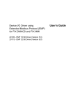
LCD DISPLAY
The charger/rectifier is supplied with a standard two-line high visibility back-lit LCD display.
M103 rev. 17
6
KEYPAD
The keypad is used for programming the charger/rectifier, resetting the alarms, etc. Four long life membrane
switches are used as the buttons F1, F2, F3 and F4.
DISPLAY UNIT
The first higher row of the LCD displays the information such as the adjustable values, number of relays, alarm
ON/OFF status and voltage level. The keys’ functions are displayed lower, depending of the menu context.
When an alarm is activated, an exact failure message appears and the red LED starts blinking. In case of the
multiple alarms, all the warning messages are shown sequentially and repeatedly.
The green LED is the AC power ON indicator.
All parameters can be saved individually.
If the keypad has been inactive for 5 minutes, the LCD power save feature shuts down backlighting of the display
unit. The charger/rectifier returns to the main menu upon wake-up.
The display accuracy is ± 0.5%, ± 1 digit
M103 rev. 17
7
KEYPAD AND CONTROL MENU
KEYPAD BUTTON FUNCTIONS
BUTTON
F1
Display
ACTION
OK
“Ok” or “Set”
NOTE
Enter the displayed sub-menu
or Set a sub-function’s value
F2
Step Down
Go down to next level
F3
Step Up
Go up to the previous selection
F4
Return
Exit
Return to the last selection
MAIN MENU
Use F2 or F3 keys to choose a menu or to go to/return from a sub-menu or to change a value. Use F1 to enter a
menu/sub-menu or to memorize a setting. Use F4 to exit/return to the last selection.
ACCESSING MENU VIA KEYPAD. QUICK OVERVIEW
On powering the unit up the following reading appears on the screen (example):
Error! No topic specified.
At this point, pressing any key once will bring the menu screen:
MODE Flt
Ok
F1
F2
Eq
Exit
F3
F4
Pressing F1 (Ok) gives the access to Float / Equalize menu. Pressing F4(Exit) steps back to the menu.
The other functions can be reached from the menu by pressing F2(Æ):
Error! No topic specified.
One more touch of F2 (Æ) key will bring the first function “Reset Alarm ?” (visible only in case of an alarm):
Error! No topic specified.
Continuous pressing of F2 (Æ) will make the screen to go through the following functions:
Error! No topic specified.
Error! No topic specified.
Error! No topic specified.
Error! No topic specified.
Pressing F1 (Ok) at any of these steps will bring up the corresponding sub-menu.
Pressing F3 (Å) makes the screen come back to the previous menu, one step at a time:
Error! No topic specified.
The majority of the functions have a few sub-functions. The sub-functions’ tree structure is explained in the
following paragraph.
MENU STRUCTURE OVERVIEW
M103 rev. 17
8
NOTE: DEPENDING ON A PARTICULAR PER-ORDER CONFIGURATION SOME OF THE MENUS BELOW
MAY NOT BE APPLICABLE.
WARNING: MODIFICATIONS OF THE FACTORY PRESETS MIGHT AFFECT THE OPERATION OF THE
CHARGER/RECTIFIER, AND SHOULD BE DONE BY QUALIFIED AND TRAINED PERSONNEL ONLY,
OTHERWISE THE WARRANTY IS VOID.
M103 rev. 17
9
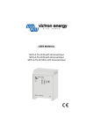
EQUALIZE
Eq
Exit
MODE Flt
Ok
F1
F1
F2
Float
Eq
Exit
F2
F3
F4
Float
Eq
Exit
F2
F3
F4
Float
F1
F3
F4
Float
Eq
Exit
F2
F3
F4
Float
Eq
Exit
F2
F3
F4
F1
Equalize
FUNCTION or ACTION
F1
MEANING
Float
Sets Float mode
Equalize
Sets Equalize mode
Exit
Returns to the main menu
M103 rev. 17
10
RESET ALARMS AND RELAYS
NOTE: available in case of an alarm only
Eq
Exit
MODE Flt
Ok
F1
F2
F3
F4
Reset Alarm
Ok
F1
Reset Relay
Yes
F1
F2
F3
F2
F1
F2
F3
F3
F4
No
Reset Relay
Yes
F4
F1
With resetting the alarm relays
Reset Alarm Msg
Yes
?
Exit
No
F3
F2
Without resetting the alarm relays
No
Reset Alarm Msg
Yes
F4
F1
With resetting the alarm messages
F4
F2
No
F3
F4
Without resetting the alarm
DISPLAY
FUNCTION or ACTION
MEANING
Reset relays
Yes
Resets all the alarm relays
No
Goes back to Reset alarm menu
Yes
Clears all alarm messages
No
Goes back to Reset alarm menu
Reset Alarm msg
M103 rev. 17
11
READINGS
Readings?
Ok
F1
F2
Exit
F3
Frequency
Ok
F1
F2
Exit
F3
Frequency
Ok
F1
F2
F4
F4
59.99Hz
Exit
F3
F4
FUNCTION or ACTION
MEANING
Access to display AC frequency
OK
RELAY TEST
Relay Test?
Ok
F1
F2
Exit
F3
Relay Test?
Yes
F1
Relay Test
F2
F4
No
F3
F4
Yes
Tests all relays
No
Goes back one level
M103 rev. 17
12
LCD Contrast
Contrast LCD
Ok
F1
F2
Exit
F3
Contrast LCD
Set
F1
F2
Contrast LCD
+
F1
F2
F4
Exit
F3
F4
-
Exit
F3
F4
FUNCTION or ACTION
MEANING
OK
Access to LCD Contrast control menu
Set
Access to LCD Contrast control
+
Increases LCD Contrast
–
Decreases LCD Contrast
M103 rev. 17
13
TROUBLESHOOTING
Warning: only qualified personnel should attempt to service the charger/rectifier. The DC and AC sources must
be disconnected and de-energized before replacing any component.
Fault
No output
Recommendation
-
AC breaker open: verify that the AC breaker is closed ("ON")
-
AC input failure: verify that the AC supply is there and the voltage and frequency are correct
-
DC fuse blown: check out the DC output fuse
-
Bad connection: verify the output and the input connections
-
Control board failure: Verify the board condition, and replace if needed
-
SCR module burnt out: replace the thyristor module(s)
-
High Voltage Shutdown has happened if this option is activated: 1. Investigate the reason. 2. Turn off the AC and
DC breakers for 5 minutes, and then restart
DC fuse or
-
Free wheeling diode failure: check the diode for a short circuit, replace if needed
breaker
-
Control board failure: Verify the board condition, and replace if needed
blows/trips
-
Overload: verify the load and the batteries
AC breaker trips
-
Check for short circuit(s)
-
SCR, Diode or Control board failure: check the components, and replace the defective ones if needed
-
Float, Equalize and/or High Voltage Alarm adjustments are affected. Refer to the adjustment procedures to reset
-
Control board failure: Verify the board condition, and replace if needed
-
Charger/rectifier overload: Check if the charger/rectifier is in Current Limit mode. Check the load for problems.
-
Input voltage is beyond the limits: Check the input voltage. Under sizing the AC wires can be the cause
-
Float, Equalize and/or Low Voltage Alarm adjustments are affected. Refer to the adjustment procedures to reset
-
Control board failure: Verify the board condition, and replace if needed
-
Defective filter capacitor: disconnect the capacitor to observe if there is any change in the output voltage. If so,
High DC voltage
Low volts alarm
replace the capacitor
High ripple
-
AC supply voltage is too high: Read the input voltage and rectify the situation
voltage
-
Defective filter capacitor: disconnect the capacitor to observe if there is any change in the output voltage. If so,
replace the capacitor
abnormal noise
-
SCR, Diode or Control board failure: check the components, and replace the defective ones if needed
-
Check the thyristor(s) and magnetics
-
Replace control board
If a trouble persists, contact our service department, please.
M103 rev. 17
14
REGULAR PREVENTIVE MAINTENANCE
Certain regular maintenance operations are required to insure that the charger/rectifier and the rest of the system
function properly.
Maintenance operation
Frequency
B
Measure and record the voltage
across each battery cell and across
the entire battery bank.
monthly
B
Verify and record the electrolyte level
in each battery cell. If necessary top off
with distilled water.
monthly
B
Verify and record the specific gravity
of electrolyte in each battery cell
monthly
C
Verify the charger/rectifier performance.
B, C
Remove accumulated dust,
especially around ventilation openings
yearly
B, C
Visually verify the conditions of all
components
yearly
B, C
Verify all connections. If necessary
tighten to recommended torque according
to manufacturers’ specifications
yearly
B
Clean and re-grease all battery
connections
yearly
B
Wash batteries using distilled water only
yearly
B = battery
monthly
C = charger/rectifier
For systems supplied with lead acid batteries, a partial discharge of the batteries to verify battery and
charger/rectifier performance is recommended on the annual basis.
For systems supplied with nickel-cadmium batteries a complete discharge and decommissioning charge on a biannual basis is recommended.
M103 rev. 17
15
CONTROL BOARD (PC) - ADJUSTMENT PROCEDURE
REQUIRED TOOLS
1. DC voltmeter, DC ammeter or multimeter.
2. DC or a dummy load.
Use the test report of the unit ( included in the user's manual) to have the following data available
1. DC output float voltage Vf
2. DC output equalize voltage (if required) Ve
3. DC output maximum current im
METHOD
(for your specific Ni-Cd or lead acid please use the information provided by the battery supplier)
You need
•
•
•
Float voltage/cell: Vf/C
Equalize voltage/cell: Ve/C
Number of cells
CURRENT LIMIT
Adjust the current limit to the test report value Imax
A
Float voltage Vf
Equalize voltage Ve
Auto equalize level Vae (if activated)
Maximum charging current Imax
B
Number of cells x Vf/C= Vf
Number of cells x Ve/C=Ve
Vf x 0,85
Imax
NOTE: All settings must be readjusted to the battery manufacturer specifications
PROCEDURE
1. Switch the AC breaker off.
2. Switch the DC breaker off (if provided).
3. Disconnect the batteries from the charger/rectifier.
4. Connect a resistive load
5. Connect a DC voltmeter across the DC output terminal (see the wiring diagram)
6. Switch the AC breaker on.
Use Æ or Å keys to access Control sub-menu. SET to enter menu. EXIT to return to previous menu
DISPLAY
Press
ACTION
By default
Value
Float
+ or -
To adjust Float Voltage
Vf (V)
I LIM
+ or -
To adjust Current Limit
Imax (A)
Eq
SET
Toggles On/Off Equalize Voltage
On
+ or -
To adjust Equalize Voltage
Veq (V)
+ or -
To adjust Equalize Time
T eq
M103 rev. 17
16
L VEQ
+ or -
To adjust Low Equalize Voltage
Vae (V)
TI LIM E
+ or -
Adjust Time/Current limit Equalize
5 min
AC Eq (if needed)
SET
Toggles AC Equalize On/Off
On
Tfloat (if needed)
+ or -
To adjust Float Timing
28 Days
ALARMS ADJUSTMENT PROCEDURE
REQUIRED TOOLS
1. DC voltmeter, DC ammeter or multimeter.
2. DC or a dummy load.
Use the test report of the unit ( included in the user's manual) to have the following data handy:
1. DC output float voltage Vf
2. DC output equalize voltage (if required) Ve
3. DC output maximum current im
DC OUT METHOD
For your specific Ni-Cd or lead acid please use the information provided by the battery supplier.
You need
•
•
•
Float voltage/cell: Vf/C
Equalize voltage/cell: Ve/C
Number of cells
A
Float voltage Vf
Equalize voltage Ve
High volts alarm Vh
Low volts alarm VL
Rectifier fail Vrf
Ground Ignd
B
Number of cells x Vf/C= Vf
Number of cells x Ve/C=Ve
1.05 x Veq
0.8 x Vf
0.80 x Vf
5 mA
NOTE: All settings must be readjusted as per the battery manufacturer’s specifications
PROCEDURE
1. Switch the AC breaker off.
2. Switch the DC breaker off (if provided).
3. Disconnect the batteries from the charger/rectifier.
4. Connect a resistive load
5. Connect a DC voltmeter across the DC output terminal (see the wiring diagram)
6. Switch the AC breaker on.
M103 rev. 17
17
Use Æ or Å keys to access Level 2 sub-menu. SET to enter menu. EXIT to return to previous menu
DISPLAY
Press
ACTION
Default Value
Talarm
+ or –
To adjust Alarm Timing
10 sec
HVAL
+ or –
To adjust High Voltage Alarm level
Vh
NEXT
Goes to Relays selection/toggle menu
NEXT, On/Off
Toggles High Voltage Alarm On/Off
On
OFF, + or –
Selects relays number (1 to 7)
No. 2
+ or –
To adjust Low Voltage alarm level (V)
VL
NEXT
Goes to Relays selection/toggle menu
NEXT, On/Off
Toggles Low Voltage Alarm On/Off
On
OFF, + or –
Selects relays number (1 to 7)
No.3
+ or –
To adjust Negative Ground Fault Alarm
5 mA
LVAL
GNDF–
level
NEXT
Goes to Relays selection/toggle menu
On
NEXT, On/Off
Toggles Negative Ground Fault
No. 4
OFF, + or –
Selects relays number (1 to 7)
+ or –
To adjust Positive Ground Fault Alarm
level
GNDF+
AC Fail
Rectifier Fail
5 mA
NEXT
Goes to Relays selection/toggle menu
NEXT, On/Off
Toggles Positive Ground Fault
On
OFF, + or –
Selects relays number (1 to 7)
No. 4
+ or –
Selects relays number (1 to 7)
NEXT
Goes to Relays selection/toggle menu
NEXT, On/Off
Toggles AC Failure Alarm On/Off
On
OFF, + or –
Selects relays number (1 to 7)
No.5
+ or –
Selects relays number (1 to 7)
Vrf
NEXT
Goes to Relays selection/toggle menu
NEXT, On/Off
Toggles On/Off AC Failure Alarm
On
OFF, + or –
Selects relays number (1 to 7)
No.1
M103 rev. 17
18
TYPICAL POWER TRANSFORMER CONFIGURATION
By default, all standard chargers with a multitap power transformer are configured for 240 Vac input, unless
specified otherwise at the time of purchasing. Before you wire ac power to your charger, check the wiring of the
main transformer T1, to be sure it is configured for your ac input voltage.
Depending on the output power rating, the chargers can accept an input voltage of 120, 208, 230, 240 or 480
Vac. The factory wiring is for 240 Vac by default. By reconfiguring T1, the chargers can accept an input voltage of
120, 208, 230 or 240 Vac.
NOTE: The chargers built for 480 Vac input cannot be reconfigured for a lower AC input voltage, and such
attempts shall not be made even if there are some other taps available for a lower AC input voltage. Such
attempts void the warranty and in no way the manufacturer and/or the distributor/reseller may be held
responsible for any consecutive damage(s).
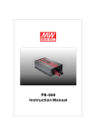
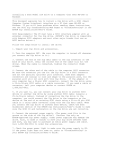
The control card power supply cable is always attached to 120 Vac taps, and MUST stay always attached to
them. In case, if 120 Vac taps are not available directly off the power transformer, the control card power supply
cable is attached to 240 Vac taps, and the corresponding control board jumpers SW1 are reconfigured as well. If
neither 120 nor 240 Vac taps are available directly off the power transformer, a small T2 control transformer (with
120 Vac secondary) is used to power up the control board and possibly some other equipment.
Figure 1.
Control board SW1 jumper configurations for 120/240 Vac
Should you require reconfiguring a charger for a different input voltage, the following instructions shall be
executed:
1. Comply with the “IMPORTANT SAFETY INSTRUCTIONS” on page 3 of this manual prior to starting
servicing the unit.
2. Ensure that all voltages are disconnected and secured from an accidental reconnection.
3. Ensure that the terminals are well connected.
4. Ensure that the stud terminals are tight.
5. Check your work after completion.
6. See the manual appendix for additional information if needed.
Verify that no voltage is present by using a voltmeter at the input and output terminals.
M103 rev. 17
19
NOTE: Turning off the AC and DC circuit breakers on the charger does not eliminate live voltages inside
the enclosure.
After verifying that all voltages within the enclosure are de-energized and locked out, reconfigure T1 as shown on
the drawings and in the tables on the following pages. Always ensure that your control board SW1 jumper
configuration corresponds to that of the power cable J5-1 attachment, after reconfiguring the charger input
voltage.
M103 rev. 17
20
WARRANTY
Electrical / Electronic Products Warranty
The Manufacturer Warrants to the original user only that its equipment is free from defects in factory
workmanship and materials, such warranty being conditional upon the product having been installed,
commissioned, operated and maintained by qualified personnel and according to manufacturer
instructions.
Our liability is limited to repairing or replacing without charge at our factory any product or
component which, at user's expense, has been returned to our plant or authorized service center
within 18 months from the date of shipping or 1 year from date of commissioning, whichever occurs
first. The manufacturer repair or replacement of any defective product shall constitute fulfillment of
his obligations.
This warranty applies to manufacturer products which are shown by the purchaser to have been
originally defective and shall not apply to products which must be repaired or replaced due to normal
wear, misuse, negligence, wreckage, accident, any Act Of God or to products which have been
repaired or altered outside of seller's factory or one of its authorized service centers unless
authorized solely by the manufacturer.
The manufacturer shall not be liable for loss, damage, or expense, consequential or otherwise from
the use of its products or from any other cause.
This warranty supersedes and is given in place of all other warranties expressed or implied or
conditions whether statutory or otherwise as to quality and fitness for any purpose for which the
products are supplied. No person, agent or dealer is authorized to give any warranty on behalf of
manufacturer or to assume for seller any other liability in connection with any of its products unless
made in writing and signed by an officer of the manufacturer.
M103 rev. 17
21
ANNEXES
Mechanical Drawings
Electric diagram
Optional features
Part list
Test report
M103 rev. 17
22