1
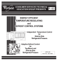
A COMPLETE GUIDE TO OPERATION,
TROUBLESHOOTING AND SERVICE PROCEDURES
©2005 DRY AIR SYSTEMS Group 457364 (04/05)
The JP Dryer System
An effective solution to the problems of oil, water vapor and contaminants in compressed air systems.
Compressed air, a reliable source of pneumatic power in many applications, is adversely affected by oil, dirt, and
water. In a variety of applications from automotive paint booths to concrete plants to general manufacturing
facilities, moisture, particulate, and oil in compressed air lines contribute to lower productivity, higher operating
costs and increased maintenance.
If your applications depend on a reliable supply of clean, dry air, you may already have explored the options
available to you and discovered they are often unreliable, cost-prohibitive, or maintenance intensive.
The DRY AIR SYSTEMS Oil Separator-Filter-Dryer (JP) is a better solution. Not just another air dryer, this ingenious
3-in-1 duplex system typically requires less than 10% of air for regeneration and achieves a -40º F pressure dew point
for flow rates of up to 40 CFM. The JP’s patent pending modular design allows for expansion to accommodate
changes in air system requirements or flow rates exceeding 40 CFM.
What’s more, preventative maintenance is straightforward, with accessible valves and two spin on desiccant
cartridges. The molecular sieve (desiccant) and filters are housed within the spin on/off cartridges. Typically,
these may be serviced within minutes. If required, the valves may be removed and reinstalled without
disassembling the unit.
Commonly used in conjunction with large air compressors and systems, the JP dryer system also may be mounted on
small air compressors or at point of use such as spray booths or workstations.
JP Dryer System
The JP is a practical, reliable, cost effective solution, insuring quality compressed air—free of oil, contaminants,
and water.
¾
¾
¾
¾
Compact size allows for easy installation and maintenance
Three-in-One system removes oil, contaminates, and moisture
Straightforward design provides reliable, long-term operation
Typically requires less than 10% regeneration air while others draw up to 20%
1
TABLE OF CONTENTS
Introduction. . . . . . . . . . . . . . . . 3
Chapter1: Installation. . . . . . . . . . . 4
• JP Installation and Service Instructions
• Basic Mounting Guidelines
• Mounting JP Base Assembly
• Connecting Air Lines
• Installing Desiccant Cartridges &
• Mufflers
• Micro Logic Timer (MLT) Electrical
• Connection
• Start-up/Check
• JP Operation/Cycle
• Schematic Drawings
• Service Parts Schematic
Chapter2: JP Lists . . . . . . . . . . . . 7
• JP Dryer Parts List
• Service Parts Identification
• Major Service Kit
• Minor Service Kit
Chapter 3: Trouble-shooting . . . . . . . . 8
• JP Air Dryer Operation/Cycle
• Problems, Causes, Remedies
Chapter 4: Service Procedures . . . . . . . 10
• JP Air Drying System
Warranty
. . . . . . . . . . . . . . . . . 13
2
JP INSTALLATION AND SERVICE INSTRUCTIONS
WARNING: BEFORE PROCEEDING WITH INSTALLATION READ AND OBSERVE THE FOLLOWING
SAFETY PRECAUTIONS:
1. Read entire instruction sheet before beginning installation or servicing of JP.
2. Never connect or disconnect a pipe/line containing air pressure or remove a component, fitting or pipe
plug unless you are certain all air pressure has been relieved.
3. Always wear proper eye protection when installing or servicing JP.
4. Never look directly into ports of JP.
5. Never exceed recommended working air pressure of 175 psig.
6. Never attempt to install or service JP until you read and understand all recommended procedures.
7. Use only proper tools and observe all precautions pertaining to the use of those tools.
BASIC MOUNTING GUIDELINES
1. The JP must be mounted with the exhaust ports positioned downward (ref. Figure 1, Pg. 5).
2. Power source: 110-120 Volt AC (grounded) surge protected (recommended) electric receptacle required
for operation of JP.
3. Mount JP down stream of air compressor reservoir (ref. Figure 1, Pg 5).
4. The JP should be mounted in a location with sufficient space around it to facilitate service and to
provide visual access for periodic inspection. Allow at least a two (2.00) -inch clearance above desiccant
cartridges for service (ref. Figure 2, Pg. 5).
5. Consider installing a series of lines and shut-off valves in conjunction with installation of the JP to
provide a by-pass system of the JP. Doing so will provide ability to maintain operation of air system
when servicing JP.
MOUNTING JP BASE ASSEMBLY
1. After determining proper location for JP as instructed in “Basic Mounting Guidelines” section, refer to
Figure 2, Pg. 5 for mounting reference dimensions.
NOTE: The JP is available with either standard wall or optional universal mount bracket as shown
3
in Figure 2. Either type bracket may be inverted from position shown in Figure 2, Pg. 7 to facilitate
mounting.
2. Mount base assembly at chosen location prior to installing desiccant cartridges. Make sure there will be a
minimum two (2.00) -inch clearance above desiccant cartridges for future service.
3. Refer to Figure 2, Pg 5 for mounting hole locations, and attach JP to mounting location with a minimum of two
(2) 3/8” bolts.
CONNECTING AIR LINES
1. Connect high-pressure airline (175 psig max.) to JP inlet port (ref. Figure 1, Pg 5).
2. Connect JP outlet port to system airline (ref. Figure 1, Pg 5).
NOTE: Use thread sealant on airline fittings to prevent air leaks.
INSTALLING DESICCANT CARTRIDGES & MUFFLERS
1. After base assembly is mounted, install both desiccant cartridges to base assembly as follows:
a. Install o-ring into groove of each center thread adaptor in base assembly.
b. Lubricate both o-rings and threads.
c. Lubricate contact surface of flat gasket located in cartridge plate.
d. Start cartridge onto thread adaptor being careful not to cross thread. Turn cartridge clockwise until flat
gasket contacts casting surface. After gasket contact, turn cartridge only 1/2 to 3/4 additional turns.
NOTE: Do not over-tighten cartridge or future removal will be extremely difficult.
2. Install muffler into each exhaust port of JP.
MICRO LOGIC TIMER (MLT) ELECTRICAL CONNECTION
1. Plug-in MLT power cord to 110-120 Volt AC grounded receptacle (surge protected recommended.
NOTE: The MLT device is polarity sensitive. MLT will not operate if power (+) and neutral (-) leads
are switched.
START-UP/CHECK
1. Ensure that all airline fittings are properly connected.
2. Pressurize system.
3. Check airline fittings for leaks and repair leaks.
4. Observe operation of JP for proper function as described in JP OPERATION/CYCLE section. (listed below)
JP OPERATION/CYCLE
1. The Micro Logic Timer (MLT) controls drying and regeneration cycles of the JP by energizing and deenergizing the “air control valve” of JP at 2-minute intervals. An indicator light on MLT will be on during
energized cycle and off during the de-energized cycle.
2. The JP’s “air control valve” controls airflow direction through the JP. During operation, one desiccant cartridge
is drying air and the other cartridge is being regenerated.
3. During operation there will be a light flow of air from ONE exhaust port (muffler) of JP. This is normal,
regeneration; airflow and the airflow will alternate every 2 minutes from one exhaust port to the other in
4
Figure 1: Air Connection Schematic
Figure 2: JP Unit Dimensions
5
SERVICE PARTS SCHEMATIC
*H &I – 2 each in service kits 619700 and 619702
6
JP DRYER PARTS LIST
JP Air Drying System – Complete Models
Air Flow Capacity
640100 W/Universal Mounting Bracket
640200 W/Wall Mounting Bracket
Up to 40 SCFM
640300 W/O mounting bracket or W/O Oil Separators
640400 W/Wall Mounting Bracket Duplex System
*40 – 80 SCFM
* Contact customer Service @ 1-314-344-1114 for applications greater than 80 CFM Service Parts Identification
Service Parts Identification
BOLD SKU SUGGEST SERVICE STOCK
A
* 619704
Desiccant Cartridge Kit
B
C
619765
619715
D
Use * 619702
E
F
619755
619760
Air Control Valve
Oil Separator Kit
G
619740
Safety Valve (200 PSI)
H
I
Use * 619702
Use * 619702
J
K
L
M
619770
619750
619990
619995
Cartridge Stud
Regeneration Valve Kit
Note: Two valves per dryer, one on either side.
Outlet Check Valve - Not sold separately
Purge Valve - Not sold separately
Inlet Check Valve - Not sold separately
Muffler
120 Volt AC Heater Kit (Optional)
Wall Mounting Bracket
Universal Mounting Bracket
Major Service Kit
A
D
H
I
619700
* Supplied also in 619700
2 - Desiccant Cartridges
1 - Outlet Check Valve
2 - Purge Valves
2 - Inlet Check Valves
TROUBLE-SHOOTING
JP AIR DRYER SYSTEM
JP AIR DRYER OPERATION/CYCLE (All Models)
1.
The Micro Logic Timer (MLT) controls drying and regeneration cycles MALFUNCTIONING of the JP Air Drying System by
energizing and de-energizing the Air SYSTEM PRESSURE SETTING Control Valve at two (2) minute intervals. An indicator
light on MLT will be “on” during energized cycle and “off” during the de-energized cycle.
2.
The JP’s Air Control Valve controls air flow direction through the JP during operation. During operation one JP cartridge is
drying air while the other cartridge is being regenerated.
3.
During operation there will be a light flow of air from ONE exhaust port (muffler) of JP. This is normal regeneration airflow. The
airflow will alternate (every 2-minutes) from one exhaust port (muffler) to the other in conjunction with the MLT cycles. When
the JP cycle alternates there will be a momentary burst of air from one of the JP exhaust ports (muffler). This airburst is normal
and will occur each time JP cycle alternates.
PROBLEM: HEAVY AIR FLOW FROM ONE OR BOTH OF JP EXHAUST PORTS (MUFFLERS)
NOTE: ALTERNATING “LIGHT” AIR FLOW FROM EXHAUST PORT (MUFFLER) IS NORMAL AS THIS REPRESENTS THE
REGENERATION CYCLE
POSSIBLE CAUSE
REMEDY
WORN PURGE VALVE OR
DIRT/FOREIGN
MATERIAL IS
STUCK IN THE PURGE
VALVE
WORN INLET CHECK
VALVE
CLEAN CAVITIES AND REPLACE
PURGE VALVE ASSEMBLY
ITEM “H” (REF. Pg. 6) SERVICE KIT #619702
CLEAN CAVITY AND REPLACE VALVE ASSEMBLY
ITEM “I” (REF. PG. 6) SERVICE KIT #619702
PROBLEM: SAFETY VALVE OPENS
POSSIBLE CAUSE
REMEDY
SAFETY VALVE
MALFUNCTIONING
REPLACE SAFETY
VALVE #619740-200 PSI
SYSTEM PRESSURE
SETTING EXCEEDS
SAFTEY VALVE SETTING
(200 PSI)
ITEM “G” (REF. Pg 6) SERVICE KIT #619740
REDUCE SYSTEM OPERATING AIR PRESSURE
8
PROBLEM: WATER IN AIR SYSTEM
POSSIBLE CAUSE
REMEDY
DESICCANT IS
CONTAMINATED
MICRO LOGIC TIMER
(MLT)
MALFUNCTIONING
REPLACE DESICCANT CARTRIDGES ITEM “A” (REF. Pg. 6) SERVICE KIT #619700 OR
#619704
CONTACT DRY AIR SYSTEMS CUSTOMER SERVICE (1-314-344-1114) OR LOCAL
DISTRIBUTOR REPRESENTATIVE
AIR CONTROL VALVE
MALFUNCTION
MALFUNCTIONING
REGENERATION
VALVE(S)
AIR LINE (TUBING)
CONNECTING AIR
CONTROL VALVE AND
VALVE HOUSING
AND/OR MANIFOLD
DAMAGED OR MISSING
EXHAUST PORTS IN
PURGE VALVE AND
VALVE HOUSING NOT
ALIGNED
COMPRESSED AIR
USAGE EXCEEDS
DRYING CAPACITY OF JP
WORN PURGE VALVE
REPLACE AIR CONTROL VALVE ITEM “E” (REF. Pg. 6) SERVICE KIT #619755
REPLACE REGENERATION VALVE(S) ITEM “C” (REF. Pg. 6) SERVICE KIT #619715
REPAIR/REPLACE AIRLINE(S) (TUBING) CHECK FOR LEAKS AT FITTING THREADS
ALIGN EXHAUST PORTS IN PURGE VALVE AND VALVE HOUSING
CONTACT DRY AIR SYSTEMS CUSTOMER SERVICE (1-314-344-1114)
REPLACE PURGE VALVE ASSEMBLY
ITEM “H” (REF. Pg. 6) SERVICE KIT #619700 OR #619702
PROBLEM: JP’S CYCLES WILL NOT ALTERNATE EVERY TWO MINUTES POSSIBLE CAUSE REMEDY
POSSIBLE CAUSE
MICRO LOGIC TIMER
(MLT)
MALFUNCTIONING
AIR CONTROL VALVE
MALFUNCTION
AIR LINE (TUBING)
CONNECTING AIR
CONTROL VALVE AND
VALVE HOUSING
AND/OR MANIFOLD
DAMAGED OR MISSING
REMEDY
CONTACT DRY AIR SYSTEMS CUSTOMER SERVICE (314-344-1114)
REPLACE AIR CONTROL VALVE #619755
ITEM “E” (REF. Pg. 6) SERVICE KIT #619755
REPAIR/REPLACE AIRLINE(S) (TUBING)
PROBLEM: JP’S INADEQUATE SYSTEM AIR VOLUME AFTER JP AIR DRYER
POSSIBLE PROBLEM
REMEDY
AIR FLOW RESTRICTION
(NEW INSTALLATION)
DESICCANT
CARTRIDGES/ OIL
SEPARATORS
RESTRICTED
CONTACT DRY AIR SYSTEMS CUSTOMER SERVICE (1-314-344-1114)
REPLACE DESICCANT CARTRIDGES ITEM “A” (REF. Pg. 6) SERVICE KIT #619700 OR
#619704 REPLACE OIL SEPARATORS ITEM “F” (REF. Pg. 6) SERVICE KIT #619760
9
SERVICE PROCEDURES
JP AIR DRYING SYSTEM
(Items A, C, D, E, F, H, I, K)
WARNING: BEFORE SERVICING JP DRYING SYSTEM, READ AND FOLLOW SAFETY
PRECAUTIONS FOUND ON PAGE 3. REVIEW DESCRIPTION OF JP AIR
DRYEROPERATION/CYCLE, LOCATED 0N Pg. 8.
Item “A” Desiccant Cartridges - #619704 Cartridges only or Major Service Kit #619700
1.
2.
3.
4.
5.
6.
7.
Relieve all system air pressure.
Using a strap wrench, turn the desiccant cartridge counterclockwise and remove it. Discard.
Remove and discard O-ring from adapter plate stud.
Clean top surface of adapter plate and threaded stud.
NOTE: If there is excessive oil present, compressor and/or oil separator (Kit #619760) require servicing.
Using grease supplied, apply a light coating on o-ring. Install o-ring on stud.
Apply a generous coat of grease on the new desiccant cartridge gasket surface.
Thread new cartridge onto stud turning clockwise. When gasket contacts adapter plate, tighten cartridge 1/2 to 3/4 turns.
DO NOT OVER-TIGHTEN!
Item “C” Regeneration Valves - #619715
Note: A light flow of air from exhaust port (muffler) during operation is normal regeneration airflow.
1.
2.
3.
4.
5.
6.
7.
8.
9.
10.
11.
12.
Relieve all system air pressure.
Disconnect airline from outlet port of air dryer.
Remove eight (8) socket head bolts fastening manifold to adaptor castings.
Remove manifold from adaptor castings.
Remove and discard o-rings, springs and regeneration valves.
Clean valve cavities in adaptor castings.
Position new valve spindles into cavities with spring pockets out.
Position springs into valves.
Lubricate new o-rings and install onto manifold bosses.
Position manifold onto adaptor castings ensuring O-rings are properly positioned in bores.
Install eight (8) socket head bolts and tighten to 50-60 in. lbs.
Reconnect airline to outlet port.
Item “D” Outlet Check Valve #619700 Major Service Kits or #619702 Minor Service Kit
1.
2.
3.
4.
5.
Relieve all system air pressure.
Disconnect airline from dryer outlet port.
Remove check valve nut.
Remove and discard o-ring, spring, spindle, and ball.
Clean nut and check valve cavity thoroughly.
NOTE: If there is excessive oil in the cavity, oil separator and desiccant cartridges require servicing.
6. Install new ball into cavity.
7. Install spindle, with spring pocket out, into cavity.
8. Place spring into spring pocket of spindle.
9. Apply a light coating of grease onto o-ring and place onto check valve nut.
10. Apply light coating of grease to nut threads. Install nut and tighten to 60 ft. Ibs.
11. Re-connect airline to outlet port.
10
Item “E” Air Control Valve - #619755
Note: Disconnect power from MLT.
•
With system pressurized, turn the brass screw located on air valve to the right -clockwise (screw slot will be in horizontal
position). If exhaust air burst does not occur, replace valve. If exhaust air burst does occur, turn screw back to original position
counter-clockwise (screw slot must be in vertical position for normal operation).
•
Failure of dryer to exhaust could also be due to malfunctioning MLT or purge valve. Refer to pages 10 and 16 for service of these
items.
1.
2.
3.
4.
Relieve all system air pressure.
Un-plug electrical connector from MLT Valve.
Remove three (3) airlines connected to fittings in air valve.
Remove plastic retaining nut holding MLT assembly to valve stem and remove MLT assembly from valve. Set aside nut and
MLT for re-assembly later.
5. Remove three (3) screws holding valve to manifold. Remove valve and discard.
6. Install three (3) new push connect airline fittings to open ports of new valve.
7. Attach valve to manifold with three (3) screws.
8. Tighten screws to 15-20 in. lb.
9. Re-connect airline from manifold to front port of air valve.
10. Re-connect two remaining airlines to back ports of valve.
11. Re-assemble MLT assembly to valve stem and secure with retaining nut (finger tight).
12. Reconnect electrical power.
Item “F” Oil Separators - #619760
1.
2.
3.
4.
5.
6.
7.
8.
9.
10.
11.
12.
13.
14.
15.
Relieve all system air pressure.
Disconnect heater lead wire from air dryer (if equipped)
Disconnect airline from dryer inlet port.
Remove two (2) desiccant cartridges (strap wrench may be necessary)
Remove (4) 3/8” Allen head bolts, located at top of adaptor casting, attaching adaptor castings to bottom valve housing.
Remove (12) 3/8” hex head bolts attaching bottom valve housing to adaptor castings.
Remove bottom valve housing assembly.
Remove two (2) oil separators and (4) gaskets from valve housing and discard.
Clean valve housing sump and inside of two (2) adaptor castings of all oil and contaminates.
Place one new gasket on each valve housing bolt flange.
Place new oil separators on top of first gaskets on valve housing (use two bolts to align components).
Place second new gasket on top of oil separators.
Reinstall valve housing/oil separator to adaptor castings.
Torque (16) bolts to 25-30 ft. Ibs.
Re-install two (2) desiccant cartridges.
NOTE: It is recommended to also install major service kit #619700 when excessive oil and contamination is present
16. Re-connect airline to air dryer inlet port.
17. Re-connect heater wire (if equipped).
Item “H” Purge Valves - #619700 Major Service Kit or #619702 Minor Service kit
Note: A light flow of air from ONE exhaust port (muffler) during operation is normal, regeneration air flow
1.
2.
3.
4.
5.
6.
7.
8.
9.
Relieve all system air pressure.
Remove two bolts that attach the purge valve retainer. Remove the retainer.
Remove the purge valve assembly and O-ring from the purge cavity and discard.
Clean the cavity thoroughly.
Remove the three (3) O-rings from retainer and discard.
Using lubricant supplied, lightly grease all three new O-rings.
Install on the retainer the two (2) larger O-rings then install the third (smaller) O-ring.
Apply a light coating of grease around the O-ring seat on valve assembly. Install the thin o-ring on the purge valve seat.
Insert valve assembly into cavity. Insure that hole in valve sleeves aligns over housing exhaust port (muffler). Use care not to
dislodge the O-ring from its seat.
WARNING:
If the JP purge valve port does not align with housing exhaust port, JP will not exhaust!
11
10. Install retainer to housing.
11. Apply a light coating of grease on the threads of the two retainer bolts.
12. Install two retainer bolts. Tighten to 10-15 ft. lb.
Item “I” Inlet Check Valves - #619700 Major Service Kit or #619702 Minor Service
kit
Note: A light flow of air from ONE exhaust port (muffler) during operation is normal, regeneration
air flow.
1.
2.
3.
4.
5.
6.
7.
Relieve all system air pressure.
Remove the two bolts that attach the inlet check valve retainer. Remove the retainer.
Remove the inlet check valve spindle from the inlet cavity and discard.
Clean the cavity thoroughly.
Remove the two (2) O-rings from retainer and discard.
Install two (2) large O-rings on the retainer.
Lubricate O-rings on check valve- spindle and install the spindle (small end first) into the inlet cavity. Make sure spindle is
completely engaged in cavity and slides freely.
8. Lubricate O-rings on seal retainer and re-install retainer.
9. Apply a light coating of grease on the threads of the two retainer bolts.
10. Install two retainer bolts. Tighten to 10-15 ft. lb.
Item “K” Heater Assembly (if equipped) - #619750
Note: Heater option to prevent inlet and purge valve freezing when JP is mounted where ambient air
temperatures may fall below 32° F (0° C).
1.
2.
3.
4.
5.
6.
7.
8.
9.
10.
11.
Disconnect heater lead wire.
Remove two screws attaching heater connector to casting.
Remove heater/thermostat assembly and discard.
Thoroughly clean entire heater/thermostat area.
Slide O-ring over heater and thermostat into position around connector flange.
Apply a light coating of anti-seize to the heater element and thermostat cavity.
Insert heater element into hole and twist slightly to spread anti-seize.
Place thermostat into position in cavity and ensure thermostat sits flat in cavity.
Place foam cube on top of thermostat and bring heater connector into position over cavity.
Secure heater connector using the (2) 8-32 x1/2” screws.
Reconnect heater.
12
WARNING: Proper selection of the products listed for sale in this catalog is essential to minimize the risk of any seal, bearing or other
product failure. Such failures can result in property damage or severe personal injury to operators of machinery, vehicles or to others. You
must carefully evaluate the particular application on or into which you intend to install the products. Products in this catalog require
installation by an experienced professional mechanic or qualified maintenance professional.
The product properties and operating parameters described in this catalogue are based upon tests conducted by DRY AIR SYSTEMS or
reported by others. DRY AIR SYSTEMS does not assume any responsibility for errors in the data published in this catalog. The life and
performance of the products ultimately depend on a number of factors. These include, for example, seal or bearing design, selection of
materials for their different properties, handling and installation, shaft surface or bore conditions, operating conditions, and the quantity,
quality and chemistry of lubricants. Severe environments can adversely affect product life or performance. For help in realizing longer seal
or bearing life, and optimal performance for your specific application, contact DRY AIR SYSTEMS at 1-314-344-1114.
LIMITED WARRANTY
DRY AIR SYSTEMS as the seller of the products contained in this catalog warrants to the first user/purchaser that the products sold by it,
when properly installed, will be free from defects in material and workmanship. DRY AIR SYSTEMS’s sole obligation and liability for
any defect found to exist in a product sold by DRY AIR SYSTEMS contrary to this warranty, and purchaser’s sole and exclusive remedy
for such defect, shall be limited to: (A) DRY AIR SYSTEMS furnishing without additional charge to purchaser, including transportation, a
replacement for any of the products sold by DRY AIR SYSTEMS which are found by DRY AIR SYSTEMS to be defective contrary to
this limited warranty, and (B) in the case of products which cannot be re-paired or replaced by DRY AIR SYSTEMS, DRY AIR
SYSTEMS shall credit or refund purchaser the purchase price paid therefore; provided, that DRY AIR SYSTEMS is advised in writing of
such product non-conformance within thirty (30) days of the date of discovery thereof, and that the non-conforming product is returned
f.o.b. to DRY AIR SYSTEMS’s designated warehouse promptly thereafter, but in any case not later than twelve (12) months from the date
of original shipment of the product to purchaser by DRY AIR SYSTEMS. In no event shall DRY AIR SYSTEMS be obligated under this
warranty or otherwise in any way whatsoever for normal wear and tear, or for any products sold by DRY AIR SYSTEMS which, after
delivery by DRY AIR SYSTEMS and in DRY AIR SYSTEMS’s sole determination, have been subjected to accident, abuse,
misapplication, improper or faulty repair or installation, improper or faulty maintenance or lubrication, any alteration or neglect, excessive
loading or other excessive operating conditions, or for defects caused by or resulting from purchaser’s specifications or designs or
otherwise caused by purchaser. TO THE FURTHEST EXTENT PERMITTED UNDER APPLICABLE LAW, DRY AIR SYSTEMS
DISCLAIMS LIABILITY, IN TORT OR CONTRACT, IN NEGLIGENCE, STRICT LIABILITY, OR OTHERWISE, FOR ANY
OTHER REMEDY OR DAMAGE, WHETHER DIRECT OR INDIRECT, INCIDENTAL OR CONSEQUENTIAL WITH RESPECT TO
ITS PERFORMANCE HEREUNDER, INCLUDING WITHOUT LIMITATION WITH RESPECT TO THE PRODUCTS SOLD OR
PROVIDED HEREUNDER BY DRY AIR SYSTEMS, AND ITS PROVISION OF ANY RELATED SERVICES. THIS EXPRESS
WARRANTY IS TO THE EXCLUSION OF ALL OTHER WARRANTIES, EXPRESS OR IMPLIED, INCLUDING WARRANTIES
OF MERCHANTABILITY OR FITNESS FOR A PARTICULAR PURPOSE. COSTS INCURRED FOR ROUTINE MAINTENANCE
ARE NOT COVERED BY THIS WARRANTY. Without limiting the generality of the foregoing disclaimer, DRY AIR SYSTEMS
specifically disclaims liability to purchaser for any loss, cost, or damage incurred as a result of equipment downtime, or loss of use or
availability of worksite, lost revenues or lost profits, or losses or liability arising, regardless of whether DRY AIR SYSTEMS is on notice
of the possibility of such damage or loss and did or could have anticipated same. No other person has been authorized by DRY AIR
SYSTEMS to undertake or make on behalf of DRY AIR SYSTEMS any further representation, warranty or guarantee in addition to or
contrary to DRY AIR SYSTEMS’s warranty made herein or contrary to the limitations and disclaimers provided herein. The exclusive
remedies provided in this limited warranty shall not be deemed to have failed of their essential purpose so long as DRY AIR SYSTEMS is
willing and able to perform to the extent and in the manner prescribed in this warranty.
INFORMATION: Inquiries can be directed to:
DRY AIR SYSTEMS Customer Service Department,
2655 Metro Boulevard
Maryland Heights, MO 63043
Or call 314-344-1114
Approved returns must be shipped freight prepaid and arrive right of Dry Air Systems
LIMITATION ON RETURNS: Any product that is not in conformance with purchaser’s description given in its order is returnable for credit or
replacement by Dry Air Systems, provided that Dry Air Systems is advised in writing by purchaser of such non-conformance within 30 days after
the product’s delivery to purchaser by Dry Air Systems, and only after written authorization therefore is given by Dry Air Systems. Approved
returns must be shipped freight prepaid and arrive in good, saleable condition to qualify for credit or replacement.
13
NOTES:
14