1
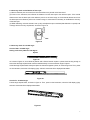
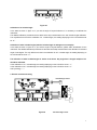
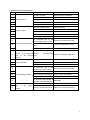
40-6065 Laser Digital Level
Service Manual
Content
1 Disassembly of instrument
1.1 Disassembly of keypad parts
1.2 Disassembly of horizontal-angle sensor parts
1.3 Disassembly of laser parts
1.4 Disassembly of ruler body parts
2. Accuracy check and calibration
2.1 Accuracy check of horizontal angle
2.2 Accuracy calibration of horizontal angle
2.3 Accuracy check and calibration of laser spot
2.4 Accuracy check of included angle
2.5 Accuracy calibration of included angle
3. Electric connection drawing
4. Solutions for usual malfunctions
40-6065 digital level is a kind of high accurate instrument. If there are any malfunctions, the instrument must be
serviced by authorized dealers of JOHNSON, or back to our company for servicing. When you repair this instrument,
you should conform to this manual. Any unprofessional persons are not allowed to disassemble the instrument or
perform any internal servicing by themselves.
Figure 1: appearance of the instrument
1. Disassembly of instrument
1.1 Disassembly of keypad parts
(1) Loosen the lock knob (1-9#), and turn the angle square board (1-8#) by a certain angle.
(2) Screw off the 6pcs crosshead sunk bolts M2.5×8(1-6#), take off the keypad parts, and then pull out the terminal
pins of power, horizontal-angle sensor as well as include angle sensor.
(3) Tear out the membrane (1-3#), unclench the 3pcs bolt covers (1-7#), and disassemble the 6pcs crosshead plate
bolts M2.5×10(1-4#).
(4) Pull out the 6pcs connecting staffs (1-2#), then disconnect the keypad (1-1#) and main circuit board (1-5#).
Figure 2
1-1 Keypad
1-4 Crosshead Plate Bolt M2.5×10
1-2 Connecting Staff
1-3 Membrane
1-7 Bolt Cover
1-5 Main Circuit Board
1-8 Angle Square Board
1-6 Crosshead Sunk Bolt M2.5×8
1-9 Lock Knob
2). Disassembly of horizontal-angle sensor parts
(1) Turn the angle square board by a certain angle.
(2) Disassemble the 3pcs crosshead sunk bolts M3×10(2-5#)and 2pcs crosshead sunk bolt M2.5×25(2-8#), pull
out the horizontal-angle sensor parts, and take off the press plate (2-3#).
(3) Disassemble the crosshead sunk tapping bolt ST2.5×10(2-6#), and unclench the cover board(2-2#);
(4) Disassemble the crosshead plate tapping bolt ST2.2×6.5(2-7#), then disconnect the sensor shell (2-1#)and the
sensor circuit board(2-4#)
Figure 3
2-1 Sensor Shell
2-2 Cover Board of Shell
2-4 Sensor Circuit Board
2-3 Press Plate
2-5 Crosshead Sunk Bolt M3×10
2-6 Crosshead Sunk Tapping Bolt ST2.5×10
2-7 Crosshead Plate Tapping Bolt ST2.2×6.5
2-8 Crosshead Sunk Bolt M2.5×25
1.3 Disassembly of laser parts
(1) Unclench the laser cover (3-3#)
(2) Turn the angle square board by a certain angle.
(3) Disassemble the 4pcs crosshead sunk bolts M2.5×6(3-5#), pull out the left-end cover parts, and disassemble the
power leading wire.
(4) Disassemble the 2pcs crosshead plate bolts M2×6(3-7#), and then disassemble the leading wire of light source,
i.e. disassemble the circuit board of light source (3-4#).
(5) Disassemble the 3pcs crosshead plate bolts M2.5×10(3-6#); then disconnect the left-end cover (3-2#) and the
light source parts (3-1#).
2
Figure 4
3-1 Light Source Parts
3-4 Light Source Circuit Board
3-7 Crosshead Plate Bolt M2×6
3-2 Left End Cover
3-5 Crosshead Sunk Bolt M2.5×6
3-3 Laser Cover
3-6 Crosshead Plate Bolt M2.5×10
1.4 Disassembly of ruler body parts
(1) Screw off the lock knob (4-4#), and disassemble the gasket φ6 (4-5#);
(2) Screw off the 2pcs crosshead plate bolts M2.5×8(4-11#), and disassemble the press plate (4-10#).
(3) Unclench the 2pcs protecting covers (4-1#) on both ends.
(4) Loosen the hexagon nut M6 (4-2#) and take off the gasket φ6 (4-3#), i.e. disconnect the mainframe parts (4-13#)
and the angle square board parts (4-12#)
(5) Disassemble the spacer (4-7#) from the mainframe, and unclench the including angle sensor (4-6#).
(6) Disassemble the electrical brush (4-9#) and the electrical brush seat (4-8#) from the angle square board.
Figure 5
4-1 Protecting Cover
4-5 Gasketφ6
4-2 Hexagon Nut M6
4-9 Electrical Brush
4-6 Included Angle Sensor
4-3 Gasketφ6
4-7 Spacer
4-4 Lock Knob
4-8 Electrical Brush Seat
4-13 Mainframe Parts
4-10 Press Plate
4-11 Crosshead Plate Bolt M2.5×8
4-12 Angle Square Board Parts
Note: All the above is the general dissembling course of 40-6065, and the assembling course of 40-6065 is
just the contrary. While repairing the instrument, it should take the disassembling level, procedure and
method according to the practical situation.
2.
Accuracy Check and Calibration
This function works only when the angle is in “UNLCOK” state.
3
2.1 Accuracy check of horizontal angle
Reference platform setting
As shown in figure 6, set a reference platform that has four flat and smooth sides and is 10m away from the wall.
Side A is horizontal, and its horizontal angle is 0°±10", Side C is parallel with and below side A, with the horizontal
angle is 0°±1°. Side B and side D are both perpendicular to side A, and the included angles between side A and side
B or side A and side D are both 90°±1°.
Wall
10m
Side A
Side B
Side D
Side C
Figure 6
0 degree check
(1) Put the instrument against the side A, as shown in figure 7. Install into the battery, and press the first key (from
left to right), i.e. ON/OFF key. Then, notice the LCD display (left), wait 10 seconds till the displayed data stable and
record the angle value.
Figure 7
(2) As shown in figure 8, rotate the instrument by 180 degree in A plane, wait 10 seconds again till the displayed data
stable then record the second angle value.
Figure 8
180 degree check
(1) As shown in figure 9, place the instrument against C plane and power on, notice the LCD display (left), wait 10
seconds till the displayed data stable and record the angle value.
Figure 9
(2) As shown in figure 10, rotate the instrument by 180 degree in C plane, wait 10 seconds again till the displayed
data stable then
record the second angle value.
Figure 10
90 degree check
(1) As shown in figure 11, place the instrument against B plane and power on, notice the LCD display (left), wait 10
seconds till the displayed data stable and record the angle value.
(2) As shown in figure 12, rotate the instrument by 180 degree in B plane, wait 10 seconds again till the displayed
data stable then record the second angle value.
4
Figure 11
Figure 12
Figure 13
Figure 14
270 degree check
(1) (1) As shown in figure 13, place the instrument against D plane and power on, notice the LCD display (left), wait
10 seconds till the displayed data stable and record the angle value.
(2) As shown in figure 14, rotate the instrument by 180 degree in D plane, wait 10 seconds again till the displayed
data stable then record the second angle value.
In the above four characteristic angle checks, if the difference between two angle values is over 0.1o, it is
necessary to recalibrate the instrument. After calibration, please check the four reference angles again till
they completely complies with the accuracy requirements
2.2 Accuracy calibration of horizontal angle
Please make calibration for the four angles 0°,90°,180°,270°simultaneously.
0 degree calibration
(1) Place the instrument according to the step 1 of 0 degree check (as shown in figure 7). Power on and press “Zero
calibration” key once, i.e. the third key (from left to right) with a “CAL “ sign. Then the LCD will display “-0-“ (figure 15)
Figure 15
(2) Wait ten seconds and then press again the “Zero calibration” key, the LCD will display “-1-“ (figure 16);
Figure 16
(3) Place the instrument according to the step 2 of 0 degree check (as shown in figure 8), wait 10 seconds and press
the “Zero calibration” key again, the LCD will display “-2-” (as shown in figure 17). After 10 seconds, the calibration is
completed and the LCD will display the current angle value. If it is failure to perform calibration, it means the
horizontal-angle sensor is defective. Please replace it.
Figure 17
The calibration methods of other reference angles are the same as the above. While calibrating, the placement of
instrument should refer to the placement as shown in their checks.
5
2.3 Accuracy check and calibration of laser spot
(1) Mark a reference point on the wall, and its horizontal accuracy should not be less than 5″.
(2) Power on the instrument, and observe the distance from the laser spot to the reference point. If the vertical
distance error from the laser spot to the reference point is out of ±3mm range, or the horizontal distance error from
the laser spot to the reference point is out of ±20mm range, it means that it is necessary to recalibrate the accuracy
of the laser spot.
(3) While calibrating, unclench the laser cover (3-3#), and adjust the 3pcs crosshead plate bolts M2.5×8(3-6#) until
it comply with the accuracy requirement, as shows in figure 18.
Bolt
Figure 18
2.4 Accuracy check of included angle
Check of 180°included angle
Setting a reference platform of 180 degree
A plane
Figure 19
As it shows in figure 19, set a reference platform with a flat and smooth A plane. A plane should be long enough to
ensure that the angle square board could be unfolded entirely but not exceed the range of A plane.
Unfold the angle square board entirely and place the instrument against A plane, as shows in figure 20. Then, power
on the instrument, notice the LCD display (right), and wait 10 seconds till the displayed data stable.
Figure 20
Check of 0°included angle
Fold the angle square board, as shown in figure 21. Then, power on the instrument, notice the LCD display (right),
and wait 10 seconds till the displayed data stable.
Figure 21
6
Check of other included angles
Reference platform setting
Baseboard
Figure 22
As shown in figure 22, set a reference baseboard and several reference blocking boards, which should be flat and
smooth enough. The included angle between two adjacent blocking boards is 10°. The included angle between the
baseboard and the blocking board could reach a maximum of 170° and a minimum of 10°.
Check of other included angles (take 30°included angle as an example)
Figure 23
Make the mainframe of the instrument against the baseboard. Turn the angle square board to the blocking board
that forms an included angle of 30 degree with the baseboard, as shown in figure 23. Power on the instrument,
notice the LCD display (right), and wait 10 seconds till the displayed data stable.
As for the included angle of 0°, 90° or 180°, if the accuracy of the display angle is out of ±0.1° range by
comparing with the reference angle, or as for other included angles, if the accuracy of the display angle is
out of ±0.2° range by comparing with the reference angle, then it is necessary to recalibrate the instrument.
After calibration, please check again until it complies with the accuracy requirement.
The check of other included angles is similar to the above, and it just needs to turn the angle square board
to the required blocking board. Any angle that is integral multiple of 10 degree should be checked.
2.5 Accuracy calibration of the included angle
Calibration of 180° included angle
(1) In the state as shown in figure 20, if you find the angle is beyond tolerance, it is necessary to recalibrate the
instrument.
(2) Tear out the membrane (1-3#)
(3) Power on the instrument, and press the switch 1, as shown in figure 24.
(4) Press the switch 2 or 3 again, adjust the reading displaying on LCD (right) until it displays “-18-”.
(5) Press the switch 1 again, and wait for 10 seconds.
(6) Finally, after the buzzer gives a beep, press the switch 4 and observe whether the included-angle reading
displaying on LCD (right) is correct or not. If it is not correct, please recalibrate the instrument until the reading
becomes correct. If the reading is still wrong after recalibrating, it means the included angle sensor is defective.
Please replace it.
7
Figure 24
Calibration of 0° included angle
In the state as shown in figure 21, if you find the angle is beyond tolerance, it is necessary to recalibrate the
instrument.
The detailed calibration procedures are the same as the step 2-6 described in the 180° included angle calibration.
The only difference is that in the calibration of 0°included angle,, the reading displaying on the LCD should be set
as “-0-”.
Calibration of other included angles (take the included angle of 30 degree as an example):
In the state as shown in figure 23, if you find the angle is beyond tolerance, please make recalibration for the
instrument. The detailed calibration procedures are the same as the step 2-6 described in the calibration for included
angle of 180 degree. The only difference is that in the calibration for 30°included angle, the reading displaying on
the LCD should be set as “-3-”.
The calibration of other included angles is similar to the above. Any angle that is integral multiple of 10°
should be calibrated.
In the calibration of 10°included angle, the reading displaying on the LCD will be set as “-1-”.
In the calibration of 20°included angle, the reading displaying on the LCD will be set as “-2-”.
And by analogy--------
202
106
106
103
103
103
103
Included angle sensor
3
104
104
104
104
104
103
103
103
103
106
184
4MHz
夹角
传感器
D
L
104
103
100P
105
105
1
104
104
0. 1U 0. 1U
184
153
3. Electric connection drawing
3
1
8
Figure 25
T
A
B
1
水平
角度
传感器
Horizontal-angle sensor
8
4. Solutions for usual malfunctions
No.
Malfunction phenomenon
Cause
Repair method
1
The battery is empty
Replace with the new batteries
2
The switch is loose contact
Replace the switch
The power line is cut off
Weld the leading wire
4
The connection line is loose.
Reinsert the connection line tightly
5
Defective 1# main circuit board
Replace the 1# main circuit board
6
The switch is loose contact
Replace the switch
The connection line is loose
Reinsert the connection line tightly
The connection line is cut off
Re-weld the connection line
9
Defective 1# main circuit board
Replace 1# main circuit board
10
Defective light source
Replace the light source
3
7
8
Failure to power on
No laser is output
The
11
12
No horizontal angle display Defective
line
of
the
horizontal-angle
sensor
13
Defective 1# main circuit board
After
14
connection
horizontal-angle sensor is loose
alignment,
is
still
Replace horizontal-sensor sensor
Replace the 1# main circuit board
the
accuracy of the horizontal Defective
angle
Reinsert the connection line tightly
horizontal-angle
beyond sensor
Replace the horizontal-angle sensor
tolerance
15
16
No sound indication
17
Replace the buzzer
Defective 1# main circuit board
Replace 1# main circuit board
connection
line
of
the
Reinsert the connection line tightly
Defective included angle sensor Replace the included angle sensor
No included angle display
21
Defective 1# main circuit board
Replace 1# main circuit board
Defective electrical brush
Replace the electrical brush
The electrical brush failures to
22
24
Defective buzzer
included angle sensor is loose
19
23
Replace the switch
The
18
20
The switch is loose contact
slide freely on the potentiometer
After alignment, the included Defective electrical brush
angle
tolerance
is
still
beyond
Reassembly
Replace the electrical brush
Defective included angle sensor Replace the included angle sensor
9