1
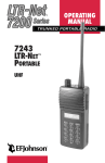
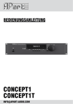
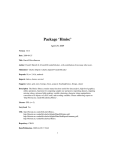
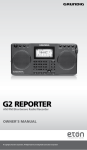
LTR-NET SERVICE MANUAL ADDENDUM, PART NO. 001-9800-600
REVISIONS
This revision describes changes and additions that
have occurred through March 2000 to the LTR-Net
Service Manual Addendum, Part No. 001-9800-600,
with a printing date of April 1999. Add this change
information to your copy of this manual.
SECTION 1
GENERAL INFORMATION UPDATES
CAUTION: When power is turned off with an LTRNet system selected, the transmitter automatically keys
briefly to transmit a de-registration message.
1.3 TRANSCEIVER IDENTIFICATION NUMBER
The illustrations on page 1-1 are reversed and the
type information in the identification number breakdown illustration has changed. The correct illustration
is as follows:
Identification Number Breakdown
Warranty
Revision Manufacture
Plant Number
Letter
Date
Model
From P.N.
98xx
x
A
10 9
A
1 = Low pwr LTR
2 = High pwr LTR
3 = High pwr Data MN
4 = Low pwr LTR-Net
5 = High pwr LTR-Net
6 = Low pwr Multi-Net
7 = High pwr Multi-Net
8 = Low pwr Data LTR
9 = High pwr Data LTR
0 = Low pwr Data MNet
Last Digit of Year
Week No. of Year
NOTE: Low power = 25W UHF,
15W 800/900 MHz;
High power = 40W UHF,
30W 800/900 MHz)
1.4 PART NUMBER BREAKDOWN
The illustrations on page 1-1 are reversed and the
options information in the part number breakdown
illustration has changed. The correct illustration is as
follows.
Part No. 001-9800-601
242 - 9 8 x x -x x x x
Band
1 = VHF*
4 = UHF
8 = 800 MHz
9 = 900 MHz
Type
1 = Low tier, dual BW
2 = Mid tier, dual BW*
3 = High tier, dual BW
4 = Low tier, 12.5 kHz
5 = Mid tier, 12.5 kHz*
6 = High tier, 12.5 kHz
8 = High tier rem, dual BW
0 = High tier rem, 12.5 kHz
Signaling
2 = LTR
4 = Multi-Net
6 = LTR-Net
8 = Data LTR
9 = Data M-Net
0 = Conv only*
Options [1]
B/N = Comp/Data
C/O = Compander
D/P = Data Cable
E/Q = Enc/Comp
F/T = Enc/Comp/Dat
G/U = Comp/Acsry
H/V = Horn/Acsry
I/W = Enc/Comp/
Acsry Cable
[1] N-W models are
LTR-Net upgradable
Config.
2 = Low Pwr std
3 = High Pwr std
7 = L.P. no acc
8 = H.P. no acc
Freq Range
0 = Full band (800/
900 MHz)
3 = 430-470 MHz
5 = 470-512 MHz
* These configurations are currently not available.
12345
A = Waseca
Type
Part Number Breakdown
1.5.3 KEY CAP KIT
The key cap kits have changed. Key Cap Kit, Part
No. 587-9840-002, is included with each transceiver.
This kit includes the five caps indicated by an asterisk
(*) below. Optional key cap kit, Part No. 587-9840004, is also available which includes all of the caps in
the following list.
FCN*
TA
C/G
CPND
EMER
(Blank)
SCAN*
AUX
PRI
MHNG
ENCPT
(Blank)
A/D*
HOME
USR1
STLH
Rx PA
ROAM*
PAGE
USR2
MICPA
CALL
TEL*
HORN
MON
BANK
To remove a key cap, insert a tool with a sharp tip
in the slot on the bottom of the cap and carefully pry
against the front panel to release the cap.
03-00hph
Printed in U.S.A.
transceiver with new operating software (firmware).
More information on Flash programming is located
in Section 3.12 of the service manual addendum.
CONNECTING TRANSCEIVER POWER
For the transceiver to de-register and save the
current states of the various functions when power is
turned off, power to the transceiver must be maintained for a time after power is turned off. Therefore,
observe the following when installing the transceiver
and turning power off:
•
4. Tune Program (P.N. 023-9998-416) - This program
is called PLATUNE, and it is used to set parameters
such as frequency, modulation levels, and power
output. The tuning procedure is described in
Section 7 of the 98xx LTR Service Manual, Part No.
001-9800-20x.
Connect the transceiver power cable to an
unswitched power source such as the battery. Do not
connect it to a switched source such as the ignition
switch or a relay.
•
Make sure that power is always turned off using the
front panel power switch or the ignition sense input
of the accessory cable.
•
Program the power-off delay as follows:
The following are the general steps that are
performed in order to field tune the radio. The files
needed to perform this procedure are available on the
E.F. Johnson ACES® BBS system for downloading.
Contact the Customer Service Department at 1-800328-3911 or (507) 835-6911 for additional information
on obtaining these files and performing this procedure.
1. Using the LTR-Net Personality Program, read the
personality information currently in the transceiver
and store it in a disk file so that it can be restored
when tuning is complete.
– If the ignition sense input is used, program the
Ignition Sense Delay parameter on the Main
Radio Parameters > Timing Parameters screen for
the desired delay (“Immediate” is allowed).
2. Using the Flash (PLATUPD) program, reflash the
transceiver with standard LTR/conventional high
tier 98xx operating software. The correct .S19 file
must be in the same directory as the program.
– If the ignition sense input is not used, program
this Ignition Sense Delay parameter for
“Forever”. This prevents improper operation
when the vehicle is started.
3. When finished, turn power off and disconnect the
programming cable. When power is turned back on,
it is normal for the display to indicate “PROG ERR”
because the LTR-Net personality information is not
compatible with the LTR operating software.
TRANSCEIVER TUNING
The 98xx LTR-Net transceivers can now be field
tuned using a special procedure which re-Flashes the
transceiver with temporary operating software. The
following programs are required to tune this radio:
4. Using the LTR Personality Program (PLATFORM),
program a basic LTR personality.
1. LTR-Net Personality Program (P.N. 023-9998457) - This program is called LTRNetMobPgmr,
and it programs the information which changes from
radio to radio. This program is described in Section
3 of the 98xx LTR-Net service manual addendum.
5. The Tune (PLATUNE) program can now be used.
Using that program, tune the transceiver as
described in Section 7 of the 98xx LTR Service
Manual, Part No. 001-9800-20x.
6. Using the Flash Program, reflash the transceiver
with the current LTR-Net operating software. The
display will again indicate “PROG ERR” because
the LTR personality information is not compatible
with LTR-Net operating software.
2. LTR Personality Program (P.N. 023-9998-414) This program is called PLATFORM, and it
programs the information which changes from radio
to radio. This program is described in Section 4 of
the 98xx LTR Service Manual, Part No.
001-9800-20x.
7. Using the Personality Program, reprogram the transceiver with the original personality information read
out in step 1.
3. Flash Program (P.N. 023-9998-432) - This
program is called PLATUPD, and it programs the
2
SECTION 2 OPERATION UPDATES
For example, assume that the group select mode
is the default and the time delay is 3 seconds. It is then
in the group select mode when power is turned on, and
if the system select mode is selected, it returns to the
group select mode 3 seconds after a change is made.
INTRODUCTION
The following are the main operating enhancements that have been made since the addendum was
printed. Refer to the sections which follow for more
information on these enhancements and other operation changes that have occurred.
2.4.6 MICROPHONE OFF-HOOK DETECT
•
A hanger switch can be programmed to manually
select an off-hook condition when off-hook detection has been disabled by programming.
•
Voice encryption is now available.
•
Horn alert is now available.
•
A proceed tone delay can now be programmed on
each group. In addition, the proceed tone can be
enabled or disabled on LTR/LTR-Net telephone and
auxiliary calls.
•
LTR-Net mode scanning has been enhanced to
allow LTR and conventional systems to be scanned
if the current LTR-Net site is lost and another cannot
be detected. This can provide uninterrupted operation when traveling through areas which have not
yet been converted to LTR-Net operation.
When microphone hanger detect is disabled on a
radio-wide basis by selecting the “Disable Mic
Hanger” box on the Basic Parameters screen, a Hanger
option switch can be programmed. This switch allows
an off-hook condition to be manually selected. An offhook condition disables scanning, and when a conventional system is selected, it enables the monitor mode.
When the off-hook mode is selected by this switch,
“OFF HANG” is displayed on the bottom line. Then
when the on-hook mode is selected, “ON HANG” is
displayed. On power-up, the on-hook mode is always
selected.
Each conventional group can be programmed so
that monitoring is not enabled by an off-hook condition. The monitor mode then cannot be selected by the
microphone hanger or the Hanger option switch
(although scanning is still disabled).
2.4.5 SELECTING SYSTEMS AND GROUPS
The Select switch default select mode and return
time are now programmable (previously the Select
switch always remained in the last selected mode).
Therefore, the paragraph above “Group Tracking” on
page 2-5 should be changed to read as follows:
2.5.1 BANK SELECT
Each bank can now be programmed with a
default scan enable status. When a Scan option switch
is not programmed, this permits scanning to be automatically enabled or disabled when the bank is
selected. If a Scan option switch is programmed, the
default bank scan status is valid only until the first
time it is changed by this switch.
Programming of the “Select Knob Default”
parameter on the Basic Parameters screen determines if
the transceiver reverts to the system or group select
mode. Then the programming of the “Select Knob
Return” parameter on the Timing Parameters screen
determines the delay in returning to the default mode
after a change is made. This timer is programmable for
0-8 seconds. Programming “0” causes the transceiver
to remain in the selected mode until it is changed again.
The default mode is always reselected when power is
turned off and then on again.
The default scan list status of each system in a
bank can also be programmed. When a SCN SAVE
menu parameter is not enabled, this permits the scan
list status of the system to be set on a per bank basis. If
a Scan Save option switch is programmed, the default
scan list status is valid only until the first time it is
changed by this switch.
3
The user selected parameters stored on a per bank
basis are the last selected system, scan mode, and the
scan list status of each system. Therefore, when the
bank is reselected, these parameters return to the last
selected state in that bank.
be programmed for encryption. Encrypted calls are
always received regardless of the currently selected
encryption mode or group programming (as long as
the transceiver is equipped with the encryption
module).
2.5.5 ENCRYPTION
When transmitting an encrypted call, the user
should wait approximately 1 second before speaking.
This gives the receiving transceiver time to establish
synchronization which ensures that all of the first word
is received. If the proceed tone is used and an
encrypted call is transmitted, two beeps sound instead
of one to indicate an encrypted call. A proceed tone
delay can also be programmed so that it does not
sound until speaking can begin. Refer to the “Proceed
Tone” description on page 5 for more information.
Encryption is now supported by the operating
software. This is an optional feature that prevents
conversations from being monitored by casual eavesdropping and analog scanners. It does this by
encrypting the voice so that it can be understood only
by someone using a transceiver equipped with a
similar encryption device. To have this feature, a separate encryption module is installed in Option Slot 1 on
the audio/logic board, and the transceiver must be
programmed for encryption as follows:
2.5.8 HORN ALERT
•
Program the control line for this function as
described in Section 3.13.3 of the service manual
addendum.
•
Each group on which encryption is to be used must
be programmed for that feature. To do this, first
enable encryption on by checking the “Encryption
Installed” box on the Edit > Mobile Radio Parameters > Basic Parameters screen. Then check the
“Encryption Available” box on the applicable group
screens.
•
The ENCRYPT menu parameter or ENCPT option
switch can be programmed to enable or disable
encryption. Encryption can also be fixed in the
enabled mode if neither of these is programmed.
GENERAL
The horn alert feature is now supported by the
operating software. This feature activates an external
alert such as the vehicle's horn or lights when calls are
received on groups programmed for this feature. When
the horn alert is enabled either manually or automatically as described in the following information,
is
displayed as shown in the following illustration. The
alert on and off times are each programmable for 0.25,
0.50, 0.75 or 1.0 second, and the number of cycles are
programmable for 1-8.
Horn Alert
Enabled
When encryption is enabled by the menu
parameter, option switch, or programming,
is indicated in the display as shown below. However, this
icon does not indicate if the selected group is
programmed for encryption.
OPERATION IN MODES “A” AND “B”
The horn alert is programmed to operate in
Manual Mode A or Automatic Mode B (see descriptions which follow). In Manual Mode A, the on or off
condition is selected using the HRN ALRT menu
parameter. In Automatic Mode B, the on or off condition is selected automatically and the current mode
cannot be changed using the menu parameter. Therefore, the HRN ALRT menu parameter should be
programmed only when Mode A is used.
Encryption
Indicator
To transmit an encrypted call, encryption must be
enabled as just described and the selected group must
4
encrypted call (see preceding Section 2.5.5), a special
double tone always sounds.
A power-off delay can be programmed to occur
when power is turned off by the ignition switch (see
Section 2.5.10 in the service manual). The horn alert
can then remain active for a time after the ignition is
turned off.
Calls On Which Proceed Tone Sounds - The proceed
tone always sounds with LTR-Net and LTR dispatch
calls (if tones are enabled by the TONES menu parameter or programming). It can also be programmed to
sound with the following calls:
Mode A (Manual On/Off)
The current horn alert mode does not change
when power is turned on or off by either the ignition
switch or power switch. Therefore, the horn alert is
totally controlled by the HRN ALRT menu parameter.
Mode B (Automatic On/Off)
The horn alert always turns off when the power
switch or ignition switch is turned on, and always
turns on when the ignition switch is turned off (if there
is a power-off delay programmed). Therefore, the ignition switch must always be used to control power with
this mode. If only the power switch is used, a poweroff delay is not available and the horn alert is always
disabled.
•
To enable it on conventional calls, check the
“Conventional Enabled” box in the Edit > Mobile
Radio Parameters > Basic Parameters screen.
•
To enable it on LTR-Net and LTR telephone and
auxiliary calls, check the “Conversation Enabled”
box in the Basic Parameters screen.
Proceed Tone Delay - The proceed tone normally
sounds almost immediately when the PTT switch is
pressed. However, if the user should wait a short time
after pressing the PTT switch before speaking, for
example when wide area calls are placed, a delay of
0-2.5 seconds can be programmed in the Timing
Parameters screen. This delay can then be enabled on
each group by checking the “Delayed Proceed Tone”
box. If this box is not checked, no delay occurs.
NOTE: The HRN ALRT menu parameter cannot be
used to change the automatically selected on-off
condition in this mode.
PERMANENTLY ENABLING HORN ALERT
2.7.3 LTR-NET MODE SCANNING
Mode A - If the HRN ALRT menu parameter is not
programmed, the horn alert feature can be permanently
enabled by programming the horn alert default to
“ON”. The horn alert is then always enabled and there
is no way for the user to turn if off.
LTR and conventional systems are now scanned
in the LTR-Net mode in certain conditions. Previously,
only the LTR-Net systems in the scan list that accessed
the current locality were scanned.
Several more proceed tone parameters are now
programmable. The proceed tone programmable
parameters are as follows:
When both roaming and system scan are enabled,
registration on other sites occurs and the only systems
scanned are LTR-Net systems that are in the scan list
and programmed for the current site. However, if no
LTR-Net locality could be located during locality
search, LTR and conventional systems that are in the
scan list are also scanned. If a signal is detected on one
of those systems, the transceiver moves to it. However,
searching continues for a programmed LTR-Net
locality, and when one is detected, registration on that
site occurs and only LTR-Net systems are again
scanned.
Type - A standard (single) or distinctive (triple) proceed tone can be programmed. When transmitting an
This operation can provide uninterrupted operation when traveling through areas which have not yet
Mode B - The programmed default condition has no
affect on operation because it remains in effect only
until the first time it is automatically changed as
described above.
2.5.8 PROCEED TONE
5
been converted to LTR-Net operation. Other scan
operation in this mode remains unchanged as follows:
•
If Roaming = Off and System Scan = On with an
LTR-Net system selected, LTR-Net systems that are
in the scan list and programmed for the current site
are scanned and LTR and conventional systems are
never scanned.
•
If Roaming = On and System Scan = Off with an
LTR-Net site selected, registration on other LTRNet sites occurs, but LTR and conventional systems
are never scanned.
•
If Roaming and System Scan = On with an LTR or
conventional system selected, all system types are
scanned as described above.
MISCELLANEOUS UPDATES
Conventional Operation - In Sections 2.1.5 and
2.4.8, the manual incorrectly states that each conventional system selects a block of 99 channels and each
group selects a channel from that block. It should state
that each conventional system selects a specific radio
channel, and each group selects Call Guard squelch
coding and other unique parameters such as call indicator operation for that channel. A conventional locality can be programmed with up to 20 conventional
channels.
Receive-Only Groups - Receive (monitor) only
groups can be programmed in all operating modes so
that transmitting is automatically disabled. To program
receive-only LTR-Net or LTR groups, program an
encode ID of “Disabled”. To program receive-only
conventional groups, on the group screen select Tx
Option = Disabled. If the PTT switch is pressed with
one of these groups selected, the intercept tone sounds
and “TX DISBL” is displayed.
If Roaming = Off and System Scan = On with an
LTR or conventional system selected, only the LTR
or conventional systems in the scan list are scanned.
2.8.1 RECEIVE PRIORITY CALLS
Menu and Option Switch Table - The table on page
2-13 which summarizes the available menu parameters
and option switches needs to be updated to show the
encryption, horn alert, and hanger functions. The
updated table is shown on the next page.
The following is additional information regarding
receive priority on LTR and LTR-Net systems.
If any type of call (standard, telephone, auxiliary) is detected on any group of the selected system
that has a higher priority than the selected group or the
call being received, it is received even if group scanning is not enabled. Exceptions are if the group is not
in the group scan list or the current call is on a group
programmed as not interruptible.
System Access When Busy - The “Busy Tone”
description on page 2-26 incorrectly states that no
more accesses are made once the busy tone starts
sounding. Actually, access attempts continue when a
busy condition is being indicated; therefore, a system
can be accessed by holding the PTT switch down.
When not group scanning, standard calls with a
lower priority than the selected group are never
received. However, telephone and auxiliary calls of
any priority are received if on a group in the group
scan list and no other call is being received. If another
call is being received, they are received only if they
have a higher priority than the current call. When
group scanning is enabled, calls are received on all
groups in the scan list regardless of priority.
Displaying Software Version Number - Section
2.13.2 states that when power is turned on with the
two top switches pressed, the software version number
is displayed on the bottom line. This has been changed
so that it is now displayed on the top line and any error
codes are displayed on the bottom line as shown in the
following illustration.
The priority 1 and 2 groups of LTR and LTR-Net
systems are now indicated in the display. Therefore,
when any priority 1 group in the current system is
displayed,
is indicated in the upper part of the
display, and when any priority 2 group is displayed,
is indicated.
Software Version No.
Error Code
6
using the programming software. The programmer
function for doing this has been moved from the “File”
to the “Transfer” menu. Therefore, the last line of the
first paragraph should be changed to the following:
Connect the programming setup and then select
Transfer > Read *Codes or click the
icon in the
toolbar.
The software version number and other information can now also be displayed using the programming
software by selecting Transfer > Read Factory Info.
Refer to “Programming Updates” on next page for
more information.
Reading Error Codes - The first paragraph of
Section 2.14.2 describes how to read the error codes
Table 2-1 Menu Mode and Option Switch Functions
Function
Add/delete (scan list programming)
Backlight adjust
Bank select
Display mode select
Emergency
Encryption on-off
Function select
Hanger (on-off hook select)
Home sys/grp select
Menu Items
BACKLGHT
BANK SEL
S/G DISPL
ENCRYPT
Horn/light alert on-off
Menu mode select
HRN ALRT
Option select
Roaming on-off
Scan on-off
Scan type select
Scan continue on-off
Scan list save mode
Stealth mode select
Squelch adjust
OPTION
ROAMING
Telephone group select
Tone type select
Option Switch
See Section:
A/D
2.7.6
2.4.3
2.5.1
2.4.4
2.5.4
2.5.5
2.5.6
2.4.6
2.5.7
BANK
EMER
ENCPT
FCN
MHGR
HOME or FCN then
press Sel Sw
MENU or FCN
twice
AUX
ROAM
SCAN
SCN TYPE
SCN CONT
SCN SAVE
STEALTH
FCN then rotate
Sel Sw
TEL
TONES
NOTE: Parameters left blank are not available.
7
2.5.8
2.6.2
2.5.9
2.9.3
2.7
2.7
2.7.7
2.7.6
2.5.13
2.4.7
2.8.5
2.5.15
SECTION 3 PROGRAMMING UPDATES
Title Bar Menu Bar Toolbar -
Status/
Function
Flash
Memory EEPROM
Left
Memory
Left
Radio Type
Being Programmed
Status Bar -
Figure 3-2 Main Window
fewer localities, systems, groups, or banks must be
programmed.
3.3 MAIN WINDOW DESCRIPTION
The main window has changed somewhat. The
updated main window is shown in Figure 3-2 above,
and the changes are as follows.
•
The right pane now displays a text file of the information in the current radio file. This text file can be
printed by selecting File > Print.
•
The left pane shown above can be turned on and off
by selecting View > Personality. It displays the
current programming information in a selectable
Locality, Bank, or System hierarchy.
•
The radio model has moved from the title bar to the
status bar.
•
The
icon has been added at the end of the
toolbar. This button can be clicked to read various
version information from the transceiver (see
“Transfer Menu” on page 9).
•
3.5 FILE MENU
The “Read Codes” function has been moved to
the Transfer menu (see “Transfer Menu” on page 9). In
addition, a “Print” function has been added to print the
text file being displayed in the right pane.
3.6.3 BASIC PARAMETERS SCREEN
The Basic Parameters screen on page 3-8 has
been changed to program additional proceed tone
parameters (the updated screen and descriptions
follow). Refer to “Proceed Tone” on page 5 for more
information.
Proceed Tone
Type - Selects either a standard (single) or
distinctive (triple) tone.
Conventional Enabled - When selected, the
proceed tone sounds with conventional calls in
addition to LTR-Net/LTR dispatch calls.
The information in the status bar has changed
slightly. If the number in any of the “memory left”
displays reaches zero before all data is entered,
8
Refer to “Proceed Tone” on page 5 for more
information.
Conversation Enabled - When selected, the proceed
tone also sounds with LTR-Net/LTR telephone and
auxiliary calls.
NOTE: The select knob default and horn alert
features are now available, so parameters relating to
those parameters in this screen are now functional.
Display Emergency - Currently, this parameter is not
used. The group alpha tag is always displayed (if programmed) when the emergency switch is pressed (see
Section 2.5.4 in the service manual addendum).
MENU AND OPTION SWITCH TABLE (PG 3-11)
NOTE: The select knob default, horn alert, and
encryption features are now available, so the parameters relating to those features are now functional.
In the “Menu and Option Switch Parameter
Descriptions” table on page 3-11, the following
changes should be made:
•
The “Horn Alert On-Off” parameter is available
only as a menu item and not an option switch.
Therefore, there should not be an “X” in the Option
Switch column.
•
The Encryption, Horn Alert, and Mic Hook Sel
(Hanger) functions are now available, so Note [1]
should be ignored.
3.7 TRANSFER MENU
Updated Basic Parameters Screen
3.6.4 TIMING PARAMETERS SCREEN
The “Read *Codes” and “Read Factory Info”
parameters have been added to the Transfer menu
shown above (“Read *Codes” was previously in the
File menu). These parameters function as follows:
Read *Codes - This menu item or toolbar icon
reads the error code log stored in the radio and
displays it. Refer to Section 2.14 in the service manual
addendum for more information.
The Timing Parameters screen on page 3-9 has an
additional parameter for programming the proceed
tone delay time (see screen above).
Proceed Tone Delay - This programs how long the
proceed tone is delayed after the PTT switch is pressed
on groups with the delayed proceed tone feature
enabled. Times of 0-2.5 seconds can be programmed.
Read Factory Info - This parameter displays the preceding screen which indicates the following version
9
information for the transceiver connected to the
computer.
TABLE 3-6 (BANK PROGRAMMING SCREEN)
(Page 3-20)
ESN - Indicates the electronic serial number of the
transceiver that is stored in the logic.
The layout of the bank programming screen has
been changed somewhat (see updated version below).
In addition, the “Bank Scan Enable” parameter has
been added. The scan parameters in this screen are as
follows. Refer to “Bank Select” on page 3 for more
information.
Warranty Info - This is the transceiver identification number described in Section 1.3 (see additional information on Section 1.3 on page 1).
Radio Config - These are digits 4-11 of the transceiver part number described in Section 1.4 (see
additional information on Section 1.4 on page 1).
Software Version - Indicates the version of
operating software contained in the radio.
3.8 VIEW MENU
Bank Scan Enable - Programs the default scan status
(on or off) when the bank is selected. If the Scan
option switch is not programmed, this allows the scan
status on the bank to be fixed in the on or off mode.
When the View > Personality menu item is
selected, the left pane is displayed in the main screen
(see illustration on the top of page 8). Either the
Locality, Bank, or System view type can be selected to
display the desired hierarchy.
Add To Scan List - Programs the default scan list
status of the selected system in that bank. If the Scan
List Save menu parameter is not programmed, this
allows the scan list status of that system to be fixed in
that bank.
To quickly display the data programmed for a
locality, bank, or system displayed in this pane, simply
click it. This pane is always displayed whenever the
program is started. To turn it off, simply select View >
Personality.
3.13.3 ENCRYPTION PROGRAMMING
TABLE 3-5 GROUP PROGRAMMING SCREEN
(Pages 3-18/3-19)
Delete the “NOTE” in this section because
encryption is now supported by software.
The “Delayed Proceed Tone” parameter has been
added to allow that feature to be enabled or disabled
on each group. The changed section of the LTR/
LTR-Net screen is shown below.
MISCELLANEOUS
The programming software is now shipped on
two or more 3-1/2” diskettes.
Added
10