1
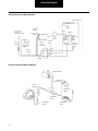
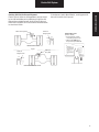
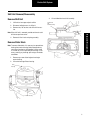
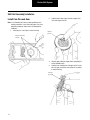
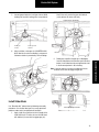
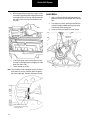
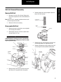
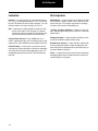
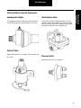
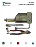
Spicer Drive Axles
®
Service Manual
AXSM0029
September 2007
General Information
General Information
The description, testing procedures, and specifications contained in this service publication were current at the time of printing.
Dana reserves the right to discontinue or modify its models and/or procedures and to change specifications at any time without
notice and without incurring obligation.
The recommendations of the vehicle manufacturer should be considered as the primary source of service information regarding
this Spicer product. This manual is intended to be used as a supplement to such information.
Any reference to brand names in this publication is made simply as an example of the types of tools and materials recommended
for use and, as such, should not be considered as an endorsement. Equivalents, if available, may be used.
IMPORTANT NOTICE
This symbol is used throughout this
publication to call your attention to areas
in which carelessness or failure to follow
specific procedures may result in
personal injury and/or component
malfunction or damage.
WARNINGS: Used in areas
where failure to follow listed
procedures creates a high
probability of personal injury
to the servicing technician.
Anyone departing from the
instructions contained in this
publication through procedures
used or choice of tools, materials
and parts may jeopardize his personal
safety and/or the safety of the vehicle user.
CAUTIONS: Used in areas
where failure to follow listed
procedures may cause personal
injury due to component
damage or subsequent malfunction.
Always use genuine Spicer replacement parts.
Table of Contents
Electric Shift System
Air Shift System
Introduction
Electric Shift System . . . . . . . . . . . . . . . . . . . . . . . . . 1
Mechanical Operation . . . . . . . . . . . . . . . . . . . . . . . . 2
Troubleshooting . . . . . . . . . . . . . . . . . . . . . . . . . . . . 5
Shift Unit Removal/Disassembly
Remove Shift Unit . . . . . . . . . . . . . . . . . . . . . . . . . . . 8
Remove Slider Block . . . . . . . . . . . . . . . . . . . . . . . . . 8
Remove Circuit Board and Motor . . . . . . . . . . . . . . . 9
Remove Gear and Cam Pins . . . . . . . . . . . . . . . . . . 10
Cleaning. . . . . . . . . . . . . . . . . . . . . . . . . . . . . . . . . . 10
Lubrication . . . . . . . . . . . . . . . . . . . . . . . . . . . . . . . 10
Sealing. . . . . . . . . . . . . . . . . . . . . . . . . . . . . . . . . . . 10
Shift Unit Assembly/Installation
Install Cam Pins and Gear . . . . . . . . . . . . . . . . . . . .
Install Slider Block . . . . . . . . . . . . . . . . . . . . . . . . . .
Install Motor . . . . . . . . . . . . . . . . . . . . . . . . . . . . . .
Install Circuit Board . . . . . . . . . . . . . . . . . . . . . . . . .
Install Shift Unit . . . . . . . . . . . . . . . . . . . . . . . . . . . .
11
12
13
14
15
Air Shift System
Description . . . . . . . . . . . . . . . . . . . . . . . . . . . . . . .
Operation . . . . . . . . . . . . . . . . . . . . . . . . . . . . . . . .
Air Shift Unit . . . . . . . . . . . . . . . . . . . . . . . . . . . . . .
Description and Operation (Shift Unit) . . . . . . . . . .
Troubleshooting . . . . . . . . . . . . . . . . . . . . . . . . . . .
19
19
20
20
21
Shift Unit Removal/Disassembly
Remove Shift Unit . . . . . . . . . . . . . . . . . . . . . . . . . .
Disassemble Shift Unit . . . . . . . . . . . . . . . . . . . . . .
Lubrication . . . . . . . . . . . . . . . . . . . . . . . . . . . . . . .
Parts Inspection . . . . . . . . . . . . . . . . . . . . . . . . . . .
22
22
23
23
Shift Unit Assembly/Installation
Assemble Shift Unit. . . . . . . . . . . . . . . . . . . . . . . . . 24
Install Shift Unit . . . . . . . . . . . . . . . . . . . . . . . . . . . 25
Air Shifter Valve Removal/Disassembly
Remove/Disassemble Air Shifter Valve . . . . . . . . . . 26
Inspection/Lubrication . . . . . . . . . . . . . . . . . . . . . . 26
Shift Unit Retrofit Kits
Retrofitting Instructions. . . . . . . . . . . . . . . . . . . . . . 16
Air Shifter Valve Assembly/Installation
Assemble/Install Air Shifter Valve . . . . . . . . . . . . . . 27
Servicing Other Electric System Components
Installation of Improved Motor Housing Cover
(Production units effective December 1989) . . . . . . 17
Speedometer Adapter . . . . . . . . . . . . . . . . . . . . . . . 18
Control Switch . . . . . . . . . . . . . . . . . . . . . . . . . . . . . 18
Servicing Other Air System Components
Quick Release Valve . . . . . . . . . . . . . . . . . . . . . . . . 28
Pressure Switch . . . . . . . . . . . . . . . . . . . . . . . . . . . 28
Servicing Other Air System Components
Additional Service Information . . . . . . . . . . . . . . . . 29
Parts Information . . . . . . . . . . . . . . . . . . . . . . . . . . 29
i
Electric Shift System
Introduction
The service procedures and specifications in this publication
cover the current Spicer 2-Speed Axle Shift Systems.
Maintenance and overhaul instructions for the Spicer 2-Speed
Axle carriers are covered in the publications listed on the back
cover.
This manual includes information on two types of Shift Systems currently in use for Spicer 2-Speed Axles; Electric and
Air.
Spicer 2-Speed Axles are driver-controlled by means of a shift
unit operated from the vehicle cab. These shift units are activated by air or electric power depending on the convenient
source in the chassis.
Because of this variation, this publication is divided into two
major segments: Electric Shift System for hydraulic-brake
chassis and Air Shift System for air-brake chassis.
Electrical Operation
Note: For component identification and wiring schematic,
refer to illustrations on pages 1, 2, 3, and 4.
Unit in Low Range Shifting to High Range
Current flows through upper contact of control switch, closed
contacts of high-range switch, and motor to ground which
starts the motor rotating. Current also continues from common motor terminal through low-range switch and to ground
through the resistor.
When motor starts, rotation of the gear allows cam ramp to
apply pressure on low-range cam pin, which allows low range
switch to open. The path to ground (through resistor) is open
and the diode prevents speedometer adapter solenoid from
being energized.
Motor rotation continues to shift axle to high range. As shift is
completed, cam ramp of gear releases high-speed cam pin to
open high-range switch and creates an open circuit to turn off
power to motor. Motor rotation is stopped quickly by means
of dynamic braking through resistor.
If, during rotation, driver decides to switch back to low range,
motor continues to turn.
ELECTRIC SHIFT UNIT CUTAWAY
Wiring Harness
and Connector
Motor
Circuit Board
Assembly
Cam Pin
(Low Range)
Switch
Spring
Gear
Gear Pin
(Eccentric)
Black Wire
Green Wire
Red Wire
Worm Gear
Cam Pin
(High Range)
Slider
Block
Flat Washer
(0.100",
2.54 mm
thick)
Opening of high-range switch has no effect since motor is
now being powered by the circuit from control switch,
through diode and low-range switch to ground at motor. In
this instance, motor continues to turn until cam pin opens
low-range switch to turn off power to motor.
Unit in High Range Shifting to Low Range
Current flows through control switch lower contact to energize speedometer adapter solenoid and through the diode and
low-range switch to common motor terminal and ground at
motor. Motor starts rotating. Current also flows through
closed contact of high-range switch and to ground through
resistor. Once gear rotates enough to apply cam pin pressure
on the high switch, circuit to ground through resistor is open.
As motor rotation continues to shift axle to low range, gear
rotates and releases cam pin on low-range switch to open
switch and open motor circuit. Motor power is turned off.
Once again, the resistor portion of the circuit provides braking
to stop motor quickly.
If, during motor rotation, driver decides to shift back to high
range, the motor continues to turn. Opening of low-range
switch has no effect since motor is now being powered
through control switch. In this instance, motor continues to
turn until gear rotation opens high-range switch to open
motor circuit.
The shift unit always remains synchronized with position of
driver's control switch.
1
Electric Shift System
As motor shuts off at 180º of gear rotation, a break in torque
by driver allows spring force (stored in the slider block
assembly) to move the swivel pin and shift fork in appropriate
direction for axle range change.
Low to High Range or High to Low Range
When shifting axle range either up or down, motor starts and
turns worm gear shaft. The gear assembly (which is meshed
with worm gear) turns and moves eccentric pin in slot area of
slider block.
When opposite axle range is selected by driver, the process is
repeated by motor turning another 180º in same direction. In
this case though, eccentric pin movement creates block
spring compression in the opposite direction.
Since driving torque holds shift fork and swivel block of the
slider block assembly in place, linear motion of slider block is
translated into compression of the internal spring.
ELECTRIC SHIFT UNIT
Cover Screw
Housing Cover
Cover Gasket
Nut (Circuit Board)
Cover Gasket
(See Note below)
Wiring Harness
and Connector
Circuit Board Assembly
Red Wire
Black Wire
Green Wire
Cam Pin
Motor Housing
Gear Washer
Gear
Gear Pin
Board Flat Washer
Nut (Gear Shaft)
Worm Gear
Motor Screw
Motor Assembly
Nut
Cable Clip
Motor Lead Wire
Gear Shaft
Slider Block &
Shaft Assembly
Electric Shift Unit Assembly
Base Housing
Housing Screw
Dowel Pin
Seal & Spring
Nut
Flat Washer (0.100", 2.54 mm thick)
Stud
Note: The new improved housing cover does not require a
gasket (see page 17).
2
General Information
Mechanical Operation
Electric Shift System
Shift System Electrical Wiring Schematic
Circuit Board
Resistor
Ground
Up-High
Range
Power Source
(Ignition or
Accessory Switch)
Down-Low
Range
Black
Motor
High
Range
NC NO
Ground
Control Switch
Circuit
Breaker
Wiring
Harness
Connector
Speedometer
Adapter
Switches
Switch Knob
Housing
Cover
Diode
Black
Wiring
Harness
Green
Red
Ground
Electrical Shift System Major Components
Shift Unit Switch
Plug and Cable
Assembly
Electric
Shift Unit
Speedometer
Adapter
Front Wiring
Harness
Rear Wiring
Harness
3
Low
Range
NO NC
Circuit Breaker
or Fuse
Electric Shift System
General Information
Slider Block Inspection Procedure
Bottom of
Base Housing
• Remove shift unit from axle.
• Move slider block from side to side.
Make sure slider block moves freely
in housing.
4
Electric Shift System
Troubleshooting
Troubleshooting Guide
This chart begins with an improperly operating shift unit. Use with illustrations on pages 3, 4 and 6 to help isolate the problem.
Follow the possible solutions as an aid to system repair.
Axle doesn’t shift ranges.
• Check the circuit breaker.
• Is the circuit breaker closed?
Yes
Check for power at the shift unit
connector.
• Is there a voltage reading of 9V
or more?
Yes
Remove shift unit from axle and
apply voltage.
• Does unit shift properly?
Yes
Inspect slider block from bottom
of shift unit. See page 4
• Check to see if slider block is loose
or missing.
• Is slider block in good operating
condition?
Yes
Inspect appearance of shift fork
and check fit with depth card.
• Does the fork match the depth
card output? (See page 6)
Yes
Remove and inspect axle shift parts.
• Are engagement surfaces severely
worn, chipped or broken?
Yes
• Replace worn components.
• Repeat troubleshooting procedure.
5
No
• Reset circuit breaker or
replace fuse.
• Repeat troubleshooting procedure.
No
• Check the battery, cab switch,
wire harness, and connectors.
• Repeat troubleshooting procedure.
No
• Disassemble and service shift unit.
(See page 8)
• Repeat troubleshooting procedure.
No
• Replace slider block assembly
(See page 8)
• Repeat troubleshooting procedure.
No
• Rework or replace shift fork.
• Repeat troubleshooting procedure.
No
End of diagnostics
Electric Shift System
Shift Fork Fit-up Card
If interference at points A and B exists, carefully grind shift
fork until it matches the fit-up card.
Shift Fork
Range Position
Hi
Shift Fork
Range Position
Shift Fork Fit-up Card
(Part No. 128039)
• Fit-up Card must set flush
on mounting surface of axle
• Shift fork must NOT touch
Fit-up Card at points A and B
2-Speed Shift Fork Fit-Up Card
FORWARD-REAR AXLE
Figure 1
Lo
General Information
Checking Shift Fork Position and Alignment
Electric shift unit failure or shifting problems may be caused
by the shift fork binding on the slider block. Check the shift
fork position and alignment with the Shift Fork Fit-Up card.
Refer to the instructions on the card and the illustration below
to check the shift fork.
Shift Fork
Fit-up Card
Procedure:
1. Shift axle to high range so fork is
square to axle face.
2. Remove shift unit and rubber boot.
3. Drop card over shift unit as shown
in (fig. 1) until card touches carrier
surface or interferes with fork.
4. If no interference, fork is OK.
Go to step #6.
5. If card interferes at A or B, carefully grind fork to fit template.
6. Replace boot and reassemble unit.
Printed in U.S.A.
Dana service keeps
you on the road.
For technical assistance call
1-877-777-5360
anywhere in North America
Part no. 128039
10M/1290/MP
Copyright Dana 1991
All right reserved
Lo
Hi
REAR-REAR AND SINGLE AXLES
6
Electric Shift System
Parts Service Kits
Expanded Service Kits
Note: The new
and improved
housing cover
does NOT
require a
gasket
(see page 17).
7
SERVICE KIT NO.
DESCRIPTION
ITEMS INCLUDED
211319
Circuit Board and Cover Kit
1-7, 18-19
113745
Motor and Lube Kit
10, 18-19
113746
Drive Gear and Cam Pin Kit
5, 9, 12-14, 18
113759
Slider Block and Lube Kit
15, 18
113753
Connector and Harness Kit
20-26
Electric Shift System
Shift Unit Removal/Disassembly
Remove Shift Unit
3.
1.
Shift axle to low range and park vehicle.
2.
Disconnect wiring harness at shift unit.
3.
Remove nuts, flat washers and shift unit from carrier.
Lift out slider block and shaft assembly.
Slider Block
and
Shaft Assembly
4.
Removal / Disassembly
Note: When shift unit is removed, provide container to catch
oil that escapes from carrier.
Remove shift unit seal and spring assembly.
Remove Slider Block
Note: To remove slider block, it is necessary to separate base
housing from motor housing. Gasket compound may
cause these housings to stick together. Use the motor
as a handle to assist in separating the housings. If necessary, carefully pry housings apart using a thin-bladescrewdriver.
1.
Remove cap screws fastening base housing to
motor housing.
2.
Lift motor housing off base housing.
Base
Housing
Motor Housing
8
Electric Shift System
Remove Circuit Board and Motor
1.
Remove
Circuit Board
Washer
Disconnect lead wires at cover terminals. Remove
cover and gasket. Remove circuit board locknut.
Circuit Board
Locknut
Lead Wires
Cover Terminals
HOUSING COVER REMOVAL
3.
Remove circuit board mounting washer.
Remove cap screws fastening cover to motor housing.
Note: Gasket compound may cause cover to stick to housing.
If necessary, carefully pry it loose, using a thin-blade
screwdriver.
2.
4.
5.
Remove cap screws fastening motor.
6.
Lift motor to separate it from the housing.
Note: Gasket compound may cause motor to stick to housing.
If necessary, separate motor from housing by carefully
prying, using a thin-blade screwdriver.
7.
Remove motor, carefully guiding the motor wire and
terminal through the housing hole.
Lift circuit board out to gain access to motor lead
wire (black). Disconnect this wire then remove circuit board.
MOTOR REMOVAL
Disconnect Motor
Lead Wire
Pry motor loose
with screwdriver
9
Electric Shift System
Remove Gear and Cam Pins
1.
Remove gear locknut. Use deep-well socket while
holding shaft end with locking pliers.
2.
Remove ground lead wire.
Cleaning
After shift unit disassembly, clean all parts (with exception of
the motor and circuit board), in a suitable commercial solvent.
Dry with clean, lint-free cloth or compressed air before lubricating or reassembly.
GEAR SHAFT LOCKNUT REMOVAL
Make sure all residual gasket compound is removed from
mating surfaces.
WARNING: Gasoline is not an acceptable solvent because
of its extreme combustibility. It is unsafe in the workshop
environment.
Lubrication
Use locking pliers
and deep-well socket
to loosen nut
3.
Lift shaft and gear assembly out of housing.
Note: The cam pins are removed from the gear side of housing. Do not disturb the switch spring.
4.
Lubrication of the shift unit is not required except when unit
has been disassembled. Instructions are contained in the shift
unit assembly procedures in this manual.
Note: Use only “Rheolube 362” for shift lubrication. Use of
other lube types may cause shift unit operational problems under certain low temperature conditions. A tube
of this lubricant is included in Spicer Shift Unit Service
Kits. It can also be purchased separately under Part
No. 113741.
Remove cam pins from housing.
Remove cam pins
from housing
Sealing
CAUTION
CAUTION: Use approved gasket compound (Part No.
113771) to seal shift unit cover and other components.
Standard RTV sealant may cause corrosion of electrical
components.
Proper sealing of the shift unit mating surfaces is essential for
long life and trouble-free operation. For effective sealing, use
approved gasket compound. During reassembly, make sure
the mating surfaces are clean and that the compound pattern
is not disturbed. Also, the gasket compound will set in 20
minutes. Assemble components before compound sets or
reapply.
10
Removal / Disassembly
WARNING
Electric Shift System
Shift Unit Assembly/Installation
Install Cam Pins and Gear
2.
Lubricate both sides of gear washer and gear face
that contacts gear washer.
Note: Use “Rheolube 362” lubricant during following reassembly procedures. Use of other lube types may cause
operational problems under certain low temperature
conditions.
1.
Lubricate pins. Install pins in motor housing.
Lubricate
gear face
Lubricate and install
cam pins
3.
Liberally apply lubricant on gear teeth. Completely fill
cavities between teeth.
4.
Lubricate the shoulder part of the gear shaft. Assemble shaft, gear and washer, then place this assembly
in motor housing.
Lubricate
gear teeth
11
Electric Shift System
5.
Also fill the cavity next to the gear with lubricant
(cavity adjacent to motor shaft hole).
Connect ground lead wire. Install gear locknut. While
holding shaft end with locking pliers, torque locknut.
SLIDER BLOCK LUBRICATION
Install gear
locknut
6.
Connect ground
lead wire
After installation, rotate gear in a COUNTERCLOCKWISE direction to make sure binding is not present.
Clockwise rotation is prevented by shift unit design.
Lubricate
2.
Note: It may be necessary to move the slider block in one
direction or the other to engage the gear pin.
Gear pin
Rotate gear to
check for binding
Install Slider Block
Use “Rheolube 362” lubricant during following reassembly
procedures. Use of other lube types may cause operational
problems under certain low temperature conditions.
1.
SLIDER BLOCK INSTALLATION
Apply a light film of lubricant to the full length of the
slider block shaft. Fill entire slot area of slider block
with lubricant (the area which engages gear pin).
12
Assembly / Installation
Rotate gear to position the gear pin at 90 degrees
from the slider block shaft centerline (see illustration
below). Install slider block by nesting the block shaft
in the recessed pockets in base housing.
Electric Shift System
3.
With housing mating surfaces clean, apply a continuous bead of approved gasket compound around the
outer edge of the base housing. Align the dowel pin
with hole in motor housing and assemble the two
housings.
Install Motor
1.
Apply a continuous bead of approved gasket compound on motor base around motor shaft and lead
wire.
2.
Place motor on housing, guiding the lead terminal
and wire through the proper opening and placing
shaft through motor housing hole.
3.
Install cap screws and tighten to correct torque.
Apply gasket
compound
Apply gasket compound
4.
Install housing cap screws loosely. Make sure that
housings are mating properly by wiggling the slider
block from side to side.
5.
Torque housing cap screws.
Note: There should be some slider block free play. If block is
rigid, loosen cap screws, reposition block and tighten
cap screws finger-tight. Recheck slider block free play.
Move slider block from side
to side to make sure housings
are properly mated
13
Electric Shift System
Install Circuit Board
1.
3.
Install circuit board washer on gear shaft and on top
of gear locknut.
Install circuit
board washer
Install circuit board on gear shaft and install locknut.
Torque locknut.
IMPORTANT
IMPORTANT: If a new housing cover is required, install the
improved cover (see page 17 for instructions). Original
cover is not available.
Install circuit
board assembly
Install board locknut
Connect motor lead wire to circuit board terminal.
4.
To continue assembly of the shift unit when reusing
the original cover, proceed as follows:
5.
Apply RTV Electrical Grade Gasket Compound in
(PN 113771) cover gasket groove. Install gasket.
Apply gasket compound to gasket mating surface,
circling screw holes.
6.
Connect circuit board lead wires to cover terminals
(see next illustration). Carefully push wires back in
housing.
Note: Exert care when repositioning lead wires to prevent
smearing or destroying gasket compound.
Connect
motor lead
14
Assembly / Installation
2.
Electric Shift System
7.
Place cover in position on motor housing and install
cap screws. Torque cover cap screws.
Red Wire
Install Shift Unit
Note: Before installation, place shift unit in low range. This
can be accomplished by connecting chassis wiring harness to shift unit cover and operating control switch (in
cab), or apply 12-volt power supply to low range and
ground terminals in shift unit cover (see wiring schematic, page 3).
Green Wire
Black
Wire
1.
Lubricate shift fork in seal area. Install seal and
spring assembly on carrier.
2.
Place shift unit on mounting studs, making certain
shift unit actuating swivel pin engages slot in shift
fork. Install flat washers (0.100", 2.54 mm thick) and
nuts.
3.
Torque nuts. Connect wiring harness.
IMPORTANT
Connect lead wires
IMPORTANT: Before installing a rebuilt or replacement shift
unit, check fit of shift fork using a “fit-up” card (see
page 6).
Note: Cover includes terminal identification for lead wires:
B - Black, G - Green, R - Red inside and LO, GND and HI
outside.
15
Electric Shift System
Shift Unit Retrofit Kits
5.
If shift unit does not operate, unplug new harness
connector and test for power and voltage continuity
at connector terminals.
Note: In some special situations, the new unit cannot be used.
Refer to appropriate Spicer Parts Books for detailed
application and part no. information.
The following instructions are a condensed version for retrofitting a new shift unit. Detailed instructions are contained in
the Retrofit Kit.
Wiring
Harness
Shift
Unit
Assembly
Cable
Clip
Clip
Nut
Connect new wiring harness to new shift unit.*
Check shift unit operation before mounting on differential carrier. Operate driver control switch in low
and high range and observe new shift unit operation.
If shift unit operates, install on carrier as follows:
6.
Use new seal and spring assembly.* Mount seal on
carrier studs.
7.
Install shift unit. Install flat washers and nuts.
Torque nuts.
Note: Make sure to use the mounting washers* (0.100",
2.54 mm thick) furnished with kit.
8.
Attach cable clip* to harness near motor and fasten
to motor stud with nut*. Torque clip nut.
9.
Secure harness to chassis with tie wraps.* Leave
adequate slack to allow for axle movement.
Flat Washer (2)
IMPORTANT
(0.100", 2.54mm thick)
Connectors (3)
Spring
Seal
Tie Wraps (2)
COMPONENTS OF TYPICAL RETROFIT KIT
IMPORTANT: Shift Unit Replacement.
Before installing a rebuilt or new shift unit, check fit of shift
fork to slide block pivot using a “Fit-up” Card or Template
(PN 128039). These cards are furnished with new shift units
retrofit and slide block kits. Instructions are contained on
the card (see illustration) (also see page 6 instructions).
Retrofitting Instructions
*These parts are included in Retrofit Kit.
1.
Remove existing shift unit.
2.
Remove and discard seal and spring.
3.
Cut existing wiring harness (approx. 6" - 8"). Identify
wires (Low Range, High Range and ground).
4.
Connect new wiring harness to existing harness,
using connectors* furnished in kit.
EXISTING WIRING HARNESS
2-Speed Shift Fork Fit-Up Card
Procedure:
1. Shift axle to high range so fork is
square to axle face.
2. Remove shift unit and rubber boot.
3. Drop card over shift unit as shown
in (fig. 1) until card touches carrier
surface or interferes with fork.
4. If no interference, fork is OK.
Go to step #6.
5. If card interferes at A or B, carefully grind fork to fit template.
6. Replace boot and reassemble unit.
Printed in U.S.A.
Dana service keeps
you on the road.
For technical assistance call
1-877-777-5360
anywhere in North America
Part no. 128039
10M/1290/MP
Copyright Dana 1991
All right reserved
NEW HARNESS*
Ground
to Green Wire (Ground)
Low
to Black Wire (Low)
High
to Red Wire (High)
16
Retrofit Kits
The new Spicer Electric Shift Unit is a completely new design
and shares no common parts with existing shift units. However, it is completely interchangeable as a unit for service
replacement. Retrofit Kits are available to convert to the new
shift unit.
Electric Shift Sytem
Servicing Other Electric System Components
Installation of Improved Motor Housing
Cover (Production units effective December 1989)
CAUTION
CAUTION: When removing material, use care to avoid filing
into the threads of the motor mount fastener.
See Detail Below
The new cover (PN 113786) has a continuous sealing lip
around the outside edge which improves sealing against road
environment contamination. Previous cover is no longer available. Units currently in the field must be modified whenever a
new cover is installed.
Interference Area
Cover
Upper
Housing
Modification: Because the new cover encloses the entire rim
of the units cast nose piece, the base of the motor mounting
flange must be relieved slightly to prevent interference.
Motor
Note: This modification is only needed if a notch is NOT
present in the motor housing flange.
1.
Remove four (4) cover screws. Retain 3 screws.
Note: The service kit includes a screw which is 1/4" longer
than the previous cover screws.
2.
3.
Place the new cover into position on the shift unit
housing and draw a reference line on the motor base
to show the width of the area to be modified.
Using a file or small die grinder, remove material
from the motor base (as shown in Fig. 1. The notch
should be at least 0.100" (2.5mm) deep and 0.150"
(3.8 mm) wide. Trial fit the cover during modification.
0.100"
2.5 mm
Upper
Housing
0.150"
4.0 mm
Motor
Fig. 1 - Electric Shift Unit Cover Fit Modifications
4.
With the modification complete, install the new cover
as follows:
5.
Using RTV gasket compound (supplied with the service kit), apply a thin bead on top edge of motor
housing.
Note: The new cover does not require a gasket.
CAUTION
CAUTION: Always use RTV Electrical Grade Gasket Compound (PN 113771). Standard forms of RTV generate
acetic acid which will damage shift unit components. Use
gasket compound sparingly. Excessive use of compound
could damage internal parts.
17
Electric Shift Sytem
Speedometer Adapter
Install long screw
from kit in this
location
Install 3 previously removed screws
in these locations
Fig. 2 - Cover Screw Location
Install the cover capscrews as shown in Fig. 2.
Note: The 3 screws from prior installation should be used in
all but the hole closest to the electrical connector. The
new (longer) screw supplied with the kit must be
installed in the hole shown.
7.
Control Switch
For inspection or replacement, the control switch can easily
be removed by sliding the rubber boot up to the knob, then
separate switch from harness.
Inspect switch for loose connections and other visual defects
that may cause short circuit or electrical failure. Replace a
faulty switch as an assembly.
Tighten all capscrews to 25-30 Lb.-In. (2.8-3.4 N.m)
Do not over tighten.
18
Servicing Other
Components
6.
The speedometer adapter is lubricated and sealed for life of
the unit. No maintenance is required. Replace a faulty unit.
Air Shift System
Air Shift System
* For Vehicles
Not Equipped with
Automatic Safety Brakes
+ For Vehicles with
Transmission Drive
Speedometers
Axle Shift Unit
Quick Release Valve
+Speedometer Adapter
Exhaust
2-Speed Air
Shifter Valve
+ Pressure Switch
(normally closed)
* Solenoid Valve
White
Dry Air Tank
Red
* Circuit
Breaker
Green
Exhaust
* Ignition or
Accessory Switch
Description
Operation
The basic system consists of:
In operation, the air shifter valve (in gear shift knob) supplies
air through the quick release valve to the axle shift unit. Air
pressure in the shift unit shifts axle to High range. To shift
axle to Low range, air pressure is exhausted at shifter valve,
which exhausts air pressure at quick release valve, allowing
shift unit to return to Low range.
1.
A 2-position manually operated air shifter valve.
2.
A quick release valve.
3.
An air shift unit.
The system operates at reservoir tank air pressure.
For vehicles not equipped with automatic safety brakes, an
ignition-controlled solenoid valve exhausts the system and
down-shifts axle when ignition switch is turned off. The electrical circuit is protected by a circuit breaker.
For vehicles equipped with transmission drive speedometer, the system includes a speedometer adapter. Operation is
controlled by an electric switch (normally closed—opened by
air pressure). This switch is mounted on or near the quick
release valve.
19
Low Range Operation — Shifter knob is in “LO”, shifter valve
is closed and no air pressure is present to shift unit. Axle is
held in Low range by shift unit return spring.
High Range Operation — Shifter knob is in “HI”, shifter valve
is opened to allow air pressure through quick release valve to
shift unit. Axle is held in High range by air pressure in the shift
unit.
Air Shift System
Air Shift Unit
“O” Ring
Lock Nut
Housing Cover
(Piston End)
Push Rod
“O” Ring
Lock Nut
Washer
Piston
Compression
Spring
“O” Ring
Felt Oilers
Piston
Stop
Cap Screw
(Plug)
Screw and
Washer
Assembly
Housing
Cover
Cover
Gasket
“O” Ring
Cover
Bolt
Actuating
Lever Pin
Housing
General Information
Housing Bearing
Oil Filler and
Level Plug
Cover
Bearing
Description and Operation (Shift Unit)
The Air Shift Unit is engineered for efficient performance and
built for reliable, service-free operation.
Operation of the unit is as follows: The shift unit is mechanically connected to the axle shift fork and shifts axle into Low
or High range.
Clevis Pin
Actuating Lever, Pin,
and Block Assembly
Note: A harsh environment kit (consisting of a vent filter and
fittings) is available for shift units operating in unusually
wet or dirty conditions. For additional information contact Dana Service Support.
Note: Air Shift Units are also used on Spicer Controlled Traction Differential and Dual Range Tandem Axles. Refer to
Spicer Service Manuals EA-47, EA-44 and EA-45.
The unit consists of an air chamber, piston, compression
spring and mechanical linkage. When air is admitted to the
chamber or cylinder, the piston travels downward against a
compression spring, transferring motion through a push rod
and actuating lever to the shift fork, shifting the axle into High
range. Exhaust of air pressure permits the heavy-duty spring
to return the axle gearing to Low range.
20
Air Shift System
Troubleshooting
Check for Air Leaks
2.
A simple method for quickly locating troubles in the system is
to listen for possible air leaks and for sound which would indicate shift unit operation. Proceed as follows:
1.
Turn ignition switch “ON” to energize and open solenoid valve. Move shifter knob to “HI”. In this position, air pressure should be present in the entire
system. Check for air leaks.
2.
With shifter knob in “LO”, air pressure should be
present only up to the shifter valve.
3.
To check axle for shifting, operate shifter knob back
and forth from “LO” to “HI”. If the shift unit is operating, a definite reaction will be evident by sound of
parts movement.
4.
If air pressure is satisfactory and shift unit does not
operate, disassemble and inspect shift unit.
Check Pressure Switch
In Low Range, the pressure switch is closed and electrical circuit is complete to the speedometer adapter. In High Range,
air pressure opens the pressure switch, and breaks the electric circuit to the speedometer adapter.
To check pressure switch operation, shift to High Range and
probe switch terminals. No voltage should be present.
Replace a faulty pressure switch as an assembly.
Check Electrical System
(with solenoid valve)
1.
21
When ignition switch is “ON” solenoid valve is energized and air pressure is available to operate the system. When ignition switch is “OFF”, solenoid valve is
de-energized and exhausts the system which downshifts axle to low range. Check wiring and circuit
breaker for defects that would cause shorts or open
circuits.
Make sure valve has a good ground connection to
the frame. With power at valve, check operation as
follows:
Disconnect lead wire and air line outlet at valve
and install air pressure gauge.
Apply power to valve and observe air gauge
reading. Operating pressure should be approximate reservoir pressure.
If gauge indicates approximate pressure, valve
is okay.
If gauge indicates low or no pressure, valve is
faulty. Replace valve assembly.
Check Quick Release Valve
The quick release valve provides a means of quickly exhausting air from system when axle is shifted from High to Low
Range.
To check valve operation, listen for audible air exhaust from
valve when shifting axle from High to Low Range. Replace a
faulty quick release valve as an assembly.
Check Speedometer Adapter
1.
Make sure adapter is grounded to vehicle chassis.
2.
Check wiring for shorts or grounds and trace electrical circuit from ignition switch to speedometer
adapter.
3.
Check for power supply at adapter terminal. With air
shifter valve in High Range, pressure switch is open
and power is not delivered to adapter. With shifter
valve in Low Range, the pressure switch is closed
and power is delivered to operate the speedometer
adapter. If power supply is okay, adapter is faulty.
Replace adapter assembly.
Air Shift System
Removal / Disassembly
Shift Unit Removal/Disassembly
Remove Shift Unit
1.
4.
Disconnect air line at shift unit cover. Remove nuts,
flat washers and piston air shift unit from differential
carrier.
Compression
Spring
Note: When shift unit is removed, provide container to catch
oil that escapes from reservoir.
2.
Remove compression spring and piston stop from
bore of shift unit housing.
Remove shift fork seal and spring.
Piston
Stop
Disassemble Shift Unit
1.
Remove cap screws, lock washers, cover and gasket
from housing. Drain lubricant.
2.
Remove bolts, locknuts, and cover at piston end of
housing. Remove “0” ring.
“O” Ring
CAUTION
CAUTION: During the following procedure, the piston will
pop out of housing under spring pressure. Exercise caution
to prevent possible injury.
5.
Remove clevis pin, then remove push rod from shift
unit housing. Remove “0” ring from push rod.
6.
Remove actuating lever and pin assembly from shift
unit housing. Do not disassemble actuating lever.
Piston
Felt Oilers
“O” Ring
“O” Ring
Actuating
Lever
Assembly
Shift Fork
Swivel Pin
Compression
Spring
Actuating
Lever
Shift Unit
Housing
Piston Rod
Clevis Pin
3.
Remove locknut, flat washer, and piston from push
rod. Remove “0” ring and felt oilers from piston.
Actuating
Lever Pin
22
Air Shift System
Lubrication
Parts Inspection
Lubricant — Use SAE 10 motor oil* for temperatures above
0° F (-18° C). For temperatures below 0° F (-18° C), mix three
parts of SAE 10 motor oil with one part of kerosene. This cold
weather mixture can be safely used up to 32° F (0° C).
Shift Fork Seal — Inspect shift fork seal for defects and tight
fit on shift fork. A spring is used to assure a closer fit of seal
around shift fork. If this spring is not present on axle being
serviced, install one when reassembling unit.
Note: *Commercially available automatic transmission fluid
may be used in place of SAE 10 motor oil. Automatic
transmission fluid can be used for all temperatures. Do
not mix kerosene with automatic transmission fluid.
“0” Rings, Felt Oilers and Gasket — Replace “0” rings, felt
oilers and cover gasket when piston air shift unit is disassembled for repair.
Lubricant Check and Level — Each 20,000 miles or six
months, remove pipe plug in shift unit housing cover to check
lubricant level. Lube should be level with bottom of filler hole.
Lubricant Change — At least once a year remove shift unit
housing cover and drain old lubricant. Wash parts thoroughly
and air dry. Reinstall cover. Remove pipe plug in cover. Fill
through pipe plug opening until lube is level with bottom of
filler hole.
23
Compression Spring — Inspect spring for distortion, cracks,
or other visual defects. Replace a faulty spring.
Actuating Lever and Pins — Inspect lever pins and bearings
for worn or grooved condition. Inspect actuating lever and
push rod for worn or elongated holes at point where they are
connected. Replace faulty parts.
Piston — Inspect piston friction surface for worn, grooved or
damaged condition which will affect the piston movement in
cylinder. Replace a faulty piston.
Air Shift System
Shift Unit Assembly/Installation
Assemble Shift Unit
4.
Note: Prior to assembly, the piston felt oilers should be
soaked in SAE 10 oil for one hour. Lubricate “0” rings
with a high viscosity silicone oil or barium grease “0”
ring lubricant.
Assemble pin to actuating lever and install this
assembly in shift unit housing.
2.
Assemble “0” ring and piston to push rod and fasten
with flat washer and locknut. Torque locknut. Install
felt oilers and “0” ring on piston.
PISTON AND
PUSH ROD
ASSEMBLY
INSTALLATION
PUSH ROD CLEVIS
PIN INSTALLATION
Press
Actuating
Lever
Press
Shift
Unit
Housing
Assembly / Installation
1.
Apply pressure to piston until actuating lever is in
alignment with push rod end. Install clevis pin.
Release press.
Push
Rod End
Piston
Locknut
Clevis
Pin
Actuating
Lever
5.
Place cover gasket in position on shift unit housing
then install cover and bearing assembly and fasten
with cap screw and lock washers. If necessary, use a
sealer on threads of cap screws to prevent any leaking. Torque cap screws.
6.
Place “0” ring in groove of shift unit housing, then
install housing cover and secure with bolts and locknuts. Torque locknuts.
7.
Fill Shift unit with SAE 10 oil or automatic transmission fluid (see Lubrication page 23) when axle is
installed in vehicle.
Pin
CAUTION
CAUTION: During the following procedure using a press,
make certain components are properly aligned in press to
prevent possible personal injury or damage to parts.
3.
Insert piston stop and compression spring in shift
unit housing. Place piston and push rod assembly in
housing. Position housing assembly in arbor press.
24
Air Shift System
Install Shift Unit
25
1.
Lubricate shift fork. Slide seal and spring assembly
over fork and place on differential carrier studs.
2.
Place shift unit on mounting studs and make certain
shift fork actuating lever engages slot in shift fork.
Install flat washers and stud nuts. Torque nuts.
3.
When axle is installed in vehicle, fill shift unit housing to level of filler plug with SAE 10 oil. Coat threads
of filler plug with sealer and install plug.
4.
Connect air lines to shift unit cover.
Air Shift System
Air Shifter Valve Removal/Disassembly
Remove/Disassemble Air Shifter Valve
CAUTION
CAUTION: Air supply to valve must be shut off before the
valve is serviced.
Inspection/Lubrication
Each 50,000 miles, disassemble, inspect and clean, then
lubricate moving parts with barium-base grease. No other
type lubricant should be used.
The shifter valve can be disassembled for service without
removing the assembly from the gear shift lever.
1.
Remove screw from cover, then lift off cover and
remove shifter knob, knob spring, shifter plate, “0”
ring guide and “0” ring from valve housing.
2.
If housing requires replacement, disconnect air
lines, loosen jam nut, then unscrew housing from
shifter lever.
AIR
SHIFTER
VALVE
Cover Screw
Cover
Valve Removal /
Disassembly
“O” Ring
“O” Ring Guide
Shifter Plate
Knob
Spring
Housing
Shifter
Knob
Jam Nut
26
Air Shift System
Air Shifter Valve Assembly/Installation
Assemble/Install Air Shifter Valve
1.
2.
If housing was removed, install jam nut on shift
lever. Thread housing on shift lever and tighten jam
nut. Connect air lines. Air shift valve knob should be
positioned at 9:00 o'clock. Lubricate moving parts
with barium-base grease during assembly.
4.
Hold shifter plate in position with one hand, then
install spring and shifter knob. Install cover and fasten with screw.
SHIFTER KNOB INSTALLATION
Place shifter plate in mounting position on valve
housing.
SHIFTER VALVE PLATE INSTALLATION
Shifter Plate
Valve Housing
Shifter
Knob
Knob Spring
3.
Pre-assemble guide and “0” ring, then place this
assembly in mounting position in shifter plate.
“O” RING AND GUIDE INSTALLATION
“O” Ring
“O” Ring
Guide
Shifter Plate
27
Air Shift System
Servicing Other Air System Components
Quick Release Valve
The speedometer adapter is lubricated and sealed for life of
the unit. No maintenance is required. Replace a faulty unit.
If quick release valve fails to operate properly, it may be
repaired as follows: Disassemble valve. Inspect valve body,
valve seat and spring (if used) for evidence of faulty operation. Replace faulty parts, then reassemble valve.
Servicing Other
Components
Speedometer Adapter
Solenoid Valve
Replace solenoid valve as an assembly. The valve should not
be serviced.
Pressure Switch
Replace pressure switch as an assembly.
28
Shift Systems
Additional Service Information
Service information on 2-Speed Axle shifting components
may be found in the appropriate Axle Service Publications.
Parts Information
Complete information for identifying replacement parts for 2Speed Shift Systems may be found in the appropriate Parts
Publications.
29
For spec‘ing or service assistance, call 1-877-777-5360 or visit our website at www.dana.com
Dana Commercial Vehicle Products Group
3939 Technology Drive
Maumee, Ohio, USA 43537
www.dana.com
All applications must be approved by the Application Engineering Department. Specifications and/or design are subject to change without notice or obligation.
Printed in USA
AXSM-0029 09/07