1
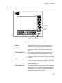
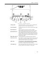
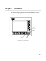
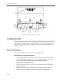
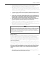
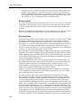
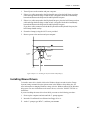
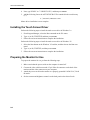
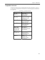
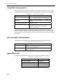
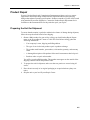
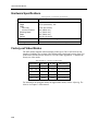
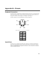
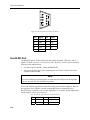
9407 Industrial Monitor P/N 110342-001B 1996 XYCOM, INC. Printed in the United States of America Part Number 110342-001B XYCOM 750 North Maple Road Saline, Michigan 48176-1292 (313) 429-4971 Xycom Revision Record Revision Description Date A B Manual Released Manual Updated (incorporates PCN 199) 6/96 8/96 Trademark Information Brand or product names are registered trademarks of their respective owners. Windows is a registered trademark of Microsoft Corp. in the United States and other countries. Copyright Information This document is copyrighted by Xycom Incorporated (Xycom) and shall not be reproduced or copied without expressed written authorization from Xycom. The information contained within this document is subject to change without notice. Xycom does not guarantee the accuracy of the information and makes no commitment toward keeping it up to date. Address comments concerning this manual to: xycom Part Number: 110342-001B Technical Publications Department 750 North Maple Road Saline, Michigan 48176-1292 Xycom Manual Bug Report This form is used to track errors that may exist in our manuals and to incorporate improvements. Please describe any errors found in this manual or provide suggestions on how to improve its usefulness. We appreciate your input. To return this form, fold it in half so the postage-paid* side shows, and tape it closed. Current Information Page number(s): Figure number(s): Information as currently printed: Proposed Change(s) Information as it should be printed: Additional information: Address (optional) Name Title Company Street Address City State ZIP Phone This box for Xycom use only. Date Received: Date Resolved: Manner Resolved: PCN #: Revision: Void: 9407 Industrial Monitor manual, 110342-001B *If mailing this card from outside the United Sates, please use an envelope with the appropriate postage. United States FCC Part 15, Subpart B, Class A EMI Compliance Statement Note: This equipment has been tested and found to comply with limits for a Class A digital device, pursuant to part 15 of the FCC Rules. These limits are designed to provide reasonable protection against harmful interference when the equipment is operated in a commercial environment. This equipment generates, uses, and can radiate radio frequency energy and, if not installed and used in accordance with the instruction manual, may cause harmful interference to radio communications. Operation of this equipment in a residential area is likely to cause harmful interference in which case, the user will be required to correct the interference at his own expense. For Canadian Users This digital apparatus does not exceed the Class A limits for radio noise emissions from digital apparatus as set out in the radio interference regulations of the Canadian Department of Communications. Le présent appareil numérique n’émet pas de bruits radioélectriques dépassant les limites applicables aux appareils numériques de Class A prescrites dans le Règlement sur le brouillage radioélectrique édicté par le ministère des Communications du Canada. For European Users - WARNING This is a Class A product. In a domestic environment this product may cause radio interference in which case the user may be required to take adequate measures. Installation: Electromagnetic Compatibility Warning This monitor has been tested to EN 61000-4-8 for immunity to 50 Hz, 3 A/m magnetic fields. Magnetic fields of this magnitude have the potential to create slight “jitter” on the display. This jitter is the result of the magnetic field effecting the electron beam, which is inherent to CRT technology and so cannot be reduced through electrical design. In order to minimize the potential for this effect, do not install the monitor near devices which can be executed to create significant magnetic fields. Examples are devices with inductive coils such as alarm bells, speakers, relays, transformers, motors, or conductors which are expected to conduct high levels of current. If screen jitter occurs and is due to 60 Hz AC power, then setting the monitor vertical refresh rate to 60 Hz may correct the problem. Otherwise, set the vertical refresh rate to the highest possible frequency. the connection of non-shielded equipment interface cables to this equipment will invalidate FCC EMI and European Union EMC compliance and may result in electromagnetic interference and/or susceptibility levels which are in violation of regulations which apply to the legal operation of this device. It is the responsibility of the system integrator and/or user to apply the following directions which relate to installation and configuration: 1. All interface cables must include shielded cables. Braid/foil type shields are recommended. Communication cable connectors must be metal, ideally zinc die-cast backshell types, and provide 360° protection about the interface wires. The cable shield braid must be terminated directly to the metal connector shell; ground drain wires alone are not adequate. 2. Protective measures for power and interface cables as described within this manual must be applied. Do not leave cables connected to unused interfaces or disconnected at one end. Changes or modifications to this device not expressly approved by the manufacturer could void the user’s legal authority to operate the equipment. Chapter 1 – Introduction Product Overview The 9407 Industrial Monitor combines a 17" high-resolution color monitor with a NEMA 4/4X/12-sealed front panel with a keypad and mouse in a package that is ideal for the factory floor and other harsh environments. Sharp text, enhanced color graphics, and large screen size permit the display of high-quality data and graphic images across the entire screen, making the monitor ideal for a variety of industrial applications. The 9407 Industrial Monitor provides the following standard features: • 17" diagonal “flat and square” CRT with .28 mm dot pitch • 1280 × 1024 maximum resolution (at 60 Hz), non-interlaced • Variable scan frequencies in the following ranges: - 45 Hz to 125 Hz vertical scan frequency - 15 kHz to 64 kHz horizontal scan frequency • Digitally-controlled “on-screen display” monitor adjustments • NEMA 4/4X/12 sealed front panel • Front- and rear-mounted PS/2-compatible keyboard connectors The monitor is available in three configurations, as described in Table Chapter 1 -1. Table Chapter 1 -1. 9407 Models Model Description 9407 17” industrial monitor 9407-KPM 17” industrial monitor with 30 function keys, 28-position numeric and cursor keypad, and integrated industrial mouse 9407-T 17” industrial monitor with touch screen (without keypads or mouse) Unpacking the Monitor The 9407 is shipped in a single carton. As you remove it from its shipping carton, verify that you have the parts listed below. It is a good idea to save the boxes and inner wrapping in case you need to reship the units. • 9407 monitor • Documentation kit, which includes 9407 user manual Business reply card • Six-foot (1.83 m) monitor power cable • Six-foot (1.83 m) video cable 1-1 9407 Industrial Monitor • Two steel half-clamps • Fourteen #10-32 nuts • One #6-32 screw If the system is ordered with a touch screen installed, you will also receive the following: • Touch screen driver diskette and manual • Touch screen (serial) cable, 6 foot (1.83 m) length If the system is ordered with a built-in mouse, you will also receive the following: • Mouse driver diskette and manual • Mouse (serial) cable, 6 foot (1.83 m) length. System Components Front Panel The 9407 is equipped with a NEMA 4/4X/12 sealed front panel. The panel protects the monitor’s interior when the system is properly panel mounted. See Chapter 2 for rackand panel-mounting instructions. 1-2 Chapter 1 – Introduction Figure 1-1 illustrates the front panel features of the 9407 monitor. External Keyboard Port Status LEDs (5) ( A B C D E F G H I J K L M N O P Q R S T X Y U ) V # W * BACK SPACE Z SPACE / PAUSE : Function/Alpha Toggle Key FAULT MAINT POWER DISK COM INS \ A Industrial Mouse Figure Chapter 1 -1. 9407-KPM Monitor Front Panel Display Protected from breakage by an impact-resistant Lexan shield, the 17" monitor supports high-resolution SVGA color modes. If the touch screen option is installed, the Lexan shield is replaced by a safety glass-backed touch panel. Function/alpha Keys These 30 keys provide the user with an easy means of entering text data and easy access to familiar PC routines. These keys are located directly below the monitor. On models ordered without keypads, this panel is blank (other than the LEDs). Data Entry Keypad This 28-key numeric keypad includes 15 data entry keys; the up, down, left, and right arrows; and numbers 0-9. On models ordered without keypads, this panel only contains the external keyboard port. External Keyboard Port This six-pin mini-DIN connector allows a PS/2-compatible keyboard to be connected to the 9407 monitor. For this feature to function, you must have a keyboard extension cable connected between the Keyboard Out port on the monitor and the keyboard port on your computer. 1-3 9407 Industrial Monitor Warning When not using a keyboard connected to the front keyboard port on the 9407 monitor, always keep the keyboard port capped with the attached plug. Leaving the keyboard port uncapped defeats the NEMA-compliant seal feature incorporated into the design of the 9407 monitor. Left Mouse Key This key serves the same function as the left button on a conventional mouse. Mouse Dome This dome is used to move the mouse pointer around the screen. Press the edge of the dome that corresponds to the direction in which you wish to move the pointer. Right Mouse Key This key serves the same function as the right button on a conventional mouse. Status LEDs Five status LEDs are available to monitor system operation. During normal operation, only the power LED will be active. For this LED to be active, the Keyboard out port must be connected to your computer. Refer to Chapter 3 for a description of system status LEDs. Note The power LED in the system status LED area will not function unless the keyboard out port is connected to a host computer. Back Panel Figure 1-2 illustrates the back panel components of the 9407 monitor. 1-4 Chapter 1 – Introduction Cooling Grille HOST/LED TOUCH SCREEN MOUSE VIDEO On-Screen Display Button Keyboard In Port Soak Test Button Keyboard Out Port Degauss Button Host/LED Connector Touch Screen Port Mouse Port Video Input Port Power Receptacle Brightness Knob Contrast Knob Figure Chapter 1 -2. 9407 Monitor Back Panel Cooling Grille Unobstructed airflow is essential to proper ventilation and cooling of the 9407. Do not obstruct this outlet. Power Receptacle The plug and cord must be securely positioned before applying power. Keyboard In Port This port provides a location to connect a standard PS/2-compatible keyboard to the back of the 9407 monitor. Keyboard Out Port This six-pin mini-DIN connector allows you to connect a PS/2-compatible keyboard cable between the monitor and a computer. This allows you to use the keypads or an external keyboard on the monitor to control the computer. It also enables the power LED. Host/LED Connector Consult Appendix B for information on this connector. Touch Screen Port If the monitor was ordered equipped with a touch screen, you must connect a cable between this connector and either the COM1 or COM2 connector on your computer. Mouse Port If the monitor was ordered equipped with a built-in mouse, you must connect a cable between this connector and either the COM1 or COM2 connector on the computer. Video Input Port This 15-pin high-density female connector is used to connect the 9407 monitor to your computer’s video output. 1-5 9407 Industrial Monitor Video Controls The video controls consist of two knobs and five buttons. Below is a description of these, in order from left to right: Contrast knob – Turning this knob adjusts the contrast on the display. Brightness knob – Turning this knob adjusts the brightness of images on the display. Degauss button – This button manually degausses the monitor. Use of this control is described in Chapter 3. Soak Test button – This button is not used during normal operation. On-Screen Display mode button – This button is used to select On-Screen Display mode to adjust the vertical size, horizontal position, and vertical position of the image on the display. This mode is described in the On-Screen Display Mode section in Chapter 3. Note The pinouts for connectors and ports are shown in Appendix B. Quick Start-up To prepare the system for use, perform the steps below. Warning Turn off the power to the unit and unplug the power cord before connecting or disconnecting any monitor cables. 1. Connect the video cable from the 15-pin video input connector on the monitor to the 15-pin video output connector on your computer. 2. If you wish to use an external keyboard, connect it to the keyboard in port on either the front or rear of the monitor. 3. If the monitor is equipped with a mouse, connect a 9-pin cable from the mouse port on the monitor to the COM1 or COM2 port on your computer. 4. If the monitor is equipped with a touch screen, connect a 9-pin cable from the touch screen port on the monitor to the COM1 or COM2 port on your computer. 5. Connect the power cord from the power receptacle on the monitor to a properly grounded 110/240 VAC, 50/60 Hz outlet. 6. Set the contrast and brightness controls on the back panel of the monitor to the desired levels. 1-6 Chapter 1 – Introduction Regulatory Compliance The Xycom 9407 monitor is UL and CUL listed and also complies with the following standards: Agency Approvals • UL • CUL UL 1950 (Information Technology Equipment) EN 60950 (Information Technology Equipment) CSA 22.2, #950 (Information Technology Equipment) Regulatory Compliance • EU “CE Marking” EMI Immunity Safety • FCC EN 55022, Class A EN 50082-2: 1995 EN 60950 47 CFR, Part 15, Class A Xycom, Inc. is ISO 9001 Quality System certified, and is accredited by ANSI-RAB and the RvA. 1-7 Chapter 2 – Installation This chapter describes how to install the 9407 monitor and considerations to take into account when mounting it. Figures 2-1 and 2-2 show the internal and external components on the front and back panels of the monitor to help you locate features relevant to installation. External Keyboard Port Status LEDs (5) ( A B C D E F G H I J K L M N O P Q R S T X Y U ) V # W * BACK SPACE Z SPACE / PAUSE : Function/Alpha Toggle Key FAULT MAINT POWER DISK COM INS \ A Industrial Mouse Figure Chapter 2 -1. 9407 Front Panel 2-1 9407 Industrial Monitor Cooling Grille HOST/LED TOUCH SCREEN MOUSE VIDEO On-Screen Display Button Keyboard In Port Soak Test Button Keyboard Out Port Degauss Button Host/LED Connector Touch Screen Port Mouse Port Video Input Port Power Receptacle Brightness Knob Contrast Knob Figure Chapter 2 -2. 9407 Back Panel Components Installing the 9407 The 9407’s rugged design allows it to be installed in most industrial environments. The 9407 is generally placed in a NEMA 4/4X/12/12 enclosure to protect against contaminants such as dust, moisture, etc. Metal enclosures also help minimize the effects of electromagnetic radiation that may be generated by nearby equipment. Adhere to the following guidelines for installing your 9407. Mounting Guidelines This section provides important guidelines for mounting the 9407. Manufacturer's Recommendations 2-2 • Select an enclosure that will allow access to the 9407 ports and back panel controls. • When installing the monitor in a rack, take care to install it in such a way as to ensure that it does not cause a hazard from uneven mechanical loading. • Mount the 9407 in an upright position. • Account for the unit’s depth as well as that of attached cabling when choosing the depth of the enclosure. • Mount the 9407 to allow for maximum cooling (avoid obstructing the air flow). • Place the 9407 at a comfortable working level (usually at shoulder height). Chapter 2 – Installation • Consider locations of accessories such as AC power outlets and lighting (interior lighting and windows) for installation and maintenance convenience. • Place any fans or blowers close to the heat-generating devices. If using a fan, make sure that outside air is not brought inside the enclosure unless a fabric or other reliable filter is also used. This filtration prevents conductive particles and other harmful contaminants from entering the enclosure. • To provide a NEMA 4/4X/12 seal, the unit must be mounted in an approved enclosure with a 14 gauge (.075"/1.9mm thick) steel or (.125"/3.2 mm thick) aluminum front face. • Do not select a location near equipment that generates excessive eletromagnetic interference (EMI) or radio frequency interface (RFI) (equipment such as high power welding machines, induction heating equipment, and large motor starters). • Place incoming power devices (such as isolation or constant voltage transformers, local power disconnects, and surge suppressers) away from the 9407. • The proper cable routing of incoming power lines keeps power wire runs as short as possible, and minimizes electrical noise transmitted to the 9407. • Make sure the location does not exceed the 9407’s temperature specifications, as described in Environmental Specifications in Appendix A. Note The display may be affected by geomagnetic fields. Some typical effects of magnetic fields are color impurity (blotchy colors), distorted screens, etc. In some cases, purity problems may be corrected by turning off the unit for 30 minutes and reapplying power. In other cases, degaussing may be required. Contact Xycom’s customer service department for further questions Monitor Power It is always a good idea to use isolation transformers on the incoming AC power line to the 9407. An isolation transformer is especially desirable in cases in which heavy equipment is likely to introduce noise onto the AC line. The isolation transformer can also serve as a step-down transformer to reduce the incoming line voltage to a desired level. The transformer should have a sufficient power rating (units of volt-amperes) to supply the load adequately. Proper grounding is essential to all safe electrical installations. Refer to the relevant national, state/provincial, and local electric codes, which provide data such as the size and types of conductors, color codes, and connections necessary for safe grounding of electrical components. The grounding path must be permanent (no solder), continuous, and able to safely conduct the ground-fault current in the monitor with minimal impedance (minimum wire required is 18 AWG, 1 mm). The following practices should be observed: • Separate ground wires from power wires at the point of entry to the enclosure. To minimize the ground wire length within the enclosure, locate the ground reference point near the point of entry for the plant power supply. 2-3 9407 Industrial Monitor • All electrical racks or chassis and machine elements should be earth grounded in installations where high levels of electrical noise can be expected. The rack/chassis should be grounded with a ground rod or attached to a nearby earth structure such as a steel support beam. Each different apparatus should be connected to a single earth ground point in a “star” configuration with low impedance cable. Excessive Heat The 9407 is designed to withstand temperatures from 0º to 50º C (32º to 122º F). To keep the temperature in this range, the cooling air at the base of the monitor must not exceed 50° C. Proper spacing must also be allocated between internal components installed in the enclosure. When the air temperature is higher than 50º C in the enclosure, use of a fan or air conditioner is required to keep the temperature within the maximum rated conditions. Electrical Noise Digital technology and low power analog circuits are sensitive to electrical noise. Within the industrial environment, electric noise is commonplace. Some examples of noisegenerating sources are high-frequency mini-arcs between switch contacts at transition time (relays, etc.), transients from highly inductive loads when abruptly shut off (motors, etc.), and RF power (hand-held radio transceivers). Noise can find paths into sensitive circuits via conducted, capacitive, or inductive coupling. When this occurs, malfunctions are likely to result which usually appear random in nature. Xycom products are engineered to maintain a high level of immunity to electrical noise through the use of filters, shielding, and careful grounding techniques. However, several factors regarding system installation must be given careful consideration by system integrators and/or installation personnel. Note the electromagnetic compatibility warning location at the beginning of this manual. Capacitive coupling into cables will be minimized with the use of shielded cables. Cables which incorporate both copper braid and foil shields are preferred. Metal I/O cable backshell connectors should be used rather than plain or conductive plastic. Cable shields should be terminated directly to the metal backshell. The copper braid shield is ideal for this termination. Shield drain wires alone are inferior. Inductive coupling is best prevented through separation of conductors. I/O and signal cables should not be routed in parallel and within close proximity to AC mains conductors or other high voltage/current wiring. As noted elsewhere in this manual, proper grounding of this equipment is essential. Noise immunity techniques employed within this design cannot be optimized otherwise. The traditional “ground bus” widely used within the industry is being replaced with a “star” grounding technique. In an enclosure or rack, each apparatus that incorporates sensitive electronic technology should have its own low-impedance protective earth conductor. These conductors should subsequently be terminated at one common point within the rack/enclosure (hence the term “star”). This single-point ground should then be connected to facility (mains) ground in typical installations. In cases where noise-generating sources are extreme, this single-point ground should be routed to a close earth grounding rod or appropriate section of building structure. Protective earth grounding conductors attached to noise-generating devices such as motors should not share the same conductor or point of termination. Points of termination should be at least 10 feet (3 meters) apart. 2-4 Chapter 2 – Installation Be sure to reference all relevant national, state/provincial, and local electric codes with respect to legal wiring practice. Line Voltage The power supply section of the 9407 is built to operate within the range of 110240 VAC. In cases in which the installation is subject to unusual AC line variations, a constant voltage transformer can be used to avoid malfunction. However, a first step toward the solution of the line variations is to correct any possible feed problem in the distribution system. If this correction does not solve the problem, a constant voltage transformer must be used. The constant voltage transformer stabilizes the input voltage to the 9407 by compensating for voltage changes at the primary to maintain a steady voltage at the secondary. When using a constant voltage transformer, check that the power rating is sufficient to supply the 9407. See Hardware Specifications in Appendix A. Mounting the 9407 in a Rack or Panel Once the conditions in the Mounting Guidelines section have been met, mount the 9407 according to the instructions below: 1. Locate a position for your 9407 that meets the operating specifications. Refer to Appendix A for this information. 2. Add the cutout (as shown in Figure 2-3) to the enclosure. To provide a NEMA 4/4X/12 seal, the unit must be mounted in an approved enclosure with a 14 gauge (.075"/1.9mm thick) steel or (.125"/3.2 mm thick) aluminum front face. 2-5 9407 Industrial Monitor 18.312 (465.1) .795 (20.2) 1.105 (28.1) 3.156 (80.2) 2.815 (71.5) 12.00 (304.8) .25(6.35)dia. 14 places 6.00 (152.4) 4.00 (101.6) 8.75 (222.2) 12.75 (323.9) 14.34 (364.2) 14.96 (380.0) 17.63 (447.8) Dimensions are in inches (mm) Figure Chapter 2 -3. Monitor Mounting Cutout 3. Make sure the area around the cutout is clean and free from metal burrs. 4. Implement the proper grounding techniques. Establish a ground path from the 9407 chassis to the enclosure chassis. Note To make a proper ground, scrape paint off the inside of the enclosure panel around the mounting stud holes (in at least two places) at opposing ends of the unit. This insures that a good electrical connection is made between the chassis and the grounded metal panel. 5. Detach the computer module from the monitor module. 6. Install the monitor into the cutout (refer to Figure 2-3). Torque the 14 mounting nuts to 35 inch/pounds (3.95 Newton/meters). Installing Keyboard Cable Clamps Two half-clamps are included to provide strain relief for the keyboard cables connected to the rear of the monitor. To mount these clamps, follow the steps described below. 2-6 Chapter 2 – Installation 1. Turn off power to the monitor and your computer. 2. If there is a cable connected to the Keyboard In port, place the half-clamp over that cable and align the half-clamp so that its hole is aligned with the hole immediately beneath and between the Keyboard In and Keyboard Out ports. 3. If there is a cable connected to the Keyboard Out port, place the half-clamp over that cable and align the half-clamp so that its hole is aligned with the hole immediately beneath and between the Keyboard In and Keyboard Out ports. If you have cables connected to both the Keyboard In and Keyboard Out ports, the half-clamps should overlap. 4. Fasten the clamp(s) using the #6-32 screw provided. 5. Restore power to the monitor and your computer. KEYBD IN Keyboard In Port KEYBD OUT HOST/LED Keyboard Out Port Half-Clamp Half-Clamp Figure Chapter 2 -4. Installing the Keyboard Cable Half-clamp(s) Installing Mouse Drivers To install a mouse driver, double-click on the Windows Setup icon and select the Change Systems Setting command from the Options menu in the Windows Setup dialog box. For more information on changing Windows settings, refer the Windows manual or the Windows help system. For more information on the mouse drivers, refer to the VPOINT.TXT file on the diskette. If you are installing the mouse driver from DOS, you must use the following procedure: 1. Power up the computer and wait until the C: prompt appears. 2. Insert the VersaPoint drivers diskette into floppy drive A:. 3. At the C: prompt, type MD C:\, and then press ENTER. 2-7 9407 Industrial Monitor 4. Next, type XCOPY A: C:\VPOINT /S/E/V, and then press ENTER. 5. Add the following line to the AUTOEXEC.BAT file contained in the root directory (C:): C:\VPOINT\VPMOUSE.EXE Mouse driver installation is now complete. Installing the Touch Screen Driver Perform the following steps to install the touch screen driver in Windows 3.x: 1. From Program Manager, select the Run command on the File menu. 2. Type A: (or B:) TWSETUP, and then press ENTER. 3. Follow the on-screen instructions to complete the installation. Perform the following steps to install the touch screen driver in Windows ’95: 1. Select the Start button on the Windows ’95 task bar, and then choose the Run command. 2. Type A: (or B:) T5SETUP, and then press ENTER. 3. Follow the on-screen instructions to complete the installation. Preparing the Monitor for Use To prepare the monitor for use, perform the following steps: 1. Make certain that the power switch on the computer is turned off. 2. Connect the video cable between the 15-pin Video In connector on the back of the monitor and the video connector on your computer. 3. Attach the power cord from the monitor to a properly grounded 110/240 VAC, 50-60 Hz outlet. 4. Set the contrast and brightness controls on the back panel to the desired levels. 2-8 5. 2-1 Chapter 3 – Operation Using the Keypads The 9407 monitor features both a 30-key function/alpha keypad and a 28-key numeric/ cursor control keypad. The monitor contains circuitry that allows you to use its built-in keypads, even when a keyboard is plugged into one of its keyboard ports. The function keypad acts as both a function and an alphanumeric keypad. When initially powered up, the function keypad acts as function keys F1 through F20, and the punctuation and special-function keys printed on the keycaps in white. To toggle the function keypad to act as an alphanumeric keypad, press the F/A key. When the keypad is set to alphanumeric mode, the LED on this key is lit. To toggle the keypad to act as function keys, press the F/A key again. Using the Built-in Mouse If you ordered your monitor configured with a built-in serial mouse, it is located in the lower right corner of the front panel, beneath the system status LEDs. When the proper serial cable is connected from the mouse port on the back of the monitor to a serial port on your computer, the built-in mouse can be used in the same manner as you would use a conventional mouse. The built-in mouse consists of three basic parts: Left Mouse Key This key serves the same function as the left button on a conventional mouse. Mouse Dome This dome is used to move the mouse pointer around the screen. Press the edge of the dome that corresponds to the direction in which you wish to move the pointer. Right Mouse Key This key serves the same function as the right button on a conventional mouse. System Status LEDs The 9407 features five status LEDs on its front panel, which you can use to monitor system operation. Only the power LEd is normally active, and only when the Keyboard Out is connected to a host computer. If you wish to drive the remaining LEDs, refer to the pinout diagram for the Host/LED connector in Appendix B. If a computer is hooked to the Keyboard Out connector then the PWR LED will work. Adjusting the Monitor As shipped, the 9407 monitor supports display of a number of common video formats. Their parameters are described in Factory-set Video Formats in Appendix A. 1 9407 Industrial Monitor The settings on the monitor are adjusted using the menu-driven On-Screen Display mode. This mode allows you to adjust the display area width, horizontal phase, display area height, and display area shape characteristics, as well as the input source, sync polarity, and horizontal and vertical frequencies. To adjust the monitor, follow these steps: 1. Press the On-Screen Display mode button ( ), located on the rear of the monitor. The On-Screen Display menu will appear on the screen, with five icons corresponding to the five display adjustment buttons located on the back panel of the monitor. These icons are arranged from left to right in the order that the buttons would appear if you could see them through the face of the monitor. A button may serve different purposes on different menus, as indicated by the icons associated with that menu. The button closest to the center of the monitor, the Degauss button ( ), acts as the Escape button on all menus. 2. The menu features four options, as described in the following section. Press the buttons corresponding to the direction you wish to move the highlight bar across the menu. 3. When you have made the desired adjustments, press the Degauss button ( the new settings. ) to store On-Screen Display Mode Options The four options available from the menu that appears when you select On-Screen Display mode are as follows: Geometry This option allows you to adjust display width, horizontal phase, height, vertical shift, pincushioning, keystoning, and bowing. These are adjusted using a series of icons and bar graphs. 2 Horizontal Width Press the buttons corresponding to the arrows pointing left and right to adjust the width of the display area on the screen. Horizontal Centering Press the buttons corresponding to the arrows pointing left and right to adjust the horizontal position of the display area on the screen. Vertical Height Press the buttons corresponding to the arrows pointing up and down to adjust the height of the display area on the screen. Vertical Centering Press the buttons corresponding to the arrows pointing up and down to adjust the vertical position of the display area on the screen. Chapter 3 – Operation The Geometry2 option displays a menu of four icons that correspond to attributes of the display area on the screen. Bowing Press the buttons corresponding to the minus (-) and plus (+) signs to adjust the amount that the edges of the display area bow to the left or the right on the screen. Keystoning Press the buttons corresponding to the minus (-) and plus (+) signs to adjust the amount that the display area on the screen tapers from the top to the bottom. Parallelogram Press the buttons corresponding to the minus (-) and plus (+) signs to adjust the amount that the corners at the left and right edges of the screen are skewed from each other. Pincushioning Press the buttons corresponding to the minus (-) and plus (+) signs to adjust the degree to which the display area bulges both vertically and horizontally on the screen. Color This option allows you to adjust color temperature and the baseline color levels of the monitor. Color Temperature Press the buttons corresponding to the minus (-) and plus (+) signs to select the temperature range setting you wish to use or that you wish to adjust. Your choices are 93K, 65K, or User. Red Level Press the buttons corresponding to the minus (-) and plus (+) signs to adjust the baseline amount of red that is mixed into the colors displayed on the screen. Green Level Press the buttons corresponding to the minus (-) and plus (+) signs to adjust the baseline amount of green that is mixed into the colors displayed on the screen. Blue Level Press the buttons corresponding to the minus (-) and plus (+) signs to adjust the baseline amount of blue that is mixed into the colors displayed on the screen. Reset This option restores the factory default settings. You will be prompted to confirm that you wish to perform the reset operation. Press the button corresponding to “Y” to confirm, or the button corresponding to “Esc” (the Degauss button) to cancel the reset operation. Note Selecting the Reset option erases all custom settings you have saved in the monitor. Special This option provides access to several voltage level settings. In normal operation, you should not need to adjust any of the characteristics accessible using this option. 3 9407 Industrial Monitor Warning Do not adjust the settings on the Special menu, except under the instruction of a Xycom application engineer. Indiscriminately changing the values on this menu may result in damage to the monitor or equipment connected to it. Power Management Modes The 9407 monitor is designed to conserve energy by operating in three modes. It automatically switches between these modes based upon the presence of vertical or horizontal sync signals. Normal Mode This is the mode the monitor enters at start-up. The monitor remains in normal mode as long as both vertical and horizontal sync signals are present. Standby Mode The screen is blanked immediately when the horizontal or vertical sync signal is removed from the monitor for more than five seconds. From standby mode, the monitor will instantaneously return to Normal mode upon restoration of the horizontal and vertical sync signals. Suspend Mode In this mode, the monitor consumes less than 30 Watts. The monitor enters this Suspend mode, shutting down its internal horizontal timers, after it has been in Standby mode for five seconds. From Suspend mode, it may take up to three seconds for the monitor to return to Normal mode. 4 Chapter 3 – Operation Degaussing the Monitor Under normal operating conditions, the monitor should not require manual degaussing, since it is automatically degaussed each time the monitor is powered up. However, if you wish to manually degauss the monitor, follow these steps: 1. Turn on the computer and operate both it and the monitor for at least 30 minutes. 2. Depress the Degauss button ( gauss itself automatically. ), located on the rear panel. The monitor will de- Once you have degaussed the monitor, you must operate it for at least 30 minutes more before you will be able to fully degauss it again. 5 Chapter 4 – Maintenance Preventive Maintenance The 9407 was designed to withstand the harsh environment of the factory floor. Routine maintenance can help keep your 9407 in good operating condition. Preventive maintenance consists of several basic procedures and checks that will greatly reduce the chances of system malfunction. Preventive maintenance should be scheduled along with regular equipment maintenance to minimize 9407 down time. Some preventive measures are listed below. • Remove dust and dirt from PC components. If dust builds up on heat sinks and circuitry, the resulting reduction in heat dissipation could cause the unit to malfunction. If dust reaches the electronic boards, a short circuit could occur. • Check the connections to I/O modules, especially in environments where shock could loosen the connections. Check to see that all plugs, sockets, terminal strips, and module connections are solid. • Do not move noise-generating equipment too near the 9407. Care of the 9407 Cabinet Caution Never clean the 9407 while power is on. Disconnect the power cord before cleaning. Avoid spraying liquids into the ventilation slots. Do not use screen cleaning products that are abrasive or are designed to leave a coating or residue, such as “anti-static screen coatings.” These products may damage the anti-reflective treatment on the screen face. Never use petroleum-based or abrasive cleaners. To clean the exterior of the 9407, dampen a soft cloth with a mild cleaning solution, such as dishwashing detergent. After cleaning, rinse the cloth thoroughly, wring dry, and then wipe cleaned surfaces to remove any residual detergent. Use a non-residue cleaner such as a mild window-cleaning solution to clean the screen. Take care not to scratch or mar the anti-reflective treatment on the screen face. Chemical Compatibility Certain combinations of chemical environments, temperature, and stress can adversely affect parts made from thermoplastic resin. For this reason material that may come in 4-1 9407 Industrial Monitor contact with the 9407 monitor should be carefully evaluated under end-use conditions for compatibility. You should also follow the use and compatibility recommendations of the material manufacturer. General Chemical Compatibility The following table lists general chemical compatibility guidelines for the 9407. Table Chapter 4 -1. Chemical Compatibility 4-2 Chemical Class Effects Acids No effect under most common conditions of concentration and temperature. Alcohols Generally compatible at low concentration and room temperature. Higher concentrations and elevated temperatures result in etching and attack evidenced by decomposition. Alkalis Generally compatible at low concentration and room temperature. Higher concentrations and elevated temperatures result in etching and attack evidenced by decomposition. Aliphatic Hydrocarbons Generally compatible Amines Avoid. Surface crystallization and chemical attack. Aromatic Hydrocarbons Avoid. Partial solvents and severe stress cracking agents. Detergents and Cleaners Mild soap solutions are compatible. Strong alkaline materials should be avoided. Esters Avoid. Causes severe crystallization. Partial solvents. Greases and Oils Pure petroleum types generally compatible. Many additives used with them are not compatible. Halogenated Hydrocarbons Avoid. Solvents. Ketones Avoid. Causes severe crystallization and stress cracking. Partial solvents. Silicone Oil and Greases Generally compatible up to 185ºF. Some contain aromatic hydrocarbons which should be avoided. Chapter 4 – Maintenance Compatible Lubricants The following table lists known compatible lubricants and the manufacturer’s names. If you want to use a lubricant that is not listed below, contact the appropriate manufacturer for compatibility. Table Chapter 4 -2. Compatible Lubricants Lubricants ® DC 230 ® Molykote 33 ® Harmony 68 ® Security 68 ® Lubriplate Aero ® Martemp 2500 ® Nyogel 795A ® Rheolube 368 ® Rheolube 723G ® Rheolube 788 ® Synthetic Oil 181 ® SF 1147 ® Versilube F-50 ® Terrestic 77 Manufacturer Dow Corning Midland, MI 48640 (800) 248-2345 Gulf Oil Petroleum Prod. Dept. Pittsburgh, PA 15230 (412) 655-6247 Fisher Bros. Refinery 129 Lockwood Street Newark, NJ 07105 E.F. Houghton & Co. 303 W. Lehigh Ave. Philadelphia, PA 19133 (215) 666-4000 Wm. J Nye P.O. Box G-927 New Bedford, MA 02742 (617) 966-6721 GE Silicone Products Waterford, NY 12188 (518) 237-3330 Exxon P.O. Box 2180 Houston, TX 77092 (713) 680-5712 4-3 9407 Industrial Monitor Compatible Cleaning Agents The following table lists known compatible cleaning agents. If you want to use a cleaning agent that is not listed below, contact the appropriate manufacturer for compatibility. Table Chapter 4 -3. Compatible Cleaning Agents Type Agents Aliphatics Hexane, Heptane, White Kerosene Mineral Spirits, Petroleum Ethers (65º C boiling point). Alcohols Methyl, Isopropyl and Isobutyl, 1 + 3 Denatured Alcohol. Halogenated Hydrocarbons Freons TF & TE Detergents and Cleaners Mild Soap and Water Solution, VM&P Naphtha ®, ®, ®, ®, Fantastik Windex Joy Top Job Mr. ®, ®. Clean Formula 409 The above aliphatics, alcohols, and halogenated hydrocarbons should be used only for wiping or short-term immersion (less than ten minutes). If parts are in complete immersion, care should be taken to remove last traces of solvent by forced-air drying or rinsing in hot water. Non-compatible Cleaning Agents The following cleaning agents are known to be detrimental to the 9407 monitor. Table Chapter 4 -4. Non-compatible Cleaning Agents Type Agents Bases 25% Ammonium Hydroxide, 10% Potassium Hydroxide, Sodium Hydroxide Organic Solvents Laquer Thinner, Toluene, Methyl Cellosolve, Methylethylketone Spare Parts List Use the part numbers noted in Table 4-5 to order parts for your 9407 monitor: Table Chapter 4 -5. 9407 Spare Parts 4-4 Description Part Number 72 “ Host/LED cable 109859-001 72 “ Video cable 109861 72 “ Touch screen/mouse cable 109874-001 72” Monitor power cable 80318-001 Chapter 4 – Maintenance Product Repair Xycom’s Product Repair and Customization Department performs services to restore equipment to normal operating condition and to implement authorized engineering changes that enhance operating specifications. Products returned to Xycom will be tested using standard Xycom test diagnostics. Contact the Product Repair Department for information on the turnaround time for the particular repair you require. Preparing the Unit for Shipment To ensure that the monitor is packed to minimize the chance of damage during shipment, follow the steps described below before shipping. 1. Obtain a RMA number for your unit by calling your local Product Repair Department, or the Xycom Repair Center at 1-800-289-9266. Before calling, gather the following information: • Your company’s name, shipping and billing address • The type of service desired–product repair or product exchange • The product model number, part number, serial number, quantity, and warranty status • A thorough description of the product failure and circumstances that led up to it • Purchase order or repair order number You will be issued an RMA number. This number must appear on the outside of the shipping container and on the purchase order. 2. To prepare the unit for shipment, make sure that case panels are secured using all screws. 3. Place the unit securely in its original packaging or an equivalent heavy-duty container. 4. Ship the unit to your local Xycom Repair Center. 4-5 Appendix A – Specifications Environmental Specifications Table Appendix A -1. Environmental Specifications Characteristic Specification Temperature Operating Non-operating 0° to 50° C (32° to 122° F) -40° to 60° C (-40° to 140° F) Humidity Operating Non-operating 20% to 80% RH, non-condensing 20% to 90% RH, non-condensing Altitude Operating Non-operating Sea level to 10,000 ft. (3048 m) Sea level to 40,000 ft. (12192 m) Shock Operating Non-operating 15 g peak acceleration (22 msec duration) 20 g peak acceleration (11 msec duration) Vibration Frequency Operating Non-operating 5 to 2,000 Hz .006" (.15mm) peak-to-peak displacement 1.0 g (maximum) acceleration .015" (.38mm) peak-to-peak displacement 2.5 g (maximum) acceleration Note Operating temperatures above 40° C (104° F) may adversely affect the purity of the colors displayed on the monitor. A-1 9407 Industrial Monitor Hardware Specifications Table Appendix A -2. Hardware Specifications Characteristic Specification Mechanical Height Width main body across front panel Mounting Depth Depth Weight 15.72" (399.29 mm), "9U" 17.38" (441.45 mm) 19.0" (482.6 mm) 17.5" (444.5 mm) 18.5" (469.9 mm) 61.0 lbs. (27.63 kg) Electrical 110-240 VAC, auto-sensing, 50-60 Hz Mounting EIA standard 19" rack or panel mounting Factory-set Video Modes The 9407 monitor supports numerous display modes up to 1280 x 1024 at 60 Hz noninterlaced, including most common video formats using a horizontal scan rate from 15 to 64 Hz and a vertical scan rate from 45 to 125 kHz. Table Appendix A -3 indicates the factory-set video modes. Table Appendix A -3. Factory-set Video Modes Resolution HF (kHz) VF (Hz) Interlacing 640 × 350 31.46 70.08 Non-interlaced 640 × 400 31.46 70.08 Non-interlaced 640 × 480 31.46 59.94 Non-interlaced 800 × 600 48.08 72.19 Non-interlaced 1024 × 768 60.02 75.03 Non-interlaced For instructions on setting the monitor to support other modes, refer to Adjusting The Monitor in Chapter 3 of this manual. A-2 Appendix B – Pinouts Keyboard Connectors The 9407 has three standard PS/2-compatible keyboard connectors, one mounted on the front of the monitor module, and two mounted on the back of the monitor module. For the specific locations, refer to Figures 1-1 through 1-4 in Chapter 1. All three connectors are wired identically, as shown in Figure B-1. CLK NC 6 4 +5V NC 5 2 1 3 GND DATA Figure Appendix B -1. Keyboard Connector Pinout Pin Signal 1 DATA 2 N/C 3 GND 4 +5 VDC 5 CLK 6 N/C Serial Ports The 9407 uses two standard 9-pin DB-9 male connectors to facilitate communication between the optional built-in mouse and the optional touch screen and your computer. These are standard RS-232C-compatible serial devices. These connectors are mounted on the rear panel of the 9407. B-1 9407 Industrial Monitor Figure B-2. RS-232 (Serial Port) Connector Pinout Pin Signal Pin Signal 1 DCD 6 DSR 2 RXD 7 RTS 3 TXD 8 CTS 4 DTR 9 RI 5 GND Host/LED Port The Host/LED port is a bidirectional port that contains keyboard, LED drive, and +5 V signals. Normally, this port is not used by the 9407. However, it can be used to obtain the following value-added features: • Use of the FAULT, MAINT, COM, and DISK LEDs • Access to keyboard signals, thus eliminating the need for the keyboard out to host computer keyboard cable. Note To avoid conflicting keyboard signals, use either the Host/LED port or the keyboard out port, not both, for your keyboard connection. Users must make the appropriate connections to this port from their computers. Refer to the spare parts list in Chapter 4 for the recommended cable for connecting to the Host/LED port. In addition, refer to Table Appendix B -1 or contact Xycom Application Engineering for correct use of this port. Table Appendix B -1Host/LED Port Connector Pinout B-2 Pin Signal Pin Signal 1 +5 VDC 9 MAINT LED 2 +5 VDC 10 CLK Appendix B – Pinouts 3 +5 VDC 11 FAULT LED 4 +5 VDC 12 COM LED 5 GND 13 DISK LED 6 GND 14 N/C 7 GND 15 KEYBD DATA 8 GND B-3 B-1