1
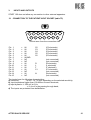
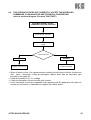
CARDIETTE ®
SERVICE MANUAL
START 100
Rev. 01
Data:
AFTER SALES SERVICE
28 May 1999
Code Nr. 66500092
1
INDEX
Foreword and special remarks
Installation program
Register number
Aim of the manual
Reference standards
Special remarks
page
page
page
page
page
page
1.
Technical characteristics
page 7
2.
2.1
2.2
2.3
2.4
2.5
2.6
2.7
2.8
Apparatus description
Case
Battery
Mother board
Keyboard
Paper sensors board
Printer mechanical group complete with thermal head
Mechanical group of the paper driving system
Protection from defibrillation
page 9
page 9
page 9
page 9
page 11
page 11
page 11
page 11
page 11
3.
3.1
Inputs and outputs
Connection to the patient input socket
page 12
page 12
4.
4.1
4.2
4.3
Check of the safety characteristics
Required instruments
Applied voltage test
Leakage current test
pag. 13
page 13
page 13
page 14
5.
5.1
5.2
5.3
5.4
5.5
5.6
5.7
Check of the main characteristics of the electrocardiograph
Required instruments
Sensitivity test
Test of the ECG leads
Check of the paper driving system
Check of the response in frequency
Check of the power supply and battery recharge
Technical self-test
page 16
page 16
page 16
page 16
page 17
page 18
page 18
page 19
6.
Detection of the damaged circuits and analysis of the
main malfunctions
Introduction
Purpose
The apparatus does not switch on
The apparatus does not correctly accept the keyboard commands
Malfunctions during printing process
Malfunctions during paging and paper presence signalling
Malfunctions caused by defective paper driving
Illustration of the power supply voltage
page 20
6.1
6.2
6.3
6.4
6.5
6.6
6.7
6.8
AFTER SALES SERVICE
4
4
4
5
6
6
page 20
page 20
page 21
page 23
page 24
page 26
page 28
page 30
2
7.
7.1
7.2
7.3
7.4
7.5
7.6
7.7
7.8
7.9
7.10
7.11
Disassembling and reassembling the apparatus
Foreword
Opening and closing the apparatus
Disassembling the mother board
Disassembling the battery
Disassembling the keyboard
Disassembling the paper driving motor group
Disassembling the printer group
Disassembling the paper and notch sensors card
Disassembling the paper lid
Disassembling and replacing the keyboard plate
Mains fuses
page 31
page 31
page 31
page 31
page 32
page 33
page 33
page 33
page 33
page 34
page 34
page 34
8
8.1
8.2
8.3
Calibrations
General information
Calibrating the sensitivity of paper and notch presence sensors
Calibrating the paper speed
page 35
page 35
page 36
page 36
9.
9.1
9.2
9.3
9.4
General directions for maintenance
Foreword
Messages
Inspection schedule
Cleaning the thermal head
page 37
page 37
page 37
page 38
page 39
10. List of spare parts
10.1 General information
APPENDIX A
Procedures for handling and storing electronic components sensitive
to electrostatic discharges (ESD)
Ilustrated tables
AFTER SALES SERVICE
page 40
page 40
page 45
page 47
3
FOREWORD AND SPECIAL REMARKS
This apparatus is a multilingual, class I (first) and CF type portable electrocardiograph with
3/6 printing channels and dual power supply (mains/battery).
The apparatus uses 130 mm wide rolls of thermosensitive paper, provided with grid.
It is supplied in two different models:
START 100 P
110 ÷ 120 Vac
220 ÷ 240 Vac
This model, in addition to recording the ECG, grants the possibility of:
− calculating the main electrocardiographic parameters with either brief or extended
report;
− recording in both manual and automatic mode, with copy possibility in printing mode 3
and/or 6 channels;
− selecting the language (Italian - English - German - French -Spanish - Russian);
− selecting the 50 -55 - 60 Hz filters;
− automatically numbering the pages by either terns or six lines groups, 1 or 2;
− inserting the user name.
START 100 H
110 ÷ 120 Vac
220 ÷ 240 Vac
This model differs from the previous one in that it features the implementation of the
interpreting program instead of the parameters calculation.
INSTALLATION PROGRAM
The access to the programming menus can be achieved in two steps.
The first one takes place by depressing the STOP key within 3 seconds after switching the
apparatus on. If the procedure has been correctly performed, all the leds relevant to the
velocity, amplitude and filters keys will blink.
In such condition the AUTO - STOP - SPEED keys shall be depressed in sequence.
The menu activation is very clearly guided on the print-outs.
For more detailed information, please refer to the “installation instructions”.
REGISTER NUMBER
The label with the apparatus identification data is placed on the movable bottom (Table
T3).
The label is subdivided into three parts:
1 - The upper part gives the seller’s data and the apparatus trademark.
2-
The middle part gives:
The model
__________
the characteristics of the power supply in Volt __________
The code number __________
the frequency in Hz.
___________
The serial number __________
the absorption in Amperes ___________
CE mark
__________
AFTER SALES SERVICE
4
3-
The lower part gives:
the language (or langages)
___________
the manufacturer’s identification data ___________
NOTE:
Always use the series code and the apparatus code when communicating with the Seller
or with the Assistance Service.
CE MARKING
The CE marking identification label is placed on the movable bottom and defines the type
of apparatus conformity.
CE Marking only
CE
it defines conformity to European Community Directive 89/336 relative to electromagnetic
compatibility.
CE Marking 0470
CE 0470
it defines conformity to European Community Directive 93/42 relative to the safety of
medical devices.
The number 0470 indicates the homology number of the Nemko Certified Body.
AIM OF THE MANUAL
The aim of this manual is the following:
a) to give a description of how the unit operates;
b) to give a description of the procedures necessary to carry out a complete test of the
apparatus;
c) to give a description of the procedures necessary to carry out the safety tests
according to the IEC safety regulations;
d) to identify and isolate blocks of operational breakdowns;
e) to describe the maintenance interventions necessary for a correct and long-lasting
operation of the apparatus;
f) to supply a list of spare parts.
AFTER SALES SERVICE
5
REFERENCE STANDARDS
The safety characteristics of the electromedical class apparatus are in accordance with the
regulations:
EN 60601-1: (1990)
General regulations for the safety of electromedical equipments
EN 60601-1: (1990/A1-1993)
EN 60601-1: (1990/A2-1995)
EN 60601-1-2: (1993)
Regulations about the electromagnetic compatibility of
electromedical equipments
IEC 601-2-25: (1993)
Special safety regulations for electrocardiographs
IEC 62D(CO)6: (1978)
Special regulations about the performance of the
electrocardiographs
SPECIAL REMARKS
a) Please remember that, by following the instructions outlined in this manual, the
apparatus and its accessories will be correctly and efficiently maintained and
consequently will be safer and will last longer.
b) Please remember that this service manual is only addressed to technically competent
persons.
c) Please remember that all the instrumentation described or indicated in this service
manual is necessary to correctly carry out tests, calibrations and controls of the safety
characteristics of the apparatus.
d) Please remember that whenever the apparatus is opened for inspection or assistance,
a complete control of the safety characteristics, as described in chapter 5, must be
carried out before the apparatus is returned.
e) Please remember that this apparatus has been designed using CMOS technology.
Most of the electronic components belongs to the ELECTROSTATIC SENSITIVE
DEVICES (ESD).family.
Therefore, it is necessary to follow specific working procedures.
Appendix A describes the special procedures required in the treatment of electrostatic
sensitive devices (ESD.).
The manufacturer refuses all responsibility for any damage undergone by the
apparatus caused by inadequate or non existent working procedure necessary
in treating with ESD devices
NOTE:
Transportation and packaging of the apparatus not in its original packaging or
an incorrectly packaged apparatus, frees the manufacturers of any
responsibility with regard to damages to the apparatus and its accessories thus
resulting in the annulment of the warranty.
f) H&C MEDICAL DEVICES S.p.A. reserves to itself the right to modify at any time,
and without any advance notice, the product or this manual.
g) Before starting the assistance service, please ready the entire content of this
manual.
AFTER SALES SERVICE
6
1.
TECHNICAL CHARACTERISTICS
Power supply from mains
Max input
Mains power supply protection
Built-in power supply
Battery protection
Applied part
Protection from defibrillation
Input dynamics
Input impedance
Common rejection
Frequency response
Time constant
Acquisition
Leads
Signal memory
Sensitivity:
manual
automatic
Printing system
Printing channels
Paper driving speed
Thermo-sensitive paper
Filters
Keyboard
Led
Interpreting Program
(START 100 H)
Parameters calculation
(START 100 P)
Operating mode
Usage mode
Autonomy
Recharging time
Caovering protection degree
AFTER SALES SERVICE
Class I (first)
110..120 V~ ± 10% 50..60 Hz
220..240 V~ ± 10% 50..60 Hz
0.28 A at 110 ÷ 120V~ ± 10%
014 A at 220 ÷ 240V~ ± 10%
T 0.315 A - 250 V (5x20 mm.) fuse at 110..120 V~
T 0.16 A - 250 V (5 x 20 mm) fuse at 220..240 V~
Built-in lead rechargeable battery 12V 0.8 Ah
T 2 A - 250V (5x20mm) fuse
CF type
Inside the apparatus
± 300 mV @ 0 Hz
± 6.4 mV in the passing through band
> 100 MΩ on each electrode
95 dB
0.05..150 Hz (-3dB) without filters
> 3.3 sec
12 bits
1000 samples/sec/printing channel and filters
500 samples /sec/channel during calculation phase
3.125 µV/bit resolution
12 STANDARD leads, out of which:
8 acquired - 4 reconstructed (III - aVR - aVL - aVF)
10 s for each lead in self-isochronous mode
5 - 10 - 20 mm/mV ± 5%
3 channels printing
10 mm/mV for 0.3 ÷ 3 mV signals
5 mm/mV for signals > 3 mV
20 mm/mV for signals < 0.3 mV
6 channels printing
10 mm/mV for 0.15 ÷ 1.5 mV signals
5 mm/mV for signals > 1.5 mV
20 mm/mV for signals < 0.15 mV
Thermal printing unit 8 dot/mm
Printing useful height 108 mm
3-6
5 mm/s ± 10% 25 - 50 mm/s ± 5%
DOT-CARD® 130 mm in 25 metres rolls
Mains disturbancies: modified 50 - 55 - 60 Hz notch digital
Anti drift : 0.5 Hz, pass high and linear phase digital filter
Membrane type, with 8 functional and numerical keys
9 Function indicators
HES ECG program developed by
Medizinische Hochschule Hannover - Germany
Developed by “lstituto di Fisiologia Clinica (C.N.R.)” in Pisa
filter
Italy
Manual (real time acquisition)
Automatic (isochronous)
Continuous operation
Built-in battery: 30 minutes in the 3 channel mode
10 mm/mV
25 mm/sec.
10 Hz p.v.
Built-in battery: 4 h 80%
12 h
100%
IP20
7
Environmental conditions:
operation
Transport and storage
Dimensions
Weight
Compliance with standards
Ambient temperature: +10°C to +40°C
Relative humidity: 25% to 95% (without condensation)
Atmospheric pressure: 700 hPa to 1060 hPa
Ambient temperature: -10°C to +40°C
Relative humidity: 10% to 95% (without condensation)
Atmospheric pressure :500 hPa to 1060 hPa
247 x 69 x 262 mm. (width x height x depth)
2.4 Kg
EN 60601-1: (1990)
EN 60601-1: (1990/A1-1993)
EN 60601-1: (1990/A2-1995)
General standards for the electromedical equipment safety
EN 60601-1-2: (1993)
Standards related to the electromagnetic
compatibility of electromedical equipment
IEC 601-2-25: (1993)
Special safety standards for electrocardiographs
IEC 62D(CO)6: (1978)
Special performance standards for electrocardiographs
NOTE REGARDING THE PROTECTION:
The maximum applicable voltage to inputs and outputs is the maximum value causing no
damage to the apparatus.
AFTER SALES SERVICE
8
2.
APPARATUS DESCRIPTION
The apparatus consists of the following main components:
− case, internally painted with conductive and shielding paint, complete with paper lid,
plate, keyboard and serigraphs;
− sealed lead battery;
− main electronic card, hereinafter called “mother board”;
− keyboard card;
− paper sensors card;
− printer mechanical group complete with thermal head;
− mechanical group of the paper driving device
2.1
CASE
The case consists of two parts:
− the upper housing, made of polycarbonate Lexan 940, colour RAL 7035;
− the lower housing, made of ABS, colour RAL 7025.
Both parts are internally painted with conductive and shielding paint. Such lining is highly
conductive and works as a shielding both against the radio disturbances generated by the
apparatus and those externally produced, which could cause malfunctions.
The fastening columns of cards and mechanical components, as well as the PVC
insulating plates, are an integral part of the case.
SAFETY NOTE
The mentioned insulations are strictly required to guarantee the safety features of the
apparatus. If they are removed during an inspection or repair of the apparatus, they must
be exactly restored as foreseen by the design.
2.2
BATTERY
The battery is a lead sealed type accumulator having the following characteristics:
− voltage:
12 V;
− capacity: 0.8 Ah;
− dimensions:
96 x 62 x 25 mm (width - depth - height);
− weight:
350 g;
− recommended make: FIAMM-GS FG20086.
SAFETY NOTE
The battery can only be replaced with the recommended type or an equivalent one, as to
both the electic characteristics and the mechanical ones.
2.3
MOTHER BOARD
The mother board is a multilayer printed circuit card (six layers) in “fine-line” technology for
the assembly of SMD components (Surface Mounting Devices).
It houses most of the apparatus electronic circuits and may be divided in the following
sections, with reference to the electrical block diagram file name: Blok - 100.
AFTER SALES SERVICE
9
2.3.1 POWER SUPPLY FROM MAINS
The power supply from mains is a Class I type, therefore it assures the apparatus
electrical safety only if the protection earthing (yellow/green wire of the power supply
cable) is connected to a system realized in compliance with the laws in force.
The section consists of the following parts:
− separable three-wire mains cable;
− three-pin mains plug with built-in extractable fuses (table T 2);
− protection devices (VDR and PTC) and disturbances filtering devices;
− mains transformer complying with medical standards, code ET 69701082 (table T 6);
− rectifying, filtering and voltage adjustment circuits with current limiter for the recharge of
the built-in battery. Such circuits do not allow operating the apparatus without the
battery;
− connection socket with earthing functions and equipotential connection (table T 2).
The equipotential connection must be carried out according to the instructions and using
the materials listed hereunder.
Required material:
• cylindrical head, M5X10 mm type screw;
• 5 mm internal diameter washer;
• 5 mm internal diameter cable terminal;
• wire with overall resistance lower than 0.1 Ohm and 1.5 cm2 minimum section.
Instructions:
• prepare and solder the wire to the cable terminal;
• insert the washer and the cable terminal in the screw;
• fix and adequately tighten the screw in the equipotential threaded bushing.
SAFETY NOTE
The replacement of the components belonging to the mains power supply section may
only be carried out using identical components to the original ones, homologated by the
manufacturer, or else the safety features of the apparatus will be lost.
2.3.2. POWER SUPPLY TO INTERMEDIATE CIRCUITS
This section consists of a DC/DC converter and a high frequency transformer generating
the following voltages:
• 5 V to supply the control logic;
• 24 V to supply the printer thermal head;
• ± 5 V to supply the insulated part.
2.3.3. INTERMEDIATE CIRCUITS FOR CONTROL AND INTERFACING
This section includes the microprocessor system controlling the operation of the whole
apparatus and the external interfaces of the mother board, such as the keyboard and the
serial interface RS232, the analog inputs and outputs, the remote control and the auxiliary
power supply, if provided.
AFTER SALES SERVICE
10
SAFETY NOTE
The connection to the intermediate circuits, for instance through the serial interface
RS232, may be realized only and exclusively towards other medical apparatus, according
to IEC 601-1-1 standard relating to the medical systems safety. Should any doubt exist
about the compliance to the medical standards of the apparatus connected to the
intermediate circuits (e.g. a Personal Computer), make use of a galvanic de-coupling
device, that may be provided by request.
2.3.4. INSULATED PREAMPLIFIER
This section consists of a 12 channels ECG preamplifier with active control of the
reference electrode, complete with protection from the effects of defibrillation and 12 bit
analog/digital conversion circuit.
The galvanic de-coupling is performed by means of a guard zone on the printed circuit (4
mm minimum insulation) and photo-couplers (2500V rms minimum for 1 minute
insulation).
SAFETY NOTE
We strongly advise against any intervention on the components assuring the patient
insulation, such as the photo-couplers and the insulation transformer of the DC/DC
converter generating the intermediate and insulated power supplies. In case of failure
replace the mother board.
2.4
KEYBOARD
This card houses only the keys and leds required for the operation of the apparatus.
2.5
PAPER SENSORS BOARD
This card houses the sensors signalling the paper presence and the paging black notch.
2.6
PRINTER MECHANICAL GROUP COMPLETE WITH THERMAL HEAD
This group consists of the supporting plate for the printer thermal head and the mechanical
components required for its correct positioning.
A complete sparee group is provided.
2.7
MECHANICAL GROUP OF THE PAPER DRIVING SYSTEM
The group consists of the driving motor complete with support and gears.
A complete spare group is provided.
2.8
PROTECTION FROM DEFIBRILLATION
The apparatus has a built-in protection from the defibrillator discharges.
Therefore this apparatus allows the use of patient cables not protected from defibrillation
and supplied by the manufacturer.
AFTER SALES SERVICE
11
3.
INPUTS AND OUTPUTS
START 100 does not allow any connection to other external apparatus.
3.1 CONNECTION TO THE PATIENT INPUT SOCKET (table T2)
7
8
15
14
4
5
6
13
12
3
11
1
2
10
9
Socket seen from the connection side
Pin 1
Pin 2
Pin 3
Pin 4
Pin 5
Pin 6
Pin 7
Pin 8
Pin 9
Pin 10
Pin 11
Pin 12
Pin 13
Pin 14
Pin 15
=
=
=
=
=
=
=
=
=
=
=
=
=
=
=
IN
IN
IN
IN
IN
IAGND
NC
NC
IN
IN
IN
IN
NC
IN
NC
C2
C3
C4
C5
C6
R
L
F
C1
N
(C2 electrode)
(C3 electrode)
(C4 electrode)
(C5 electrode)
(C6 electrode)
(not connected)
(not connected)
(R electrode)
(L electrode)
(F electrode)
(C1 electrode)
(not connected)
(N electrode)
(not connected)
The inputs have the following characteristics:
a) Sensitivity:
1 mV/5 - 10 - 20 mm depending on the selected sensitivity;
b) Input impedance higher than 100 MOhm for each electrode;
c) Input dynamic:+/- 300 mV.at 0 Hz.
+/- 6.4 mV in the passing through band;
d) The inputs are protected from defibrillation.
AFTER SALES SERVICE
12
4. SAFETY CHARACTERISTICS CONTROL
The safety regulation expects two important tests:
a) The applied voltage test:
it verifies the insulating efficiency of the power supply circuits and those relative to the
patient connections.
b) The leakage current test:
it measures the value of the leakage currents in relation to patient safety.
NOTE:
All safety tests should be performed according to IEC 601-1 regulations(paragraphs 1920).
4.1 NECESSARY INSTRUMENTS
a) Insulating strength analyser:
model "U28 M" Elektrotechn. Laboratorium D - 7015 Korntal Germany or its
equivalent;
b) Leakage current analyser:
model “AMPLAID ST 10“ - Amplifon Division S.p.A. Italy, or
model METRON QA 80” Electrical Safety Analyser, or
model “BIO-TEK 601-PRO” Amplisim Division srl - Italy or its equivalents
4.2 APPLIED VOLTAGE TEST
The test should be carried out in a suitable location in accordance with safety regulations
by using the instrument 4.1 a).
This test must be carried out only in those apparatuses in which components with special
insulating characteristics have been substituted:
a) power supply transformers;
b) transformer on the TR1 voltage converter;
c) optoinsulators: FC1...FC7 of the mother board;
d) entire mother board.
4.2.1 INSULATING TEST TOWARDS MAINS POWER SUPPLY
Perform this test with the mains switch inserted (Table T2).
a) Apply the test voltage between the pins with the exclusion of the central pin in the
apparatus mains plug (Table T2) and the equipotential outlet which is connected to the
frame (ground) of the apparatus (Table T2).
b) How the performance test is carried out:
(class I electrocardiograph (first).
Apply for 10 seconds a voltage equal to 0.750 KVac, then raise it to 1.5 KVac and hold it
at this value for 1 minute.
AFTER SALES SERVICE
13
4.2.2 DECOUPLING TRANSFORMER AND OPTOINSULATOR TEST.
(CF type electrocardiograph defined by this symbol
)
Perform this test with the apparatus turned off.
a) Apply the test voltage between all the Pins of the patient input outlet connector (Table
T2) and the equipotential outlet (Table T2);
b) Apply for 10 seconds a voltage equal to 1.25KVac then raise it to 2.5KVac and hold it
at this value for 1 minute.
4.2.3 IN BOTH TESTS (4.2.1 - 4.2.2)
Verify that during the test there are neither superficial nor destructive discharges.
Moderate discharges due to the back effect can be ignored, as long as they stop when the
test voltage is temporarily lowered to a lower value, which nevertheless must remain
greater than the reference voltage U (250V), as long as the discharges do not result in test
voltage drops.
4.3 LEAKAGE CURRENT TEST
THIS TEST TO BE MADE AFTER EACH OPENING FOR INSPECTION
AND/OR REPAIR USING TOOL 4.1 B AND IN ANY CASE EVERY TWO
YEAR PERIOD.
Proceed as follows:
4.3.1 Connect the electrocardiograph to the measuring instrument according to the
instructions given in its user’s manual and remember that:
a) The leakage current towards ground, is measured between the mains power supply
circuits and the ground point of the equipotential outlet (Table T2).
b) The leakage current towards the case, is measured between the mains power supply
circuits(Table T2), the equipotential outlet (Table T2) and a metallic sheet not greater
than 20 x 10 cm in size which should be pressed against the case, if composed of
insulating material.
c) The leakage current in the patient, is measured between the mains (Table T2) and the
applied part (Table T2).
The same patient cable can be used for the connection with the applied part.
d) The leakage current in the patient with mains voltage directly on the applied part (first
fault condition), is measured between the equipotential connection (Table T2) and the
applied part (Table T2).
e) The auxiliary current in the patient, is measured individually on each electrode (with
the exclusion of the black one) with respect to all the other electrodes connected
together.
4.3.2 Program the instrument according to the electrocardiograph type (CF) and class I
(first).
4.3.3 Perform the measurement according to the instructions given in the user’s manual of
the instrument itself and verify that the values of the leakage currents measured are
less than or equal to those reported in Table IV.
AFTER SALES SERVICE
14
IEC REGULATIONS 60601-1
60601 - 2 - 25
(1990)
(1993)
Table IV
Permanent admissible values for the leakage currents and for the auxiliary currents in the
patient in mA.
Current path
Leakage current towards ground
Leakage current in the case
Leakage current in the patient
Leakage current in the patient with
mains voltage in the applied part
Auxiliary current in the patient
(+) N.C. = Usual condition
(++) S.F.C. = First fault condition
AFTER SALES SERVICE
CF type
N.C. (+)
0.5
0.1
0.01
----0.01
S.F.C.(++)
1
0.5
0.05
0.05
0.05
15
5.
CONTROL OF THE APPARATUS MAIN TECHNICAL CHARACTERISTICS
5.1 REQUIRED INSTRUMENTS:
The instrumentation required includes:
a) mV impulse generator with the following minimum characteristics:
- impulse width: 1mV ± 3%;
- impulse repetition rate: 1 Hz;
- tolerance rate: ± 1%;
- max. impulse rise time: 1 ms
b) low frequency sinusoidal wave generator.
c) accessory ECG simulator
5.2 SENSITIVITY TEST
Proceed as follows:
a) prearrange the apparatus for the recording of 3 signals with leads V1...V3 and
sensitivity of 20 mm/mV.;
b) connect the patient cable to the apparatus;
c) connect the C1...C6 terminals of the patient cable connected to the apparatus to the
positive pole of the instrument 5.1 a);
d) connect all the other terminals of the cable to the negative pole of the instrument
5.1 a);
e) carry out a recording for a few seconds;
f) check that the width of the recorded signal is equal to 20mm. ± 5% over all the
channels (Reference: IEC 62 D(CO)6 Regulations);
g) repeat the test with leads V4...V6.
5.3 ECG LEAD TEST
Proceed as follows:
a) turn on the apparatus;
b) connect the patient cable to the apparatus;
c) connect the patient cable red terminal to the positive pole of the instrument 5.1 a), and
the remaining ones to the negative pole.
Start recording and check that the signal width in mm and its polarity (positive or
negative) agrees with the values given in Table 5.3.
d) repeat the measurement in succession with all the remaining active terminals G - V - C1
- C2 - C3 - C4 - C5 - C6 of the patient cable in the same manner as in c) and check that
the values correspond to those reported in Table 5.3.
AFTER SALES SERVICE
16
LEADS AND PATIENT CABLE TEST
CONNECTIONS FOR TESTING
INSTRUMENT PART
PATIENT CABLE LINK
Connector
Patient cable terminal
N. 1 Terminal on positive (black excepted)
+
- 1
2 3 4 5 6 7 8 9 10
N. 4 Terminals on negative with 5 wires cable
Square wave signal:
1 Hz ± 1%
N. 9 Terminals on negative with 10 wires cable
Electrocardiograph : 1mV/10 mm amlificaiton
1 mVpp ± 3%
recorded signal in mm 5%
TABLE OF VALUES
Terminal LEADS AND PULSE VALUES
on
I°
II°
III°
aVR
aVL
positive mm
mm
mm
mm
mm
R
G
V
C1
C2
C3
C4
C5
C6
- 10
+ 10
0
0
0
0
0
0
0
- 10
0
+ 10
0
0
0
0
0
0
0
- 10
+ 10
0
0
0
0
0
0
+ 10
-5
-5
0
0
0
0
0
0
-5
+ 10
-5
0
0
0
0
0
0
aVF
mm
V1
mm
-5
-5
+ 10
0
0
0
0
0
0
V2
mm
- 3,3
- 3,3
- 3,3
+ 10
0
0
0
0
0
V3
mm
- 3,3
- 3,3
- 3,3
0
+ 10
0
0
0
0
- 3,3
- 3,3
- 3,3
0
0
+ 10
0
0
0
V4
mm
- 3,3
- 3,3
- 3,3
0
0
0
+ 10
0
0
V5
mm
- 3,3
- 3,3
- 3,3
0
0
0
0
+ 10
0
V6
mm
- 3,3
- 3,3
- 3,3
0
0
0
0
0
+ 10
Table 5.3
5.4
CHECK OF THE PAPER DRIVING SYSTEM
Proceed in the following manner:
a) turn on the apparatus and connect the patient cable;
b) connect the C1...C6 terminals of the patient cable to the positive pole of the instrument
5.1 a);
c) all the other terminals should be connected to the negative pole of the instrument 5.1
a);
d) using the instrument with a 1Hz square wave of 1 mVpp width;
e) record the signal on the leads V1...V6;
f) measure the length of the wave period recorded on the paper.
It should come out to be:
Period = 25 mm ± 5% for 25 mm/s speed;
Period = 50 mm ± 5% for 50 mm/s speed;
Period = 5 mm ± 10% for 5 mm/s speed.
AFTER SALES SERVICE
17
NOTE:
It’s not necessary to calibrate the paper feed rate, because this control is automatically
managed by the microprocessor.
5.5 CHECK OF THE FREQUENCY RESPONSE
Proceed as follows:
a) turn on the apparatus and connect the patient cable;
b) connect the C1...C6 terminals of the patient cable to the positive pole of the instrument
5.1 b);
c) all the other connectors should be connected to the negative pole of the instrument
5.1 b);
d) prearrange the generator on a 10Hz sinusoidal wave with about 1 mVpp width
e) select V1...V6 leads and 10 mm/mV sensitivity;
f) carry out a recording and set the generator width in such a way as to obtain a 10 mm
swing in the recorded signal;
h) vary the generator frequency from 0.5Hz to 100Hz keeping the width constant;
g) check that the frequency response is in agreement with Table 5.5.
FILTERS
none
none
none
35Hz
35Hz
35Hz
35Hz
50Hz (60)
50Hz (60)
50Hz (60)
FREQUENCY PARAMETERS (Hz)
0.5-60
75
100
0.5-20
30
40
70
0.5-20
50 (60)
60-100 (70-100)
WIDTH (mm)
min. 9.0 - max. 10.5
min. 7.0 - max 10.5
max. 9.0
min. 9.0 - max. 10.5
min. 7.0
max. 7.2
min. 3.0 - max. 4.5
min. 8.0 - max. 10.0
max. 0.5
max. 2.0
TABLE 5.5
5.6
CHECK OF POWER SUPPLY AND BATTERY RECHARGE
Proceed as follows:
a) open the apparatus as mentioned in chapter 7.2, supply it through the mains, paying
attention to keep the live parts duly insulated;
b) checking the supplied voltage:
- replace the battery with a 1 KOhm, 0.25 W resistor and measure the voltage at its
terminals: it must correspond to 13,65 V ± 5%;
c) checking the supplied current:
- replace the battery with a load ranging from 0 Ohm to 30 Ohm 15 W and measure
the supplied voltage and current;
- check that with a 12 Vdc voltage the current is 0.9 A ± 10%;
d) check the discharged battery indication:
- still meeting the polarities, replace the battery with a power supply capable of
supplying 5A with a voltage ranging from 0 to 15 Vdc;
- switch the apparatus on and check that the yellow led indicating a “discharged
battery” condition lights up with 10.75Vdc ±2%.
AFTER SALES SERVICE
18
5.7
TECHNICAL SELF-TEST
The self-test function can be activated by depressing the COPY key within 3 seconds from
the apparatus start-up.
The apparatus prints out a triangular wave to check the efficiency or detect failed dots of
the printer head, if any, the alphanumeric types available in the memory and some ‘step’
signals to check the 3 velocities.
Then it prints out a page reporting the result of the RAM test, the total number of pages
printed so far, the code and the software revision and a warning to remind proceeding with
the keys test.
Depressing the keys in sequence lights the related led up as follows:
key
MAN
AUTO
COPY
VELOCITY
AMPLIFICATION
FILTERS
STOP
led
50 mm/sec.
25 mm/sec.C
10 mm/mV
5 mm/mV
50 Hz filter
ADF filter
saturation
This configuration can be abandoned by depressing the STOP key, that lights up the
orange led and brings the apparatus back to the normal “ready for use” status.
AFTER SALES SERVICE
19
6.
DETECTION OF THE DAMAGED CIRCUITS AND ANALYSIS OF THE MAIN
MALFUNCTIONS
6.1
INTRODUCTION
After the introduction of SMT technology (Surface Mounting Technology) and of “fine line”
multilayer printed circuits, singling out and repairing the damage have become extremely
difficult even with adequate equipment and tools.
Therefore it is advisable not to attempt the repair of single cards, whereas their
replacement is suggested. Quite often an inadequate intervention prevents any possibility
of further repair once the apparatus is sent back to the factory.
6.2
PURPOSE
This chapter provides the repairman with useful information in order to single out the failed
card and/or group.
For that purpose, the analysis of the possible malfunctions or failures is synthesized in flow
diagrams, and subsequently developed in detail according to the circuit logic reported in
the general block diagram of the apparatus and mother board.
AFTER SALES SERVICE
20
6.3
THE APPARATUS DOES NOT SWITCH ON, FLOW ANALYSIS AND TECHNICAL
DESCRIPTION
(refer to electrical diagram, file name ACCU 12 V)
EQUIPMENT DOESN'T
SWITCH ON
WITHOUT
MAINS
WITH MAINS
Check the T 2 A battery
fuse
GOOD
BROKEN
Verify current comsumption
max 1,8 A d.c.
Verify battery
operation
Verify fuse burnout cause
GOOD
BROKEN
Remove fuse burnout cause
Verify the 12 V power
supply circuit
Replace battery
Replace fuse
BROKEN
Verify ON/OFF circuit
BROKEN
Replace mother board
AFTER SALES SERVICE
21
6.3.1 Protective fuse of the battery type T 2 A missing or melted
• Check that the power absorbed by the apparatus is lower than 1.8 A d.c.. If the value is
higher, search for the cause.
• Once the cause has been eliminated, replace the fuse with an equivalent type.
6.3.2 Damaged battery
• The battery emitted some acid
• It is swallen
• Cannot be recharged
Replace it with an equivalent one as to type, voltage and capacity.
6.3.3 Battery check
To check the efficiency of a battery having plate data 12 V 0.7 - 0.8 Ah proceed as
follows:
• Take it out from the case as described in chapter 7.4.
• Power it with an external 13.65 V voltage power supply, checking whether it absorbs
any current. Such current depends on the charge conditions.
• After recharging it for 15 hours, discharge it through a resistance with a 0.7 - 0.8 Ah
current.
If the voltage remains higher than 11 Volt for about 30 minutes the battery may be still
considered to be efficient, if not its charging capacity is very limited and its replacement
is advisable.
6.3.4 Battery recharge failed due to the 12 V power supply, check:
• Refer to chapter 5.6
• Supply circuit from mains
• Transformer 230/22 V - 115/22 V
• Outlet bridge 30 Vdc ± 5% on pin 4 of the switching IC29 controller.
• Presence of about 14 V ± 0.5 measured on R4, anode side of diode D54. The correct
value of such voltage indicates a regular operation of the switching IC29 controller.
• ON/OFF circuit, check whether depressing the ON/OFF key of the keyboard, with the
stand-by switch closed, a 13.65 V voltage appear on Q8 drain. If not, the mother board
is to be considered damaged.
AFTER SALES SERVICE
22
6.4
THE APPARATUS DOES NOT CORRECTLY ACCEPT THE KEYBOARD
COMMANDS, FLOW ANALYSIS AND TECHNICAL DESCRIPTION
(refer to electrical diagram, file name TAS START)
EQUIPMENT DOESN'T ACCEPT
COMMANDS FROM THE KEYBOARD
Check flat and connector
Check +5 V d.c. power supply
voltage
Check keyboard
GOOD
BROKEN
Replace mother board
Replace keyboard
• When a failure occurs, It is a good practice checking the efficiency of all the connections
(flat - wires - terminals); if they are damaged, replace them with an equivalent type
provided in the spare kit.
• Check the presence of + 5 V voltage
• Check the operation of keys and leds with a tester.
• If the mentioned circuits are repairable and operating and the apparatus still does not
accept any command, it is advisable to replace the mother board.
AFTER SALES SERVICE
23
6.5
MALFUNCTIONS DURING PRINTING PROCESS, FLOW ANALYSIS AND
TECHNICAL DESCRIPTION
(refer to electrical diagram, file name POW-SUP and XILINX)
PRINTOUT
ABNORMAL
PRINTOUT
NO PRINTOUT
Too heavy
Irregular or weak
Check + 24 V d.c. power
supply voltage
Clean thermal head
(chapter 9.4)
NOT CORRECT
CORRECT
Defective mother board
Check connections
Check connection flat
Check + 24 V d.c. power
supply voltage
Check recording
signals
CORRECT
Replace mother board
CORRECT
NOT CORRECT
Replace printer
Defective mother board
Check + 24 V d.c. power
supply voltage and
recordings signals
CORRECT
Check 12 V d.c. power
supply voltage
Replace mother board
CORRECT
Check mechanical
assembly
Check paper
AFTER SALES SERVICE
24
6.5.1 There is no print-out
• Check the efficiency of the connection between thermal head and mother board
(flexstrip).
• Check, while the printing process is active, the power supply to the thermal head Vset,
25 V d.c. ± 1 measured on either drain Q7 or pin 1 of J4 (depending on the type of
signal being printed) during the printing process.
• Check the existence of either an electrocardiographic or instrumental signal.
• If above points check, activate the printing function of the apparatus and check on
connector J4:
a) The presence of a 1.5 Mhz clock on pin 5, see Fig. 1;
b) The presence of logic signals on the lines BDIP on pin 7 (data) and -LAPT on pin 6,
see Fig. 1;
c) The presence of a square strobe wave signal on pin 4 with a frequency of 1 Khz, see
Fig. 1.
If there is still no print-out when such signals are present as per Figure 1, replace the
thermal head group.
If, on the contrary, the signals do not correspond to Figures 1, the failure is located in
the mother board which needs being replaced.
6.5.2 Anomalous print-out
Electrical check
• If the prin-out is too intense at any velocity, check that Vset on pin 1 of J4 is not higher
than 28 Vdc (maximum supply voltage of the thermal head); if Vset is higher, the control
circuit is damaged (see Q2 - Q3 - Q4 - Q7).
• If the duration of the strobe impulse on pin 4 of J4 is higher than approximately 700
msec., see Fig. 2, the mother board is damaged and needs being replaced.
• If the apparatus regularly operates and the print-out disappears, check the correct
operation of the battery.
Mechanical check
• If the pressure among the thermal head, paper and driving platen is insufficient, check
fixing of the printer on the case and pay attention, when tightening the two screws, to
keep the thermal head group well and homogeneously forward pressed against the box
containing the paper. If the printer is fixed in an inclined position the writing is irregular.
• Check that the paper driving platen does not rotate eccentrically; if this happens,
replace the paper lid.
AFTER SALES SERVICE
25
6.6
MALFUNCTIONS DURING PAGING AND PAPER PRESENCE SIGNALLING,
FLOW ANALYSIS AND TECHNICAL DESCRIPTION
(refer to electrical diagram, file name M-SPEED)
PAPER PAGING AND
PAPER PRESENCE
No indication of end of paper,
no automatic stop when end
of paper
Not correct automatic paging,
no printout in AUTO Mode
Check paper sensor
Check paper sensor
GOOD
GOOD
Defective mother board
Check paper sensor system
Replace mother board
GOOD
Defective mother board
Replace mother board
AFTER SALES SERVICE
26
6.6.1 The failed control of “paper over” condition may depend on:
• FC1 sensor is dirty, clean with a cloth the slide above it.
• Faulty connection between keyboard card and mother board. Check the flexstrip.
• The calibration voltage of the sensor is not correct as per chapter 8.2.
• Damaged sensor. Replace the sensors card as per chapter 7.8.
• If the above conditions do not apply, the mother board is damaged.
6.6.2 The failed control of the black notch on the paper and the related
malfunctions in automatic mode may depend on:
• FC2 sensor is dirty, clean with a cloth the slide above it.
• Faulty connection between keyboard card and mother board. Check the flexstrip.
• The calibration voltage of the sensor is not correct as per chapter 8.2.
• Damaged sensor. Replace the sensors card as per chapter 7.8.
• If the above conditions do not apply, the mother board is damaged.
AFTER SALES SERVICE
27
6.7
MALFUNCTIONS CAUSED BY DEFECTIVE PAPER DRIVING, FLOW ANALYSIS
AND TECHNICAL DESCRIPTION
(refer to electrical diagram, file name M-SPEED)
DEFECTIVE PAPER
FEED
Paper doesn't run
Paper runs irregularly
Check paper compartment lid
Check paper guid roller and
paper feed
GOOD
GOOD
Check kymograph gears
Check the presence of paper
spindle
GOOD
GOOD
Check kymograph connector
Check kymograph gears
GOOD
GOOD
Check kymograph power
supply and control circuit
Check kymograph
stroboscope sensor
GOOD
GOOD
Replace mother board
Check kymograph power
supply and control circuit
GOOD
Replace mother board
6.7.1 The paper does not run
AFTER SALES SERVICE
28
The main causes are due to:
• Paper lid badly closed, correctly insert it.
• The teeth of either the paper lid or the motor group gear are damaged (crushed),
replace either paper lid or motor group.
• Stroboscopic disc either warped or damaged, replace motor group.
• Check the connection motor - mother board, if damaged replace the kymograph.
• Check the motor power supply and control system, proceeding as follows:
With reference to the electrical diagram, file name M-SPEED:
− check the presence of 12 Vdc on the emitter of Q1;
− check the presence of 7.5 Vdc on pin 9 of IC3;
− check the logic status of the ACV - BCV controls according to the table reported in
the electrical diagram;
− if correct values are noticed, check the working condition of the stroboscopic sensor
by manually turning the stroboscopic disc and checking on IC31 the presence of a
sinusoidal/trapezoidal signal with variable frequency as per Fig. 2 (it depends on the
set velocity);
− if no signal is noticed the stroboscopic sensor is damaged, therefore replace the
kymograph. If, on the contrary, a +/- 0.6 V signal is noticed as per Fig. 2, replace the
mother board.
6.7.2 The paper runs irregularly
(refer to electrical diagram of the mother board, file name M-SPEED)
The faulty driving of paper also causes some mulfunctions during the printing process and
the notch checking process.
The main causes are due to:
• Perform all the mechanical checks described in above chapter 6.7.1.
• If the motor does not control the speed any longer and takes to spin along, then either
the stroboscopic control is missing or Q1 transistor is short-circuited.
− In the first case, check the signal on pin 1 of IC31. If the stroboscopic sensor is
damaged no signal will be noticed, therefore replace the motor group.
− In the second case, Q1 transistor is short-circuited; replace it with an equivalent one.
• If the paper velocity is irregular, check:
− The efficiency of AR3 calibration potentiometer (refer to chapter 8.3, relevant to
velocity calibration); should it show any false contact, replace either the
potentiometer itself or the mother board.
− The efficiency of the motor control circuit as described in above paragraphs 6.7.1
and 6.7.2; if the circuit is found damaged, replace the mother board.
AFTER SALES SERVICE
29
6.8
ILLUSTRATION OF THE POWER SUPPLY VOLTAGE, FLOW ANALYSIS AND
TECHNICAL DESCRIPTION
(refer to electrical diagram, file name POW-SUP and ACCU - 12 V)
CHECK OF THE POWER
SUPPLY VOLTAGES
Multivoltage power
supply
12 V d.c. battery power
supply
12 V
0,7 - 0,8 Ah
battery
+ VMB =3,6 V
for memory power
supply
Insulated circuits
Not insulated circuits
+/- 5 V for analogic circuits
+ 5 V for digital circuits
Vset = + 25 V
+5V
If detected values do not
correspond, the mother
board is defective
Replace mother board
Illustration of the functions relevant to the power supply voltages.
• The section relevant to the power supply and battery recharge has already been
illustrated in chapter 6.3.
• The voltage +VBM = 3.6 V is supplied to the static RAM’s through IC33 regulator in
order to keep the data when the apparatus is off.
• Following supply voltages are obtained from TR1 multivoltage transformer:
− + 5 V through IC90 regulator to supply the digital logic;
− + 25 V Vset to supply the thermal head illustrated in chapter 6.5;
− ± 5 Volt, respectively stabilized by IC38 - IC39, to supply the analogic circuits on the
insulated part.
− Should all of the power supplies be missing, check and/or replace the 4A F1 picofuse type SLO BLO SMD foreseen in the spare parts list.
− Should the values measured during the checks be wrong, it is advisable to replace
the mother board.
AFTER SALES SERVICE
30
7.
DISASSEMBLING AND REASSEMBLING THE APPARATUS
7.1
FOREWORD
Before opening the unit all necessary precautions shall be taken to avoid possible errors
or incorrect operating procedures.
In particular:
a) always follow the directions given in appendix A of this manual, regarding the
operating procedures, the tools needed and the precautions to be taken when working
on E.S.D. components.;
b) before reassembling the unit the required calibrations as described in chapter 8 of this
manual shall be performed;
c) before closing the apparatus it is necessary to check that all subassemblies and
connections are properly installed;
d) before closing the apparatus check the proper assembly and positioning of the
insulating plates located as follows:
- on patient input connector;
- under the mother board, stuck to the bottom of the case (table T4).
NOTE:
The safety characteristics (see chapter 4) shall be checked after every opening
and/or repairing of the apparatus, as well as before its redelivery to the client.
7.2
OPENING AND CLOSING THE APPARATUS (table T 5)
The following procedure is recommeded:
a) put the equipment on a soft working bench keeping the case removable bottom
upward; unscrew and remove the eight TSP 2.5mm x 8mm screws (table T3, ref.1);
b) lift upward and disconnect the mobile bottom of the case.
NOTE:
In case the apparatus is power supplied while open, please remind that the inside is
conductive. Therefore pay special attention to the uncovered points where the
primary mains voltage and the secondary voltage of the cards supplying circuits
exist, in order to avoid causing permanent damages.
To close the equipment again follow the above directions in the opposite direction.
7.3
DISASSEMBLING THE MOTHER BOARD (table T 5)
a) proceed as mentioned at chapter 7.2 (opening the apparatus);
b)
unscrew and remove the six M4 x 6 x 3.25 brass nuts (table T 5).
Lift the card above the paper box by 1 cm and interpose through that spacing an
insulating sheet along the whole conductive case.
Once released the card in such area, by exerting an upward pressure on the power
supply plug and the patient connector contemporaneously, lift it up again by a few
centimeters and unthread the socket of the wire connected to the battery.
After this operation it becomes possible to rotate the card itself by 180° by means of
the hinge along the paper holding box, bringing it to an horizontal position.
AFTER SALES SERVICE
31
At the end of the rotation it is advisable to lean the part overhanging from the case
on a suitable insulated rest, so as to avoid any traction on the connected cables
and flats.
Under these conditions it is already possible to perform some preliminary checks
without power supply.
c)
In order to achieve a more adequate functional position, from the position reached,
rotate the case by 90° towards the card, leaving it in a vertical rest along the paper
outlet side.
d)
In case of checks performed with mains power supply, pay particular attention not
to come into contact with live parts not insulated.
e)
To either disassemble or replace the mother board completely, disconnect as
follows:
- the flat of the keyboard card;
- the flat of the sensors card;
- the flat of the thermal head;
- the connector with the connecting wires to the motor group;
- the faston with the yellow/green wire of the printer earthing connection;
Always remember to perform all the operations, as well as handling the card, only
after earthing yourselves with a suitable protected armlet.
Remember that the inside of the case is conductive.
Remember to put the card on insulated parts, in order to avoid that residual
voltages on the condensers may discharge on components or groups of
components causing permanent damage.
e)
Proceed in the opposite direction to reassemble the mother board, paying attention
to insert the mains plug vertically in the dedicated slots, so that its fixing wings
correctly lock on the internal wall of the case.
NOTE
When the insulations and auxiliary fixing elements are not restored or restored
wrongly, the safety characteristics of the apparatus fail and the producer is released
from whatsoever responsibility.
g)
The mother board replacement requires the calibration of the paper sliding speed
and the calibration of the two paper and notch presence sensors.
7.4
DISASSEMBLING THE BATTERY (table T 6)
To replace the battery (table T 6) proceed as follows:
a) Open the equipment as mentioned at chapter 7.2;
b)
Follow the directions of chapter 7.3 points a) - b), relevant to the movement of the
card, to reach the battery.
Removing the card completely is unnecessary; if desired, proceed as per point e).
c)
Remove the two fixing rods of the battery, lifting them upwards, after unscrewing
the respective fixing screws;
d)
Install in the same position a new 12 V - 0.8 Ah lead battery, equivalent as to
dimensions and power to the original one.
e) In reverse sequence:
- reassemble and fix the two battery fixing rods;
- reposition and fix the mother board, taking care to connect it first to the battery
power socket in the correct polarity. Pay attention to correctly position the
insulating plate located on the patient connector;
- reinstall and fix the mobile bottom.
AFTER SALES SERVICE
32
7.5
DISASSEMBLING THE KEYBOARD
To disassemble the keyboard it is necessary to proceed as follows:
a) Proceed as per chapter 7.3, points a) - b) - e), to open and remove the mother board
of the apparatus.
b) Unscrew the 6 fixing screws and remove the keyboard lifting it upward.
c) Proceed in the opposite direction to reassemble the board and close the apparatus.
7.6
DISASSEMBLING THE PAPER DRIVING MOTOR GROUP (table T 6)
Proceed as follows:
a) Take off the paper lid and the paper roll of the apparatus.
b) Proceed as per chapter 7.3, points a) - b) - e), to open and remove the mother board.
c) Take off the 2 fixing screws and lift the motor group up.
d) The replacement of the motor requires calibrating the paper sliding speed.
e) Proceed in the opposite direction to reassemble the motor group and close the
apparatus.
7.7
DISASSEMBLING THE PRINTER GROUP (table T 6)
Proceed as follows:
a) Follow the directions of chapter 7.3, points a) - b) - e), to open and remove the mother
board. of the apparatus, and those of chapter 7.6 for the removal of the motor group.
b) Take off the 2 fixing screws of the printer group and remove it from its housing, paying
attention not to damege the thermel head dots with hard items.
c) Proceed in the opposite direction to install the printer group, paying particular attention
to positioning all mechanical items, such as screws, washers, etc.; besides, remember
to carry out the earthing connection under the fixing screw of the frame supporting the
thermal head with the mother board, and during the fastening keep the group forced
against the paper holding box.
d) In order to achieve a long life of the thermal head, it is advisable to exclusively use the
thermo-sensitive paper DOT-CARD®, recommended by the manufacturer, in 130 mm
high rolls. The ordering code is stamped on the bottom edge of the paper itself.
e) The thermal head is highly sensitive to electrostatic potentials; therefore the
operational procedures described in appendix A shall be followed in any case.
f) The replacement of the printing group requires no calibration.
7.8
DISASSEMBLING THE PAPER AND NOTCH SENSORS BOARD (table T 6)
Proceed as follows:
a) Follow the directions given in chapter 7.3, points a) - b) - e), to open the apparatus
and remove the mother board.
b) To remove the sensors card, force it upward with a suitable tool. The card is stuck in
its housing inside the upper case.
c) To replace the card it is necessary cleaning its housing, correctly positioning it inside
its housing, with the flat outlet facing the paper holder, and sticking it by means of an
instantaneous adhesive.
d) To close the apparatus follow the reverse operations.
e) After replacement, the sensors card requires calibration to be carried out on the
mother board.
AFTER SALES SERVICE
33
7.9
DISASSEMBLING THE PAPER LID (table T 1)
The paper lid system is a mechanical device, located in the case and accessible from the
outside, which is actuated by the apparatus motor and lets the thermo-sensitive paper
slide.
It is housed above the paper box and covers the latter entirely.
To remove this particular part, proceed as follows:
a) Exert a pressure on the dedicated release hook, located in the middle of the case front
where the paper comes out from, and extract it by inclining it upwards.
b) Disassembly ot this group is necessary before inserting a new paper roll, when
cleaning the roller and, in any case, before replacement or disassembly of the thermal
head.
c) To reassemble the device it is sufficient to let it slide into its housing, keeping the
rubber roller towards the apparatus inside and holding it lifted up from the opposite
end.
As soon as inserted, exert a slight pressure downwards on the lifted end, so as to
make it click.
NOTE:
If the roller is not clean and the paper lid is either badly inserted or badly fixed, the
paper driving will be difficult and an apparatus malfunction will occur.
7.10 DISASSEMBLING AND REPLACING THE KEYBOARD MEMBRANE (table T 1)
The keyboard membrane is an elastic membrane located above the keyboard card which
allows depressing the control keys of the latter.
This self-adhesive plate is stuck on the front side of the apparatus.
To replace it in case of wear, lift it up on one corner by means of a thin blade tool and tear
it away from the case.
If any adhesive remains on the case, remove it using the finger-tips.
To install a new membrane, centre its corners inside the housing and exert a slight
pressure on the whole surface.
7.11 MAINS FUSES
The mains fuses can be reached from the outside as they are positioned below the power
supply plug on the rear part of the apparatus (table T2).
In order to replace them, exert a pressure on the two plastic wings of its container using a
pair of tweezers. The protection fuses are T 0.16 A with 220 - 240V~ power supply and T
0.315 A with 110 - 120 V~ power supply.
NOTE:
Use standard fuses. Those selected by the manufacturer are the recommended ones (see
the spare parts list, chapter 10).
NOTE:
FUSES MELTING MAY BE DUE TO EXCESSIVE POWER INPUT, AS WELL AS TO A
WRONG USE OF, OR POWER SUPPLY TO THE APPARATUS. IN ANY CASE CHECK
THE APPARATUS TO IDENTIFY THE REASON FOR SUCH FAILURE.
WARNING: ALWAYS REPLACE THE FUSES KEEPING THE MAINS CABLE
DISCONNECTED FROM THE APPARATUS POWER PLUG.
AFTER SALES SERVICE
34
8.
CALIBRATIONS
8.1
GENERAL INFORMATION
− This apparatus has an automatic calibration system.
The only calibrations required after disassembling the apparatus for checks or repairs,
and related to the mother board exclusively, are those for the sensors of paper
presence, notch detection and paper sliding speed.
− START 100 electrocardiograph is supplied duly calibrated from the factory; during the
installation at the user’s, some non-volatile data (i.e., those data saved in the RAM
even when the apparatus is off) can be set, e.g.: user’s data, patient’s data - language printing channels - number of automatically printed pages - analysis type - filter type,
and functions programmable by the installation technician as described in the “guide to
installation” manual.
− The equipment is delivered to the distributor without the d.c. protection fuse which can
be reached from the case bottom, in order to avoid a damaging discharge of the battery
after a long period of storage or inactivity.
In such condition, at the first start-up proceed according to the following sequence:
1. Install the fuse;
2. Perform the apparatus self-test by depressing in sequence the ON key and, within 3
seconds, the MAN key with mains power supply. The self-test operation
automatically performs the apparatus reset and the configuration set up in the
English language.
3. Carry out the desired programming.
4. After leaving step 3, the apparatus is ready for use.
NOTE:
The sequence described above shall be performed:
1. At the FIRST INSTALLATION start-up and/or eproms replacement.
2. After installing and/or replacing the power supply fuse, if any data stored in the
memory have been lost.
3. After replacing the battery or else after a long interruption of the internal d.c. power
supply to the memories, such to cause loosing the stored data, even if partially.
4. In case of loss of data stored in the memory, even if partial, occurred after switching
the apparatus off.
NOTE:
The two sensors (S1 notch passage and S2 paper presence) can be seen extracting
the paper lid of the paper housing (table T1); dust or whatsoever material on the
protecting glass alter the sensors sensitivity.
A good procedure recommends to check and, if necessary, clean the glass surface
using alcohol soaked cotton before calibrating the sensors.
A strong light directed to the apparatus may influence the sensor.
AFTER SALES SERVICE
35
8.2 CALIBRATING THE SENSITIVITY OF THE PAPER AND NOTCH PRESENCE
SENSORS
(refer to electrical diagram, file name M-SPEED)
Required instrumentation: d.c. voltmeter.
Proceed as follows:
a) disconnect the apparatus from the mains;
b) open the apparatus as described at chapter 7.3 a) - b) - c) - e) keeping all connections
active. Pay attention to keep the card isolated from the conductive inside of the case;
c) connect the battery supply.
Calibration of the paper presence sensor:
a) connect the negative pole of the voltmeter to the DGND earth;
b) connect the positive pole of the voltmeter to either pin 3 of the integrated circuit IC36 or
the dedicated J39 contact;
c) remove the paper, if inserted, and install the paper lid;
d) switch the apparatus on and adjust the AR1 trimmer to obtain a 4 Vdc +/- 0.3 Volt
voltage (table T 6, ref. 2);
e) insert the paper, close the lid and check that the voltage is 1 Vdc - 0 Volt + 0.3 Volt; if
necessary, fine tune the trimmer and repeat the item (d) test without inserting the
paper.
Calibrating the notch presence sensor:
a) connect the negative pole of the voltmeter to the DGND earth;
b) connect the positive pole of the voltmeter to either pin 5 of the integrated circuit IC36 or
the dedicated IC40 contact;
c) remove the paper, if inserted, and close the lid;
d) switch the apparatus on and adjust AR2 trimmer to obtain 4 Vdc +/- 0.3 V voltage
(table T 6, ref. 3);
e) insert the paper, close the lid and check that when the paper is NOT present the
voltage is 1 Vdc - 0 Volt +0.3 Volt; if necessary, fine tune the trimmer and repeat the
test of item (d) without the paper.
8.3
CALIBRATING THE PAPER SPEED
(refer to electrical diagram, file name M-SPEED)
The calibration of the paper speed must be carried out with 12 Volt power supply from
battery, as described in chaoter 5.4.
Start recording a 1 impulse/sec frequency signal at 25 mm/sec and calibrate it by means
of AR3 potentiometer (Table T 6, ref. 1) as accurately as possible (tolerance ± 5%).
Then start another recording at 50 mm/sec speed and check that it is in the ± 5%
tolerance too; if not, fine tune the calibration by means of the AR3 potentiometer and
check again at 25 mm/sec.
The velocity must be steady with slow voltage variations in the range 13.5 ÷ 10.5 Vd.c.
AFTER SALES SERVICE
36
9.
GENERAL DIRECTIONS FOR MAINTENANCE
9.1
FOREWORD
START 100 P - H electrocardiograph has been designed to grant a high reliability and
maintainability of the product during the whole operating life.
However it is always necessary to scrupulously follow the directions of both this manual
and the user manual during the whole operating life of the apparatus.
START 100 P - H electrocardiograph is provided with a computer aided automatic system
capable of controlling and managing all the functions of the apparatus.
Any wrong use or anomalous working condition is indicated by blinking green leds, by the
lighting of orange leds or by messages printed on paper.
The programming phase is guided by the relevant print-out.
9.2
MESSAGES
Led
Signalling of the operating status
Orange led
Battery discharged
Orange led
Inputs saturation
Velocity green leds blinking
All leds alight but
discharged battery one
Paper lacking and/or open lid
the - Switching on phase
- Last phase of self-test
Green leds alight, either one Programming phase
by one or in pairs
Messages on paper
Sensitivity leds blinking
Leds out in isochronous
print
- velocity
- sensitivity
- filters
AFTER SALES SERVICE
- Self-test print-out
- Guide to programming
- The memory does not contain the
electrocardiographic tracing since the last recording
was manually carried out or the apparatus was not
switched off correctly
.
Acquisition phase completed
Parameters calculation or analysis phase
37
9.3
INSPECTION FREQUENCY
Periodical inspections and checks of both the apparatus and its accessories are required
to assure a safe and long duration.
Table 9.3 indicates the type required and the scheduling of the check operations for the
standard use of the recorder (about 4000 ECG recordings/year).
SAFETY CHECK
Type of intervention
If the apparatus is used as an electrocardiograph only
- check of the dispersion currents
Frequency
every 2 years
If the apparatus is used for intracardiac applications
- check of the dispersion currents
every year
NOTE:
This periodic check must be carried out according to
the directions of the National safety standards of the
State where the apparatus works.
However it is advisable to perform the tests relevant to
the dispersion currents at least once per year.
FUNCTIONAL CONTROL
Type of intervention
- printing head dot check and cleaning
- paper driving roller check and cleaning
- apparatus power supply plug check
- power supply cable check
- paper sliding speed check
- keys and keyboard check
- keyboard plate check
- cleaning of paper housing and check of paper/notch
presence sensors
- check of patient cables and electrodes
- battery check
- calibration
AFTER SALES SERVICE
Frequency
every 3 months
every 3 months
every 3 months
every 3 months
once per year
once per year
once per year
once per year
once per year
once per year
once per year
38
9.4
CLEANING THE THERMAL HEAD
9.4.1 FOREWORD
The periodic cleaning of the thermal head, to be carried out when the apparatus is
switched off, is required as indicated at table 9.3. The correct periodic cleaning of the
thermal printing head grants a true and precise reproduction of the E.C.G: tracing and a
long life of the printing system.
9.4.2 TOOLS NEEDED
a) THERMAL HEAD cleaning marker code 66020004.
9.4.3 CLEANING PROCEDURE
Proceed as follows:
a) open the lid of the printing unit;
b) pass the special tool on the dots of the thermal head paying attention to avoid
touching the head with the hands or other tools.
NOTE:
The thermal printing head is highly sensitive to electrostatic potentials.
Therefore it is recommended not to touch it for any reason whatsoever!
In case of need, handle it after earthing yourselves through a suitable protected
strap or armlet.
AFTER SALES SERVICE
39
10.
LIST OF SPARE PARTS
10.1 GENERAL INFORMATION
Tables 10.1, 10.2, 10.3 and 10.4 report the code number of the spare parts.
When ordering a spare part please refer to the table corresponding to the apparatus.
List of spare parts for
START 100 P
Code
69700528
69701065
69700077
69700197
69701070
69701071
69701072
69701083
69701073
69701086
69701074
69701027
69701075
69701076
69700162
69701077
69701078
69701079
69701080
69701099
69700932
69701082
220 ÷ 240V
code 60500052
Description
12V - 0.8 Ah battery
Kymograph
T 0.16 A fuse
(10 pieces)
T 2 A fuse
(10 pieces)
4 A fuse SLO-BLO-SMD
(10 pieces)
Paper feed, complete
ON/OFF switch
Internal cables kit
EPROM parameters 1st series kit
EPROM parameters 2nd series kit
Insulating membrane kit
SMD led (8 green pcs + 2 yellow pcs) (10 pieces)
Lower case, complete
Upper case, complete
Paper spindle 3 C
CPU/acquisition board START 100 P 220 V - hardware
Sensors board
Keyboard
Printer, complete
Keyboard membrane
Key for the keyboard
(10 pieces)
14 VA 230/22 V transformer
Table 10.1
AFTER SALES SERVICE
40
List of spare parts for
START 100 P
Code
69700528
69701065
69700197
69701070
69700331
69701071
69701072
69701083
69701086
69701074
69701027
69701075
69701076
69700162
69701096
69701078
69701079
69701080
69701099
69700932
69701082
110 ÷ 120V
code 60500059
Description
12V - 0.8 Ah battery
Kymograph
T 2 A fuse
(10 pieces)
4 A fuse SLO-BLO-SMD
(10 pieces)
T 0.315 A fuse
(10 pieces)
Paper feed, complete
ON/OFF switch
Internal cables kit
EPROM parameters 2nd series kit
Insulating membrane kit
SMD led (8 green pcs + 2 yellow pcs) (10 pieces)
Lower case, complete
Upper case, complete
Paper spindle 3 C
CPU/acquisition board START 100 P 120 V - hardware
Sensors board
Keyboard
Printer, complete
Keyboard membrane
Key for the keyboard
(10 pieces)
14 VA 230/22 V transformer
Table 10.2
AFTER SALES SERVICE
41
List of spare parts for
START 100 H
Code
69700528
69701065
69700077
69700197
69701070
69701071
69701072
69701083
69701097
69701074
69701027
69701075
69701076
69700162
69701098
69701078
69701079
69701080
69701099
69700932
69701082
220 ÷ 240V
code 60500060
Description
12V - 0.8 Ah battery
Kymograph
T 0.16 A fuse
(10 pieces)
T 2 A fuse
(10 pieces)
4 A fuse SLO-BLO-SMD
(10 pieces)
Paper feed, complete
ON/OFF switch
Internal cables kit
Interpreting EPROM kit
Insulating membrane kit
SMD led (8 green pcs + 2 yellow pcs) (10 pieces)
Lower case, complete
Upper case, complete
Paper spindle 3 C
CPU/acquisition board START 100 H 220 V - hardware
Sensors board
Keyboard
Printer, complete
Keyboard membrane
Key for the keyboard
(10 pieces)
14 VA 230/22 V transformer
Table 10.3
AFTER SALES SERVICE
42
List of spare parts for
START 100 H
Code
69700528
69701065
69700197
69701070
69700331
69701071
69701072
69701083
69701097
69701074
69701027
69701075
69701076
69700162
69701104
69701078
69701079
69701080
69701099
69700932
69701082
110 ÷ 120V
code 60500062
Description
12V - 0.8 Ah battery
Kymograph
T 2 A fuse
(10 pieces)
4 A fuse SLO-BLO-SMD
(10 pieces)
T 0.315 A fuse
(10 pieces)
Paper feed, complete
ON/OFF switch
Internal cables kit
Interpreting EPROM kit
Insulating membrane kit
SMD led (8 green pcs + 2 yellow pcs) (10 pieces)
Lower case, complete
Upper case, complete
Paper spindle 3 C
CPU/acquisition card START 100 H 120 V - hardware
Sensors board
Keyboard card
Printer, complete
Keyboard membrane
Key for the keyboard
(10 pieces)
14 VA 230/22 V transformer
Table 10.4
AFTER SALES SERVICE
43
SPECIAL NOTE
When ordering spare parts for mother board and software, keep in mind the following:
a)
Apparatus START 100 P 220 ÷ 240 V first series
No. 50 ECG START 100 code 60500052 Lot No. 00099
From number: LHIF 001
to number: LHIF002
From number: LHZM 001
to number: LHZM046
From number: LHLA 001
to number: LHLA002
On these apparatus it is possible replacing the first series EPROM kit code 69701073
or else
replacing the CPU/acquisition mother board second series code 69701077 with
EPROM START 100 kit second series code 69701086.
b)
Other apparatus START 100 P - H
On these apparatus it is possible replacing indipendently the CPU/acquisition mother
board and the EPROM kit foreseen in the respective spare parts list.
c)
Never replace EPROM kits in the apparatus with a revision status lower than the
installed one.
AFTER SALES SERVICE
44
APPENDIX A
1.
PROCEDURES FOR THE HANDLING AND STORAGE OF ELECTRONIC
COMPONENTS SENSITIVE TO ELECTROSTATIC DISCHARGES (ESD)
1.1 GENERAL INFORMATION
All modern electronic components, and in particular those based on CMOS technology,
can be irreparably damaged by even modest electrostatic discharges.
When handling and working with electronic components sensitive to electrostatic
discharges, precautions must be taken against electrostatic discharges:
ELECTROSTATIC SENSITIVE DEVICE (ESD).
2.
PROCEDURE
2.1 WORKING AREA PROTECTION
2.1.1 INDIVIDUAL PROTECTION SYSTEM
The personnel dealing with control, storage, transportation and installation procedures
should be connected to ground by means of the special conductive bracelet in accordance
with safety regulations. Should it not be possible to use this procedure, the operator must
use appropriate antistatic shoes.
2.1.2 PROTECTION OF THE WORKING EQUIPMENT AND INSTRUMENTS
All working equipment should be grounded.
Tables, working benches and other surfaces on which the components are handled should
be covered with conductive material and should be grounded.
All tables and working benches should be covered with a layer of conductive material and
should be grounded.
The repair man himself should be connected to ground with the special bracelet in
accordance with safety regulations.
2.2 PACKAGING AND TRANSPORT
The material should be held in special antistatic bags or containers and should be labelled
according to MIL STD 129J. The containers should guarantee adequate protection from
shocks and handling during transportation.
2.3 STORAGE
All ESD components should be stored in their original boxes and placed in special metallic
containers.
During warehouse storage, the electronic components should be kept in the original
packaging.
Possible containers should be exclusively metallic material and/or conductive material. In
the event of direct handling, the personnel should adopt all those precautions described in
2.1.1.
AFTER SALES SERVICE
45
2.4 TRANSPORT OF THE ELECTRONIC COMPONENT CARDS
During transportation phases, the cards should be deposited in the special antistatic
containers.
2.5 ESD COMPONENT IDENTIFICATION
Each component sensitive to electrostatic discharges is identified with the ESD initials.
In the Warehouse area, the containers are labelled with the appropriate symbol.
2.6 WARNINGS AND RESPONSIBILITY
Please follow all the instructions given in this procedure when dealing with ESD
components.
The manufacturer is not responsible for any damage to the apparatus caused by
insufficient or inadequate treatment, handling or working methods.
AFTER SALES SERVICE
46
ILLUSTRATED TABLES
TABLE T1
TABLE T2
TABLE T3
TABLE T4
TABLE T5
TABLE T6
TABLE T7
VIEW OF THE UPPER CASE
SIDE VIEWS
VIEW OF THE LOWER CASE
INNER VIEW OF THE LOWER CASE
INNER VIEW OF THE UPPER CASE
DETAILED INNER VIEW OF THE UPPER CASE
DETAILED VIEW OF THE WRITING SYSTEM
AFTER SALES SERVICE
47